EP3334475B1 - Peritonealdialysegerät - Google Patents
Peritonealdialysegerät Download PDFInfo
- Publication number
- EP3334475B1 EP3334475B1 EP16754189.5A EP16754189A EP3334475B1 EP 3334475 B1 EP3334475 B1 EP 3334475B1 EP 16754189 A EP16754189 A EP 16754189A EP 3334475 B1 EP3334475 B1 EP 3334475B1
- Authority
- EP
- European Patent Office
- Prior art keywords
- receptacle
- pivot axis
- peritoneal dialysis
- holder
- dialysis machine
- Prior art date
- Legal status (The legal status is an assumption and is not a legal conclusion. Google has not performed a legal analysis and makes no representation as to the accuracy of the status listed.)
- Active
Links
Images


Classifications
-
- A—HUMAN NECESSITIES
- A61—MEDICAL OR VETERINARY SCIENCE; HYGIENE
- A61M—DEVICES FOR INTRODUCING MEDIA INTO, OR ONTO, THE BODY; DEVICES FOR TRANSDUCING BODY MEDIA OR FOR TAKING MEDIA FROM THE BODY; DEVICES FOR PRODUCING OR ENDING SLEEP OR STUPOR
- A61M1/00—Suction or pumping devices for medical purposes; Devices for carrying-off, for treatment of, or for carrying-over, body-liquids; Drainage systems
- A61M1/14—Dialysis systems; Artificial kidneys; Blood oxygenators ; Reciprocating systems for treatment of body fluids, e.g. single needle systems for hemofiltration or pheresis
- A61M1/16—Dialysis systems; Artificial kidneys; Blood oxygenators ; Reciprocating systems for treatment of body fluids, e.g. single needle systems for hemofiltration or pheresis with membranes
- A61M1/1621—Constructional aspects thereof
- A61M1/1652—Holding or locking systems for the membrane unit
-
- A—HUMAN NECESSITIES
- A61—MEDICAL OR VETERINARY SCIENCE; HYGIENE
- A61M—DEVICES FOR INTRODUCING MEDIA INTO, OR ONTO, THE BODY; DEVICES FOR TRANSDUCING BODY MEDIA OR FOR TAKING MEDIA FROM THE BODY; DEVICES FOR PRODUCING OR ENDING SLEEP OR STUPOR
- A61M1/00—Suction or pumping devices for medical purposes; Devices for carrying-off, for treatment of, or for carrying-over, body-liquids; Drainage systems
- A61M1/14—Dialysis systems; Artificial kidneys; Blood oxygenators ; Reciprocating systems for treatment of body fluids, e.g. single needle systems for hemofiltration or pheresis
- A61M1/28—Peritoneal dialysis ; Other peritoneal treatment, e.g. oxygenation
-
- A—HUMAN NECESSITIES
- A61—MEDICAL OR VETERINARY SCIENCE; HYGIENE
- A61M—DEVICES FOR INTRODUCING MEDIA INTO, OR ONTO, THE BODY; DEVICES FOR TRANSDUCING BODY MEDIA OR FOR TAKING MEDIA FROM THE BODY; DEVICES FOR PRODUCING OR ENDING SLEEP OR STUPOR
- A61M5/00—Devices for bringing media into the body in a subcutaneous, intra-vascular or intramuscular way; Accessories therefor, e.g. filling or cleaning devices, arm rests
- A61M5/14—Infusion devices, e.g. infusing by gravity; Blood infusion; Accessories therefor
- A61M5/1414—Hanging-up devices
- A61M5/1415—Stands, brackets or the like for supporting infusion accessories
-
- A—HUMAN NECESSITIES
- A61—MEDICAL OR VETERINARY SCIENCE; HYGIENE
- A61M—DEVICES FOR INTRODUCING MEDIA INTO, OR ONTO, THE BODY; DEVICES FOR TRANSDUCING BODY MEDIA OR FOR TAKING MEDIA FROM THE BODY; DEVICES FOR PRODUCING OR ENDING SLEEP OR STUPOR
- A61M5/00—Devices for bringing media into the body in a subcutaneous, intra-vascular or intramuscular way; Accessories therefor, e.g. filling or cleaning devices, arm rests
- A61M5/14—Infusion devices, e.g. infusing by gravity; Blood infusion; Accessories therefor
- A61M5/1414—Hanging-up devices
- A61M5/1418—Clips, separators or the like for supporting tubes or leads
-
- F—MECHANICAL ENGINEERING; LIGHTING; HEATING; WEAPONS; BLASTING
- F16—ENGINEERING ELEMENTS AND UNITS; GENERAL MEASURES FOR PRODUCING AND MAINTAINING EFFECTIVE FUNCTIONING OF MACHINES OR INSTALLATIONS; THERMAL INSULATION IN GENERAL
- F16M—FRAMES, CASINGS OR BEDS OF ENGINES, MACHINES OR APPARATUS, NOT SPECIFIC TO ENGINES, MACHINES OR APPARATUS PROVIDED FOR ELSEWHERE; STANDS; SUPPORTS
- F16M11/00—Stands or trestles as supports for apparatus or articles placed thereon ; Stands for scientific apparatus such as gravitational force meters
- F16M11/02—Heads
- F16M11/04—Means for attachment of apparatus; Means allowing adjustment of the apparatus relatively to the stand
- F16M11/06—Means for attachment of apparatus; Means allowing adjustment of the apparatus relatively to the stand allowing pivoting
- F16M11/08—Means for attachment of apparatus; Means allowing adjustment of the apparatus relatively to the stand allowing pivoting around a vertical axis, e.g. panoramic heads
-
- F—MECHANICAL ENGINEERING; LIGHTING; HEATING; WEAPONS; BLASTING
- F16—ENGINEERING ELEMENTS AND UNITS; GENERAL MEASURES FOR PRODUCING AND MAINTAINING EFFECTIVE FUNCTIONING OF MACHINES OR INSTALLATIONS; THERMAL INSULATION IN GENERAL
- F16M—FRAMES, CASINGS OR BEDS OF ENGINES, MACHINES OR APPARATUS, NOT SPECIFIC TO ENGINES, MACHINES OR APPARATUS PROVIDED FOR ELSEWHERE; STANDS; SUPPORTS
- F16M11/00—Stands or trestles as supports for apparatus or articles placed thereon ; Stands for scientific apparatus such as gravitational force meters
- F16M11/02—Heads
- F16M11/04—Means for attachment of apparatus; Means allowing adjustment of the apparatus relatively to the stand
- F16M11/06—Means for attachment of apparatus; Means allowing adjustment of the apparatus relatively to the stand allowing pivoting
- F16M11/10—Means for attachment of apparatus; Means allowing adjustment of the apparatus relatively to the stand allowing pivoting around a horizontal axis
-
- A—HUMAN NECESSITIES
- A61—MEDICAL OR VETERINARY SCIENCE; HYGIENE
- A61M—DEVICES FOR INTRODUCING MEDIA INTO, OR ONTO, THE BODY; DEVICES FOR TRANSDUCING BODY MEDIA OR FOR TAKING MEDIA FROM THE BODY; DEVICES FOR PRODUCING OR ENDING SLEEP OR STUPOR
- A61M2209/00—Ancillary equipment
- A61M2209/08—Supports for equipment
- A61M2209/082—Mounting brackets, arm supports for equipment
-
- F—MECHANICAL ENGINEERING; LIGHTING; HEATING; WEAPONS; BLASTING
- F16—ENGINEERING ELEMENTS AND UNITS; GENERAL MEASURES FOR PRODUCING AND MAINTAINING EFFECTIVE FUNCTIONING OF MACHINES OR INSTALLATIONS; THERMAL INSULATION IN GENERAL
- F16M—FRAMES, CASINGS OR BEDS OF ENGINES, MACHINES OR APPARATUS, NOT SPECIFIC TO ENGINES, MACHINES OR APPARATUS PROVIDED FOR ELSEWHERE; STANDS; SUPPORTS
- F16M2200/00—Details of stands or supports
- F16M2200/02—Locking means
- F16M2200/021—Locking means for rotational movement
- F16M2200/022—Locking means for rotational movement by friction
-
- F—MECHANICAL ENGINEERING; LIGHTING; HEATING; WEAPONS; BLASTING
- F16—ENGINEERING ELEMENTS AND UNITS; GENERAL MEASURES FOR PRODUCING AND MAINTAINING EFFECTIVE FUNCTIONING OF MACHINES OR INSTALLATIONS; THERMAL INSULATION IN GENERAL
- F16M—FRAMES, CASINGS OR BEDS OF ENGINES, MACHINES OR APPARATUS, NOT SPECIFIC TO ENGINES, MACHINES OR APPARATUS PROVIDED FOR ELSEWHERE; STANDS; SUPPORTS
- F16M2200/00—Details of stands or supports
- F16M2200/02—Locking means
- F16M2200/021—Locking means for rotational movement
- F16M2200/024—Locking means for rotational movement by positive interaction, e.g. male-female connections
Definitions
- the present invention relates to a peritoneal dialysis machine with at least one receptacle for fixing one or more sections of a tube set for guiding dialysis solution from and / or to the patient.
- a receptacle e.g. To be provided for parts of a tubing set, for receiving connectors or caps or patient connection lines etc.
- the patient In the context of peritoneal dialysis therapy, for example, the patient must connect the patient connection line to a receiving device of the peritoneal dialysis machine under aseptic conditions.
- Peritoneal dialysis machines with devices for receiving tubes are known from the prior art.
- the publication discloses US2014 / 0097303A1 a device for receiving and aligning medical Fluid lines. It is also from the publication US2009 / 0212178A1 a stand device for medical fluid bags known.
- the publication discloses US2009 / 0299273A1 a portable, flexible peritoneal dialysis machine.
- the present invention is therefore based on the object of developing a peritoneal dialysis machine of the type mentioned at the outset such that damage to the device and in particular to the device housing is avoided even when comparatively large forces or moments occur on the receptacle.
- a peritoneal dialysis machine with the features of claim 1. It is then provided that at least one first pivot axis is provided, around which the receptacle can be pivoted from a first position to a second position.
- the first pivot axis thus fulfills the task of overload protection, which prevents damage to the housing or another element of the peritoneal dialysis machine on which the receptacle is arranged.
- the peritoneal dialysis machine has at least one element, which is preferably the device housing, the receptacle being arranged directly on this element and the first pivot axis being located on the element or on the housing.
- the invention also includes the case that the peritoneal dialysis machine has an element or a housing, and that the receptacle is not attached directly to it, but indirectly via at least one holder.
- the first pivot axis can be located between the holder and the receptacle and / or between the holder and the element or the device housing.
- the first pivot axis preferably runs horizontally or essentially horizontally. Other orientations of the first pivot axis are also conceivable and also encompassed by the invention. It is essential that the first pivot axis allows the receptacle to deflect when the forces or moments are too great and thus prevents damage to the element of the device to which the receptacle is connected.
- the first, i.e. non-pivoted position horizontally or substantially horizontally aligned. Starting from this position, it can be e.g. be pivoted into a vertical or obliquely downward position.
- the peritoneal dialysis machine has at least one element, preferably at least one housing, on which there is at least one second pivot axis, which preferably does not run parallel to the first pivot axis and around which the receptacle or one connected to the receptacle standing bracket is pivotable. So it is possible to record around this second pivot axis e.g. from an area next to the case in front of the case.
- This second pivot axis can run vertically or essentially vertically. Other orientations of the second pivot axis are also conceivable and also encompassed by the invention.
- the second swivel axis is preferably arranged below the device housing.
- holding means can be provided which are designed in such a way that they only allow pivoting into the second position when the force acting on the recording or the moment acting on it exceeds a limit value. In this way, it is avoided that an inadmissible force, e.g. acts from above on the receptacle or on the holder that is transferred to the device housing.
- the mounting means mentioned can be at least two parts which are connected to one another by a non-positive or positive connection or else one or more magnets.
- a folding mechanism in the form of hinges, magnets or latching devices can be provided, so that the organizer or the receptacle can fold down.
- pivot axis encompasses any mechanism, in one or more parts, with one or more pivot axes about which the receptacle can be pivoted or folded down. Examples are the use of one or more bolts which are accommodated in bearings, a lever mechanism, projections which are accommodated in recesses etc. A film hinge is also conceivable and is also included in the invention.
- Figure 1 shows a peritoneal dialysis machine according to the invention in a perspective view.
- the device has a device foot 100 and a housing support 110 extending upward therefrom.
- Reference numeral 120 designates the device housing which is arranged on the housing support 110.
- the control and possibly display and / or operating elements necessary for the operation of the housing are located in the device housing 120.
- the device housing 120 there is a weighing dish into which solution bags with the dialysate to be administered can be inserted.
- the receptacle below the device housing 120 and immediately above the foot 100 is the receptacle, in which bags are arranged, which are filled with used dialysate.
- the reference symbol 200 denotes an arrangement which comprises the receptacle according to the invention, which is described in more detail below.
- Figure 2 shows a partial area of the device housing 120.
- the holder 250 is located on this element 131.
- the holder 250 extends in the in FIG Figure 2 position shown in the horizontal direction away from the element 131.
- the receptacle 300 which is also referred to below as the organizer, can be connected to this holder 250, for example by a force fit or a form fit.
- This organizer is used to hold one or more components of a tube set of a peritoneal dialysis machine. This includes, for example, the hoses themselves, as well as connectors for connecting two hose sections.
- this holder is used to connect the tube that is connected to the dialysis bag to the patient tube that leads into the abdominal cavity.
- connectors can be provided at both ends, which are preferably arranged in a form-fitting manner in the receptacle 300, so that the patient only needs one hand to establish a corresponding fluid connection.
- the recording is not exactly limited to this use, but can take any suitable element of a tube set of a peritoneal dialysis machine.
- the present invention protects the peritoneal dialysis machine as such, ie without a tube set, and also a peritoneal dialysis machine in which such a tube set is located.
- the holder 250 is pivotally arranged below the device housing 120. For example, it can be rotated forward from a position in which it points in a direction next to the housing 120.
- the organizer or the receptacle 300 can, for example, in front of the device, ie according to Figure 2 be turned forward.
- receptacle 300 is now equipped with elements of the hose set, such as, for example, a connector, forces act on the receptacle, generally from above.
- the receptacle or the holder 250 is pivotably arranged on the housing 120. If an impermissibly large force presses on the receptacle 300 from above, the holder 250 is pivoted downward with the receptacle 300 and thus deviates. The organizer folds down.
- any other folding mechanism, lever mechanism or other mechanism can also be used in order to enable the holder 300 to be folded or pivoted in this way.
- FIG Figure 3 shows a detailed representation of the element 131, which is rotatable about the second pivot axis S2 relative to the housing.
- the holder 250 is pivotable on this element 131 about the first pivot axis S1, as shown in FIG Figure 2 was carried out.
- a holding mechanism which can be designed, for example, in the form of a latching device.
- Reference numeral 260 in Figure 3 identifies a spring-loaded piston, ball or other projection which is pressed into a corresponding receptacle 262 in the first position of the receptacle. If the force acting on the holder exceeds a certain limit value, the piston 260 etc. is pressed in counter to the spring force, whereupon the holder 250 can be pivoted downward.
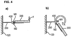
- Figure 4 shows a further embodiment of such a mounting mechanism.
- FIG 4 the housing 120 of a peritoneal dialysis machine is schematically identified by reference numeral 120.
- the holder 250 extends in front of it in the horizontal direction. At the region or end region of the holder 250 facing away from the housing 120 there is a hinge 400 around which the receptacle 300 according to the first position Figure 4 a) according to the second position Figure 4 b) can be pivoted downwards. This is indicated by the arrow Figure 4 b) indicated.
- the fixation of the receptacle 300 in the first position, ie in the horizontal position, is not produced by a snap-in connection, but by the magnets M1 and M2, one magnet M1 on the holder 250 and the other magnet M2 on the receptacle 300 which can be pivoted relative thereto is arranged.
- the magnetic force is sufficient to hold the receptacle 300 in the position shown.
Landscapes
- Health & Medical Sciences (AREA)
- Engineering & Computer Science (AREA)
- Heart & Thoracic Surgery (AREA)
- Animal Behavior & Ethology (AREA)
- Public Health (AREA)
- Anesthesiology (AREA)
- Hematology (AREA)
- Life Sciences & Earth Sciences (AREA)
- Vascular Medicine (AREA)
- General Health & Medical Sciences (AREA)
- Biomedical Technology (AREA)
- Veterinary Medicine (AREA)
- Urology & Nephrology (AREA)
- Emergency Medicine (AREA)
- General Engineering & Computer Science (AREA)
- Mechanical Engineering (AREA)
- External Artificial Organs (AREA)
Description
- Die vorliegende Erfindung betrifft ein Peritonealdialysegerät mit wenigstens einer Aufnahme zur Fixierung eines oder mehrerer Abschnitte eines Schlauchsets zur Leitung von Dialyselösung von und/oder zu dem Patienten.
- Bei aus dem Stand der Technik bekannten Peritonealdialysegeräten ist es bekannt, an dem Gerät eine Aufnahme z.B. für Teile eines Schlauchsets, zur Aufnahme von Konnektoren oder Verschlusskappen oder von Patientenanschlussleitungen etc. vorzusehen. So muss beispielsweise im Rahmen einer Peritonealdialysetherapie der Patient die Patientenanschlussleitung unter aseptischen Bedingungen an eine Aufnahmevorrichtung des Peritonealdialysegerätes anschließen.
- Dazu ist es bekannt, eine Aufnahme, d.h. einen so genannten Organizer, zu verwenden, in dem z.B. der Konnektor einer Patientenanschlussleitung fixiert werden kann, sodass der Patient mit nur einer Hand eine Fluidverbindung herstellen kann.
- Aus dem Stand der Technik sind Peritonealdialysegeräte mit Vorrichtungen zur Aufnahme von Schläuchen bekannt. Beispielsweie offenbart die Druckschrift
US2014/0097303A1 eine Vorrichtung zur Aufnahme und Ausrichtung medizinischer Fluidleitungen. Zudem ist aus der DruckschriftUS2009/0212178A1 eine Standvorrichtung für medizinische Fluidbeutel bekannt. Darüberhinaus offenbart die DruckschriftUS2009/0299273A1 ein tragbares, flexibles Peritonealdialysegerät. - Beim Einlegen des Schlauches bzw. des Konnektors in die Aufnahme des Peritonealdialysegerätes treten Kräfte, insbesondere vertikale Kräfte auf, die von dem mit der Aufnahme verbundenen Teil des Gerätes aufgenommen werden müssen.
- Insbesondere für den Fall, dass die Aufnahme an einem Hebel angeordnet ist, der vergleichsweise lang ausgeführt ist, entsteht dabei ein großes Moment, das zu einer Beschädigung des üblicherweise aus Kunststoff bestehenden Gehäuses des Peritonealdialysegerätes führen kann.
- Der vorliegenden Erfindung liegt daher die Aufgabe zugrunde, ein Peritonealdialysegerät der eingangs genannten Art dahingehend weiterzubilden, dass auch beim Auftreten vergleichsweise großer Kräfte oder Momente auf die Aufnahme eine Beschädigung des Gerätes und insbesondere des Gerätegehäuses vermieden wird.
- Diese Aufgabe wird durch ein Peritonealdialysegerät mit den Merkmalen des Anspruchs 1 gelöst. Danach ist vorgesehen, dass zumindest eine erste Schwenkachse vorgesehen ist, um die die Aufnahme von einer ersten Position in eine zweite Position verschwenkbar ist.
- Dadurch lässt sich der Vorteil erreichen, dass bei Überschreiten einer bestimmten Kraft oder eines bestimmten Momentes die Aufnahme von einer ersten in eine zweite Position verschwenkt wird und somit die auf das Gehäuse wirkenden Kräfte bzw. Momente verringert werden. Die erste Schwenkachse erfüllt somit die Aufgabe einer Überlastsicherung, die eine Beschädigung des Gehäuses oder eines sonstigen Elementes des Peritonealdialysegerätes, an dem die Aufnahme angeordnet ist, verhindert.
- In einer bevorzugten Ausgestaltung der Erfindung weist das Peritonealdialysegerät wenigstens ein Element auf, bei dem es sich vorzugsweise um das Gerätegehäuse handelt, wobei die Aufnahme unmittelbar an diesem Element angeordnet ist und wobei sich die erste Schwenkachse an dem Element bzw. an dem Gehäuse befindet.
- Von der Erfindung ist jedoch auch der Fall umfasst, dass das Peritonealdialysegerät ein Element bzw. ein Gehäuse aufweist, und dass die Aufnahme nicht unmittelbar daran befestigt ist, sondern mittelbar über wenigstens eine Halterung. In diesem Fall kann sich die erste Schwenkachse zwischen der Halterung und der Aufnahme und/oder zwischen der Halterung und dem Element bzw. dem Gerätegehäuse befinden.
- In allen Fällen ist sichergestellt, dass die Aufnahme zu großen Kräften "ausweicht", indem sie um die erste Schwenkachse verschwenkt wird, wenn bestimmte Kräfte oder Momente überschritten werden.
- Vorzugsweise verläuft die erste Schwenkachse horizontal oder im Wesentlichen horizontal. Auch andere Orientierungen der ersten Schwenkachse sind denkbar und von der Erfindung mit umfasst. Wesentlich ist, dass die erste Schwenkachse ein Ausweichen der Aufnahme bei zu großen Kräften bzw. Momenten ermöglicht und somit eine Beschädigung des Elementes des Gerätes verhindert, mit dem die Aufnahme verbunden ist.
- In einer weiteren Ausgestaltung der Erfindung ist die Aufnahme in ihrer ersten, d.h. nicht verschwenkten Position horizontal oder im Wesentlichen horizontal ausgerichtet. Ausgehend von dieser Position kann sie mittels der ersten Schwenkachse z.B. in eine vertikale oder schräg nach unten gerichtete Position verschwenkt werden.
- In einer weiteren Ausgestaltung der Erfindung ist vorgesehen, dass das Peritonealdialysegerät wenigstens ein Element vorzugsweise wenigstens ein Gehäuse aufweist, an dem sich zumindest eine zweite Schwenkachse befindet, die vorzugsweise nicht parallel zur ersten Schwenkachse verläuft und um die die Aufnahme oder eine mit der Aufnahme in Verbindung stehende Halterung verschwenkbar ist. So ist es möglich, die Aufnahme um diese zweite Schwenkachse z.B. von einem Bereich neben dem Gehäuse vor das Gehäuse zu drehen.
- Diese zweite Schwenkachse kann vertikal oder im Wesentlichen vertikal verlaufen. Auch andere Orientierungen der zweiten Schwenkachse sind denkbar und von der Erfindung mit umfasst.
- Vorzugsweise ist die zweite Schwenkachse unterhalb des Gerätegehäuses angeordnet.
- Um sicherzustellen, dass die Aufnahme erst bei Überschreiten einer bestimmten auf diese wirkenden Kraft oder Moment von der ersten in die zweite Position verschwenkt wird, können Halterungsmittel vorhanden sein, die so ausgebildet sind, das sie ein Verschwenken in die zweite Position erst dann ermöglichen, wenn die auf die Aufnahme wirkende Kraft bzw. das auf diese wirkende Moment einen Grenzwert übersteigt. Auf diese Weise wird vermieden, dass in der nicht verschwenkten Position eine unzulässige Kraft z.B. von oben auf die Aufnahme bzw. auf die Halterung wirkt, die auf das Gerätegehäuse übertragen wird.
- Bei den genannten Halterungsmitteln kann es sich um wenigstens zwei Teile handeln, die durch eine kraft- oder formschlüssige Verbindung miteinander in Verbindung stehen oder auch um einen oder mehrere Magneten.
- Beispielsweise kann ein Klappmechanismus in Form von Scharnieren, Magneten oder Rastvorrichtungen vorgesehen sein, sodass der Organizer bzw. die Aufnahme nach unten abklappen kann.
- An dieser Stelle wird darauf hingewiesen, dass der Begriff "Schwenkachse" jeden beliebigen Mechanismus, ein- oder mehrteilig, mit einer oder mehreren Schwenkachsen umfasst, um die die Aufnahme verschwenkt bzw. abgeklappt werden kann. Beispiele sind die Verwendung eines oder mehrerer Bolzen, die in Lagern aufgenommen sind, ein Hebelmechanismus, Vorsprünge, die in Ausnehmungen aufgenommen sind etc. Auch ein Filmscharnier ist denkbar und von der Erfindung mitumfasst.
- Weitere Einzelheiten und Vorteile der Erfindung werden anhand eines in der Zeichnung dargestellten Ausführungsbeispiels näher erläutert.
- Es zeigen:
- Figur 1:
- eine perspektivische Ansicht eines Peritonealdialysegerätes gemäß der Erfindung,
- Figur 2:
- eine Detailansicht des Gehäuses mit Halterung und Aufnahme,
- Figur 3:
- eine weitere Detailansicht des Gehäuses mit Halterung und Aufnahme,
- Figur 4:
- eine schematische Ansicht der erfindungsgemäßen Anordnung in der ersten Position und in der zweiten Position der Aufnahme.
-
Figur 1 zeigt ein Peritonealdialysegerät gemäß der Erfindung in einer perspektivischen Ansicht. - Das Gerät weist einen Gerätefuß 100 auf, sowie einen sich von diesen nach oben erstreckenden Gehäuseträger 110. Das Bezugszeichen 120 kennzeichnet das Gerätegehäuse, das an dem Gehäuseträger 110 angeordnet ist. In dem Gerätegehäuse 120 befindet sich die für den Betrieb des Gehäuses notwendige Steuerung und ggf. Anzeige und/oder Bedienelemente.
- Oberhalb des Gerätegehäuses 120 befindet sich eine Wägeschale, in die Lösungsbeutel mit zu dem verabreichendem Dialysat eingelegt werden können.
- Unterhalb des Gerätegehäuses 120 und unmittelbar oberhalb des Fußes 100 befindet sich die Aufnahmeschale, in der Beutel angeordnet sind, die mit verbrauchtem Dialysat befüllt werden.
- Das Bezugszeichen 200 kennzeichnet eine Anordnung, die die erfindungsgemäße Aufnahme umfasst, die im Folgenden näher beschrieben wird.
-
Figur 2 zeigt einen Teilbereich des Gerätegehäuses 120. - Wie dies aus
Figur 2 ersichtlich ist, befindet sich in einem Eckbereich auf der Unterseite des Gerätegehäuses ein Vorsprung 130, dessen unterer Teil 131 relativ zu dem Gehäuse 120 um die vertikale Schwenkachse S2 verdrehbar ist. - An diesem Element 131 befindet sich die Halterung 250. Die Halterung 250 erstreckt sich in der in
Figur 2 dargestellten Position in horizontaler Richtung von dem Element 131 weg. - Sie ist relativ zu dem Element 131 um eine horizontal verlaufende erste Schwenkachse S1 verschwenkbar.
- Mit dieser Halterung 250 ist beispielsweise durch Kraft- oder Formschluss die Aufnahme 300 verbindbar, die im Folgenden auch als Organizer bezeichnet wird. Dieser Organizer dient zur Aufnahme von einem oder mehreren Bestandteilen eines Schlauchsets eines Peritonealdialysegerätes. Dazu gehören beispielsweise die Schläuche selbst, sowie auch Konnektoren zum Verbinden zweier Schlauchabschnitte.
- So ist es beispielsweise denkbar, dass diese Aufnahme dazu verwendet wird, den Schlauch, der mit dem Dialysebeutel verbunden ist mit dem Patientenschlauch zu verbinden, der in die Bauchhöhle führt. Dazu können an beiden Enden Konnektoren vorgesehen sein, die vorzugsweise formschlüssig in der Aufnahme 300 angeordnet sind, sodass der Patient nur eine Hand braucht, um eine entsprechende Fluidverbindung herzustellen.
- Grundsätzlich ist die Aufnahme nicht genau auf diese Verwendung beschränkt, sondern kann jedes beliebige geeignete Element eines Schlauchsets eines Peritonealdialysegerätes aufnehmen.
- An dieser Stelle wird darauf hingewiesen, dass die vorliegende Erfindung das Peritonealdialysegerät als solches, d.h. ohne Schlauchset, sowie auch ein Peritonealdialysegerät unter Schutz stellt, in dem sich ein solches Schlauchset befindet.
- Wie dies oben ausgeführt wurde, ist die Halterung 250 unterhalb des Gerätegehäuses 120 schwenkbar angeordnet. So kann sie beispielsweise von einer Position, in der sie in eine Richtung neben das Gehäuse 120 weist, nach vorne verdreht werden. Zum Bestücken mit dem Disposable und auch während der Behandlung kann der Organizer bzw. die Aufnahme 300 z.B. vor das Gerät, d.h. gemäß
Figur 2 nach vorne verdreht werden. - Wird nun die Aufnahme 300 mit Elementen des Schlauchsets, wie beispielsweise mit einem Konnektor bestückt, wirken auf die Aufnahme 300 Kräfte, im Allgemeinen von oben.
- Diese Kräfte werden dann über die Halterung 250 auf das Element 131 und von diesem auf das Gehäuse 120 übertragen. Dabei kann es zu unzulässigen Krafteinleitungen in das üblicherweise aus Kunststoff bestehende Gehäuse 120 kommen, das dann ggf. beschädigt wird.
- Um eine solche Beschädigung zu vermeiden, ist vorgesehen, dass die Aufnahme bzw. die Halterung 250 schwenkbar an dem Gehäuse 120 angeordnet ist. Drückt eine unzulässig große Kraft von oben auf die Aufnahme 300, wird die Halterung 250 mit der Aufnahme 300 nach unten verschwenkt und weicht somit aus. Der Organizer klappt somit nach unten ab.
- Statt einer einfachen Schwenkachse kann auch ein beliebiger anderer Klappmechanismus, Hebelmechanismus oder sonstiger Mechanismus verwendet werden, um ein solches Abklappern bzw. Verschwenken der Aufnahme 300 zu ermöglichen.
-
Figur 3 zeigt eine Detaildarstellung des Elementes 131, das um die zweite Schwenkachse S2 relativ zum Gehäuse verdrehbar ist. An diesem Element 131 befindet sich um die erste Schwenkachse S1 verschwenkbar die Halterung 250, wie dies inFigur 2 ausgeführt wurde. - Um ein ungewolltes Herabschwenken der Halterung 250 und somit auch des Organizers 300 zu verhindern, ist ein Haltemechanismus vorgesehen, der beispielsweise in Form einer Rastvorrichtung ausgeführt sein kann. Das Bezugszeichen 260 in
Figur 3 kennzeichnet einen federbelasteten Kolben, Kugel oder sonstigen Vorsprung, der in der ersten Position der Aufnahme in eine entsprechende Aufnahme 262 eingedrückt wird. Übersteigt die auf die Aufnahme wirkenden Kraft einen bestimmten Grenzwert, wird der Kolben 260 etc. entgegen der Federkraft eingedrückt, woraufhin die Halterung 250 nach unten verschwenkt werden kann. -
Figur 4 zeigt ein weiteres Ausführungsbeispiel eines solchen Halterungsmechanismus. - In
Figur 4 ist mit den Bezugszeichen 120 schematisch das Gehäuse eines Peritonealdialysegerätes gekennzeichnet. - Vor diesem erstreckt sich in horizontaler Richtung die Halterung 250. Am von dem Gehäuse 120 abgewandten Bereich bzw. Endbereich der Halterung 250 befindet sich ein Scharnier 400, um das die Aufnahme 300 von der ersten Position gemäß
Figur 4 a) in die zweite Position gemäßFigur 4 b) nach unten verschwenkt werden kann. Dies ist durch den Pfeil gemäßFigur 4 b) angedeutet. - In dem Ausführungsbeispiel gemäß
Figur 4 wird die Fixierung der Aufnahme 300 in der ersten Position, d.h. in der horizontalen Position nicht durch eine Rastverbindung hergestellt, sondern durch die Magnete M1 und M2, wobei ein Magnet M1 an der Halterung 250 und der andere Magnet M2 an der relativ dazu verschwenkbaren Aufnahme 300 angeordnet ist. - In der ersten Position der Aufnahme gemäß
Figur 4 a) ist die Magnetkraft ausreichend, um die Aufnahme 300 in der dargestellten Position zu halten. - Wird die Kraft F zu groß, übersteigt diese die Magnetkraft, woraufhin die Aufnahme 300 nach unten verschwenkt wird.
- Unabhängig von dem genauen Mechanismus des Verschwenkens bzw. Abklappens der Aufnahme 300 durch eine Schwenkachse, Scharniere etc. wird sichergestellt, dass zu große auf die Aufnahme 300 wirkenden Kräfte bzw. Momente nicht oder nur abgemindert auf das Gehäuse 120 übertragen werden. Somit wird die Wahrscheinlichkeit für das Auftreten von Beschädigungen am Gerät und insbesondere an dem Gerätegehäuse verringert.
Claims (6)
- Peritonealdialysegerät mit wenigstens einer Aufnahme (300) zur Fixierung eines oder mehrerer Abschnitte eines Schlauchsets zur Leitung von Dialyselösung von und/oder zu dem Patienten,
wobei wenigstens ein erste Schwenkachse (S1) vorgesehen ist, um die die Aufnahme (300) von einer ersten Position in eine zweite Position abklappbar ist,
wobei das Peritonealdialysegerät wenigstens ein Element (131) aufweist und die Aufnahme (300)
mittels einer Halterung (250) unmittelbar an dem Element (131) angeordnet ist, wobei sich die erste Schwenkachse (S1) an dem Element befindet und die Halterung (250) um die erste Schwenkachse (S1) abklappbar ist,
wobei das Peritonealdialysegerät wenigstens ein Gehäuse aufweist, an dem eine zweite Schwenkachse (S2) angeordnet ist, die nicht parallel zu der ersten Schwenkachse (S1) verläuft und um die das Element (131) mit der daran angeordneten Aufnahme (300) und die mit der daran angeordneten Aufnahme (300) in Verbindung stehende Halterung (250) relativ zum Gehäuse verdrehbar ist,
dadurch gekennzeichnet, dass
ein Haltemechanismus in Form einer Rastvorrichtung vorhanden ist und die Rastvorrichtung in Form eines federbelasteten Vorsprungs (260) und einer zugehörigen Aufnahme (262) für den federbelasteten Vorsprungs (260) derart ausgebildet ist, dass diese ein Abklappen der Halterung (250) von der ersten in die zweite Position nur bei Überschreiten eines Grenzwerts einer auf die Halterung bzw. auf die Aufnahme (300) wirkenden Kraft ermöglichen, wodurch der Vorsprung (260) entgegen der Federkraft eingedrückt wird und die Halterung (300) abgeklappt wird. - Peritonealdialysegerät nach Anspruch 1, dadurch gekennzeichnet, dass sich die erste Schwenkachse (S1) zwischen der Halterung (250) und dem Element (131) befindet.
- Peritonealdialysegerät nach einem der vorhergehenden Ansprüche, dadurch gekennzeichnet, dass die erste (S1) Schwenkachse horizontal oder im Wesentlichen Horizontal angeordnet ist.
- Peritonealdialysegerät nach einem der vorhergehenden Ansprüche, dadurch gekennzeichnet, dass die Aufnahme (300) in ihrer ersten Position horizontal oder im Wesentlichen Horizontal ausgerichtet ist.
- Peritonealdialysegerät nach einem der vorhergehenden Ansprüche, dadurch gekennzeichnet, dass die zweite Schwenkachse (S2) vertikal oder im Wesentlichen vertikal verläuft.
- Peritonealdialysegerät nach einem der vorhergehenden Ansprüche, dadurch gekennzeichnet, dass die erste und/oder die zweite Schwenkachse (S1, S2) unterhalb des Gehäuses (120) angeordnet ist.
Applications Claiming Priority (2)
| Application Number | Priority Date | Filing Date | Title |
|---|---|---|---|
| DE102015010431.4A DE102015010431A1 (de) | 2015-08-11 | 2015-08-11 | Peritonealdialysegerät |
| PCT/EP2016/001364 WO2017025186A1 (de) | 2015-08-11 | 2016-08-09 | Peritonealdialysegerät |
Publications (2)
| Publication Number | Publication Date |
|---|---|
| EP3334475A1 EP3334475A1 (de) | 2018-06-20 |
| EP3334475B1 true EP3334475B1 (de) | 2020-03-04 |
Family
ID=56740998
Family Applications (1)
| Application Number | Title | Priority Date | Filing Date |
|---|---|---|---|
| EP16754189.5A Active EP3334475B1 (de) | 2015-08-11 | 2016-08-09 | Peritonealdialysegerät |
Country Status (11)
| Country | Link |
|---|---|
| US (1) | US11224682B2 (de) |
| EP (1) | EP3334475B1 (de) |
| CN (1) | CN107921193B (de) |
| AR (1) | AR105661A1 (de) |
| BR (1) | BR112018002704B1 (de) |
| DE (1) | DE102015010431A1 (de) |
| ES (1) | ES2796489T3 (de) |
| MX (1) | MX2018001752A (de) |
| MY (1) | MY191673A (de) |
| TW (1) | TWI725984B (de) |
| WO (1) | WO2017025186A1 (de) |
Families Citing this family (4)
| Publication number | Priority date | Publication date | Assignee | Title |
|---|---|---|---|---|
| DE102017110573A1 (de) * | 2017-05-16 | 2018-11-22 | Fresenius Medical Care Deutschland Gmbh | Peritonealdialysesystem |
| US10814057B2 (en) | 2018-04-05 | 2020-10-27 | Baxter International Inc. | Disposable set for a gravity fed dialysis system |
| DE102018113322A1 (de) * | 2018-06-05 | 2019-12-05 | Fresenius Medical Care Deutschland Gmbh | Organizer für die Peritonealdialyse und medizinisches System |
| WO2020210447A1 (en) | 2019-04-09 | 2020-10-15 | Nxstage Medical, Inc. | Line holder |
Family Cites Families (32)
| Publication number | Priority date | Publication date | Assignee | Title |
|---|---|---|---|---|
| US1800349A (en) * | 1924-09-19 | 1931-04-14 | Hurason Harry | Locking joint |
| US4507042A (en) * | 1981-10-07 | 1985-03-26 | Yaskawa Electric Mfg. Co., Ltd. | Cable support of a robot |
| DE3434899A1 (de) * | 1983-10-19 | 1985-05-23 | Kuka Schweissanlagen + Roboter Gmbh, 8900 Augsburg | Vorrichtung zum aussenseitigen halten und fuehren von versorgungsleitungen zu bewegten werkzeugen von manipulatoren |
| US4767257A (en) * | 1985-12-23 | 1988-08-30 | Mitsubishi Denki Kabushiki Kaisha | Industrial robot |
| US4770377A (en) * | 1986-08-08 | 1988-09-13 | Callaway James J | Cord holding device |
| US4820274A (en) * | 1987-08-27 | 1989-04-11 | Pradip V. Choksi | Medical tube and/or cable holder |
| US5240092A (en) * | 1992-03-19 | 1993-08-31 | W. L. Gore & Associates, Inc. | Moving strain relief for spiralled flexible cable |
| FR2691051B1 (fr) * | 1992-05-14 | 1996-10-18 | Nicolas Simone | Dispositif de fixation d'une paire de lunettes a un couvre-chef. |
| US5279486A (en) * | 1993-03-31 | 1994-01-18 | Harmon Elbert C | Medical support device |
| US5502859A (en) * | 1993-12-23 | 1996-04-02 | Kim; Wha J. | Multi-directional brush |
| US5581838A (en) * | 1995-04-07 | 1996-12-10 | Rocco; Anthony C. | Articulating toothbrush assembly |
| US6431018B1 (en) * | 1999-09-09 | 2002-08-13 | Fanuc Ltd. | Guide device for wiring member and/or piping member and robot with guide device |
| US6887214B1 (en) * | 2000-09-12 | 2005-05-03 | Chf Solutions, Inc. | Blood pump having a disposable blood passage cartridge with integrated pressure sensors |
| KR200291221Y1 (ko) * | 2002-07-02 | 2002-10-11 | 박승배 | 착탈기능의 클립장치가 내장된 선글라스홀더 |
| US7837167B2 (en) * | 2003-09-25 | 2010-11-23 | Baxter International Inc. | Container support device |
| US7905855B2 (en) * | 2007-07-05 | 2011-03-15 | Baxter International Inc. | Dialysis system having non-invasive temperature sensing |
| US7618029B2 (en) * | 2008-01-10 | 2009-11-17 | Lisle Corporation | Wire clamping device |
| US8545425B2 (en) * | 2008-01-18 | 2013-10-01 | Baxter International | Reusable effluent drain container for dialysis and other medical fluid therapies |
| US8152116B2 (en) * | 2008-02-27 | 2012-04-10 | Baxter International Inc. | Dialysate bag seal breakage sensor incorporated in dialysate bag management |
| US8262602B2 (en) | 2008-06-02 | 2012-09-11 | Baxter International Inc. | Remote exchange peritoneal dialysis |
| US8103155B2 (en) * | 2008-07-17 | 2012-01-24 | Jrd International Enterprises, Llc | Manually adjustable hair dryer mount for use with a hand-held hair dryer |
| NZ592652A (en) * | 2008-10-30 | 2013-10-25 | Fresenius Med Care Hldg Inc | Modular, portable dialysis system |
| WO2012006425A2 (en) * | 2010-07-07 | 2012-01-12 | Deka Products Limited Partnership | Medical treatment system and methods using a plurality of fluid lines |
| DE102011085793A1 (de) * | 2011-11-04 | 2013-05-08 | Airbus Operations Gmbh | Halterungsvorrichtung zum Haltern eines Kabels oder einer Leitung an einer Strukturkomponente eines Luft- oder Raumfahrzeugs sowie Luft- oder Raumfahrzeug |
| US20130312644A1 (en) * | 2012-05-25 | 2013-11-28 | Heman Miller, Inc. | Keyboard tray and attached mouse platform having multiple degrees of movement |
| DE102012105912A1 (de) | 2012-07-03 | 2014-01-09 | B. Braun Avitum Ag | Haltevorrichtung und medizinisches Gerät zur extrakorporalen Blutbehandlung mit Haltevorrichtung |
| DE102012013465A1 (de) | 2012-07-09 | 2014-05-08 | Eppendorf Ag | Haltevorrichtung |
| US20140097303A1 (en) | 2012-10-09 | 2014-04-10 | Fresenius Medical Care Holdings, Inc. | Medical Fluid Line Alignment Devices and Related Systems and Methods |
| US20140259837A1 (en) * | 2013-03-14 | 2014-09-18 | Carefusion 303, Inc. | Iv system to assist with line management |
| WO2014151508A1 (en) * | 2013-03-15 | 2014-09-25 | Fresenius Medical Care Holdings, Inc. | Improved dialyzer holder and improved airless bloodline priming method |
| US9511185B2 (en) * | 2014-04-18 | 2016-12-06 | Regents Of The University Of Minnesota | Intravenous line lifter devices, systems and methods |
| DE102015010468A1 (de) * | 2015-08-11 | 2017-02-16 | Fresenius Medical Care Deutschland Gmbh | Peritonealdialysegerät |
-
2015
- 2015-08-11 DE DE102015010431.4A patent/DE102015010431A1/de not_active Withdrawn
-
2016
- 2016-08-09 MY MYPI2018700488A patent/MY191673A/en unknown
- 2016-08-09 CN CN201680047220.7A patent/CN107921193B/zh active Active
- 2016-08-09 MX MX2018001752A patent/MX2018001752A/es unknown
- 2016-08-09 EP EP16754189.5A patent/EP3334475B1/de active Active
- 2016-08-09 BR BR112018002704-9A patent/BR112018002704B1/pt active IP Right Grant
- 2016-08-09 WO PCT/EP2016/001364 patent/WO2017025186A1/de not_active Ceased
- 2016-08-09 US US15/752,141 patent/US11224682B2/en active Active
- 2016-08-09 ES ES16754189T patent/ES2796489T3/es active Active
- 2016-08-10 TW TW105125411A patent/TWI725984B/zh active
- 2016-08-10 AR ARP160102449A patent/AR105661A1/es active IP Right Grant
Non-Patent Citations (1)
| Title |
|---|
| None * |
Also Published As
| Publication number | Publication date |
|---|---|
| CN107921193A (zh) | 2018-04-17 |
| TW201718036A (zh) | 2017-06-01 |
| BR112018002704B1 (pt) | 2023-11-07 |
| TWI725984B (zh) | 2021-05-01 |
| MX2018001752A (es) | 2019-01-31 |
| EP3334475A1 (de) | 2018-06-20 |
| ES2796489T3 (es) | 2020-11-27 |
| MY191673A (en) | 2022-07-06 |
| AR105661A1 (es) | 2017-10-25 |
| BR112018002704A2 (de) | 2018-10-02 |
| DE102015010431A1 (de) | 2017-02-16 |
| CN107921193B (zh) | 2021-04-16 |
| WO2017025186A1 (de) | 2017-02-16 |
| US20180236155A1 (en) | 2018-08-23 |
| US11224682B2 (en) | 2022-01-18 |
Similar Documents
| Publication | Publication Date | Title |
|---|---|---|
| EP2542204B1 (de) | Flaschenhalter für eine injektionsvorrichtung | |
| EP2682603B1 (de) | Schlauchrollenpumpe mit schwenkbarem Deckel und medizinisches Gerät zur extrakorporalen Blutbehandlung mit Schlauchrollenpumpe | |
| WO2001074259A1 (de) | Medizinische einrichtung mit einer antriebseinrichtung für eine nadel | |
| EP2735322B1 (de) | Kartuschenhalterung einer Dialysemaschine mit integrierter Positionierhilfe | |
| DE102016008655B4 (de) | Anlage für biotechnologische Anwendungen mit Träger zur Lagerung von Komponenten | |
| EP3334475A1 (de) | Peritonealdialysegerät | |
| EP2421586A1 (de) | Haltevorrichtung zum halten einer externen funktionseinrichtung an einer behandlungsvorrichtung, externe funktionseinrichtung sowie behandlungsvorrichtung | |
| WO2014135582A1 (de) | Fahrbare strahlenschutzanordnung | |
| EP2682606A1 (de) | Multikonnektor und medizinisches Gerät zur extrakorporalen Blutbehandlung | |
| EP1616588A1 (de) | Anordnung zum Kuppeln eines Intravenös-Schlauches mit einer Infusionspumpe | |
| EP4021556A1 (de) | Medizinischer konnektor mit automatischer abdichtung bei der dekonnektion | |
| EP2482866B1 (de) | Gehäuse mit veschlussklappe | |
| EP2682139A1 (de) | Haltevorrichtung und medizinisches Gerät zur extrakorporalen Blutbehandlung mit Haltevorrichtung | |
| DE102005048211B4 (de) | Chirurgische Lagerung, chirurgisches System und Verfahren zum Reinigen | |
| DE202011052477U1 (de) | Heißdrahtschneidgerät | |
| EP3600494B1 (de) | Haltevorrichtung für medizinische behandlungsvorrichtungen | |
| EP3541444A1 (de) | Halterung zur befestigung an einem medizinischen gerät | |
| DE2925414C2 (de) | Körperstativ für photographisches oder optisches Gerät | |
| EP4314573B1 (de) | Kopplungsvorrichtung | |
| WO2012104043A1 (de) | Einrichtung zum führen eines kabels in einer medizintechnischen dosiervorrichtung, dosiervorrichtung, behandlungsvorrichtung sowie verfahren | |
| WO2020188040A1 (de) | Extrakorporale blutbehandlungsmaschine mit poka yoke für druckaufnehmer | |
| DE20213004U1 (de) | Vorrichtung zur Halterung von Schlauchleitungen | |
| DE102024131867A1 (de) | Infusionsüberwachungsvorrichtung und medizinisches Infusionssystem | |
| WO2026093481A1 (de) | Infusionsüberwachungsvorrichtung und medizinisches infusionssystem | |
| DE10256772B4 (de) | Vorrichtung zur Regulierung der Strömung in Schlauchleitungen, insbesondere für enterale Überleitsysteme und enterales Überleitsystem mit einer derartigen Vorrichtung |
Legal Events
| Date | Code | Title | Description |
|---|---|---|---|
| STAA | Information on the status of an ep patent application or granted ep patent |
Free format text: STATUS: THE INTERNATIONAL PUBLICATION HAS BEEN MADE |
|
| PUAI | Public reference made under article 153(3) epc to a published international application that has entered the european phase |
Free format text: ORIGINAL CODE: 0009012 |
|
| STAA | Information on the status of an ep patent application or granted ep patent |
Free format text: STATUS: REQUEST FOR EXAMINATION WAS MADE |
|
| 17P | Request for examination filed |
Effective date: 20180308 |
|
| AK | Designated contracting states |
Kind code of ref document: A1 Designated state(s): AL AT BE BG CH CY CZ DE DK EE ES FI FR GB GR HR HU IE IS IT LI LT LU LV MC MK MT NL NO PL PT RO RS SE SI SK SM TR |
|
| AX | Request for extension of the european patent |
Extension state: BA ME |
|
| DAV | Request for validation of the european patent (deleted) | ||
| DAX | Request for extension of the european patent (deleted) | ||
| STAA | Information on the status of an ep patent application or granted ep patent |
Free format text: STATUS: EXAMINATION IS IN PROGRESS |
|
| 17Q | First examination report despatched |
Effective date: 20190201 |
|
| GRAP | Despatch of communication of intention to grant a patent |
Free format text: ORIGINAL CODE: EPIDOSNIGR1 |
|
| STAA | Information on the status of an ep patent application or granted ep patent |
Free format text: STATUS: GRANT OF PATENT IS INTENDED |
|
| INTG | Intention to grant announced |
Effective date: 20191118 |
|
| GRAS | Grant fee paid |
Free format text: ORIGINAL CODE: EPIDOSNIGR3 |
|
| GRAA | (expected) grant |
Free format text: ORIGINAL CODE: 0009210 |
|
| STAA | Information on the status of an ep patent application or granted ep patent |
Free format text: STATUS: THE PATENT HAS BEEN GRANTED |
|
| AK | Designated contracting states |
Kind code of ref document: B1 Designated state(s): AL AT BE BG CH CY CZ DE DK EE ES FI FR GB GR HR HU IE IS IT LI LT LU LV MC MK MT NL NO PL PT RO RS SE SI SK SM TR |
|
| REG | Reference to a national code |
Ref country code: GB Ref legal event code: FG4D Free format text: NOT ENGLISH |
|
| REG | Reference to a national code |
Ref country code: CH Ref legal event code: EP |
|
| REG | Reference to a national code |
Ref country code: AT Ref legal event code: REF Ref document number: 1239643 Country of ref document: AT Kind code of ref document: T Effective date: 20200315 |
|
| REG | Reference to a national code |
Ref country code: DE Ref legal event code: R096 Ref document number: 502016009048 Country of ref document: DE |
|
| REG | Reference to a national code |
Ref country code: IE Ref legal event code: FG4D Free format text: LANGUAGE OF EP DOCUMENT: GERMAN |
|
| PG25 | Lapsed in a contracting state [announced via postgrant information from national office to epo] |
Ref country code: FI Free format text: LAPSE BECAUSE OF FAILURE TO SUBMIT A TRANSLATION OF THE DESCRIPTION OR TO PAY THE FEE WITHIN THE PRESCRIBED TIME-LIMIT Effective date: 20200304 Ref country code: NO Free format text: LAPSE BECAUSE OF FAILURE TO SUBMIT A TRANSLATION OF THE DESCRIPTION OR TO PAY THE FEE WITHIN THE PRESCRIBED TIME-LIMIT Effective date: 20200604 Ref country code: RS Free format text: LAPSE BECAUSE OF FAILURE TO SUBMIT A TRANSLATION OF THE DESCRIPTION OR TO PAY THE FEE WITHIN THE PRESCRIBED TIME-LIMIT Effective date: 20200304 |
|
| REG | Reference to a national code |
Ref country code: NL Ref legal event code: MP Effective date: 20200304 |
|
| PG25 | Lapsed in a contracting state [announced via postgrant information from national office to epo] |
Ref country code: HR Free format text: LAPSE BECAUSE OF FAILURE TO SUBMIT A TRANSLATION OF THE DESCRIPTION OR TO PAY THE FEE WITHIN THE PRESCRIBED TIME-LIMIT Effective date: 20200304 Ref country code: GR Free format text: LAPSE BECAUSE OF FAILURE TO SUBMIT A TRANSLATION OF THE DESCRIPTION OR TO PAY THE FEE WITHIN THE PRESCRIBED TIME-LIMIT Effective date: 20200605 Ref country code: SE Free format text: LAPSE BECAUSE OF FAILURE TO SUBMIT A TRANSLATION OF THE DESCRIPTION OR TO PAY THE FEE WITHIN THE PRESCRIBED TIME-LIMIT Effective date: 20200304 Ref country code: LV Free format text: LAPSE BECAUSE OF FAILURE TO SUBMIT A TRANSLATION OF THE DESCRIPTION OR TO PAY THE FEE WITHIN THE PRESCRIBED TIME-LIMIT Effective date: 20200304 Ref country code: BG Free format text: LAPSE BECAUSE OF FAILURE TO SUBMIT A TRANSLATION OF THE DESCRIPTION OR TO PAY THE FEE WITHIN THE PRESCRIBED TIME-LIMIT Effective date: 20200604 |
|
| REG | Reference to a national code |
Ref country code: LT Ref legal event code: MG4D |
|
| PG25 | Lapsed in a contracting state [announced via postgrant information from national office to epo] |
Ref country code: NL Free format text: LAPSE BECAUSE OF FAILURE TO SUBMIT A TRANSLATION OF THE DESCRIPTION OR TO PAY THE FEE WITHIN THE PRESCRIBED TIME-LIMIT Effective date: 20200304 |
|
| PG25 | Lapsed in a contracting state [announced via postgrant information from national office to epo] |
Ref country code: PT Free format text: LAPSE BECAUSE OF FAILURE TO SUBMIT A TRANSLATION OF THE DESCRIPTION OR TO PAY THE FEE WITHIN THE PRESCRIBED TIME-LIMIT Effective date: 20200729 Ref country code: RO Free format text: LAPSE BECAUSE OF FAILURE TO SUBMIT A TRANSLATION OF THE DESCRIPTION OR TO PAY THE FEE WITHIN THE PRESCRIBED TIME-LIMIT Effective date: 20200304 Ref country code: CZ Free format text: LAPSE BECAUSE OF FAILURE TO SUBMIT A TRANSLATION OF THE DESCRIPTION OR TO PAY THE FEE WITHIN THE PRESCRIBED TIME-LIMIT Effective date: 20200304 Ref country code: SM Free format text: LAPSE BECAUSE OF FAILURE TO SUBMIT A TRANSLATION OF THE DESCRIPTION OR TO PAY THE FEE WITHIN THE PRESCRIBED TIME-LIMIT Effective date: 20200304 Ref country code: LT Free format text: LAPSE BECAUSE OF FAILURE TO SUBMIT A TRANSLATION OF THE DESCRIPTION OR TO PAY THE FEE WITHIN THE PRESCRIBED TIME-LIMIT Effective date: 20200304 Ref country code: EE Free format text: LAPSE BECAUSE OF FAILURE TO SUBMIT A TRANSLATION OF THE DESCRIPTION OR TO PAY THE FEE WITHIN THE PRESCRIBED TIME-LIMIT Effective date: 20200304 Ref country code: IS Free format text: LAPSE BECAUSE OF FAILURE TO SUBMIT A TRANSLATION OF THE DESCRIPTION OR TO PAY THE FEE WITHIN THE PRESCRIBED TIME-LIMIT Effective date: 20200704 Ref country code: SK Free format text: LAPSE BECAUSE OF FAILURE TO SUBMIT A TRANSLATION OF THE DESCRIPTION OR TO PAY THE FEE WITHIN THE PRESCRIBED TIME-LIMIT Effective date: 20200304 |
|
| REG | Reference to a national code |
Ref country code: ES Ref legal event code: FG2A Ref document number: 2796489 Country of ref document: ES Kind code of ref document: T3 Effective date: 20201127 |
|
| REG | Reference to a national code |
Ref country code: DE Ref legal event code: R097 Ref document number: 502016009048 Country of ref document: DE |
|
| PLBE | No opposition filed within time limit |
Free format text: ORIGINAL CODE: 0009261 |
|
| STAA | Information on the status of an ep patent application or granted ep patent |
Free format text: STATUS: NO OPPOSITION FILED WITHIN TIME LIMIT |
|
| PG25 | Lapsed in a contracting state [announced via postgrant information from national office to epo] |
Ref country code: DK Free format text: LAPSE BECAUSE OF FAILURE TO SUBMIT A TRANSLATION OF THE DESCRIPTION OR TO PAY THE FEE WITHIN THE PRESCRIBED TIME-LIMIT Effective date: 20200304 |
|
| 26N | No opposition filed |
Effective date: 20201207 |
|
| PG25 | Lapsed in a contracting state [announced via postgrant information from national office to epo] |
Ref country code: PL Free format text: LAPSE BECAUSE OF FAILURE TO SUBMIT A TRANSLATION OF THE DESCRIPTION OR TO PAY THE FEE WITHIN THE PRESCRIBED TIME-LIMIT Effective date: 20200304 Ref country code: SI Free format text: LAPSE BECAUSE OF FAILURE TO SUBMIT A TRANSLATION OF THE DESCRIPTION OR TO PAY THE FEE WITHIN THE PRESCRIBED TIME-LIMIT Effective date: 20200304 |
|
| PG25 | Lapsed in a contracting state [announced via postgrant information from national office to epo] |
Ref country code: MC Free format text: LAPSE BECAUSE OF FAILURE TO SUBMIT A TRANSLATION OF THE DESCRIPTION OR TO PAY THE FEE WITHIN THE PRESCRIBED TIME-LIMIT Effective date: 20200304 |
|
| REG | Reference to a national code |
Ref country code: CH Ref legal event code: PL |
|
| PG25 | Lapsed in a contracting state [announced via postgrant information from national office to epo] |
Ref country code: LU Free format text: LAPSE BECAUSE OF NON-PAYMENT OF DUE FEES Effective date: 20200809 Ref country code: LI Free format text: LAPSE BECAUSE OF NON-PAYMENT OF DUE FEES Effective date: 20200831 Ref country code: CH Free format text: LAPSE BECAUSE OF NON-PAYMENT OF DUE FEES Effective date: 20200831 |
|
| REG | Reference to a national code |
Ref country code: BE Ref legal event code: MM Effective date: 20200831 |
|
| PG25 | Lapsed in a contracting state [announced via postgrant information from national office to epo] |
Ref country code: IE Free format text: LAPSE BECAUSE OF NON-PAYMENT OF DUE FEES Effective date: 20200809 Ref country code: BE Free format text: LAPSE BECAUSE OF NON-PAYMENT OF DUE FEES Effective date: 20200831 |
|
| PG25 | Lapsed in a contracting state [announced via postgrant information from national office to epo] |
Ref country code: MT Free format text: LAPSE BECAUSE OF FAILURE TO SUBMIT A TRANSLATION OF THE DESCRIPTION OR TO PAY THE FEE WITHIN THE PRESCRIBED TIME-LIMIT Effective date: 20200304 Ref country code: CY Free format text: LAPSE BECAUSE OF FAILURE TO SUBMIT A TRANSLATION OF THE DESCRIPTION OR TO PAY THE FEE WITHIN THE PRESCRIBED TIME-LIMIT Effective date: 20200304 |
|
| PG25 | Lapsed in a contracting state [announced via postgrant information from national office to epo] |
Ref country code: MK Free format text: LAPSE BECAUSE OF FAILURE TO SUBMIT A TRANSLATION OF THE DESCRIPTION OR TO PAY THE FEE WITHIN THE PRESCRIBED TIME-LIMIT Effective date: 20200304 Ref country code: AL Free format text: LAPSE BECAUSE OF FAILURE TO SUBMIT A TRANSLATION OF THE DESCRIPTION OR TO PAY THE FEE WITHIN THE PRESCRIBED TIME-LIMIT Effective date: 20200304 |
|
| REG | Reference to a national code |
Ref country code: AT Ref legal event code: MM01 Ref document number: 1239643 Country of ref document: AT Kind code of ref document: T Effective date: 20210809 |
|
| PG25 | Lapsed in a contracting state [announced via postgrant information from national office to epo] |
Ref country code: AT Free format text: LAPSE BECAUSE OF NON-PAYMENT OF DUE FEES Effective date: 20210809 |
|
| P01 | Opt-out of the competence of the unified patent court (upc) registered |
Effective date: 20230602 |
|
| PGFP | Annual fee paid to national office [announced via postgrant information from national office to epo] |
Ref country code: ES Payment date: 20250901 Year of fee payment: 10 |
|
| PGFP | Annual fee paid to national office [announced via postgrant information from national office to epo] |
Ref country code: DE Payment date: 20250724 Year of fee payment: 10 |
|
| PGFP | Annual fee paid to national office [announced via postgrant information from national office to epo] |
Ref country code: IT Payment date: 20250723 Year of fee payment: 10 Ref country code: TR Payment date: 20250731 Year of fee payment: 10 |
|
| PGFP | Annual fee paid to national office [announced via postgrant information from national office to epo] |
Ref country code: GB Payment date: 20250725 Year of fee payment: 10 |
|
| PGFP | Annual fee paid to national office [announced via postgrant information from national office to epo] |
Ref country code: FR Payment date: 20250723 Year of fee payment: 10 |