EP3334236B1 - Steuerungsverfahren und lokale vorrichtung auf steuerebene - Google Patents
Steuerungsverfahren und lokale vorrichtung auf steuerebene Download PDFInfo
- Publication number
- EP3334236B1 EP3334236B1 EP15904346.2A EP15904346A EP3334236B1 EP 3334236 B1 EP3334236 B1 EP 3334236B1 EP 15904346 A EP15904346 A EP 15904346A EP 3334236 B1 EP3334236 B1 EP 3334236B1
- Authority
- EP
- European Patent Office
- Prior art keywords
- user equipment
- control plane
- plane device
- remote control
- local control
- Prior art date
- Legal status (The legal status is an assumption and is not a legal conclusion. Google has not performed a legal analysis and makes no representation as to the accuracy of the status listed.)
- Active
Links
Images


Classifications
-
- H—ELECTRICITY
- H04—ELECTRIC COMMUNICATION TECHNIQUE
- H04W—WIRELESS COMMUNICATION NETWORKS
- H04W76/00—Connection management
- H04W76/10—Connection setup
- H04W76/12—Setup of transport tunnels
-
- H—ELECTRICITY
- H04—ELECTRIC COMMUNICATION TECHNIQUE
- H04W—WIRELESS COMMUNICATION NETWORKS
- H04W28/00—Network traffic management; Network resource management
- H04W28/02—Traffic management, e.g. flow control or congestion control
- H04W28/08—Load balancing or load distribution
- H04W28/082—Load balancing or load distribution among bearers or channels
-
- H—ELECTRICITY
- H04—ELECTRIC COMMUNICATION TECHNIQUE
- H04W—WIRELESS COMMUNICATION NETWORKS
- H04W76/00—Connection management
- H04W76/10—Connection setup
- H04W76/11—Allocation or use of connection identifiers
-
- H—ELECTRICITY
- H04—ELECTRIC COMMUNICATION TECHNIQUE
- H04W—WIRELESS COMMUNICATION NETWORKS
- H04W76/00—Connection management
- H04W76/10—Connection setup
- H04W76/14—Direct-mode setup
-
- H—ELECTRICITY
- H04—ELECTRIC COMMUNICATION TECHNIQUE
- H04W—WIRELESS COMMUNICATION NETWORKS
- H04W60/00—Affiliation to network, e.g. registration; Terminating affiliation with the network, e.g. de-registration
-
- H—ELECTRICITY
- H04—ELECTRIC COMMUNICATION TECHNIQUE
- H04W—WIRELESS COMMUNICATION NETWORKS
- H04W72/00—Local resource management
- H04W72/20—Control channels or signalling for resource management
-
- H—ELECTRICITY
- H04—ELECTRIC COMMUNICATION TECHNIQUE
- H04W—WIRELESS COMMUNICATION NETWORKS
- H04W76/00—Connection management
- H04W76/20—Manipulation of established connections
- H04W76/27—Transitions between radio resource control [RRC] states
-
- H—ELECTRICITY
- H04—ELECTRIC COMMUNICATION TECHNIQUE
- H04W—WIRELESS COMMUNICATION NETWORKS
- H04W88/00—Devices specially adapted for wireless communication networks, e.g. terminals, base stations or access point devices
- H04W88/16—Gateway arrangements
Definitions
- the present invention relates to the field of wireless communications technologies, and in particular, to a control method and a local control plane device.
- 3GPP 3rd Generation Partnership Project, 3rd Generation Partnership Project proposes a brand-new EPS (Evolved Packet System, evolved packet system) network including UE (User Equipment, user equipment), an eNB (Evolutional Node B, E-UTRAN Node B), an SGW (Serving Gateway, Serving Gateway), a PGW (Packet Data Network Gateway, packet data network gateway), and an MME (Mobility Management Entity, mobility management entity).
- the SGW serves as a forwarding plane anchor between access networks
- the PGW serves as a forwarding plane anchor between an access network and a non-access network.
- the PGW is deployed at a relatively high position.
- 3GPP defines an SIPTO (Selected IP Traffic Offload, Selected IP Traffic Offload) function.
- SIPTO Select IP Traffic Offload
- a core idea of the SIPTO function is to deploy the SGW and the PGW at low positions.
- a local PGW allocates an IP address, and data passes through only a local SGW and the local PGW, thereby avoiding route recurvation, and resolving a problem of an extremely long packet transmission delay.
- a disadvantage of deploying the SGW and the PGW at low positions is that the SGW and the PGW are relatively far away from a centrally deployed MME, and consequently a signaling transmission delay gets longer when the UE switches from an idle (idle) state to an active (active) state.
- WO 2010/126326 concerns local IP access in a femto cell and illustrates network architectures of wireless communication systems comprising a mobility management entity (MME), a user equipment, a home eNode B (HeNB), for setting up a radio bearer with the user equipment and a HeNB gateway for fowarding information related to the establishment of the radio bearer from the MME to the home HeNB.
- MME mobility management entity
- HeNB home eNode B
- EP2 604 052 A1 concerns a clustered femtocell network.
- Embodiments of the present invention provide a control method and a local control plane device according to the independent claims, to reduce a signaling transmission delay caused when user equipment switches from an idle state to an active state, and to avoid a problem of excessive signaling interaction caused by frequent control plane switching due to a movement of the user equipment.
- a first aspect of an embodiment of the present invention provides a control method, where the method is applied to a wireless communications system for switching a user equipment from an idle state to an active state, the wireless communications system includes user equipment which is in the idle state, a base station in which a current cell of the user equipment is located, a gateway device including a serving gateway and a packet data network gateway, a local control plane device offloading functions with the serving gateway and the packet data network gateway, and a remote control plane device including a mobility management entity, and the method includes:
- the setting up, by the local control plane device according to the context information of the user equipment, a radio bearer between the user equipment and a base station in which a current camping cell of the user equipment is located includes: after receiving a service request sent by the user equipment via the base station in which the current camping cell of the user equipment is located, sending, by the local control plane device according to the context information of the user equipment, a context setup request to the base station in which the current camping cell of the user equipment is located, so that the base station in which the current camping cell of the user equipment is located sets up the radio bearer between the base station and the user equipment.
- the interaction process between the user equipment and the remote control plane device includes: an attach request process and a packet data network connection setup process that are initiated by the user equipment.
- the obtaining, by the local control plane device, context information of the user equipment from the remote control plane device according to an interaction process between the user equipment and the remote control plane device includes:
- the obtaining, by the local control plane device, context information of the user equipment from the remote control plane device according to an interaction process between the user equipment and the remote control plane device includes:
- the method before the local control plane device receives the service request sent by the user equipment via the base station in which the current camping cell of the user equipment is located, the method further includes: after receiving a downlink data arrival notification message, initiating, by the local control plane device, paging to the user equipment according to the context information of the user equipment, so that the user equipment switches from an idle state to an active state, and sends the service request via the base station in which the current camping cell is located.
- the method further includes:
- the method further includes: sending, by the local control plane device, a user state modification notification to the remote control plane device, so that the remote control plane device modifies state information of the user equipment.
- the context information of the user equipment includes: a security context of the user equipment and a bearer context of the user equipment, where the bearer context of the user equipment includes a user plane address, a tunnel identifier, a tracking area list, and a globally unique temporary identity of a forwarding plane gateway, and a control plane identifier allocated by the remote control plane device.
- a second aspect of an embodiment of the present invention provides a local control plane device, the local control plane device integrates offloading functions with a serving gateway, and a packet data network gateway and is applied to a wireless communications system for switching a user equipment from an idle state to an active state, the wireless communications system further includes the user equipment which is in the idle state, a base station in which a current cell of the user equipment is located, a gateway device including the serving gateway and the packet data network gateway, and a remote control plane device including a mobility management entity, and the local control plane device includes:
- the bearer setup module is specifically configured to: after a service request sent by the user equipment via the base station in which the current camping cell of the user equipment is located is received, send according to the context information of the user equipment, a context setup request to the base station in which the current camping cell of the user equipment is located, so that the base station in which the current camping cell of the user equipment is located sets up the radio bearer between the base station and the user equipment.
- the interaction process between the user equipment and the remote control plane device includes: an attach request process and a packet data network connection setup process that are initiated by the user equipment.
- the information obtaining module includes:
- the information obtaining module includes:
- the local control plane device includes: a paging initiation module, configured to: after a downlink data arrival notification message is received, initiate paging to the user equipment according to the context information of the user equipment, so that the user equipment switches from an idle state to an active state, and sends the service request via the base station in which the current camping cell is located.
- a paging initiation module configured to: after a downlink data arrival notification message is received, initiate paging to the user equipment according to the context information of the user equipment, so that the user equipment switches from an idle state to an active state, and sends the service request via the base station in which the current camping cell is located.
- the local control plane device further includes:
- the local control plane device further includes: a notification sending module, configured to send a user state modification notification to the remote control plane device, so that the remote control plane device modifies state information of the user equipment.
- the remote control plane device includes:
- the context information of the user equipment includes: a security context of the user equipment and a bearer context of the user equipment, where the bearer context of the user equipment includes a user plane address, a tunnel identifier, a tracking area list, and a globally unique temporary identity of a forwarding plane gateway, and a control plane identifier allocated by the remote control plane device.
- the local control plane device obtains the context information of the user equipment from the remote control plane device according to the interaction process between the user equipment and the remote control plane device, and further sets up, according to the context information of the user equipment, the radio bearer between the user equipment and the base station in which the current camping cell of the user equipment is located. Therefore, a signaling transmission delay caused when the user equipment switches from an idle state to an active state can be reduced, and a problem of excessive signaling interaction caused by frequent control plane switching due to a movement of the user equipment can be avoided.
- the technical solutions of the embodiments of the present invention may be applied to various communications systems, such as: a Global System of Mobile Communications (Global System of Mobile communication, "GSM” for short) system, a Code Division Multiple Access (Code Division Multiple Access, “CDMA” for short) system, a Wideband Code Division Multiple Access (Wideband Code Division Multiple Access, “WCDMA” for short) system, a general packet radio service (General Packet Radio Service, "GPRS” for short), a Long Term Evolution (Long Term Evolution, “LTE” for short) system, an LTE frequency division duplex (Frequency Division Duplex, "FDD” for short) system, an LTE time division duplex (Time Division Duplex, "TDD” for short), a Universal Mobile Telecommunications System (Universal Mobile Telecommunication System, “UMTS” for short), or a Worldwide Interoperability for Microwave Access (Worldwide Interoperability for Microwave Access, "WiMAX” for short) communications system.
- GSM Global System of Mobile communication
- CDMA Code
- user equipment may include a terminal (Terminal), a mobile station (Mobile Station, MS for short), a mobile terminal (Mobile Terminal), and the like.
- the user equipment may communicate with one or more core networks through a radio access network (Radio Access Network, RAN for short).
- RAN Radio Access Network
- the user equipment may be a mobile phone (also referred to as a "cellular" phone) or a computer with a mobile terminal.
- the user equipment may also be a portable, pocket-sized, handheld, computer built-in, or in-vehicle mobile apparatus, which exchanges voice and/or data with the radio access network.
- a base station may be an E-UTRAN NodeB (Evolutional Node B, "eNB” for short) in LTE.
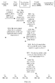
- FIG. 1 is a schematic flowchart of a control method according to an embodiment of the present invention. The method is applied to a wireless communications system, and the wireless communications system includes user equipment, a base station, a gateway device, a local control plane device, and a remote control plane device. As shown in the figure, a process of the control method in this embodiment may include the following steps.
- the local control plane device obtains context information of the user equipment from the remote control plane device according to an interaction process between the user equipment and the remote control plane device.
- the context information of the user equipment includes at least a security context and a bearer context (including a user-plane address and a user-plane TEID-U of an SGW, a TAI (Tracking Area Identity, tracking area identity) list, a GUTI (Globally Unique Temporary Identity, globally unique temporary identity), a control-plane TEID-C allocated by an MME, and a TEID-C allocated by the SGW).
- the TEID (Tunnel Endpoint ID) is a tunnel endpoint identifier.
- the interaction process between the user equipment and the remote control plane device includes an attach request process and a packet data network (Package Data Network, PDN) connection setup process that are initiated by the user equipment.
- PDN Package Data Network
- the local control plane device obtains the context information of the user equipment from the remote control plane device according to the interaction process between the user equipment and the remote control plane device in the following two manners:
- the local control plane device sets up, according to the context information of the user equipment, a radio bearer between the user equipment and a base station in which a current camping cell of the user equipment is located.
- the local control plane device After receiving a service request sent by the user equipment via the base station in which the current camping cell of the user equipment is located, the local control plane device sends a context setup request to the base station according to the context information of the user equipment, so that the base station sets up the radio bearer between the base station and the user equipment.
- sending the service request by the user equipment via the base station in which the current camping cell of the user equipment is located may be triggered by a downlink data arrival notification.
- the local control plane device when the user equipment is in an idle state, the local control plane device initiates paging to the user equipment according to the context information of the user equipment after receiving a downlink data arrival notification message, so that the user equipment switches from the idle state to an active state, and sends the service request via the base station in which the current camping cell is located.
- the source local control plane device and the source gateway device delete the stored context information of the user equipment.
- the source local control plane device after receiving a context deletion request sent by the remote control plane device, deletes the stored context information of the user equipment and sends the context deletion request to the source gateway device, so that the source gateway device deletes the stored context information of the user equipment.
- the source gateway device herein includes a source SGW but does not include a source PGW.
- the local control plane device processes paging and service request processes of the user equipment.
- the local control plane device sends a user state modification notification to the remote control plane device, so that the remote control plane device modifies state information of the user equipment.
- the local control plane device is introduced into an existing wireless network system and has the following functions: a signaling proxy between the base station and the remote control plane device and a signaling proxy between the remote control plane device and the local gateway device.
- the local control plane device may store a bearer context and a security context of a user, and a user TAI list, and is responsible for the paging and service request processes of the user. Other processes are still processed by the remote control plane device in the existing wireless network system.
- some functions of the remote control plane device in the existing wireless network system are deployed in a distributed manner, so that paging and service request functions can be locally implemented. Therefore, a time required for signaling transmission is reduced, a shorter time required for switching from an idle state to an active state is provided for an ultra-low delay application, and an initial packet transmission delay is reduced.
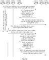
- FIG. 2A , FIG. 2B , and FIG. 2C are a schematic flowchart of a control method according to a first embodiment of the present invention.
- the method is applied to a wireless communications system, and the wireless communications system includes user equipment, a base station, a gateway device, a local control plane device, and a remote control plane device.
- FIG. 10 is a schematic diagram of an architecture of the wireless communications system according to the first embodiment of the present invention.
- a new function entity the local control plane device (Local Control, LC)
- the local control plane device integrates an offloading function with an SGW and a PGW, and is close to an access network.
- an S1 interface is an interface between a remote control plane and the base station
- an S11 interface is an interface between the remote control plane and the SGW.
- a local control plane is a signaling proxy between the two interfaces, serves as an MME for the base station and the SGW, and serves as a base station and an SGW for the remote control plane.
- the gateway device includes the SGW/PGW, and the remote control plane device includes an MME in a conventional network architecture.
- a process of the control method in this embodiment may include the following steps.
- the user equipment sends an attach request to the base station.
- the UE sends the attach request to an eNB to initiate a network attach process.
- the attach request carries an IMSI (International Mobile Subscriber Identification Number, international mobile subscriber identity), a core network capability, a PDN type, and a selected PLMN (Public Land Mobile Network, public land mobile network) of the UE.
- IMSI International Mobile Subscriber Identification Number, international mobile subscriber identity
- PDN type a PDN type
- PLMN Public Land Mobile Network, public land mobile network
- the base station sends the attach request to the local control plane device.
- the eNB sends an S1AP initial UE message to the local control plane device, and the S1AP initial UE message carries the attach request.
- the local control plane device sends the attach request to the remote control plane device.
- the local control plane device sends the attach request to the MME.
- the local control plane device performs authentication on the user equipment and a security setup process.
- the MME performs authentication on the UE and a NAS (Network Attached Storage, network attached storage) security setup process. Subsequently, all NAS messages are protected by a NAS security function indicated by the MME.
- NAS Network Attached Storage, network attached storage
- the remote control plane device sends a session setup request to the local control plane device.
- the MME sends the session setup request to the local control plane device.
- the session setup request includes information such as an EPS bearer identity, an APN (Access Point Name, access point name) of the UE, a control-plane MME TEID, default EPS bearer QoS (Quality of Service, Quality of Service), and a PDN type.
- the local control plane device sends the session setup request to the gateway device.
- the local control plane device forwards the session setup request to the SGW/PGW.
- the gateway device sends a session setup response to the local control plane device.
- the SGW/PGW returns the session setup response.
- the session setup response includes information such as the PDN type, an SGW user-plane address and TEID, an SGW control-plane TEID, the EPS bearer identity, EPS bearer QoS, and a PGW address and TEID.
- the local control plane device sends the session setup response to the remote control plane device.
- the local control plane device forwards the session setup response to the MME.
- the remote control plane device sends an initial context setup request to the base station by using the local control plane device.
- the MME sends the S1AP initial context setup request to the eNB.
- the S1AP initial context setup request carries an attach accept message.
- the S1AP message includes information such as a security context of the UE, the EPS bearer QoS, the EPS bearer identity, and the SGW user-plane address and TEID.
- the attach accept message includes information such as a GUTI, the PDN type, a PDN address, an APN, and a TAI list.
- the base station performs radio resource control connection configuration with the user equipment.
- RRC Radio Resource Control, radio resource control
- the base station sends an initial context setup response to the remote control plane device by using the local control plane device.
- the eNB returns an initial context setup response message.
- the initial context setup response message includes an address and a TEID of an eNB that transmits downlink data on an S1-U interface, and an attach complete message of the UE.
- the remote control plane device sends a bearer modification request to the local control plane device.
- the MME sends the bearer modification request to the local control plane device.
- the bearer modification request includes the EPS bearer identity, and the address and TEID of the eNB.
- the local control plane device obtains context information of the user equipment.
- the local control plane device obtains the context information of the UE from the MME in the following two manners:
- the context information of the UE includes the security context, the bearer context (which already includes a user-plane address, a user-plane TEID-U of the SGW, the TAI list, the GUTI, a control-plane TEID-C allocated by the MME, and a TEID-C allocated by the SGW herein).
- the local control plane device stores this information.
- the local control plane device sends the bearer modification request to the gateway device.
- the local control plane device forwards the bearer modification request to the SGW/PGW.
- the gateway device sends a bearer modification response to the local control plane device.
- the SGW/PGW returns the bearer modification response.
- the bearer modification response carries the EPS bearer identity.
- the local control plane device sends the bearer modification response to the remote control plane device.
- the local control plane device notifies the MME of a bearer modification response message.
- the local control plane device After receiving a downlink data arrival notification message, the local control plane device initiates paging to the user equipment.
- the local control plane device determines stored context information according to the TEID-C allocated by the MME, obtains the TAI list, and sends paging messages to all eNBs in the TAI list to which the UE belongs, where the paging message carries an S-TMSI (some information of the GUTI).
- the eNB initiates paging to the UE.
- the user equipment sends a service request to the local control plane device via the base station.
- the UE responds to the paging message, enters an active state again, and sends the service request to the local control plane device.
- the service request carries the S-TMSI.
- the local control plane device sends a context setup request to the base station.
- the local control plane device finds, according to the S-TMSI, a bearer context (including the EPS bearer QoS, the EPS bearer identity, the SGW user-plane address, and the SGW user-plane TEID-U) and a security context that are correspondingly stored, sends an initial context setup request message to the eNB, sets up a transmission tunnel between the eNB and the SGW/PGW according to the stored bearer context, and sends the security context to the eNB to ensure secure transmission between the UE and the eNB.
- a bearer context including the EPS bearer QoS, the EPS bearer identity, the SGW user-plane address, and the SGW user-plane TEID-U
- a security context that are correspondingly stored
- the base station sends a context setup complete message to the local control plane device.
- the eNB After completing a user-plane radio bearer setup process, the eNB returns an initial context setup complete message to the local control plane device.
- the initial context setup complete message carries an address and a TEID of an eNB that are used to transmit downlink data on the S1 interface, an EPS bearer list accepted by the eNB, and optionally, a rejected EPS bearer list.
- the local control plane device sends the bearer modification request to the SGW/PGW.
- the bearer modification request carries the TEID-C allocated by the SGW, the EPS bearer list (the address and user-plane TEID of the eNB that transmits downlink data on the S1 interface) accepted by the eNB, and optionally, the EPS bearer list rejected by the eNB.
- the local control plane device sends a user state modification notification to the remote control plane device.
- the local control plane device notifies the MME of a latest state of the UE.
- a purpose of this is to avoid repeatedly paging to the UE when the MME needs to convey signaling to the UE.
- the MME needs to delete the EPS bearer rejected on a core network.
- FIG. 3A , FIG. 3B , FIG. 3C , and FIG. 3D are a schematic flowchart of another control method according to a first embodiment of the present invention. As shown in the figure, a process of the control method in this embodiment may include the following steps.
- the UE when the UE performs a cross-domain movement to a new tracking area, the UE sends the TA (Tracking Area, tracking area) update request to an MME to trigger a TA update process.
- TA Tracking Area, tracking area
- the remote control plane device sends a session setup request to a target local control plane device.
- the MME stores context information of the UE and sends the session setup request to the target local control plane device.
- the session setup request carries an MME address, a control-plane TEID, and a bearer context (including an address of a source PGW1).
- the target local control plane device sends the session setup request to a target gateway device.
- the target local control plane device transmits the session setup request to an SGW2.
- the SGW2 sends a bearer modification request according to the address of the PGW1 and sets up an S5 connection from the SGW2 to the PGW1.
- the remote control plane device sends a session deletion request to a source local control plane device.
- the MME sends the session deletion request to the source local control plane device.
- the session deletion request carries a TEID-C allocated by the MME.
- the source local control plane device deletes context information of the user equipment.
- the source local control plane device deletes the corresponding context information according to the TEID-C allocated by the MME.
- the source local control plane device sends the session deletion request to a source gateway device.
- the source local control plane device sends the session deletion request to an SGW1.
- the source gateway device deletes context information of the user equipment.
- the SGW1 deletes the corresponding context information.
- the remote control plane device sends an initial context setup request to a base station by using the target local control plane device.
- the MME sends the initial context (including an SGW user-plane address and TEID-U) setup request to the base station by using the target local control plane device.
- the initial context setup request includes a TA update accept message (a GUTI, a TAI list, and an EPS bearer status).
- the base station performs radio resource control connection configuration with the user equipment.
- the eNB after receiving the initial context setup request, performs RRC connection reconfiguration to set up a radio bearer between the eNB and the UE.
- the UE deletes a local resource of a bearer that is not marked as "active" in the received EPS bearer status, and returns an RRC connection reconfiguration complete message.
- the base station sends an initial context setup response to the remote control plane device.
- the eNB sends the initial context setup response to the MME to return an address and a TEID of an eNB that transmits downlink data on an S1 interface.
- the remote control plane device sends a bearer modification request to the target local control plane device.
- the MME sends the bearer modification request to the target local control plane device.
- the bearer modification request includes an EPS bearer identity, and the address and TEID of the eNB.
- the target local control plane device forwards the bearer modification request to the source gateway device.
- the source gateway device sends a bearer modification response to the target local control plane device.
- the SGW1/PGW1 sends the bearer modification response to the target local control plane device.
- the bearer modification response includes the EPS bearer identity.
- the target local control plane device notifies the MME of the bearer modification response, so that the MME instructs the UE to release a PDN connection between the SGW2 and the PGW1 and delete all bearer contexts in a PDN connection process, and instructs the UE to initiate a PDN connection re-setup process and set up a PDN connection between the local SGW2 and a PGW2.
- the user equipment sends a network connection request to the remote control plane device via the base station.
- the UE sends a PDN connection request to the MME via the eNB.
- the remote control plane device sends a session setup request to the target local control plane device.
- the MME sends the session setup request to the target local control plane device.
- the session setup request includes information such as an address of the target PGW2, the EPS bearer identity, an APN of a user, a control-plane MME TEID-C, default EPS bearer QoS, and a PDN type.
- the target local control plane device sends the session setup request to the target gateway device.
- the target local control plane device transmits a session setup request message to the SGW2.
- the target gateway device sends a session setup response to the target local control plane device.
- the SGW2 sends the bearer modification request according to the address of the PGW2, sets up an S5 connection from the SGW2 to the PGW2, and then returns the session setup response to the target local control plane device.
- the returned session setup response includes information such as a PDN type, an S-GW user-plane address and TEID, an S-GW control-plane TEID, an EPS bearer identity, EPS bearer QoS, and a P-GW address and TEID.
- the remote control plane device sends a bearer setup request to the base station.
- the MME sends the bearer setup request to the UE via the eNB.
- the bearer setup request carries a PDN connection accept message (an APN, the PDN type, a PDN address, and the EPS bearer identity) and includes the EPS bearer QoS and the S-GW user-plane address and TEID.
- the base station performs radio resource control connection configuration with the user equipment.
- RRC connection reconfiguration is completed between the eNB and the UE.
- the base station sends a bearer setup complete message to the remote control plane device.
- the eNB returns the bearer setup complete message to the MME.
- the bearer setup complete message includes an address and a TEID of an eNB that transmits downlink data on S1-U. Then, the UE sends a direct transmission message including a PDN connection complete message to the eNB.
- the eNB sends the bearer setup complete message to the MME.
- the bearer setup complete message carries the PDN connection complete message.
- the remote control plane device sends a bearer modification request to the target local control plane device.
- the MME sends the bearer modification request to the target local control plane device.
- the bearer modification request includes the EPS bearer identity, and the address and TEID of the eNB.
- the target local control plane device obtains the context information of the user equipment.
- the target local control plane device obtains the context information of the UE in the following two manners:
- the context information of the UE includes the security context, the bearer context (which already includes a user-plane address, a user-plane TEID-U of the SGW, the TAI list, the GUTI, a control-plane TEID-C allocated by the MME, and a TEID-C allocated by the SGW herein).
- the local control plane device stores this information.
- the target local control plane device forwards the bearer modification request to the SGW2/PGW2, and further the SGW2/PGW2 returns the bearer modification response including the EPS bearer identity.
- the local control plane is responsible for paging and service request processes and has S1 signaling and S11 signaling proxy functions.
- a signaling transmission path and time are greatly shortened, signaling interaction caused by frequent switching between MMEs in the prior art is avoided, and frequently updating user location information by an HSS caused by mobility of the UE is also avoided.
- FIG. 4A , FIG. 4B , and FIG. 4C are a schematic flowchart of a control method according to a second embodiment of the present invention.
- the method is applied to a wireless communications system, and the wireless communications system includes user equipment, a base station, a gateway device, a local control plane device, and a remote control plane device.
- FIG. 11 is a schematic diagram of an architecture of the wireless communications system according to the second embodiment of the present invention.
- a local control plane device is introduced into the architecture.
- a control plane function (GW-C) and a forwarding plane function (GW-U) of a gateway device are decoupled.
- a control plane function obtained by decoupling, and an MME, a PCRF (Policy and Charging Rules Function, policy and charging rules function), and the like in a conventional network architecture are combined into a remote control plane device that is alternatively referred to as a central control plane device (Central Control, CC).
- Central Control Central Control
- a forwarding plane function (SGW-U) of an SGW and a forwarding plane function (PGW-U) of a PGW are combined into a gateway device (GW-U), and a mobile flow interface is a reference point used after data forwarding of the gateway is separated.
- a process of the control method in this embodiment may include the following steps.
- the user equipment sends an attach request to the base station.
- the UE sends the attach request to an eNB.
- the base station sends the attach request to the local control plane device.
- the eNB sends the attach request to the local control plane device.
- the local control plane device sends the attach request to the remote control plane device.
- the local control plane device forwards the attach request to the remote control plane device, so that authentication is completed between the remote control plane device and the UE.
- the remote control plane device sends an uplink data forwarding rule to the local control plane device.
- the remote control plane device allocates an uplink tunnel identifier, and delivers the uplink data forwarding rule.
- the uplink data forwarding rule includes index information.
- the local control plane device sends the uplink data forwarding rule to the gateway device.
- the local control plane device sends the uplink data forwarding rule to the GW-U, so that the GW-U performs forwarding according to the uplink data forwarding rule.
- the remote control plane device sends an initial context setup request to the base station by using the local control plane device.
- the remote control plane device sends the initial context setup request to the eNB.
- the initial context setup request includes the allocated uplink tunnel identifier.
- the base station performs radio resource control connection configuration with the user equipment.
- RRC connection configuration is completed between the eNB and the UE.
- the base station sends an initial context setup response to the remote control plane device by using the local control plane device.
- the eNB returns the initial context setup response to a control plane.
- the initial context setup response includes a downlink tunnel ID allocated by the eNB and an attach complete message.
- the remote control plane device sends a downlink data forwarding rule to the local control plane device.
- the downlink data forwarding rule includes index information that indicates a manner in which the GW-U sends an IP packet to the UE.
- the local control plane device obtains context information of the user equipment.
- the local control plane device obtains the context information of the UE in the following two manners:
- the context information of the UE includes a UE security context, a bearer context, a TAI list, a GUTI, and index information of uplink and downlink data forwarding rules.
- the local control plane device stores this information.
- the local control plane device sends a downlink data forwarding rule modification message to the gateway device.
- the local control plane device notifies the GW-U of the downlink data forwarding rule.
- the local control plane device After receiving a downlink data arrival notification message, the local control plane device initiates paging to the user equipment.
- the GW-U matches the downlink data forwarding rule, buffers downlink data, and sends the downlink data arrival notification message to the local control plane device.
- the downlink data arrival notification message includes index information corresponding to the downlink data forwarding rule.
- the local control plane device determines a corresponding TAI list of the UE according to the index information of the downlink data forwarding rule, and sends paging messages to all eNBs in the TAI list to which the UE belongs.
- the message carries an S-TMSI (some information of the GUTI), so that the eNB initiates paging to the UE.
- the user equipment sends a service request to the local control plane device via the base station.
- the UE responds to the paging message, enters an active state again, and sends the service request to the local control plane device.
- the service request carries the S-TMSI (some information of the GUTI).
- the local control plane device sends a context setup request to the base station.
- the local control plane device finds, according to the S-TMSI, a bearer context (including EPS bearer QoS, an EPS bearer identity, and the uplink tunnel identifier) and a security context that are correspondingly stored, and sends the initial context setup request to the eNB, so that the eNB sets up a transmission tunnel between the eNB and the GW-U according to the stored bearer context, and sends the security context to the eNB to ensure secure transmission between the UE and the eNB.
- a bearer context including EPS bearer QoS, an EPS bearer identity, and the uplink tunnel identifier
- the base station sends a context setup complete message to the local control plane device.
- the eNB After completing a user-plane radio bearer setup process, the eNB returns the initial context setup complete message.
- the initial context setup complete message includes a tunnel identifier of an eNB that transmits downlink data.
- the local control plane device sends a downlink data forwarding rule modification message to the remote control plane device.
- the local control plane device updates the downlink data forwarding rule of the UE according to a buffered downlink data forwarding rule index, and sets up a transmission tunnel between the eNB and the GW-U, so that the GW-U sends a buffered packet to the eNB.
- the local control plane device sends a user state modification notification to the remote control plane device.
- the local control plane device notifies the remote control plane device of a latest state of the UE.
- FIG. 5A , FIG. 5B , and FIG. 5C are a schematic flowchart of another control method according to a second embodiment of the present invention. As shown in the figure, a process of the control method in this embodiment may include the following steps.
- the UE when the UE performs a cross-domain movement to a new tracking area range, the UE sends the TA update request to the remote control plane device to trigger a TA update process.
- the remote control plane device sends an uplink data forwarding rule to a target local control plane device.
- the remote control plane device allocates an uplink tunnel identifier, and delivers the uplink data forwarding rule to the target local control plane device.
- the uplink data forwarding rule includes index information.
- the target local control plane device sends the uplink data forwarding rule to a target gateway device.
- the target local control plane device instructs a GW-U2 to accept a packet of a tunnel and perform forwarding according to the uplink data forwarding rule.
- the remote control plane device sends a context release command to a source local control plane device.
- the source local control plane device deletes context information of the user equipment.
- the source local control plane device deletes the corresponding context information of the UE according to the context release command.
- the source local control plane device sends the context release command to a source gateway device.
- the source local control plane device sends the context release command to a GW-U1.
- the source gateway device deletes context information of the user equipment.
- the GW-U1 deletes the corresponding context information of the UE according to the context release command.
- the remote control plane device sends an initial context setup request to a base station by using the target local control plane device.
- the remote control plane device sends the initial context setup request to the base station.
- the initial context setup request includes the allocated uplink tunnel identifier, and carries a TAU accept message.
- the TAU accept message includes information such as a GUTI, a PDN type, a PDN address, an APN, and a TAI list.
- the base station performs radio resource control connection configuration with the user equipment.
- the base station sends an initial context setup response to the remote control plane device.
- the eNB returns the initial context setup response to the remote control plane device.
- the initial context setup response includes a downlink tunnel ID allocated by the eNB.
- the remote control plane device sends a downlink data forwarding rule modification message to the target local control plane device.
- the remote control plane device sends the downlink data forwarding rule modification message to the target local control plane device.
- the downlink data forwarding rule modification message includes index information that indicates a manner in which the GW-U sends an IP packet to the UE.
- the target local control plane device forwards the downlink data forwarding rule modification message to the target gateway device.
- the target local control plane device notifies the GW-U2 of the downlink data forwarding rule modification message.
- the user equipment sends a network connection request to the remote control plane device via the base station.
- the remote control plane device instructs the UE to perform PDN connection release and delete all bearers in a source PDN connection process, and instructs the UE to initiate PDN connection re-setup.
- the UE sends the network connection request to the remote control plane device via the eNB.
- the remote control plane device sends a downlink data forwarding rule to the target local control plane device.
- the remote control plane device allocates the uplink tunnel identifier, and delivers the downlink data forwarding rule.
- the downlink data forwarding rule includes index information that indicates a manner in which the GW-U sends an IP packet to the UE.
- the target local control plane device sends the downlink data forwarding rule to the target gateway device.
- the target local control plane device instructs the GW-U2 to accept a packet of a tunnel and perform forwarding according to the downlink data forwarding rule.
- the remote control plane device sends a bearer setup request to the base station.
- the remote control plane device sends the bearer setup request to the eNB.
- the bearer setup request carries a PDN connection accept message (the APN, the PDN type, the PDN address, and the EPS bearer identity), and the PDN connection accept message includes the allocated uplink tunnel identifier.
- the base station performs radio resource control connection configuration with the user equipment.
- the base station sends a bearer setup complete message to the remote control plane device.
- the eNB returns a bearer setup response to the remote control plane device.
- the bearer setup response includes an address and a TEID of an eNB that transmits downlink data on an S1-U interface.
- the UE sends a direct transmission message to the eNB, and the direct transmission message includes a PDN connection complete message.
- the eNB transmits the PDN connection complete message to the remote control plane device.
- the remote control plane device sends a downlink data forwarding rule modification message to the local control plane device.
- the downlink data forwarding rule modification message includes index information that indicates a manner in which the GW-U sends an IP packet to the UE.
- the target local control plane device obtains the context information of the user equipment.
- the target local control plane device obtains the context information of the UE in the following two manners:
- the target local control plane device sends the downlink data forwarding rule modification message to the target gateway device.
- FIG. 6 is a schematic structural diagram of a local control plane device according to an embodiment of the present invention.
- the local control plane device implements the control methods described in FIG. 1 to FIG. 5A , FIG. 5B , and FIG. 5C .
- the local control plane device in this embodiment of the present invention may include at least an information obtaining module 510 and a bearer setup module 520.
- the information obtaining module 510 is configured to obtain context information of a user equipment from a remote control plane device according to an interaction process between the user equipment and the remote control plane device.
- the context information of the user equipment includes at least a security context and a bearer context (including a user-plane address and a user-plane TEID-U of an SGW, a TAI (Tracking Area Identity, tracking area identity) list, a GUTI (Globally Unique Temporary Identity, globally unique temporary identity), a control-plane TEID-C allocated by an MME, and a TEID-C allocated by the SGW).
- the TEID (Tunnel Endpoint ID) is a tunnel endpoint identifier.
- the interaction process between the user equipment and the remote control plane device includes an attach request process and a packet data network (Package Data Network, PDN) connection setup process that are initiated by the user equipment.
- PDN Package Data Network
- the information obtaining module 510 may further include an information forwarding unit 511 and an information obtaining unit 512.
- the information forwarding unit 511 is configured to: in the interaction process between the user equipment and the remote control plane device, forward, to a gateway device, forwarding plane modification information sent by the remote control plane device, where the forwarding plane modification information carries the context information of the user equipment.
- the information obtaining unit 512 is configured to obtain the context information of the user equipment by parsing the forwarding plane modification information.
- the information obtaining module 510 may further include an information forwarding unit 513 and an information receiving unit 514.
- the information forwarding unit 513 is configured to: in the interaction process between the user equipment and the remote control plane device, forward, to the gateway device, forwarding plane modification information sent by the remote control plane device.
- the information receiving unit 514 is configured to receive the context information of the user equipment sent by the remote control plane device.
- the bearer setup module 520 is configured to set up, by the local control plane device according to the context information of the user equipment, a radio bearer between the user equipment and a base station in which a current camping cell of the user equipment is located.
- the bearer setup module 520 sends a context setup request to the base station according to the context information of the user equipment, so that the base station sets up the radio bearer between the base station and the user equipment.
- the local control plane device in this embodiment of the present invention may further include a paging initiation module 530, configured to: after a downlink data arrival notification message is received, initiate paging to the user equipment according to the context information of the user equipment, so that the user equipment switches from an idle state to an active state, and sends the service request via the base station in which the current camping cell is located.
- a paging initiation module 530 configured to: after a downlink data arrival notification message is received, initiate paging to the user equipment according to the context information of the user equipment, so that the user equipment switches from an idle state to an active state, and sends the service request via the base station in which the current camping cell is located.
- the local control plane device in this embodiment of the present invention may further include an information deletion module 540, configured to: after a context deletion request sent by the remote control plane device is received, delete the stored context information of the user equipment; and send the context deletion request to the gateway device, so that the gateway device deletes the stored context information of the user equipment.
- an information deletion module 540 configured to: after a context deletion request sent by the remote control plane device is received, delete the stored context information of the user equipment; and send the context deletion request to the gateway device, so that the gateway device deletes the stored context information of the user equipment.
- the source gateway herein includes a source SGW but does not include a source PGW.
- the local control plane device in this embodiment of the present invention may further include a notification sending module 550, configured to send a user state modification notification to the remote control plane device, so that the remote control plane device modifies state information of the user equipment.
- a notification sending module 550 configured to send a user state modification notification to the remote control plane device, so that the remote control plane device modifies state information of the user equipment.
- FIG. 7 is a schematic structural diagram of another local control plane device according to an embodiment of the present invention.
- the local control plane device may include: at least one processor 601, such as a CPU; at least one network interface 603; a memory 604; and at least one communications bus 602.
- the communications bus 602 is configured to implement connection and communication between these components.
- the network interface 603 may be a wireless interface, such as an antenna apparatus, and is configured to perform signaling or data communication with another node device.
- the memory 604 may be a high-speed RAM memory, or may be a non-volatile memory (non-volatile memory), such as at least one magnetic disk memory.
- the memory 604 may further be at least one storage apparatus located far away from the processor 601.
- the memory 604 stores a group of program code, and the processor 601 is configured to invoke the program code stored in the memory 604 to perform the following operations:
- the interaction process between the user equipment and the remote control plane device includes: an attach request process and a packet data network connection setup process that are initiated by the user equipment.
- a specific operation in which the processor 601 obtains the context information of the user equipment from the remote control plane device according to the interaction process between the user equipment and the remote control plane device is:
- a specific operation in which the processor 601 obtains the context information of the user equipment from the remote control plane device according to the interaction process between the user equipment and the remote control plane device is:
- a specific operation in which the processor 601 sets up, according to the context information of the user equipment, the radio bearer between the user equipment and the base station in which the current camping cell of the user equipment is located is: after receiving a service request sent by the user equipment via the base station in which the current camping cell of the user equipment is located, sending, according to the context information of the user equipment, a context setup request to the base station in which the current camping cell of the user equipment is located, so that the base station in which the current camping cell of the user equipment is located sets up the radio bearer between the base station and the user equipment.
- the processor 601 before receiving the service request sent by the user equipment via the base station in which the current camping cell of the user equipment is located, the processor 601 further performs the following operation: after receiving a downlink data arrival notification message, initiating paging to the user equipment according to the context information of the user equipment, so that the user equipment switches from an idle state to an active state, and sends the service request via the base station in which the current camping cell is located.
- the processor 601 further performs the following operations:
- the processor 601 further performs the following operation: sending a user state modification notification to the remote control plane device, so that the remote control plane device modifies state information of the user equipment.
- the remote control plane device includes:
- the context information of the user equipment includes: a security context of the user equipment and a bearer context of the user equipment, where the bearer context of the user equipment includes a user plane address, a tunnel identifier, a tracking area list, and a globally unique temporary identity of a forwarding plane gateway, and a control plane identifier allocated by the remote control plane device.
- An embodiment of the present invention further proposes a computer storage medium.
- the computer storage medium stores a program, and the program includes several instructions that are used to perform some or all of steps in the control methods described in FIG. 1 to FIG. 5A , FIG. 5B , and FIG. 5C in the embodiments of the present invention.
- the local control plane device obtains the context information of the user equipment from the remote control plane device according to the interaction process between the user equipment and the remote control plane device, and further sets up, according to the context information of the user equipment, the radio bearer between the user equipment and the base station in which the current camping cell of the user equipment is located. Therefore, a signaling transmission delay caused when the user equipment switches from an idle state to an active state can be reduced, and a problem of excessive signaling interaction caused by a movement of the user equipment can be avoided.
- the program may be stored in a computer readable storage medium. When the program runs, the processes of the methods in the embodiments are performed.
- the foregoing storage medium may include: a magnetic disk, an optical disc, a read-only memory (Read-Only Memory, ROM), or a random access memory (Random Access Memory, RAM).
Landscapes
- Engineering & Computer Science (AREA)
- Computer Networks & Wireless Communication (AREA)
- Signal Processing (AREA)
- Mobile Radio Communication Systems (AREA)
Claims (12)
- Steuerungsverfahren, wobei das Verfahren bei einem drahtlosen Kommunikationssystem zum Umschalten eines Benutzer-Equipments aus einem Ruhezustand in einen aktiven Zustand angewandt wird, das drahtlose Kommunikationssystem das Benutzer-Equipment umfasst, das im Ruhezustand ist, eine Basisstation, in der eine aktuelle Zelle des Benutzer-Equipments positioniert ist, eine Gateway-Einrichtung, aufweisend ein aktives Gateway und ein Paketdatennetzwerk-Gateway, eine lokale Steuerebene, die Entladefunktionen mit dem aktiven Gateway und dem Paketdatennetzwerk-Gateway integriert, und eine entfernte Steuerebeneneinrichtung, aufweisend eine Mobilitätsmanagement-Entität,
und das Verfahren umfasst:Erhalten (S101) von Kontextinformation des Benutzer-Equipments von der entfernten Steuerebeneneinrichtung durch die lokale Steuerebeneneinrichtung entsprechend einem Interaktionsprozess zwischen dem Benutzer-Equipment und der entfernten Steuerebeneneinrichtung; undEinrichten (S102) eines Funkträgers zwischen dem Benutzer-Equipment und der Basisstation durch die lokale Steuerebeneneinrichtung entsprechend der Kontextinformation des Benutzer-Equipments, wobei das Einrichten eines Funkträgers zwischen dem Benutzer-Equipment und der Basisstation durch die lokale Steuerebeneneinrichtung entsprechend der Kontextinformation des Benutzer-Equipments umfasst:Nach dem Empfangen einer Dienstanforderung vom Benutzer-Equipment über die Basisstation, in der die aktuelle Zelle des Benutzer-Equipments positioniert ist: Senden einer Kontexteinrichtungsanforderung durch die lokale Steuerebeneneinrichtung entsprechend der Kontextinformation des Benutzer-Equipments zu der Basisstation, in der die aktuelle Zelle des Benutzer-Equipments positioniert ist, sodass die Basisstation, in der die aktuelle Zelle des Benutzer-Equipments positioniert ist, den Funkträger zwischen der Basisstation und dem Benutzer-Equipment einrichtet. - Verfahren nach Anspruch 1, wobei der Interaktionsprozess zwischen dem Benutzer-Equipment und der entfernten Steuerebeneneinrichtung umfasst:
einen Anschlussanforderungsprozess, initiiert durch das Benutzer-Equipment, und einen Paketdatennetzwerkverbindungs-Einrichtungsprozess, initiiert durch das Benutzer-Equipment. - Verfahren nach Anspruch 1, wobei das Erhalten von Kontextinformation des Benutzer-Equipments von der entfernten Steuerebeneneinrichtung durch die lokale Steuerebeneneinrichtung entsprechend einem Interaktionsprozess zwischen dem Benutzer-Equipment und der entfernten Steuerebeneneinrichtung umfasst:In dem Interaktionsprozess zwischen dem Benutzer-Equipment und der entfernten Steuerebeneneinrichtung: Weiterleiten von Weiterleitungsebenen-Änderungsinformation von der entfernten Steuerebeneneinrichtung zu der Gateway-Einrichtung durch die lokale Steuerebeneneinrichtung, wobei die Weiterleitungsebenen-Änderungsinformation die Kontextinformation des Benutzer-Equipments trägt; undErhalten der Kontextinformation des Benutzer-Equipments durch die lokale Steuerebeneneinrichtung mittels Parsing der Weiterleitungsebenen-Änderungsinformation.
- Verfahren nach Anspruch 1, wobei das Erhalten von Kontextinformation des Benutzer-Equipments von der entfernten Steuerebeneneinrichtung durch die lokale Steuerebeneneinrichtung entsprechend einem Interaktionsprozess zwischen dem Benutzer-Equipment und der entfernten Steuerebeneneinrichtung umfasst:In dem Interaktionsprozess zwischen dem Benutzer-Equipment und der entfernten Steuerebeneneinrichtung: Weiterleiten von Weiterleitungsebenen-Änderungsinformation durch die lokale Steuerebeneneinrichtung von der entfernten Steuerebeneneinrichtung zu der Gateway-Einrichtung; undEmpfangen der Kontextinformation des Benutzer-Equipments von der entfernten Steuerebeneneinrichtung durch die lokale Steuerebeneneinrichtung.
- Verfahren nach Anspruch 1, wobei das Verfahren, bevor die lokale Steuerebeneneinrichtung die durch das Benutzer-Equipment über die Basisstation, in der die aktuelle Zelle des Benutzer-Equipments positioniert ist, gesendete Dienstanforderung empfängt, ferner umfasst:
Nach dem Empfangen einer Benachrichtigungsmeldung über das Eintreffen von Downlink-Daten: Initiieren des Paging-Speicherns in das Benutzer-Equipment durch die lokale Steuerebeneneinrichtung entsprechend der Kontextinformation des Benutzer-Equipments, sodass das Benutzer-Equipment aus dem Ruhezustand in den aktiven Zustand wechselt und die Dienstanforderung über die Basisstation, in der die aktuelle Zelle positioniert ist, sendet. - Verfahren nach Anspruch 1, wobei das Verfahren, nach dem Erhalten von Kontextinformation des Benutzer-Equipments von der entfernten Steuerebeneneinrichtung durch die lokale Steuerebeneneinrichtung entsprechend einem Interaktionsprozess zwischen dem Benutzer-Equipment und der entfernten Steuerebeneneinrichtung, ferner umfasst:Nach dem Empfangen einer Kontextlöschanforderung von der entfernten Steuerebeneneinrichtung: Löschen der gespeicherten Kontextinformation des Benutzer-Equipments durch die lokale Steuerebeneneinrichtung; undSenden der Kontextlöschanforderung durch die lokale Steuerebeneneinrichtung zu der Gateway-Einrichtung, sodass die Gateway-Einrichtung die gespeicherte Kontextinformation des Benutzer-Equipments löscht.
- Verfahren nach Anspruch 1, wobei das Verfahren nach dem Einrichten eines Funkträgers durch die lokale Steuerebeneneinrichtung entsprechend der Kontextinformation des Benutzer-Equipments zwischen dem Benutzer-Equipment und einer Basisstation, in der eine aktuelle Aufenthaltszelle des Benutzer-Equipments positioniert ist, ferner umfasst:
Senden einer Benutzerstatus-Änderungsbenachrichtigung durch die lokale Steuerebeneneinrichtung zur entfernten Steuerebeneneinrichtung, sodass die entfernte Steuerebeneneinrichtung die Statusinformation des Benutzer-Equipments ändert. - Lokale Steuerebeneneinrichtung, wobei die lokale Steuerebeneneinrichtung Entladefunktionen mit einem aktiven Gateway und einem Paketdatennetzwerk-Gateway integriert und auf ein drahtloses Kommunikationssystem zum Umschalten einer Benutzer-Einrichtung aus einem Ruhezustand in einen aktiven Zustand angewandt wird, das drahtlose Kommunikationssystem ferner das Benutzer-Equipment, das in einem Ruhezustand ist, eine Basisstation, in der eine aktuelle Zelle des Benutzer-Equipments positioniert ist, eine Gateway-Einrichtung, aufweisend das Paketdatennetzwerk-Gateway, und das Paketdatennetzwerk-Gateway und eine entfernte Steuerebeneneinrichtung, aufweisend eine Mobilitätsmanagement-Entität, umfasst und die lokale Steuerebeneneinrichtung umfasst:ein Informationserhaltmodul (510), ausgelegt zum Erhalten von Kontextinformation des Benutzer-Equipments von der entfernten Steuerebeneneinrichtung entsprechend einem Interaktionsprozess zwischen dem Benutzer-Equipment und der entfernten Steuerebeneneinrichtung; undein Träger-Einrichtungsmodul (520), ausgelegt zum Einrichten eines Funkträgers zwischen dem Benutzer-Equipment und der Basisstation entsprechend der Kontextinformation des Benutzer-Equipments, wobei das Träger-Einrichtungsmodul im Einzelnen dafür ausgelegt ist, nachdem eine Dienstanforderung von dem Benutzer-Equipment über die Basisstation, in der die aktuelle Zelle des Benutzer-Equipments positioniert ist, empfangen worden ist, entsprechend der Kontextinformation des Benutzer-Equipments eine Kontext-Einrichtungsanforderung zu der Basisstation zu senden, in der die aktuelle Zelle des Benutzer-Equipments positioniert ist, sodass die Basisstation, in der die aktuelle Zelle des Benutzer-Equipments positioniert ist, den Funkträger zwischen der Basisstation und dem Benutzer-Equipment einrichtet.
- Lokale Steuerebeneneinrichtung nach Anspruch 8, wobei der Interaktionsprozess zwischen dem Benutzer-Equipment und der entfernten Steuerebeneneinrichtung umfasst:
einen Anschlussanforderungsprozess, initiiert durch das Benutzer-Equipment, und einen Paketdatennetzwerkverbindungs-Einrichtungsprozess, initiiert durch das Benutzer-Equipment. - Lokale Steuerebeneneinrichtung nach Anspruch 8, wobei das Informationserhaltmodul umfasst:eine Informationsweiterleitungseinheit (511), dafür ausgelegt, in dem Interaktionsprozess zwischen dem Benutzer-Equipment und der entfernten Steuerebeneneinrichtung Weiterleitungsebenen-Änderungsinformation von der entfernten Steuerebeneneinrichtung zu der Gateway-Einrichtung weiterzuleiten, wobei die Weiterleitungsebenen-Änderungsinformation die Kontextinformation des Benutzer-Equipments trägt; undeine Informationserhalteinheit (512), ausgelegt zum Erhalten der Kontextinformation des Benutzer-Equipments mittels Parsings der Weiterleitungsebenen-Änderungsinformation.
- Lokale Steuerebeneneinrichtung nach Anspruch 8, wobei das Informationserhaltmodul umfasst:eine Informationsweiterleitungseinheit (513), dafür ausgelegt, in dem Interaktionsprozess zwischen dem Benutzer-Equipment und der entfernten Steuerebeneneinrichtung Weiterleitungsebenen-Änderungsinformation von der entfernten Steuerebeneneinrichtung zu der Gateway-Einrichtung weiterzuleiten; undeine Informationserhalteinheit (514), ausgelegt zum Erhalten der Kontextinformation des Benutzer-Equipments von der entfernten Steuerebeneneinrichtung.
- Lokale Steuerebeneneinrichtung nach Anspruch 8, wobei die lokale Steuerebeneneinrichtung ferner umfasst:
ein Paging-Initiierungsmodul (530), dafür ausgelegt, nachdem eine Benachrichtigungsmeldung über das Eintreffen von Downlink-Daten empfangen worden ist, das Paging-Speichern in das Benutzer-Equipment entsprechend der Kontextinformation des Benutzer-Equipments zu initiieren, sodass das Benutzer-Equipment aus einem Ruhezustand in einen aktiven Zustand wechselt und die Dienstanforderung über die Basisstation, in der die aktuelle Zelle positioniert ist, sendet.
Priority Applications (1)
| Application Number | Priority Date | Filing Date | Title |
|---|---|---|---|
| EP19189923.6A EP3629669B1 (de) | 2015-09-22 | 2015-09-22 | Steuerungsverfahren,lokale vorrichtung auf steuerebene, system und computer lesbares medium zum umschalten einer benutzerendgerätes von einem idle status zu einem activen status |
Applications Claiming Priority (1)
| Application Number | Priority Date | Filing Date | Title |
|---|---|---|---|
| PCT/CN2015/090270 WO2017049458A1 (zh) | 2015-09-22 | 2015-09-22 | 一种控制方法及本地控制面设备 |
Related Child Applications (1)
| Application Number | Title | Priority Date | Filing Date |
|---|---|---|---|
| EP19189923.6A Division EP3629669B1 (de) | 2015-09-22 | 2015-09-22 | Steuerungsverfahren,lokale vorrichtung auf steuerebene, system und computer lesbares medium zum umschalten einer benutzerendgerätes von einem idle status zu einem activen status |
Publications (3)
| Publication Number | Publication Date |
|---|---|
| EP3334236A1 EP3334236A1 (de) | 2018-06-13 |
| EP3334236A4 EP3334236A4 (de) | 2018-08-22 |
| EP3334236B1 true EP3334236B1 (de) | 2019-09-04 |
Family
ID=58385466
Family Applications (2)
| Application Number | Title | Priority Date | Filing Date |
|---|---|---|---|
| EP15904346.2A Active EP3334236B1 (de) | 2015-09-22 | 2015-09-22 | Steuerungsverfahren und lokale vorrichtung auf steuerebene |
| EP19189923.6A Active EP3629669B1 (de) | 2015-09-22 | 2015-09-22 | Steuerungsverfahren,lokale vorrichtung auf steuerebene, system und computer lesbares medium zum umschalten einer benutzerendgerätes von einem idle status zu einem activen status |
Family Applications After (1)
| Application Number | Title | Priority Date | Filing Date |
|---|---|---|---|
| EP19189923.6A Active EP3629669B1 (de) | 2015-09-22 | 2015-09-22 | Steuerungsverfahren,lokale vorrichtung auf steuerebene, system und computer lesbares medium zum umschalten einer benutzerendgerätes von einem idle status zu einem activen status |
Country Status (6)
| Country | Link |
|---|---|
| US (2) | US10506648B2 (de) |
| EP (2) | EP3334236B1 (de) |
| CN (2) | CN111726888B (de) |
| BR (1) | BR112018004604B1 (de) |
| MY (1) | MY189130A (de) |
| WO (1) | WO2017049458A1 (de) |
Families Citing this family (5)
| Publication number | Priority date | Publication date | Assignee | Title |
|---|---|---|---|---|
| EP3913867A1 (de) * | 2016-01-15 | 2021-11-24 | NEC Corporation | Kommunikationssystem und kommunikationsverfahren |
| CN108476549B (zh) * | 2016-01-19 | 2021-03-30 | 华为技术有限公司 | 一种ip地址分配方法及设备 |
| KR101893917B1 (ko) * | 2016-01-25 | 2018-08-31 | 에스케이 텔레콤주식회사 | 기능 분리된 코어 네트워크에서 하향링크 패킷 전송방법 |
| US11178729B2 (en) * | 2016-11-03 | 2021-11-16 | Guangdong Oppo Mobile Telecommunications Corp., Ltd. | Method for switching communication mode, and terminal device and network device |
| US10531388B2 (en) * | 2017-02-06 | 2020-01-07 | Qualcomm Incorporated | Data transmission in inactive state |
Family Cites Families (12)
| Publication number | Priority date | Publication date | Assignee | Title |
|---|---|---|---|---|
| US10893556B2 (en) * | 2009-04-30 | 2021-01-12 | Samsung Electronics Co., Ltd | Method and apparatus for supporting local IP access in a femto cell of a wireless communication system |
| CN101998567B (zh) * | 2009-08-21 | 2014-09-10 | 中兴通讯股份有限公司 | 终端转为连接态时更改服务网关的连接激活方法及系统 |
| EP2604052B1 (de) * | 2010-08-09 | 2014-10-08 | NEC Europe Ltd. | Vorrichtung und verfahren für lokale mobilitätsverwaltung in einem cluster-femtozellennetzwerk |
| US9167623B2 (en) * | 2010-09-09 | 2015-10-20 | Panasonic Intellectual Property Corporation Of America | Communication system, communication method, mobile terminal, and mobile base station device |
| EP2509374A1 (de) * | 2011-04-05 | 2012-10-10 | Panasonic Corporation | Ablösung eines mobilen Endgerätes (MTC) von einem mobilen Kommunikationssystem |
| CN102843779B (zh) * | 2011-06-22 | 2017-03-22 | 中兴通讯股份有限公司 | 连接的建立处理方法及装置 |
| CN102986261B (zh) * | 2011-07-15 | 2015-11-25 | 华为技术有限公司 | 处理寻呼的方法、用户设备和系统 |
| CN102427599B (zh) * | 2011-08-12 | 2015-04-08 | 电信科学技术研究院 | 数据传输方法和设备 |
| CN102724769B (zh) * | 2012-01-10 | 2018-03-27 | 中兴通讯股份有限公司 | 一种本地访问连接的处理方法和装置 |
| CN103546985A (zh) * | 2012-07-17 | 2014-01-29 | 普天信息技术研究院有限公司 | 一种ue发起承载资源分配的方法 |
| ES2786003T3 (es) * | 2012-09-18 | 2020-10-08 | Alcatel Lucent | Soporte de usuarios nómadas o fijos en una red móvil |
| WO2017080622A1 (en) * | 2015-11-13 | 2017-05-18 | Telefonaktiebolaget Lm Ericsson (Publ) | Node and method for managing a packet data network connection and/or an internet protocol - connectivity access network session |
-
2015
- 2015-09-22 EP EP15904346.2A patent/EP3334236B1/de active Active
- 2015-09-22 CN CN202010392419.1A patent/CN111726888B/zh active Active
- 2015-09-22 BR BR112018004604-3A patent/BR112018004604B1/pt active IP Right Grant
- 2015-09-22 CN CN201580082315.8A patent/CN107926064B/zh active Active
- 2015-09-22 EP EP19189923.6A patent/EP3629669B1/de active Active
- 2015-09-22 WO PCT/CN2015/090270 patent/WO2017049458A1/zh not_active Ceased
- 2015-09-22 MY MYPI2018700807A patent/MY189130A/en unknown
-
2018
- 2018-02-28 US US15/908,225 patent/US10506648B2/en active Active
-
2019
- 2019-10-24 US US16/663,044 patent/US11096227B2/en active Active
Non-Patent Citations (1)
| Title |
|---|
| None * |
Also Published As
| Publication number | Publication date |
|---|---|
| WO2017049458A1 (zh) | 2017-03-30 |
| US20200092924A1 (en) | 2020-03-19 |
| EP3629669A1 (de) | 2020-04-01 |
| EP3334236A4 (de) | 2018-08-22 |
| US11096227B2 (en) | 2021-08-17 |
| CN111726888B (zh) | 2024-06-04 |
| EP3334236A1 (de) | 2018-06-13 |
| EP3629669B1 (de) | 2022-11-02 |
| US10506648B2 (en) | 2019-12-10 |
| BR112018004604A2 (pt) | 2018-09-25 |
| CN107926064B (zh) | 2020-06-16 |
| CN107926064A (zh) | 2018-04-17 |
| BR112018004604B1 (pt) | 2023-10-03 |
| US20180192456A1 (en) | 2018-07-05 |
| MY189130A (en) | 2022-01-27 |
| CN111726888A (zh) | 2020-09-29 |
Similar Documents
| Publication | Publication Date | Title |
|---|---|---|
| JP6985455B2 (ja) | 無線通信システムにおけるネットワーク間の相互連動方法及びそのための装置 | |
| US11096227B2 (en) | Control method and local control plane device | |
| CN109155909B (zh) | 无线通信系统中用于更新ue配置的方法及其装置 | |
| EP3373523B1 (de) | Verfahren, vorrichtung und system zur umschaltung zwischen mobile-edge-datenverarbeitungsplattformen | |
| CN111510986B (zh) | 保持业务连续性的方法、控制面网关和移动管理网元 | |
| EP2736282B1 (de) | Verfahren, system und sgw zur realisierung einer ip-adressattributmeldung | |
| US10455459B2 (en) | Method and apparatus for establishing session for data transmission and reception in wireless communication system | |
| CN106664730B (zh) | 一种无线通信系统的管理方法和相关装置 | |
| EP3547755A1 (de) | Umschaltverfahren, endgerätevorrichtung und netzwerkvorrichtung | |
| EP3573360A1 (de) | Datenübertragungsverfahren, basisstation, local-breakout-steuergerät, gateway und system | |
| EP3512223B1 (de) | Sitzungsverwaltungsverfahren und netzwerkelement | |
| EP3324677B1 (de) | Änderung eines netzwerkzugriffs einer terminal von einem zugriff über ein relay terminal zu einer direkt zugriff | |
| CN106714133A (zh) | 网关的恢复处理方法及装置 | |
| CN115604757A (zh) | 用于拥塞处理的方法和设备 | |
| EP3291610B1 (de) | Selektive priorisierung eines lokalen oder globalen kernnetzes | |
| CN101621786B (zh) | 一种承载更新的方法、装置和系统 | |
| EP3567886B1 (de) | Verfahren und vorrichtung zur downlink-datenübertragung | |
| KR101654066B1 (ko) | 무선 통신 시스템의 사용자 선호 기반 접속 망 결정 방법 | |
| CN102413588A (zh) | 释放分组数据网连接的处理方法及系统 |
Legal Events
| Date | Code | Title | Description |
|---|---|---|---|
| STAA | Information on the status of an ep patent application or granted ep patent |
Free format text: STATUS: THE INTERNATIONAL PUBLICATION HAS BEEN MADE |
|
| PUAI | Public reference made under article 153(3) epc to a published international application that has entered the european phase |
Free format text: ORIGINAL CODE: 0009012 |
|
| STAA | Information on the status of an ep patent application or granted ep patent |
Free format text: STATUS: REQUEST FOR EXAMINATION WAS MADE |
|
| 17P | Request for examination filed |
Effective date: 20180306 |
|
| AK | Designated contracting states |
Kind code of ref document: A1 Designated state(s): AL AT BE BG CH CY CZ DE DK EE ES FI FR GB GR HR HU IE IS IT LI LT LU LV MC MK MT NL NO PL PT RO RS SE SI SK SM TR |
|
| AX | Request for extension of the european patent |
Extension state: BA ME |
|
| A4 | Supplementary search report drawn up and despatched |
Effective date: 20180719 |
|
| RIC1 | Information provided on ipc code assigned before grant |
Ipc: H04W 72/04 20090101ALN20180713BHEP Ipc: H04W 76/11 20180101ALI20180713BHEP Ipc: H04W 28/08 20090101ALI20180713BHEP Ipc: H04W 76/14 20180101ALI20180713BHEP Ipc: H04W 88/16 20090101ALI20180713BHEP Ipc: H04W 8/08 20090101ALI20180713BHEP Ipc: H04W 76/12 20180101ALI20180713BHEP Ipc: H04W 76/10 20180101AFI20180713BHEP |
|
| DAV | Request for validation of the european patent (deleted) | ||
| DAX | Request for extension of the european patent (deleted) | ||
| RIC1 | Information provided on ipc code assigned before grant |
Ipc: H04W 76/14 20180101ALI20190114BHEP Ipc: H04W 72/04 20090101ALN20190114BHEP Ipc: H04W 76/11 20180101ALI20190114BHEP Ipc: H04W 8/08 20090101ALI20190114BHEP Ipc: H04W 28/08 20090101ALI20190114BHEP Ipc: H04W 76/12 20180101ALI20190114BHEP Ipc: H04W 76/10 20180101AFI20190114BHEP Ipc: H04W 88/16 20090101ALI20190114BHEP |
|
| REG | Reference to a national code |
Ref country code: DE Ref legal event code: R079 Ref document number: 602015037563 Country of ref document: DE Free format text: PREVIOUS MAIN CLASS: H04W0076020000 Ipc: H04W0076100000 |
|
| GRAP | Despatch of communication of intention to grant a patent |
Free format text: ORIGINAL CODE: EPIDOSNIGR1 |
|
| STAA | Information on the status of an ep patent application or granted ep patent |
Free format text: STATUS: GRANT OF PATENT IS INTENDED |
|
| INTG | Intention to grant announced |
Effective date: 20190318 |
|
| RIC1 | Information provided on ipc code assigned before grant |
Ipc: H04W 76/14 20180101ALI20190306BHEP Ipc: H04W 76/10 20180101AFI20190306BHEP Ipc: H04W 76/11 20180101ALI20190306BHEP Ipc: H04W 8/08 20090101ALI20190306BHEP Ipc: H04W 76/12 20180101ALI20190306BHEP Ipc: H04W 88/16 20090101ALI20190306BHEP Ipc: H04W 28/08 20090101ALI20190306BHEP Ipc: H04W 72/04 20090101ALN20190306BHEP |
|
| GRAS | Grant fee paid |
Free format text: ORIGINAL CODE: EPIDOSNIGR3 |
|
| GRAA | (expected) grant |
Free format text: ORIGINAL CODE: 0009210 |
|
| STAA | Information on the status of an ep patent application or granted ep patent |
Free format text: STATUS: THE PATENT HAS BEEN GRANTED |
|
| AK | Designated contracting states |
Kind code of ref document: B1 Designated state(s): AL AT BE BG CH CY CZ DE DK EE ES FI FR GB GR HR HU IE IS IT LI LT LU LV MC MK MT NL NO PL PT RO RS SE SI SK SM TR |
|
| REG | Reference to a national code |
Ref country code: GB Ref legal event code: FG4D |
|
| REG | Reference to a national code |
Ref country code: CH Ref legal event code: EP |
|
| REG | Reference to a national code |
Ref country code: AT Ref legal event code: REF Ref document number: 1177233 Country of ref document: AT Kind code of ref document: T Effective date: 20190915 |
|
| REG | Reference to a national code |
Ref country code: DE Ref legal event code: R096 Ref document number: 602015037563 Country of ref document: DE Ref country code: IE Ref legal event code: FG4D |
|
| REG | Reference to a national code |
Ref country code: NL Ref legal event code: MP Effective date: 20190904 |
|
| REG | Reference to a national code |
Ref country code: LT Ref legal event code: MG4D |
|
| PG25 | Lapsed in a contracting state [announced via postgrant information from national office to epo] |
Ref country code: NO Free format text: LAPSE BECAUSE OF FAILURE TO SUBMIT A TRANSLATION OF THE DESCRIPTION OR TO PAY THE FEE WITHIN THE PRESCRIBED TIME-LIMIT Effective date: 20191204 Ref country code: BG Free format text: LAPSE BECAUSE OF FAILURE TO SUBMIT A TRANSLATION OF THE DESCRIPTION OR TO PAY THE FEE WITHIN THE PRESCRIBED TIME-LIMIT Effective date: 20191204 Ref country code: SE Free format text: LAPSE BECAUSE OF FAILURE TO SUBMIT A TRANSLATION OF THE DESCRIPTION OR TO PAY THE FEE WITHIN THE PRESCRIBED TIME-LIMIT Effective date: 20190904 Ref country code: FI Free format text: LAPSE BECAUSE OF FAILURE TO SUBMIT A TRANSLATION OF THE DESCRIPTION OR TO PAY THE FEE WITHIN THE PRESCRIBED TIME-LIMIT Effective date: 20190904 Ref country code: HR Free format text: LAPSE BECAUSE OF FAILURE TO SUBMIT A TRANSLATION OF THE DESCRIPTION OR TO PAY THE FEE WITHIN THE PRESCRIBED TIME-LIMIT Effective date: 20190904 Ref country code: LT Free format text: LAPSE BECAUSE OF FAILURE TO SUBMIT A TRANSLATION OF THE DESCRIPTION OR TO PAY THE FEE WITHIN THE PRESCRIBED TIME-LIMIT Effective date: 20190904 |
|
| PG25 | Lapsed in a contracting state [announced via postgrant information from national office to epo] |
Ref country code: ES Free format text: LAPSE BECAUSE OF FAILURE TO SUBMIT A TRANSLATION OF THE DESCRIPTION OR TO PAY THE FEE WITHIN THE PRESCRIBED TIME-LIMIT Effective date: 20190904 Ref country code: GR Free format text: LAPSE BECAUSE OF FAILURE TO SUBMIT A TRANSLATION OF THE DESCRIPTION OR TO PAY THE FEE WITHIN THE PRESCRIBED TIME-LIMIT Effective date: 20191205 Ref country code: RS Free format text: LAPSE BECAUSE OF FAILURE TO SUBMIT A TRANSLATION OF THE DESCRIPTION OR TO PAY THE FEE WITHIN THE PRESCRIBED TIME-LIMIT Effective date: 20190904 Ref country code: LV Free format text: LAPSE BECAUSE OF FAILURE TO SUBMIT A TRANSLATION OF THE DESCRIPTION OR TO PAY THE FEE WITHIN THE PRESCRIBED TIME-LIMIT Effective date: 20190904 Ref country code: AL Free format text: LAPSE BECAUSE OF FAILURE TO SUBMIT A TRANSLATION OF THE DESCRIPTION OR TO PAY THE FEE WITHIN THE PRESCRIBED TIME-LIMIT Effective date: 20190904 |
|
| REG | Reference to a national code |
Ref country code: AT Ref legal event code: MK05 Ref document number: 1177233 Country of ref document: AT Kind code of ref document: T Effective date: 20190904 |
|
| REG | Reference to a national code |
Ref country code: DE Ref legal event code: R119 Ref document number: 602015037563 Country of ref document: DE |
|
| PG25 | Lapsed in a contracting state [announced via postgrant information from national office to epo] |
Ref country code: PT Free format text: LAPSE BECAUSE OF FAILURE TO SUBMIT A TRANSLATION OF THE DESCRIPTION OR TO PAY THE FEE WITHIN THE PRESCRIBED TIME-LIMIT Effective date: 20200106 Ref country code: PL Free format text: LAPSE BECAUSE OF FAILURE TO SUBMIT A TRANSLATION OF THE DESCRIPTION OR TO PAY THE FEE WITHIN THE PRESCRIBED TIME-LIMIT Effective date: 20190904 Ref country code: RO Free format text: LAPSE BECAUSE OF FAILURE TO SUBMIT A TRANSLATION OF THE DESCRIPTION OR TO PAY THE FEE WITHIN THE PRESCRIBED TIME-LIMIT Effective date: 20190904 Ref country code: IT Free format text: LAPSE BECAUSE OF FAILURE TO SUBMIT A TRANSLATION OF THE DESCRIPTION OR TO PAY THE FEE WITHIN THE PRESCRIBED TIME-LIMIT Effective date: 20190904 Ref country code: NL Free format text: LAPSE BECAUSE OF FAILURE TO SUBMIT A TRANSLATION OF THE DESCRIPTION OR TO PAY THE FEE WITHIN THE PRESCRIBED TIME-LIMIT Effective date: 20190904 Ref country code: EE Free format text: LAPSE BECAUSE OF FAILURE TO SUBMIT A TRANSLATION OF THE DESCRIPTION OR TO PAY THE FEE WITHIN THE PRESCRIBED TIME-LIMIT Effective date: 20190904 Ref country code: AT Free format text: LAPSE BECAUSE OF FAILURE TO SUBMIT A TRANSLATION OF THE DESCRIPTION OR TO PAY THE FEE WITHIN THE PRESCRIBED TIME-LIMIT Effective date: 20190904 |
|
| PG25 | Lapsed in a contracting state [announced via postgrant information from national office to epo] |
Ref country code: IS Free format text: LAPSE BECAUSE OF FAILURE TO SUBMIT A TRANSLATION OF THE DESCRIPTION OR TO PAY THE FEE WITHIN THE PRESCRIBED TIME-LIMIT Effective date: 20200224 Ref country code: CZ Free format text: LAPSE BECAUSE OF FAILURE TO SUBMIT A TRANSLATION OF THE DESCRIPTION OR TO PAY THE FEE WITHIN THE PRESCRIBED TIME-LIMIT Effective date: 20190904 Ref country code: SM Free format text: LAPSE BECAUSE OF FAILURE TO SUBMIT A TRANSLATION OF THE DESCRIPTION OR TO PAY THE FEE WITHIN THE PRESCRIBED TIME-LIMIT Effective date: 20190904 Ref country code: SK Free format text: LAPSE BECAUSE OF FAILURE TO SUBMIT A TRANSLATION OF THE DESCRIPTION OR TO PAY THE FEE WITHIN THE PRESCRIBED TIME-LIMIT Effective date: 20190904 |
|
| REG | Reference to a national code |
Ref country code: CH Ref legal event code: PL |
|
| PLBE | No opposition filed within time limit |
Free format text: ORIGINAL CODE: 0009261 |
|
| STAA | Information on the status of an ep patent application or granted ep patent |
Free format text: STATUS: NO OPPOSITION FILED WITHIN TIME LIMIT |
|
| PG2D | Information on lapse in contracting state deleted |
Ref country code: IS |
|
| PG25 | Lapsed in a contracting state [announced via postgrant information from national office to epo] |
Ref country code: DE Free format text: LAPSE BECAUSE OF NON-PAYMENT OF DUE FEES Effective date: 20200401 Ref country code: DK Free format text: LAPSE BECAUSE OF FAILURE TO SUBMIT A TRANSLATION OF THE DESCRIPTION OR TO PAY THE FEE WITHIN THE PRESCRIBED TIME-LIMIT Effective date: 20190904 Ref country code: LI Free format text: LAPSE BECAUSE OF NON-PAYMENT OF DUE FEES Effective date: 20190930 Ref country code: CH Free format text: LAPSE BECAUSE OF NON-PAYMENT OF DUE FEES Effective date: 20190930 Ref country code: LU Free format text: LAPSE BECAUSE OF NON-PAYMENT OF DUE FEES Effective date: 20190922 Ref country code: IE Free format text: LAPSE BECAUSE OF NON-PAYMENT OF DUE FEES Effective date: 20190922 Ref country code: IS Free format text: LAPSE BECAUSE OF FAILURE TO SUBMIT A TRANSLATION OF THE DESCRIPTION OR TO PAY THE FEE WITHIN THE PRESCRIBED TIME-LIMIT Effective date: 20200105 |
|
| REG | Reference to a national code |
Ref country code: BE Ref legal event code: MM Effective date: 20190930 |
|
| 26N | No opposition filed |
Effective date: 20200605 |
|
| PG25 | Lapsed in a contracting state [announced via postgrant information from national office to epo] |
Ref country code: SI Free format text: LAPSE BECAUSE OF FAILURE TO SUBMIT A TRANSLATION OF THE DESCRIPTION OR TO PAY THE FEE WITHIN THE PRESCRIBED TIME-LIMIT Effective date: 20190904 Ref country code: MC Free format text: LAPSE BECAUSE OF FAILURE TO SUBMIT A TRANSLATION OF THE DESCRIPTION OR TO PAY THE FEE WITHIN THE PRESCRIBED TIME-LIMIT Effective date: 20190904 Ref country code: BE Free format text: LAPSE BECAUSE OF NON-PAYMENT OF DUE FEES Effective date: 20190930 |
|
| PG25 | Lapsed in a contracting state [announced via postgrant information from national office to epo] |
Ref country code: FR Free format text: LAPSE BECAUSE OF NON-PAYMENT OF DUE FEES Effective date: 20191104 |
|
| PG25 | Lapsed in a contracting state [announced via postgrant information from national office to epo] |
Ref country code: CY Free format text: LAPSE BECAUSE OF FAILURE TO SUBMIT A TRANSLATION OF THE DESCRIPTION OR TO PAY THE FEE WITHIN THE PRESCRIBED TIME-LIMIT Effective date: 20190904 |
|
| PG25 | Lapsed in a contracting state [announced via postgrant information from national office to epo] |
Ref country code: MT Free format text: LAPSE BECAUSE OF FAILURE TO SUBMIT A TRANSLATION OF THE DESCRIPTION OR TO PAY THE FEE WITHIN THE PRESCRIBED TIME-LIMIT Effective date: 20190904 Ref country code: HU Free format text: LAPSE BECAUSE OF FAILURE TO SUBMIT A TRANSLATION OF THE DESCRIPTION OR TO PAY THE FEE WITHIN THE PRESCRIBED TIME-LIMIT; INVALID AB INITIO Effective date: 20150922 |
|
| PG25 | Lapsed in a contracting state [announced via postgrant information from national office to epo] |
Ref country code: TR Free format text: LAPSE BECAUSE OF FAILURE TO SUBMIT A TRANSLATION OF THE DESCRIPTION OR TO PAY THE FEE WITHIN THE PRESCRIBED TIME-LIMIT Effective date: 20190904 |
|
| PG25 | Lapsed in a contracting state [announced via postgrant information from national office to epo] |
Ref country code: MK Free format text: LAPSE BECAUSE OF FAILURE TO SUBMIT A TRANSLATION OF THE DESCRIPTION OR TO PAY THE FEE WITHIN THE PRESCRIBED TIME-LIMIT Effective date: 20190904 |
|
| PGFP | Annual fee paid to national office [announced via postgrant information from national office to epo] |
Ref country code: GB Payment date: 20250731 Year of fee payment: 11 |