EP3334013A1 - Housing and motor including same - Google Patents
Housing and motor including same Download PDFInfo
- Publication number
- EP3334013A1 EP3334013A1 EP16833297.1A EP16833297A EP3334013A1 EP 3334013 A1 EP3334013 A1 EP 3334013A1 EP 16833297 A EP16833297 A EP 16833297A EP 3334013 A1 EP3334013 A1 EP 3334013A1
- Authority
- EP
- European Patent Office
- Prior art keywords
- teeth
- support part
- stator
- housing
- end surfaces
- Prior art date
- Legal status (The legal status is an assumption and is not a legal conclusion. Google has not performed a legal analysis and makes no representation as to the accuracy of the status listed.)
- Granted
Links
Images



Classifications
-
- H—ELECTRICITY
- H02—GENERATION; CONVERSION OR DISTRIBUTION OF ELECTRIC POWER
- H02K—DYNAMO-ELECTRIC MACHINES
- H02K3/00—Details of windings
- H02K3/46—Fastening of windings on the stator or rotor structure
- H02K3/48—Fastening of windings on the stator or rotor structure in slots
- H02K3/487—Slot-closing devices
-
- H—ELECTRICITY
- H02—GENERATION; CONVERSION OR DISTRIBUTION OF ELECTRIC POWER
- H02K—DYNAMO-ELECTRIC MACHINES
- H02K1/00—Details of the magnetic circuit
- H02K1/06—Details of the magnetic circuit characterised by the shape, form or construction
- H02K1/12—Stationary parts of the magnetic circuit
- H02K1/18—Means for mounting or fastening magnetic stationary parts on to, or to, the stator structures
- H02K1/185—Means for mounting or fastening magnetic stationary parts on to, or to, the stator structures to outer stators
-
- H—ELECTRICITY
- H02—GENERATION; CONVERSION OR DISTRIBUTION OF ELECTRIC POWER
- H02K—DYNAMO-ELECTRIC MACHINES
- H02K5/00—Casings; Enclosures; Supports
- H02K5/04—Casings or enclosures characterised by the shape, form or construction thereof
-
- H—ELECTRICITY
- H02—GENERATION; CONVERSION OR DISTRIBUTION OF ELECTRIC POWER
- H02K—DYNAMO-ELECTRIC MACHINES
- H02K5/00—Casings; Enclosures; Supports
- H02K5/04—Casings or enclosures characterised by the shape, form or construction thereof
- H02K5/16—Means for supporting bearings, e.g. insulating supports or means for fitting bearings in the bearing-shields
- H02K5/163—Means for supporting bearings, e.g. insulating supports or means for fitting bearings in the bearing-shields radially supporting the rotary shaft at only one end of the rotor
-
- H—ELECTRICITY
- H02—GENERATION; CONVERSION OR DISTRIBUTION OF ELECTRIC POWER
- H02K—DYNAMO-ELECTRIC MACHINES
- H02K7/00—Arrangements for handling mechanical energy structurally associated with dynamo-electric machines, e.g. structural association with mechanical driving motors or auxiliary dynamo-electric machines
- H02K7/08—Structural association with bearings
- H02K7/085—Structural association with bearings radially supporting the rotary shaft at only one end of the rotor
-
- H—ELECTRICITY
- H02—GENERATION; CONVERSION OR DISTRIBUTION OF ELECTRIC POWER
- H02K—DYNAMO-ELECTRIC MACHINES
- H02K5/00—Casings; Enclosures; Supports
- H02K5/04—Casings or enclosures characterised by the shape, form or construction thereof
- H02K5/16—Means for supporting bearings, e.g. insulating supports or means for fitting bearings in the bearing-shields
Definitions
- the present invention relates to a motor housing and a motor including the same, and more specifically, to a motor housing including a stator having a plurality of teeth formed inward from a stator core, and a motor including the same.
- Cogging torque which is non-uniform torque of a stator necessarily generated in a motor using a permanent magnet, refers to radial torque for moving to an equilibrium state, that is, a position at which magnetic energy of the motor is minimal.
- the cogging torque causes noise and vibration and reduces the performance of a motor, and thus it is important to reduce the cogging torque. Particularly, it is very important to reduce the cogging torque of a motor used for an actuator for controlling a precise position.
- Teeth of a stator and a magnet of a rotor are disposed to face each other, and cogging caused by a change in magnetic flux density may be generated in an edge area of the teeth of the stator. Particularly, when end surfaces of the teeth of the stators do not form a perfect circle, cogging torque may be generated.
- the present invention is directed to providing a motor housing which reduces cogging torque by inducing end surfaces of teeth of a stator to form a perfect circle, and a motor.
- One aspect of the present invention provides a housing comprising a teeth support part configured to protrude from an inner bottom surface and come in contact with end surfaces of teeth of a stator.
- the teeth support part may be configured to protrude in a cylindrical shape, and an outer diameter of the teeth support part is equal to an inner diameter of a virtual circle formed by end surfaces of the plurality of teeth.
- the teeth support part may include a guide protruding from an outer face thereof and is dispoesd between the teeth adjacent to each other.
- the housing may include a bearing pocket part configured to accommodate a bearing is disposed in side the teeth support part.
- An inner diameter of the teeth support part may be equal to an outer diameter of the bearing pocket portion.
- the teeth support part and the bearing pocket part may be integrally formed.
- a motor comprising a shaft, a rotor including a hole in which the shaft disposed, a stator disposed outside the rotor;and a housing accommodating the rotor and the shaft, wherein the stator including a plurality of teeth, wherein the housing including a teeth support part configured to protrude from an inner bottom surface and come in contact with end surfaces of the teeth of the stator to support the end surfaces of the teeth of the stator.
- the teeth support part may be configured to protrude in a cylindrical shape, and an outer diameter of the teeth support part is equal to an inner diameter of a virtual circle formed by end surfaces of the plurality of teeth.
- the teeth support part may include a guide protruding from an outer face thereof and is dispoesd between the teeth adjacent to each other.
- the guide may be formed at regular intervals on the outer surface of the teeth support part along the circumferential direction.
- a width of the guide in the circumferential direction may correspond to the length between the end surfaces of the adjacent teeth.
- a motor housing and a motor including the same provide an advantageous effect of preventing the generation of cogging torque caused by the non-uniform assembly of a stator by a teeth support part formed to protrude from a bottom surface of the housing and coming in contact with end surfaces of teeth of the stator to support the same.
- FIG. 1 is a view showing a motor according to one exemplary embodiment of the present invention.
- a motor 10 may include a housing 100, a stator 200, a rotor 300, and a shaft 400.
- the housing 100 has a cylindrical shape and has a space in which the stator 200 and the rotor 300 may be mounted.
- the shape and the material of the housing 100 may be variously changed, but a metal material, which is able to endure even a high temperature, may be selected because the housing 100 is mounted in a vehicle.
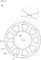
- FIG. 2 is a view showing a stator.
- the stator 200 may include a stator core 210, and the stator core 210 may include a coil 220 (shown in FIG. 1 ) wound therearound and forming a rotating magnetic field.
- the coil 220 wound around the stator core 210 may be surrounded and insulated by an insulating material. Meanwhile, the stator core 210 may be formed by combining a plurality of divided cores.
- the stator core 210 includes a plurality of teeth 230 extending inward. Although a total of 9 teeth 230 are shown in FIG. 2 , the motor according to one embodiment of the present invention is not limited thereto, and may be variously changed depending on the number of poles of the motor.
- a space between the adjacent teeth 230 corresponds to a slot space in which the coil is wound.
- End portions of the teeth 230 expand in a width direction and may be disposed toward a center C of the stator core 210.
- end surfaces 231 of the teeth 230 form a virtual perfect circle O with respect to the center C of the stator core 210 to reduce cogging torque.
- the rotor 300 is disposed to rotate with the stator 200.
- the rotor 300 may include a magnet attached to an inside of a rotor core or attached to an outer circumferential surface of the rotor core.
- the magnet attached to the rotor 300 causes an electromagnetic interaction with the stator 200 to rotate the rotor 300.
- a rotating shaft 400 may be coupled to a central portion of the rotor 300.
- the rotating shaft 400 may be supported by a bearing 500.
- the housing 100 of the motor 10 may include a teeth support part 110 (shown in FIG. 1 ).
- the teeth support part 110 comes in contact with end surfaces at lower portions of the teeth 230 of the stator 200 and supports the same to fix the stator 200.
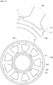
- FIG. 3 is a view showing a teeth support part.
- FIG. 3 clearly shows only a main portion to help conceptually and clearly understand the present invention. As a result, various modifications of a diagram are expected, and the scope of the present invention may not be limited by a particular shape shown in the drawing.
- the teeth support part 110 may protrude from a bottom surface of the housing 100.
- the stator 200 may be formed by combining a plurality of divided stator cores 210, and may be disposed in a misaligned form by not having a perfect circle O (shown in FIG. 2 ), formed by the end surfaces 231 of the teeth 230, due to assembly tolerance or vibration.
- the teeth support part 110 physically fixes the teeth 230 and induces the end surfaces of the teeth 230 formed on the stator core 210 to be aligned in a circumferential direction, and thus prevents the generation of cogging torque.
- the teeth support part 110 may protrude upward from a bottom surface of the housing 100 and may have an annular shape so that an outer face comes in contact with the end surfaces 231 of the teeth 230 of the stator core 210. Therefore, an outer diameter R1 (shown in FIG. 3 ) of the teeth support part 110 may be formed to correspond to an inner diameter R2 (shown in FIG. 2 ) of a virtual perfect circle O (shown in FIG. 2 ) formed by the plurality of teeth 230.
- the teeth support part 110 may be formed as an outer face of the bearing pocket part 600.
- the bearing pocket part 600 refers to an element protruding from a bottom surface of the housing 100 to form an accommodation space therein so that the bearing 500 is accommodated in the accommodation space.
- the accommodated bearing 500 rotatably supports the rotating shaft 400.
- the inner face of the bearing pocket part 600 is fixed to an outer ring of the accommodated bearing 500, and the outer face may be used as the teeth support part 110 supporting the end surfaces 231 of the teeth 230.
- FIG. 4 is a view showing a stator inserted into the teeth support part.
- the teeth support part 110 may include a guide 111.
- the guide 111 protrudes from an outer face of the teeth support part 110 and may be inserted into a gap between the end surfaces 231 of mutually adjacent teeth 230.
- the guide 111 may be formed long in an axial direction of the rotating shaft 400.
- Guides 111 may be formed at the outer face of the teeth support part 110 at regular intervals in a circumferential direction. In the circumferential direction, a space between mutually adjacent guides 111 may be formed to correspond to a width of an end portion of the teeth 230.
- the adjacent guides 111 and the outer face of the teeth support part 110 between the guides 111 form a slot into which an end portion of the teeth 230 is inserted, and fix positions of the teeth 230 so that the end surfaces 231 of the teeth 230 form a perfect circle O (shown in FIG. 2 ).
- the end surfaces of the teeth 230 may not be aligned due to an assembling process of the stator core 210 or external vibration, and the teeth support part 110 aligns and fixes the stator cores 210 so that an inner circumferential surface of the stator 200 has a perfect circle.
- a change in magnetic flux density between the magnet of the rotor 300 and the teeth 230 is minimized, and the generation of cogging torque can be prevented.
- the guide 111 may be easily formed by convexly protruding from an outer face of the bearing pocket part 600.
- FIG. 5 is a view showing a modified example of the teeth support part.
- the teeth support part 110 may be formed as a separate member protruding from a bottom surface of the housing 100 rather than as a part of the bearing pocket part 600, separately from the bearing pocket part 600.
- the teeth support part 110 may also have an annular shape to correspond to an inner circumferential area formed by the end surfaces of the teeth 230 of the stator 200.
Landscapes
- Engineering & Computer Science (AREA)
- Power Engineering (AREA)
- Iron Core Of Rotating Electric Machines (AREA)
- Permanent Magnet Type Synchronous Machine (AREA)
Abstract
Description
- The present invention relates to a motor housing and a motor including the same, and more specifically, to a motor housing including a stator having a plurality of teeth formed inward from a stator core, and a motor including the same.
- Cogging torque, which is non-uniform torque of a stator necessarily generated in a motor using a permanent magnet, refers to radial torque for moving to an equilibrium state, that is, a position at which magnetic energy of the motor is minimal.
- An abrupt change in magnetic flux around a boundary between N and S poles of a magnet generates the cogging torque. The cogging torque causes noise and vibration and reduces the performance of a motor, and thus it is important to reduce the cogging torque. Particularly, it is very important to reduce the cogging torque of a motor used for an actuator for controlling a precise position.
- Teeth of a stator and a magnet of a rotor are disposed to face each other, and cogging caused by a change in magnetic flux density may be generated in an edge area of the teeth of the stator. Particularly, when end surfaces of the teeth of the stators do not form a perfect circle, cogging torque may be generated.
- The present invention is directed to providing a motor housing which reduces cogging torque by inducing end surfaces of teeth of a stator to form a perfect circle, and a motor.
- Objects of the present invention are not limited to the above-described objects and other objects that have not been described should be clearly understood by those skilled in the art from the following description.
- One aspect of the present invention provides a housing comprising a teeth support part configured to protrude from an inner bottom surface and come in contact with end surfaces of teeth of a stator.
- The teeth support part may be configured to protrude in a cylindrical shape, and an outer diameter of the teeth support part is equal to an inner diameter of a virtual circle formed by end surfaces of the plurality of teeth.
- The teeth support part may include a guide protruding from an outer face thereof and is dispoesd between the teeth adjacent to each other.
- The housing may include a bearing pocket part configured to accommodate a bearing is disposed in side the teeth support part.
- An inner diameter of the teeth support part may be equal to an outer diameter of the bearing pocket portion.
- The teeth support part and the bearing pocket part may be integrally formed.
- Another aspect of the present invention provides a motor comprising a shaft, a rotor including a hole in which the shaft disposed, a stator disposed outside the rotor;and a housing accommodating the rotor and the shaft, wherein the stator including a plurality of teeth, wherein the housing including a teeth support part configured to protrude from an inner bottom surface and come in contact with end surfaces of the teeth of the stator to support the end surfaces of the teeth of the stator.
- The teeth support part may be configured to protrude in a cylindrical shape, and an outer diameter of the teeth support part is equal to an inner diameter of a virtual circle formed by end surfaces of the plurality of teeth.
- The teeth support part may include a guide protruding from an outer face thereof and is dispoesd between the teeth adjacent to each other.
- The guide may be formed at regular intervals on the outer surface of the teeth support part along the circumferential direction.
- A width of the guide in the circumferential direction may correspond to the length between the end surfaces of the adjacent teeth.
- According to an embodiment of the present invention, a motor housing and a motor including the same provide an advantageous effect of preventing the generation of cogging torque caused by the non-uniform assembly of a stator by a teeth support part formed to protrude from a bottom surface of the housing and coming in contact with end surfaces of teeth of the stator to support the same.
-
-
FIG. 1 is a view showing a motor according to one exemplary embodiment of the present invention. -
FIG. 2 is a view showing a stator. -
FIG. 3 is a view showing a teeth support part. -
FIG. 4 is a view showing a stator inserted into the teeth support part. -
FIG. 5 is a view showing a modified example of the teeth support part. - Hereinafter, exemplary embodiments of the present invention will be described in detail with reference to the accompanying drawings. Purposes, specific advantages, and novel features of the present invention will be clear from exemplary embodiments and the following detailed description in connection with the accompanying drawings. Terms and words used in this specification and claims should not be interpreted as limited to commonly used meanings or meanings in dictionaries and should be interpreted with meanings and concepts which are consistent with the technological scope of the present invention based on the principle that the inventors have appropriately defined concepts of terms in order to describe the present invention in the best way. When describing the present invention, detailed descriptions of related well-known technique that are deemed to unnecessarily obscure the gist of the present invention will be omitted.
- It should be understood that when an element is referred to as being "connected" or "coupled" to another element, the element may be directly connected or coupled to the other element or an intervening elements may be present. In contrast, when an element is referred to as being "directly connected" or "directly coupled" to another element, there are no intervening elements present.
-
FIG. 1 is a view showing a motor according to one exemplary embodiment of the present invention. - Referring to
FIG. 1 , amotor 10 according to the present invention may include ahousing 100, astator 200, arotor 300, and ashaft 400. - The
housing 100 has a cylindrical shape and has a space in which thestator 200 and therotor 300 may be mounted. In this case, the shape and the material of thehousing 100 may be variously changed, but a metal material, which is able to endure even a high temperature, may be selected because thehousing 100 is mounted in a vehicle. -
FIG. 2 is a view showing a stator. - Referring to
FIG. 2 , thestator 200 may include astator core 210, and thestator core 210 may include a coil 220 (shown inFIG. 1 ) wound therearound and forming a rotating magnetic field. Thecoil 220 wound around thestator core 210 may be surrounded and insulated by an insulating material. Meanwhile, thestator core 210 may be formed by combining a plurality of divided cores. - The
stator core 210 includes a plurality ofteeth 230 extending inward. Although a total of 9teeth 230 are shown inFIG. 2 , the motor according to one embodiment of the present invention is not limited thereto, and may be variously changed depending on the number of poles of the motor. - A space between the
adjacent teeth 230 corresponds to a slot space in which the coil is wound. - End portions of the
teeth 230 expand in a width direction and may be disposed toward a center C of thestator core 210. In this case,end surfaces 231 of theteeth 230 form a virtual perfect circle O with respect to the center C of thestator core 210 to reduce cogging torque. - Referring to
FIG. 1 , therotor 300 is disposed to rotate with thestator 200. Therotor 300 may include a magnet attached to an inside of a rotor core or attached to an outer circumferential surface of the rotor core. The magnet attached to therotor 300 causes an electromagnetic interaction with thestator 200 to rotate therotor 300. A rotatingshaft 400 may be coupled to a central portion of therotor 300. Thus, when therotor 300 rotates, the rotatingshaft 400 is also rotated. In this case, the rotatingshaft 400 may be supported by a bearing 500. - The
housing 100 of themotor 10 according to one exemplary embodiment of the present invention may include a teeth support part 110 (shown inFIG. 1 ). The teeth supportpart 110 comes in contact with end surfaces at lower portions of theteeth 230 of thestator 200 and supports the same to fix thestator 200. -
FIG. 3 is a view showing a teeth support part.FIG. 3 clearly shows only a main portion to help conceptually and clearly understand the present invention. As a result, various modifications of a diagram are expected, and the scope of the present invention may not be limited by a particular shape shown in the drawing. - Referring to
FIGS. 1 and3 , the teeth supportpart 110 may protrude from a bottom surface of thehousing 100. Thestator 200 may be formed by combining a plurality of dividedstator cores 210, and may be disposed in a misaligned form by not having a perfect circle O (shown inFIG. 2 ), formed by theend surfaces 231 of theteeth 230, due to assembly tolerance or vibration. - When the end surfaces 231 of the
teeth 230 are not aligned in a circumferential direction, a magnetic flux density is changed between the magnet of therotor 300 and theteeth 230 of thestator core 210 in the circumferential direction, and thus cogging torque may be generated. - In this case, the teeth support
part 110 physically fixes theteeth 230 and induces the end surfaces of theteeth 230 formed on thestator core 210 to be aligned in a circumferential direction, and thus prevents the generation of cogging torque. - The teeth support
part 110 may protrude upward from a bottom surface of thehousing 100 and may have an annular shape so that an outer face comes in contact with the end surfaces 231 of theteeth 230 of thestator core 210. Therefore, an outer diameter R1 (shown inFIG. 3 ) of the teeth supportpart 110 may be formed to correspond to an inner diameter R2 (shown inFIG. 2 ) of a virtual perfect circle O (shown inFIG. 2 ) formed by the plurality ofteeth 230. - As shown in
FIG. 1 , as one embodiment of the teeth supportpart 110, the teeth supportpart 110 may be formed as an outer face of thebearing pocket part 600. The bearingpocket part 600 refers to an element protruding from a bottom surface of thehousing 100 to form an accommodation space therein so that thebearing 500 is accommodated in the accommodation space. The accommodatedbearing 500 rotatably supports therotating shaft 400. - The inner face of the
bearing pocket part 600 is fixed to an outer ring of the accommodatedbearing 500, and the outer face may be used as the teeth supportpart 110 supporting the end surfaces 231 of theteeth 230. -
FIG. 4 is a view showing a stator inserted into the teeth support part. - Referring to
FIGS. 3 and4 , the teeth supportpart 110 may include aguide 111. - The
guide 111 protrudes from an outer face of the teeth supportpart 110 and may be inserted into a gap between the end surfaces 231 of mutuallyadjacent teeth 230. Theguide 111 may be formed long in an axial direction of therotating shaft 400.Guides 111 may be formed at the outer face of the teeth supportpart 110 at regular intervals in a circumferential direction. In the circumferential direction, a space between mutuallyadjacent guides 111 may be formed to correspond to a width of an end portion of theteeth 230. - That is, the
adjacent guides 111 and the outer face of the teeth supportpart 110 between theguides 111 form a slot into which an end portion of theteeth 230 is inserted, and fix positions of theteeth 230 so that the end surfaces 231 of theteeth 230 form a perfect circle O (shown inFIG. 2 ). - The end surfaces of the
teeth 230 may not be aligned due to an assembling process of thestator core 210 or external vibration, and the teeth supportpart 110 aligns and fixes thestator cores 210 so that an inner circumferential surface of thestator 200 has a perfect circle. Thus, a change in magnetic flux density between the magnet of therotor 300 and theteeth 230 is minimized, and the generation of cogging torque can be prevented. - When an outer face of the
bearing pocket part 600 is used as the teeth supportpart 110, theguide 111 may be easily formed by convexly protruding from an outer face of thebearing pocket part 600. -
FIG. 5 is a view showing a modified example of the teeth support part. - Referring to
FIG. 5 , as a modified example of the teeth supportpart 110, the teeth supportpart 110 may be formed as a separate member protruding from a bottom surface of thehousing 100 rather than as a part of thebearing pocket part 600, separately from the bearingpocket part 600. The teeth supportpart 110 may also have an annular shape to correspond to an inner circumferential area formed by the end surfaces of theteeth 230 of thestator 200. - The motor housing according to one exemplary embodiment of the present invention and the motor including the same have been described in detail with reference to the accompanying drawings.
- While the present invention has been particularly described with reference to exemplary embodiments, it should be understood by those of skilled in the art that various changes, modifications, and replacements in form and details may be made without departing from the spirit and scope of the present invention. Therefore, the exemplary embodiments and claims disclosed in the present invention should be considered in a descriptive sense only and not for purposes of limitation. Accordingly, the scope of the present invention is not limited by the embodiments and the accompanying drawings. The scope of the present invention should be defined by the appended claims, and encompasses all modifications and equivalents that fall within the scope of the appended claims.
-
- 10: MOTOR
- 100: HOUSING
- 200: STATOR
- 210: STATOR CORE
- 220: COIL
- 230: TEETH
- 231: END SURFACES
- 300: ROTOR
- 400: ROTATING SHAFT
- 500: BEARING
- 600: BEARING POCKET PART
Claims (11)
- A housing including a teeth support part configured to protrude from an inner bottom surface and come in contact with end surfaces of teeth of a stator.
- The housing of claim 1, wherein the teeth support part is configured to protrude in a cylindrical shape, and an outer diameter of the teeth support part is equal to an inner diameter of a virtual circle formed by end surfaces of the plurality of teeth.
- The housing of claim 1, wherein the teeth support part includes a guide protruding from an outer face thereof and is disposed between the teeth adjacent to each other.
- The housing of claim 3, wherein the housing includes a bearing pocket part configured to accommodate a bearing is disposed in side the teeth support part.
- The housing of claim 4, an inner diameter of the teeth support part is equal to an outer diameter of the bearing pocket portion.
- wherein the teeth support part and the bearing pocket part are integrally formed.
- A motor comprising;
a shaft;
a rotor including a hole in which the shaft disposed;
a stator disposed outside the rotor; and
a housing accommodating the rotor and the shaft;
wherein the stator including a plurality of teeth;
wherein the housing including a teeth support part configured to protrude from an inner bottom surface and come in contact with end surfaces of the teeth of the stator to support the end surfaces of the teeth of the stator. - The motor of claim 7, wherein the teeth support part is configured to protrude in a cylindrical shape, and an outer diameter of the teeth support part is equal to an inner diameter of a virtual circle formed by end surfaces of the plurality of teeth.
- The motor of claim 7, wherein the teeth support part includes a guide protruding from an outer face thereof and is disposed between the teeth adjacent to each other.
- The motor of claim 9, wherein the guide is formed at regular intervals on the outer surface of the teeth support part along the circumferential direction.
- The motor of claim 9, a width of the guide in the circumferential direction corresponding to the length between the end surfaces of the adjacent teeth.
Applications Claiming Priority (2)
| Application Number | Priority Date | Filing Date | Title |
|---|---|---|---|
| KR1020150109564A KR102452161B1 (en) | 2015-08-03 | 2015-08-03 | Motor |
| PCT/KR2016/008435 WO2017023061A1 (en) | 2015-08-03 | 2016-08-01 | Housing and motor including same |
Publications (3)
| Publication Number | Publication Date |
|---|---|
| EP3334013A1 true EP3334013A1 (en) | 2018-06-13 |
| EP3334013A4 EP3334013A4 (en) | 2019-02-27 |
| EP3334013B1 EP3334013B1 (en) | 2021-04-07 |
Family
ID=57943306
Family Applications (1)
| Application Number | Title | Priority Date | Filing Date |
|---|---|---|---|
| EP16833297.1A Active EP3334013B1 (en) | 2015-08-03 | 2016-08-01 | Housing and motor including same |
Country Status (5)
| Country | Link |
|---|---|
| US (2) | US10651703B2 (en) |
| EP (1) | EP3334013B1 (en) |
| KR (1) | KR102452161B1 (en) |
| CN (2) | CN107925302B (en) |
| WO (1) | WO2017023061A1 (en) |
Families Citing this family (3)
| Publication number | Priority date | Publication date | Assignee | Title |
|---|---|---|---|---|
| KR102452161B1 (en) * | 2015-08-03 | 2022-10-11 | 엘지이노텍 주식회사 | Motor |
| KR102715292B1 (en) * | 2018-11-28 | 2024-10-11 | 엘지이노텍 주식회사 | Motor |
| US12294278B2 (en) * | 2020-03-18 | 2025-05-06 | Lg Innotek Co., Ltd. | Motor |
Family Cites Families (20)
| Publication number | Priority date | Publication date | Assignee | Title |
|---|---|---|---|---|
| DE2101672A1 (en) * | 1971-01-15 | 1972-07-20 | Licentia Gmbh | Heating water circulation pump |
| JPS6091852A (en) | 1983-10-20 | 1985-05-23 | Ricoh Elemex Corp | Rotary motor |
| JPS60167639A (en) * | 1984-02-10 | 1985-08-31 | Hitachi Ltd | Magnetic crown for rotating electrical machines |
| JPS6455024A (en) * | 1987-08-25 | 1989-03-02 | Olympus Optical Co | Motor |
| US5698917A (en) * | 1995-09-25 | 1997-12-16 | Glacier Rpb Inc. | Electromagnetic bearing with a stationary armature canning arrangement |
| JPH1118332A (en) * | 1997-06-20 | 1999-01-22 | Matsushita Electric Ind Co Ltd | Stator and manufacturing method thereof |
| JP2990432B1 (en) * | 1998-05-12 | 1999-12-13 | ミネベア株式会社 | Stepping motor |
| DE10226976A1 (en) * | 2002-06-17 | 2004-03-25 | Siemens Ag | Electric motor with a multi-pole rotor and a multi-pole stator |
| JP2005210838A (en) * | 2004-01-23 | 2005-08-04 | Meidensha Corp | Rotating electric machine |
| JP2006121870A (en) | 2004-10-25 | 2006-05-11 | Sanyo Electric Co Ltd | Motor device |
| CN1780091A (en) * | 2004-11-19 | 2006-05-31 | 乐金电子(天津)电器有限公司 | Stator of electric motor with insulator |
| KR20070040913A (en) * | 2005-10-13 | 2007-04-18 | 엘지이노텍 주식회사 | Stator for motor |
| DE102006038909A1 (en) * | 2006-08-18 | 2008-02-21 | Vorwerk & Co. Interholding Gmbh | Electric motor with runner |
| JP2008236973A (en) | 2007-03-23 | 2008-10-02 | Matsushita Electric Ind Co Ltd | Electric motor for hermetic compressor |
| JP2012019569A (en) * | 2010-07-06 | 2012-01-26 | Mitsubishi Electric Corp | Electric motor and electric blower using the same |
| CN202218137U (en) * | 2011-08-10 | 2012-05-09 | 徐州工业职业技术学院 | Closed slot permanent magnet synchronous motor with strengthened structure |
| CN103036328A (en) * | 2011-09-29 | 2013-04-10 | 华锐风电科技(集团)股份有限公司 | Stator, manufacture method and motor |
| KR101251261B1 (en) * | 2011-11-16 | 2013-04-10 | 현대자동차주식회사 | Canned motor for reducing cogging torque |
| DE102013109522B4 (en) * | 2013-09-02 | 2015-06-18 | Rausch & Pausch Gmbh | Canned motor with high-pressure-resistant split tube |
| KR102452161B1 (en) * | 2015-08-03 | 2022-10-11 | 엘지이노텍 주식회사 | Motor |
-
2015
- 2015-08-03 KR KR1020150109564A patent/KR102452161B1/en active Active
-
2016
- 2016-08-01 CN CN201680046029.0A patent/CN107925302B/en active Active
- 2016-08-01 CN CN202010156711.3A patent/CN111431318B/en active Active
- 2016-08-01 WO PCT/KR2016/008435 patent/WO2017023061A1/en not_active Ceased
- 2016-08-01 US US15/750,454 patent/US10651703B2/en active Active
- 2016-08-01 EP EP16833297.1A patent/EP3334013B1/en active Active
-
2020
- 2020-03-09 US US16/813,153 patent/US10892661B2/en active Active
Also Published As
| Publication number | Publication date |
|---|---|
| KR20170016150A (en) | 2017-02-13 |
| US10651703B2 (en) | 2020-05-12 |
| EP3334013A4 (en) | 2019-02-27 |
| WO2017023061A1 (en) | 2017-02-09 |
| US10892661B2 (en) | 2021-01-12 |
| KR102452161B1 (en) | 2022-10-11 |
| CN111431318A (en) | 2020-07-17 |
| CN107925302B (en) | 2020-04-03 |
| US20200212751A1 (en) | 2020-07-02 |
| CN111431318B (en) | 2023-04-11 |
| US20180226847A1 (en) | 2018-08-09 |
| CN107925302A (en) | 2018-04-17 |
| EP3334013B1 (en) | 2021-04-07 |
Similar Documents
| Publication | Publication Date | Title |
|---|---|---|
| US10892661B2 (en) | Motor | |
| JP7014763B2 (en) | Lead screw device | |
| KR20170062889A (en) | Surface permanent magnet synchronous motor | |
| US20130285483A1 (en) | Axial flux permanent magnet motor | |
| US20140091667A1 (en) | Armature and motor | |
| KR102554396B1 (en) | Rotor and Motor having the same | |
| KR102458635B1 (en) | Rotor and Motor having the samm | |
| JP6616367B2 (en) | motor | |
| JP6326662B2 (en) | Permanent magnet type rotating electrical machine and magnet fixing method thereof | |
| JPWO2018180636A1 (en) | motor | |
| JP2021057992A (en) | Rotor and motor | |
| KR101855834B1 (en) | Electric motor | |
| JP6162567B2 (en) | Inner rotor type motor | |
| JP2019062688A (en) | motor | |
| EP3364527A1 (en) | Electric motor and blower | |
| KR101892136B1 (en) | The rotor of the axial magnetic flux motor and axial magnetic flux motor having same | |
| JP2021136758A (en) | Brush holder and motor | |
| JP2009136056A (en) | Electric motor | |
| JP5252789B2 (en) | Axial gap motor | |
| JP2013128409A (en) | Rotary electric machine | |
| JP2016072994A (en) | Rotating electric machine | |
| JP2020114113A (en) | Rotating electric machine | |
| JP6040014B2 (en) | motor | |
| JP7313239B2 (en) | Stator of inner rotor type motor | |
| KR102565241B1 (en) | Motor |
Legal Events
| Date | Code | Title | Description |
|---|---|---|---|
| STAA | Information on the status of an ep patent application or granted ep patent |
Free format text: STATUS: THE INTERNATIONAL PUBLICATION HAS BEEN MADE |
|
| PUAI | Public reference made under article 153(3) epc to a published international application that has entered the european phase |
Free format text: ORIGINAL CODE: 0009012 |
|
| STAA | Information on the status of an ep patent application or granted ep patent |
Free format text: STATUS: REQUEST FOR EXAMINATION WAS MADE |
|
| 17P | Request for examination filed |
Effective date: 20180209 |
|
| AK | Designated contracting states |
Kind code of ref document: A1 Designated state(s): AL AT BE BG CH CY CZ DE DK EE ES FI FR GB GR HR HU IE IS IT LI LT LU LV MC MK MT NL NO PL PT RO RS SE SI SK SM TR |
|
| AX | Request for extension of the european patent |
Extension state: BA ME |
|
| DAV | Request for validation of the european patent (deleted) | ||
| DAX | Request for extension of the european patent (deleted) | ||
| A4 | Supplementary search report drawn up and despatched |
Effective date: 20190130 |
|
| RIC1 | Information provided on ipc code assigned before grant |
Ipc: H02K 5/04 20060101AFI20190124BHEP Ipc: H02K 1/18 20060101ALI20190124BHEP Ipc: H02K 5/16 20060101ALI20190124BHEP |
|
| STAA | Information on the status of an ep patent application or granted ep patent |
Free format text: STATUS: EXAMINATION IS IN PROGRESS |
|
| 17Q | First examination report despatched |
Effective date: 20200131 |
|
| GRAP | Despatch of communication of intention to grant a patent |
Free format text: ORIGINAL CODE: EPIDOSNIGR1 |
|
| STAA | Information on the status of an ep patent application or granted ep patent |
Free format text: STATUS: GRANT OF PATENT IS INTENDED |
|
| INTG | Intention to grant announced |
Effective date: 20201103 |
|
| GRAS | Grant fee paid |
Free format text: ORIGINAL CODE: EPIDOSNIGR3 |
|
| GRAA | (expected) grant |
Free format text: ORIGINAL CODE: 0009210 |
|
| STAA | Information on the status of an ep patent application or granted ep patent |
Free format text: STATUS: THE PATENT HAS BEEN GRANTED |
|
| AK | Designated contracting states |
Kind code of ref document: B1 Designated state(s): AL AT BE BG CH CY CZ DE DK EE ES FI FR GB GR HR HU IE IS IT LI LT LU LV MC MK MT NL NO PL PT RO RS SE SI SK SM TR |
|
| REG | Reference to a national code |
Ref country code: GB Ref legal event code: FG4D |
|
| REG | Reference to a national code |
Ref country code: AT Ref legal event code: REF Ref document number: 1380959 Country of ref document: AT Kind code of ref document: T Effective date: 20210415 Ref country code: CH Ref legal event code: EP |
|
| REG | Reference to a national code |
Ref country code: DE Ref legal event code: R096 Ref document number: 602016055796 Country of ref document: DE |
|
| REG | Reference to a national code |
Ref country code: IE Ref legal event code: FG4D |
|
| REG | Reference to a national code |
Ref country code: NL Ref legal event code: FP |
|
| REG | Reference to a national code |
Ref country code: LT Ref legal event code: MG9D |
|
| REG | Reference to a national code |
Ref country code: AT Ref legal event code: MK05 Ref document number: 1380959 Country of ref document: AT Kind code of ref document: T Effective date: 20210407 |
|
| PG25 | Lapsed in a contracting state [announced via postgrant information from national office to epo] |
Ref country code: HR Free format text: LAPSE BECAUSE OF FAILURE TO SUBMIT A TRANSLATION OF THE DESCRIPTION OR TO PAY THE FEE WITHIN THE PRESCRIBED TIME-LIMIT Effective date: 20210407 Ref country code: BG Free format text: LAPSE BECAUSE OF FAILURE TO SUBMIT A TRANSLATION OF THE DESCRIPTION OR TO PAY THE FEE WITHIN THE PRESCRIBED TIME-LIMIT Effective date: 20210707 Ref country code: AT Free format text: LAPSE BECAUSE OF FAILURE TO SUBMIT A TRANSLATION OF THE DESCRIPTION OR TO PAY THE FEE WITHIN THE PRESCRIBED TIME-LIMIT Effective date: 20210407 Ref country code: FI Free format text: LAPSE BECAUSE OF FAILURE TO SUBMIT A TRANSLATION OF THE DESCRIPTION OR TO PAY THE FEE WITHIN THE PRESCRIBED TIME-LIMIT Effective date: 20210407 Ref country code: LT Free format text: LAPSE BECAUSE OF FAILURE TO SUBMIT A TRANSLATION OF THE DESCRIPTION OR TO PAY THE FEE WITHIN THE PRESCRIBED TIME-LIMIT Effective date: 20210407 |
|
| PG25 | Lapsed in a contracting state [announced via postgrant information from national office to epo] |
Ref country code: NO Free format text: LAPSE BECAUSE OF FAILURE TO SUBMIT A TRANSLATION OF THE DESCRIPTION OR TO PAY THE FEE WITHIN THE PRESCRIBED TIME-LIMIT Effective date: 20210707 Ref country code: PT Free format text: LAPSE BECAUSE OF FAILURE TO SUBMIT A TRANSLATION OF THE DESCRIPTION OR TO PAY THE FEE WITHIN THE PRESCRIBED TIME-LIMIT Effective date: 20210809 Ref country code: PL Free format text: LAPSE BECAUSE OF FAILURE TO SUBMIT A TRANSLATION OF THE DESCRIPTION OR TO PAY THE FEE WITHIN THE PRESCRIBED TIME-LIMIT Effective date: 20210407 Ref country code: RS Free format text: LAPSE BECAUSE OF FAILURE TO SUBMIT A TRANSLATION OF THE DESCRIPTION OR TO PAY THE FEE WITHIN THE PRESCRIBED TIME-LIMIT Effective date: 20210407 Ref country code: SE Free format text: LAPSE BECAUSE OF FAILURE TO SUBMIT A TRANSLATION OF THE DESCRIPTION OR TO PAY THE FEE WITHIN THE PRESCRIBED TIME-LIMIT Effective date: 20210407 Ref country code: GR Free format text: LAPSE BECAUSE OF FAILURE TO SUBMIT A TRANSLATION OF THE DESCRIPTION OR TO PAY THE FEE WITHIN THE PRESCRIBED TIME-LIMIT Effective date: 20210708 Ref country code: IS Free format text: LAPSE BECAUSE OF FAILURE TO SUBMIT A TRANSLATION OF THE DESCRIPTION OR TO PAY THE FEE WITHIN THE PRESCRIBED TIME-LIMIT Effective date: 20210807 Ref country code: LV Free format text: LAPSE BECAUSE OF FAILURE TO SUBMIT A TRANSLATION OF THE DESCRIPTION OR TO PAY THE FEE WITHIN THE PRESCRIBED TIME-LIMIT Effective date: 20210407 |
|
| REG | Reference to a national code |
Ref country code: DE Ref legal event code: R097 Ref document number: 602016055796 Country of ref document: DE |
|
| PG25 | Lapsed in a contracting state [announced via postgrant information from national office to epo] |
Ref country code: EE Free format text: LAPSE BECAUSE OF FAILURE TO SUBMIT A TRANSLATION OF THE DESCRIPTION OR TO PAY THE FEE WITHIN THE PRESCRIBED TIME-LIMIT Effective date: 20210407 Ref country code: CZ Free format text: LAPSE BECAUSE OF FAILURE TO SUBMIT A TRANSLATION OF THE DESCRIPTION OR TO PAY THE FEE WITHIN THE PRESCRIBED TIME-LIMIT Effective date: 20210407 Ref country code: DK Free format text: LAPSE BECAUSE OF FAILURE TO SUBMIT A TRANSLATION OF THE DESCRIPTION OR TO PAY THE FEE WITHIN THE PRESCRIBED TIME-LIMIT Effective date: 20210407 Ref country code: ES Free format text: LAPSE BECAUSE OF FAILURE TO SUBMIT A TRANSLATION OF THE DESCRIPTION OR TO PAY THE FEE WITHIN THE PRESCRIBED TIME-LIMIT Effective date: 20210407 Ref country code: RO Free format text: LAPSE BECAUSE OF FAILURE TO SUBMIT A TRANSLATION OF THE DESCRIPTION OR TO PAY THE FEE WITHIN THE PRESCRIBED TIME-LIMIT Effective date: 20210407 Ref country code: SK Free format text: LAPSE BECAUSE OF FAILURE TO SUBMIT A TRANSLATION OF THE DESCRIPTION OR TO PAY THE FEE WITHIN THE PRESCRIBED TIME-LIMIT Effective date: 20210407 Ref country code: SM Free format text: LAPSE BECAUSE OF FAILURE TO SUBMIT A TRANSLATION OF THE DESCRIPTION OR TO PAY THE FEE WITHIN THE PRESCRIBED TIME-LIMIT Effective date: 20210407 |
|
| PLBE | No opposition filed within time limit |
Free format text: ORIGINAL CODE: 0009261 |
|
| STAA | Information on the status of an ep patent application or granted ep patent |
Free format text: STATUS: NO OPPOSITION FILED WITHIN TIME LIMIT |
|
| 26N | No opposition filed |
Effective date: 20220110 |
|
| REG | Reference to a national code |
Ref country code: CH Ref legal event code: PL |
|
| PG25 | Lapsed in a contracting state [announced via postgrant information from national office to epo] |
Ref country code: MC Free format text: LAPSE BECAUSE OF FAILURE TO SUBMIT A TRANSLATION OF THE DESCRIPTION OR TO PAY THE FEE WITHIN THE PRESCRIBED TIME-LIMIT Effective date: 20210407 |
|
| REG | Reference to a national code |
Ref country code: BE Ref legal event code: MM Effective date: 20210831 |
|
| GBPC | Gb: european patent ceased through non-payment of renewal fee |
Effective date: 20210801 |
|
| PG25 | Lapsed in a contracting state [announced via postgrant information from national office to epo] |
Ref country code: LI Free format text: LAPSE BECAUSE OF NON-PAYMENT OF DUE FEES Effective date: 20210831 Ref country code: CH Free format text: LAPSE BECAUSE OF NON-PAYMENT OF DUE FEES Effective date: 20210831 |
|
| PG25 | Lapsed in a contracting state [announced via postgrant information from national office to epo] |
Ref country code: IS Free format text: LAPSE BECAUSE OF FAILURE TO SUBMIT A TRANSLATION OF THE DESCRIPTION OR TO PAY THE FEE WITHIN THE PRESCRIBED TIME-LIMIT Effective date: 20210807 Ref country code: LU Free format text: LAPSE BECAUSE OF NON-PAYMENT OF DUE FEES Effective date: 20210801 Ref country code: AL Free format text: LAPSE BECAUSE OF FAILURE TO SUBMIT A TRANSLATION OF THE DESCRIPTION OR TO PAY THE FEE WITHIN THE PRESCRIBED TIME-LIMIT Effective date: 20210407 |
|
| PG25 | Lapsed in a contracting state [announced via postgrant information from national office to epo] |
Ref country code: IT Free format text: LAPSE BECAUSE OF FAILURE TO SUBMIT A TRANSLATION OF THE DESCRIPTION OR TO PAY THE FEE WITHIN THE PRESCRIBED TIME-LIMIT Effective date: 20210407 Ref country code: IE Free format text: LAPSE BECAUSE OF NON-PAYMENT OF DUE FEES Effective date: 20210801 Ref country code: GB Free format text: LAPSE BECAUSE OF NON-PAYMENT OF DUE FEES Effective date: 20210801 Ref country code: BE Free format text: LAPSE BECAUSE OF NON-PAYMENT OF DUE FEES Effective date: 20210831 |
|
| PG25 | Lapsed in a contracting state [announced via postgrant information from national office to epo] |
Ref country code: HU Free format text: LAPSE BECAUSE OF FAILURE TO SUBMIT A TRANSLATION OF THE DESCRIPTION OR TO PAY THE FEE WITHIN THE PRESCRIBED TIME-LIMIT; INVALID AB INITIO Effective date: 20160801 |
|
| PG25 | Lapsed in a contracting state [announced via postgrant information from national office to epo] |
Ref country code: CY Free format text: LAPSE BECAUSE OF FAILURE TO SUBMIT A TRANSLATION OF THE DESCRIPTION OR TO PAY THE FEE WITHIN THE PRESCRIBED TIME-LIMIT Effective date: 20210407 |
|
| PG25 | Lapsed in a contracting state [announced via postgrant information from national office to epo] |
Ref country code: MK Free format text: LAPSE BECAUSE OF FAILURE TO SUBMIT A TRANSLATION OF THE DESCRIPTION OR TO PAY THE FEE WITHIN THE PRESCRIBED TIME-LIMIT Effective date: 20210407 |
|
| PG25 | Lapsed in a contracting state [announced via postgrant information from national office to epo] |
Ref country code: TR Free format text: LAPSE BECAUSE OF FAILURE TO SUBMIT A TRANSLATION OF THE DESCRIPTION OR TO PAY THE FEE WITHIN THE PRESCRIBED TIME-LIMIT Effective date: 20210407 |
|
| PGFP | Annual fee paid to national office [announced via postgrant information from national office to epo] |
Ref country code: NL Payment date: 20240722 Year of fee payment: 9 |
|
| PG25 | Lapsed in a contracting state [announced via postgrant information from national office to epo] |
Ref country code: MT Free format text: LAPSE BECAUSE OF FAILURE TO SUBMIT A TRANSLATION OF THE DESCRIPTION OR TO PAY THE FEE WITHIN THE PRESCRIBED TIME-LIMIT Effective date: 20210407 |
|
| PGFP | Annual fee paid to national office [announced via postgrant information from national office to epo] |
Ref country code: DE Payment date: 20240722 Year of fee payment: 9 |
|
| PGFP | Annual fee paid to national office [announced via postgrant information from national office to epo] |
Ref country code: FR Payment date: 20240723 Year of fee payment: 9 |
|
| REG | Reference to a national code |
Ref country code: DE Ref legal event code: R119 Ref document number: 602016055796 Country of ref document: DE |
|
| REG | Reference to a national code |
Ref country code: NL Ref legal event code: MM Effective date: 20250901 |