EP3333957A1 - Lithium-ion secondary cell - Google Patents
Lithium-ion secondary cell Download PDFInfo
- Publication number
- EP3333957A1 EP3333957A1 EP16832733.6A EP16832733A EP3333957A1 EP 3333957 A1 EP3333957 A1 EP 3333957A1 EP 16832733 A EP16832733 A EP 16832733A EP 3333957 A1 EP3333957 A1 EP 3333957A1
- Authority
- EP
- European Patent Office
- Prior art keywords
- anode
- cathode
- lithium
- battery
- active material
- Prior art date
- Legal status (The legal status is an assumption and is not a legal conclusion. Google has not performed a legal analysis and makes no representation as to the accuracy of the status listed.)
- Withdrawn
Links
Images
Classifications
-
- H—ELECTRICITY
- H01—ELECTRIC ELEMENTS
- H01M—PROCESSES OR MEANS, e.g. BATTERIES, FOR THE DIRECT CONVERSION OF CHEMICAL ENERGY INTO ELECTRICAL ENERGY
- H01M10/00—Secondary cells; Manufacture thereof
- H01M10/05—Accumulators with non-aqueous electrolyte
- H01M10/052—Li-accumulators
- H01M10/0525—Rocking-chair batteries, i.e. batteries with lithium insertion or intercalation in both electrodes; Lithium-ion batteries
-
- H—ELECTRICITY
- H01—ELECTRIC ELEMENTS
- H01M—PROCESSES OR MEANS, e.g. BATTERIES, FOR THE DIRECT CONVERSION OF CHEMICAL ENERGY INTO ELECTRICAL ENERGY
- H01M10/00—Secondary cells; Manufacture thereof
- H01M10/05—Accumulators with non-aqueous electrolyte
- H01M10/056—Accumulators with non-aqueous electrolyte characterised by the materials used as electrolytes, e.g. mixed inorganic/organic electrolytes
- H01M10/0564—Accumulators with non-aqueous electrolyte characterised by the materials used as electrolytes, e.g. mixed inorganic/organic electrolytes the electrolyte being constituted of organic materials only
- H01M10/0566—Liquid materials
- H01M10/0567—Liquid materials characterised by the additives
-
- H—ELECTRICITY
- H01—ELECTRIC ELEMENTS
- H01M—PROCESSES OR MEANS, e.g. BATTERIES, FOR THE DIRECT CONVERSION OF CHEMICAL ENERGY INTO ELECTRICAL ENERGY
- H01M10/00—Secondary cells; Manufacture thereof
- H01M10/42—Methods or arrangements for servicing or maintenance of secondary cells or secondary half-cells
- H01M10/48—Accumulators combined with arrangements for measuring, testing or indicating the condition of cells, e.g. the level or density of the electrolyte
- H01M10/486—Accumulators combined with arrangements for measuring, testing or indicating the condition of cells, e.g. the level or density of the electrolyte for measuring temperature
-
- H—ELECTRICITY
- H01—ELECTRIC ELEMENTS
- H01M—PROCESSES OR MEANS, e.g. BATTERIES, FOR THE DIRECT CONVERSION OF CHEMICAL ENERGY INTO ELECTRICAL ENERGY
- H01M4/00—Electrodes
- H01M4/02—Electrodes composed of, or comprising, active material
- H01M4/13—Electrodes for accumulators with non-aqueous electrolyte, e.g. for lithium-accumulators; Processes of manufacture thereof
- H01M4/131—Electrodes based on mixed oxides or hydroxides, or on mixtures of oxides or hydroxides, e.g. LiCoOx
-
- H—ELECTRICITY
- H01—ELECTRIC ELEMENTS
- H01M—PROCESSES OR MEANS, e.g. BATTERIES, FOR THE DIRECT CONVERSION OF CHEMICAL ENERGY INTO ELECTRICAL ENERGY
- H01M4/00—Electrodes
- H01M4/02—Electrodes composed of, or comprising, active material
- H01M4/13—Electrodes for accumulators with non-aqueous electrolyte, e.g. for lithium-accumulators; Processes of manufacture thereof
- H01M4/133—Electrodes based on carbonaceous material, e.g. graphite-intercalation compounds or CFx
-
- H—ELECTRICITY
- H01—ELECTRIC ELEMENTS
- H01M—PROCESSES OR MEANS, e.g. BATTERIES, FOR THE DIRECT CONVERSION OF CHEMICAL ENERGY INTO ELECTRICAL ENERGY
- H01M4/00—Electrodes
- H01M4/02—Electrodes composed of, or comprising, active material
- H01M4/36—Selection of substances as active materials, active masses, active liquids
- H01M4/48—Selection of substances as active materials, active masses, active liquids of inorganic oxides or hydroxides
- H01M4/50—Selection of substances as active materials, active masses, active liquids of inorganic oxides or hydroxides of manganese
- H01M4/505—Selection of substances as active materials, active masses, active liquids of inorganic oxides or hydroxides of manganese of mixed oxides or hydroxides containing manganese for inserting or intercalating light metals, e.g. LiMn2O4 or LiMn2OxFy
-
- H—ELECTRICITY
- H01—ELECTRIC ELEMENTS
- H01M—PROCESSES OR MEANS, e.g. BATTERIES, FOR THE DIRECT CONVERSION OF CHEMICAL ENERGY INTO ELECTRICAL ENERGY
- H01M4/00—Electrodes
- H01M4/02—Electrodes composed of, or comprising, active material
- H01M4/36—Selection of substances as active materials, active masses, active liquids
- H01M4/48—Selection of substances as active materials, active masses, active liquids of inorganic oxides or hydroxides
- H01M4/52—Selection of substances as active materials, active masses, active liquids of inorganic oxides or hydroxides of nickel, cobalt or iron
- H01M4/525—Selection of substances as active materials, active masses, active liquids of inorganic oxides or hydroxides of nickel, cobalt or iron of mixed oxides or hydroxides containing iron, cobalt or nickel for inserting or intercalating light metals, e.g. LiNiO2, LiCoO2 or LiCoOxFy
-
- H—ELECTRICITY
- H01—ELECTRIC ELEMENTS
- H01M—PROCESSES OR MEANS, e.g. BATTERIES, FOR THE DIRECT CONVERSION OF CHEMICAL ENERGY INTO ELECTRICAL ENERGY
- H01M4/00—Electrodes
- H01M4/02—Electrodes composed of, or comprising, active material
- H01M4/64—Carriers or collectors
- H01M4/66—Selection of materials
- H01M4/661—Metal or alloys, e.g. alloy coatings
-
- H—ELECTRICITY
- H01—ELECTRIC ELEMENTS
- H01M—PROCESSES OR MEANS, e.g. BATTERIES, FOR THE DIRECT CONVERSION OF CHEMICAL ENERGY INTO ELECTRICAL ENERGY
- H01M50/00—Constructional details or processes of manufacture of the non-active parts of electrochemical cells other than fuel cells, e.g. hybrid cells
- H01M50/40—Separators; Membranes; Diaphragms; Spacing elements inside cells
- H01M50/409—Separators, membranes or diaphragms characterised by the material
- H01M50/411—Organic material
- H01M50/414—Synthetic resins, e.g. thermoplastics or thermosetting resins
- H01M50/417—Polyolefins
-
- H—ELECTRICITY
- H01—ELECTRIC ELEMENTS
- H01M—PROCESSES OR MEANS, e.g. BATTERIES, FOR THE DIRECT CONVERSION OF CHEMICAL ENERGY INTO ELECTRICAL ENERGY
- H01M50/00—Constructional details or processes of manufacture of the non-active parts of electrochemical cells other than fuel cells, e.g. hybrid cells
- H01M50/40—Separators; Membranes; Diaphragms; Spacing elements inside cells
- H01M50/409—Separators, membranes or diaphragms characterised by the material
- H01M50/443—Particulate material
-
- H—ELECTRICITY
- H01—ELECTRIC ELEMENTS
- H01M—PROCESSES OR MEANS, e.g. BATTERIES, FOR THE DIRECT CONVERSION OF CHEMICAL ENERGY INTO ELECTRICAL ENERGY
- H01M50/00—Constructional details or processes of manufacture of the non-active parts of electrochemical cells other than fuel cells, e.g. hybrid cells
- H01M50/40—Separators; Membranes; Diaphragms; Spacing elements inside cells
- H01M50/489—Separators, membranes, diaphragms or spacing elements inside the cells, characterised by their physical properties, e.g. swelling degree, hydrophilicity or shut down properties
-
- H—ELECTRICITY
- H01—ELECTRIC ELEMENTS
- H01M—PROCESSES OR MEANS, e.g. BATTERIES, FOR THE DIRECT CONVERSION OF CHEMICAL ENERGY INTO ELECTRICAL ENERGY
- H01M4/00—Electrodes
- H01M4/02—Electrodes composed of, or comprising, active material
- H01M2004/026—Electrodes composed of, or comprising, active material characterised by the polarity
- H01M2004/027—Negative electrodes
-
- H—ELECTRICITY
- H01—ELECTRIC ELEMENTS
- H01M—PROCESSES OR MEANS, e.g. BATTERIES, FOR THE DIRECT CONVERSION OF CHEMICAL ENERGY INTO ELECTRICAL ENERGY
- H01M4/00—Electrodes
- H01M4/02—Electrodes composed of, or comprising, active material
- H01M2004/026—Electrodes composed of, or comprising, active material characterised by the polarity
- H01M2004/028—Positive electrodes
-
- H—ELECTRICITY
- H01—ELECTRIC ELEMENTS
- H01M—PROCESSES OR MEANS, e.g. BATTERIES, FOR THE DIRECT CONVERSION OF CHEMICAL ENERGY INTO ELECTRICAL ENERGY
- H01M10/00—Secondary cells; Manufacture thereof
- H01M10/42—Methods or arrangements for servicing or maintenance of secondary cells or secondary half-cells
- H01M2010/4292—Aspects relating to capacity ratio of electrodes/electrolyte or anode/cathode
-
- Y—GENERAL TAGGING OF NEW TECHNOLOGICAL DEVELOPMENTS; GENERAL TAGGING OF CROSS-SECTIONAL TECHNOLOGIES SPANNING OVER SEVERAL SECTIONS OF THE IPC; TECHNICAL SUBJECTS COVERED BY FORMER USPC CROSS-REFERENCE ART COLLECTIONS [XRACs] AND DIGESTS
- Y02—TECHNOLOGIES OR APPLICATIONS FOR MITIGATION OR ADAPTATION AGAINST CLIMATE CHANGE
- Y02E—REDUCTION OF GREENHOUSE GAS [GHG] EMISSIONS, RELATED TO ENERGY GENERATION, TRANSMISSION OR DISTRIBUTION
- Y02E60/00—Enabling technologies; Technologies with a potential or indirect contribution to GHG emissions mitigation
- Y02E60/10—Energy storage using batteries
Definitions
- the present invention relates to a nonaqueous-electrolyte battery, and more particularly, to a lithium-ion secondary battery.
- Nonaqueous-electrolyte batteries are used for automobiles including hybrid vehicles and electric vehicles.
- Lithium-ion secondary batteries are commonly used as such on-vehicle batteries. As lithium-ion secondary batteries have larger capacity through development efforts, their safety needs to be ensured.
- a lithium-ion secondary battery charged after fully charged can typically be in an overcharge state, which is unstable.
- a lithium-ion secondary battery using, as its cathode material, a lithium composite oxide with a layered crystal structure having a high energy density can have an overcharge state, in which lithium ions continuously move from the cathode (positive electrode) to the anode (negative electrode).
- the limited capacity of the anode for lithium ions (or anode capacity) can then cause overflow of lithium ions from the anode.
- One method for preventing such overcharge includes monitoring the voltage of a lithium-ion secondary battery to prevent an overcharge. Another method includes adding a particular additive to an electrolyte for electrochemical overcharge protection.
- Japanese Unexamined Patent Application Publication No. 2013-178936 describes a lithium-ion secondary battery with a reversible oxidation/reduction agent (redox shuttle additive) added to the electrolyte.
- the lithium-ion secondary battery described in Japanese Unexamined Patent Application Publication No. 2013-178936 uses a lithium transition metal phosphate as a cathode material, has the ratio of the anode capacity to the cathode capacity of 105% or more and 180% or less per unit area, and uses lithium fluoroborate added to the electrolyte as a redox shuttle additive.
- Japanese Unexamined Patent Application Publication No. 2013-178936 does not describe the use of a lithium composite oxide with a high energy density, layered crystal structure as its cathode material.
- One or more aspects of the present invention are directed to a lithium-ion secondary battery that prevents heat generation in an overcharge state and maintains safety.
- a lithium-ion secondary battery includes an electricity generation element including a cathode including a cathode active material layer arranged on a cathode current collector, an anode including an anode active material layer arranged on an anode current collector, a separator, and an electrolyte.
- the anode active material layer includes graphite.
- the lithium-ion secondary battery according to the above aspects of the present invention maintains safety, and is less likely to generate internal heat in an overcharge state and thus prevents an increase in the battery temperature.
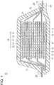
- Fig. 1 is a schematic cross-sectional view of a lithium-ion secondary battery according to one embodiment of the present invention.
- a cathode is a plate- or sheet-like battery member having a cathode active material layer formed by applying or rolling a mixture of a cathode active material, a binder, and an optional conduction aid onto a cathode current collector such as metallic foil, and drying the mixture.
- An anode is a plate- or sheet-like battery member having an anode active material layer formed by applying a mixture of an anode active material, a binder, and an optional conduction aid onto an anode current collector.
- a separator is a film-like battery member that separates the cathode from the anode for achieving conduction of lithium ions between the anode and the cathode.
- An electrolyte is an electroconductive solution obtained by dissolving an ionic substance in a solvent. In the present embodiment, the electrolyte may be a nonaqueous electrolyte.
- An electricity generation element including the cathode, the anode, the separator, and the electrolyte is a unit of main battery components. Typically, the cathode and the anode are superposed (or stacked) on each other with the separator between them, and the stack is immersed in the electrolyte.
- the lithium-ion secondary battery in the embodiment contains the electricity generation element in an enclosure.
- the electricity generation element may be sealed in the enclosure.
- the electricity generation element being sealed refers to the element being packaged by the enclosure and isolated from the outside air.
- the enclosure is thus a bag that can have the electricity generation element sealed inside.
- Anodes usable in all the embodiments include an anode in which an anode active material layer containing an anode active material is arranged on an anode current collector.
- the anode may include an anode active material layer formed by applying or rolling a mixture of an anode active material, a binder, and an optional conduction aid onto an anode current collector of metallic foil such as copper foil, and drying the mixture.
- the anode active material may include graphite. Graphite has a stable structure, and is suited to an anode material for a high-capacity battery.
- the anode active material may also include amorphous carbon, in addition to graphite particles. A mixed carbon material including both graphite and amorphous carbon improves the regeneration performance of the battery.
- Graphite also referred to as black lead, is a carbon material that is a hexagonal plate crystal. Graphite may be in the form of particles.
- Amorphous carbon is a generally amorphous carbon material with a network structure of randomly combined microcrystals. Amorphous carbon may also have a structure partially similar to a graphite structure. Examples of amorphous carbon include carbon black, coke, activated carbon, carbon fibers, hard carbon, soft carbon, and mesoporous carbon. Amorphous carbon may be in the form of particles.
- the conduction aid optionally used for the anode active material layer examples include carbon fibers such as carbon nanofibers, carbon black such as acetylene black and Ketjenblack, and carbon materials such as activated carbon, mesoporous carbon, fullerenes, and carbon nanotubes. Additionally, the anode active material layer may include, as appropriate, an additive commonly used for preparing an electrode, such as a thickener, a dispersant, or a stabilizer.
- binder used for the anode active material layer examples include fluorine resins such as polyvinylidene fluoride (PVDF), polytetrafluoroethylene (PTFE), and polyvinyl fluoride (PVF), conductive polymers such as polyanilines, polythiophenes, polyacetylenes, and polypyrroles, synthetic rubbers such as styrene-butadiene rubber (SBR), butadiene rubber (BR), chloroprene rubber (CR), isoprene rubber (IR), and acrylonitrile-butadiene rubber (NBR), or polysaccharides such as carboxymethylcellulose (CMC), xanthan gum, guar gum, and pectin.
- fluorine resins such as polyvinylidene fluoride (PVDF), polytetrafluoroethylene (PTFE), and polyvinyl fluoride (PVF)
- conductive polymers such as polyanilines, polythiophenes, polyacet
- Cathodes usable in all the embodiments include a cathode including a cathode active material layer containing a cathode active material arranged on a cathode current collector.
- the cathode may include a cathode active material layer formed by applying or rolling a mixture of a cathode active material, a binder, and an optional conduction aid onto a cathode current collector of metallic foil such as aluminum foil, and drying the mixture.
- the cathode active material may be a lithium transition metal oxide, such as a lithium nickel-based oxide (e.g., LiNiO 2 ), a lithium cobalt-based oxide (e.g., LiCoO 2 ), a lithium manganese-based oxide (e.g., LiMn 2 O 4 ), and a mixture of these.
- the cathode active material may also be a lithium-nickel-cobalt-manganese composite oxide represented by the general formula Li x Ni y Co z Mn (1-y-z) O 2 , where 1 ⁇ x ⁇ 1.2, y + z ⁇ 1 with y and z being positive numbers, and y is 0.5 or less.
- a larger ratio of manganese tends to prevent formation of a single phase composite oxide.
- the ratio of manganese is desirably 1-y-z ⁇ 0.4.
- a larger ratio of cobalt increases the cost and also reduces the capacity.
- the ratio of cobalt is desirably z ⁇ y and z ⁇ 1 - y - z.
- the ratio is preferably y > 1 - y - z and y > z.
- the lithium-nickel-cobalt-manganese composite oxide may have a layered crystal structure.
- the conduction aid optionally used for the cathode active material layer examples include carbon fibers such as carbon nanofibers, carbon black such as acetylene black and Ketjenblack, and carbon materials such as activated carbon, graphite, mesoporous carbon, fullerenes, and carbon nanotubes. Additionally, the cathode active material layer may include, as appropriate, an additive commonly used for preparing an electrode, such as a thickener, a dispersant, or a stabilizer.
- binder used for the cathode active material layer examples include fluorine resins such as polyvinylidene fluoride (PVDF), polytetrafluoroethylene (PTFE), and polyvinyl fluoride (PVF), conductive polymers such as polyanilines, polythiophenes, polyacetylenes, and polypyrroles, synthetic rubbers such as styrene-butadiene rubber (SBR), butadiene rubber (BR), chloroprene rubber (CR), isoprene rubber (IR), and acrylonitrile-butadiene rubber (NBR), or polysaccharides such as carboxymethylcellulose (CMC), xanthan gum, guar gum, and pectin.
- fluorine resins such as polyvinylidene fluoride (PVDF), polytetrafluoroethylene (PTFE), and polyvinyl fluoride (PVF)
- conductive polymers such as polyanilines, polythiophenes, polyace
- An electrolyte usable in all the embodiments may be a nonaqueous electrolyte and a mixture containing a chain carbonate such as dimethyl carbonate (DMC), diethyl carbonate (DEC), di-n-propyl carbonate, di-i-propyl carbonate, di-n-butyl carbonate, di-isobutyl carbonate, or di-t-butyl carbonate, and a cyclic carbonate such as propylene carbonate (PC) or ethylene carbonate (EC).
- a chain carbonate such as dimethyl carbonate (DMC), diethyl carbonate (DEC), di-n-propyl carbonate, di-i-propyl carbonate, di-n-butyl carbonate, di-isobutyl carbonate, or di-t-butyl carbonate
- PC propylene carbonate
- EC ethylene carbonate
- the electrolyte is obtained by dissolving a lithium salt such as lithium hexafluorophosphate (LiPF 6 ), lithium tetrafluoroborate (LiBF 4 ), or lithium perchlorate (LiClO 4 ) in such a carbonate mixture.
- a lithium salt such as lithium hexafluorophosphate (LiPF 6 ), lithium tetrafluoroborate (LiBF 4 ), or lithium perchlorate (LiClO 4 ) in such a carbonate mixture.
- the electrolyte may contain additives, in addition to the above components.
- the additives optionally added to the electrolyte may be substances that electrochemically decompose during the charging and discharging process of the battery to cover the electrodes and other parts with coatings.
- an additive for stabilizing the anode structure on the anode surface may be desirably used.
- additives include an additive containing a compound with sulfur in its molecule (hereinafter, a sulfur-containing additive), such as cyclic disulfonates (e.g., methylene methane disulfonate, ethylene methane disulfonate, and propylene methane disulfonate), cyclic sulfonates (e.g., sultone), and chain sulfonates (e.g., methylene-bis(benzenesulfonate), methylene-bis(phenylmethanesulfonate), and methylene-bis(ethanesulfonate)).
- a sulfur-containing additive such as cyclic disulfonates (e.g., methylene methane disulfonate, ethylene methane disulfonate, and propylene methane disulfonate), cyclic sulfonates (e.g., sultone), and chain sulfonates (e
- vinylene carbonate, vinylethylene carbonate, propylene carbonate methacrylate, and propylene carbonate acrylate may also be additives for covering the cathode and the anode with protective coatings during the charging and discharging process of the battery.
- the additives for covering the cathode and the anode with protective coatings during the charging and discharging process of the battery include fluoroethylene carbonate, difluoroethylene carbonate, trifluoroethylene carbonate, chloroethylene carbonate, dichloroethylene carbonate, and trichloroethylene carbonate. These additives may protect the cathode active material containing the lithium nickel-based composite oxide against an attack from the sulfur-containing additive.
- the additives constitute an amount of not more than 20% by weight, preferably not more than 15% by weight, and further preferably not more than 10% by weight relative to the weight of the overall electrolyte.
- the separator includes an olefinic resin layer.
- the olefinic resin layer is formed from a polyolefin produced by polymerizing or copolymerizing • -olefins such as ethylene, propylene, butene, pentene, and hexene.
- the olefinic resin layer may have holes that close upon an increase in the battery temperature. More specifically, the layer may be formed from a porous or microporous polyolefin. If the battery temperature increases, the olefinic resin layer having this structure allows the separator to close (or shut down), and blocks the ion flow. To achieve a shutdown, a porous polyethylene film is suitable.
- a separator may include a cross-linked olefinic resin.
- a cross-linked olefinic resin examples include a chemically cross-linked polymer using a polyfunctional substance containing multiple polymerizable groups in a single molecule (e.g., trimethylolpropane triacrylate, trimethylolpropane trimethacrylate, pentaerythritol triacrylate, and pentaerythritol trimethacrylate), and an electronically cross-linked polymer polymerized by generating a radical using ionizing radiation.
- the separator may have a thermal shrinkage percentage of 13% or less.
- the thermal shrinkage percentage of film materials including the separator is a value indicating a dimensional change (reduction) caused when heat is applied to the film materials, and is calculated based on, for example, JIS-C-2151, JIS-C-2318, and ASTMDD-1204.
- the value of the thermal shrinkage percentage herein represents a shrinkage in the area of a sample piece of the film materials. The sample piece is suspended in a hot-air circulating thermostatic oven, the thermostatic oven is heated from 25 to 180 °C for 30 minutes, and then the thermostatic oven is cooled to room temperature before the shrinkage is measured.
- the thermal shrinkage percentage can be calculated using the formula: 100 ⁇ the area of the film material before the test ⁇ the area of the film material after the test / the area of the film material before the test .
- heat generated by a micro short circuit may increase the area of film breakage, and causes a high current to flow.
- the separator may include both the olefinic resin layer and a heat-resistant fine-particle layer.
- the separator including a heat-resistant fine-particle layer prevents the battery from heating and reduces thermal shrinkage in the separator.
- the heat-resistant fine particles may be inorganic fine particles that are heat-resistant to withstand temperatures up to 150 °C or more and stable against electrochemical reactions.
- Examples of the inorganic fine particles include inorganic oxides such as silica, alumina (• -alumina, • -alumina, or •-alumina), iron oxide, titanium oxide, barium titanate, and zirconium oxide, and minerals such as boehmite, zeolite, apatite, kaolin, spinel, mica, and mullite.
- the separator including the olefinic resin layer and the heat-resistant resin layer in this manner may be herein referred to as a ceramic separator.
- the ceramic separator including the olefinic resin layer and the heat-resistant fine-particle layer has the heat-resistant fine-particle layer stacked on the surface of an olefinic resin film.
- the heat-resistant fine-particle layer may be arranged on one side or both sides of the olefinic resin film.
- the thickness ratio of the entire heat-resistant fine-particle layer to the olefinic resin layer is about 1/10 to 1/2, and preferably about 1/8 to 1/3.
- the excessively high thickness of the heat-resistant fine-particle layer may increase the amount of sulfur-containing additive decomposition products contained in the electrolyte.
- the excessively low thickness of the heat-resistant fine-particle layer may not improve the heat resistance of the separator.
- Fig. 1 shows an example cross-sectional view of the lithium-ion secondary battery.
- the lithium-ion secondary battery 10 includes an anode current collector 11, an anode active material layer 13, a separator 17, a cathode current collector 12, and a cathode active material layer 15 as main components.
- Fig. 1 shows the anode active material layer 13 arranged on both sides of the anode current collector 11 and the cathode active material layer 15 arranged on both sides of the cathode current collector 12, each active material layer may be formed on only one side of the corresponding current collector.
- the anode current collector 11, the cathode current collector 12, the anode active material layer 13, the cathode active material layer 15, and the separator 17 are a single unit of the battery, or an electricity generation element (a cell 19 in the figure).
- the separator 17 may include a heat-resistant fine-particle layer and an olefinic resin film (both not shown). Such a plurality of cells 19 are stacked on one another with separators 17 between them.
- the extensions from the anode current collectors 11 are collectively bonded to an anode lead 25, whereas the extensions from the cathode current collectors 12 are collectively bonded to a cathode lead 27.
- the cathode lead may be an aluminum sheet, and the anode lead may be a copper sheet.
- each lead may be coated by other metals (e.g., nickel, tin, and solder) or a high polymer material.
- the cathode lead is welded to the cathode, and the anode lead to the anode.
- the stack of the multiple cells is packaged in an enclosure 29 with the welded anode lead 25 and the welded cathode lead 27 extending outward.
- the enclosure 29 is filled with an electrolyte 31.
- the enclosure 29 is formed by bonding the peripheral edges of two superposed laminates by heat fusion.
- anode lead 25 and the cathode lead 27 provided at opposing sides of the enclosure 29 (double-sided tab), the anode lead 25 and the cathode lead 27 may also be provided at one side of the enclosure 29 (more specifically, the anode lead 25 and the cathode lead 27 may extend outward from one side of the enclosure 29, or single-sided tab).
- the ratio between the cathode specific capacity and the anode specific capacity may be 1 or higher.
- the lithium-ion secondary battery charged to 5 V corresponds to the battery charged into an overcharge state.
- the proper balance between the cathode specific capacity (or the ability of the cathode to discharge lithium ions per unit volume) and the anode specific capacity (or the ability of the anode to hold lithium ions per unit volume) ensures the safety of the overcharged battery.
- the ratio between the cathode specific capacity and the anode specific capacity is lower than 1, the anode capacity exceeds the cathode capacity, and thus the battery capacity may decrease.
- the ratio between the cathode specific capacity and the anode specific capacity can be increased to 1 or higher by choosing an appropriate electrode active material or changing the combination ratio of the electrode active materials and the other additives. For example, a larger amount of the cathode active material may be applied to the cathode current collector, or a smaller amount of the anode active material may be applied to the anode current collector.
- the ratio between the cathode specific capacity and the anode specific capacity determined when the lithium-ion secondary battery is charged to 5 V may be 2 or lower.
- the ratio between the cathode specific capacity and the anode specific capacity is preferably 1.5 or lower, and further preferably 1.1 or lower.
- the ratio between the cathode specific capacity and the anode specific capacity determined when the lithium-ion secondary battery is charged to 5 V may be herein referred to as an excess ratio.
- the anode and the cathode may be prepared to have the ratio between the anode capacity (A) and the cathode capacity (C) (hereinafter A/C ratio) of 1.25 or less.
- a high A/C ratio represents a large lithium-ion capacity of one anode relative to the amount of lithium-ion discharge from one cathode, meaning that the anode holds a large amount of lithium ions.
- the overcharged battery may not maintain safety.
- the A/C ratio is to be maintained at a proper value.
- the A/C ratio is desirably 1.05 or higher.
- the ratio between the battery power and the battery capacity may be less than 25.
- the battery power represents the average output power over 10 seconds.
- multiple batteries are combined to form a set battery (battery pack). In this case, each battery may have output power that is not too high.
- the ratio between the battery power and the battery capacity may be 2 or more and less than 25. With the on-vehicle battery having a power-capacity ratio lower than 2, the battery cannot follow the load characteristics due to high resistance.
- the battery may have an insufficient capacity per area due to a typical use of a thin-film electrode.
- the power-capacity ratio is preferably 5 or more and 20 or less, and further preferably 10 or more and 15 or less.
- a battery to be used in a high-capacity battery pack is highly preferable to have a battery capacity of 5 Ah or higher.
- the battery capacity is preferably 5 Ah or more and 70 Ah or less.
- the battery capacity is further preferably 45 Ah or more and 55 Ah or less.
- Another anode was prepared. Hard carbon (400 mAh/g) as an anode active material; and carbon black powder as a conduction aid, and PVDF as a binder resin were added to deionized water in a solid content mass ratio of 94:6. The water was then stirred to disperse these materials uniformly to form slurry. The slurry was applied to an 8-• m-thick piece of copper foil to be an anode current collector. Then, the electrode was heated at 125 °C for ten minutes to evaporate the water to form an anode active material layer. Additionally, the anode active material layer was pressed to have a porosity of 35%. The anode active material layer was applied to one surface of the anode current collector to complete the anode. In Table 1, HC is this anode.
- NCM Lithium nickel cobalt manganese oxide
- carbon black powder as a conduction aid
- PVDF Kureha Battery Materials Japan Co., Ltd.
- NMP N-methyl-pyrrolidone
- Anhydrous oxalic acid molecular weight: 90 was added to this mixture as an organic moisture absorbent in an amount of 0.03 parts by mass based on 100 parts by mass in terms of solid content excluding the NMP from the mixture.
- the mixture was then stirred to disperse these materials uniformly to form slurry.
- the slurry was applied to a 15-• m-thick piece of aluminum foil to be a cathode current collector.
- a cathode active material layer was formed by heating the electrode at 125 °C for ten minutes to evaporate the NMP. Additionally, the cathode active material layer was pressed to have a porosity of 25%. The cathode active material layer was applied to one surface of the cathode current collector to complete the cathode.
- a composite cathode was further prepared.
- a composite cathode active material including lithium nickel cobalt manganese oxide (NCM433; nickel:cobalt:manganese 4:3:3) and LiMnO 2 with a 10-• m particle size (D50) (hereinafter, LMO1) mixed in a ratio indicated in Table 1, carbon black powder as a conduction aid, and PVDF (Kureha W#7200, Kureha Battery Materials Japan Co., Ltd.) as a binder resin were added to NMP, which is a solvent.
- the solid content mass ratio of the cathode active material to the conduction aid and the binder resin was 90:5:5.
- Anhydrous oxalic acid (molecular weight: 90) was added to this mixture as an organic moisture absorbent in an amount of 0.03 parts by mass based on 100 parts by mass in terms of solid content excluding the NMP from the mixture.
- the mixture was then stirred to disperse these materials uniformly to form slurry.
- the slurry was applied to a 15-• m-thick piece of aluminum foil to be a cathode current collector.
- a cathode active material layer was formed by heating the electrode at 125 °C for ten minutes to evaporate the NMP. Additionally, the cathode active material layer was pressed to have a porosity of 30%.
- the cathode active material layer was applied to one surface of the cathode current collector to complete the cathode.
- Ethylene carbonate (EC), propylene carbonate (PC), and diethyl carbonate (DEC) were mixed in a nonaqueous solvent.
- the mixture ratio of EC to PC and DEC was 25:5:70 (by volume).
- lithium hexafluorophosphate (LiPF 6 ) was dissolved as an electrolyte salt at a concentration of 0.9 mol/L.
- cyclic disulfonate methylene methanedisulfonate, or MMDS
- vinylene carbonate (VC) were each dissolved as additives at a concentration of 1 wt %. The resulting electrolyte was used.
- the anode and cathode plates prepared in the manner described above were each cut into a predetermined-sized (anode: 254 mm ⁇ 184 mm, cathode: 250 mm ⁇ 180 mm) rectangle.
- a cathode plate uncoated part for connecting a terminal was ultrasonically welded to an aluminum cathode lead terminal.
- an anode plate uncoated part was ultrasonically welded to a nickel anode lead terminal having the same size as the cathode lead terminal.
- the anode plate and the cathode plate were arranged on both separator sides to have the anode and cathode active material layers superposed on each other with the separator between them, and aligned the cathode lead and the anode lead at one side.
- Two aluminum laminated films were bonded together by heat fusion of the corresponding sides excluding one long side of each film to prepare a bag-shaped laminated enclosure.
- the electrode stack was inserted in the laminated enclosure.
- the enclosure was then filled with the electrolyte to vacuum-impregnate the electrode stack.
- the opening was heat-sealed under reduced pressure to form a single-sided-tab stacked lithium-ion battery.
- the stacked lithium-ion battery underwent the initial charge and discharge, which is followed by high-temperature aging. This completes the stacked lithium-ion battery with a battery capacity of 5 Ah.
- the initial charge and discharge were performed between 0 and 100% of the battery remaining capacity, or the state of charge (SOC) at an ambient temperature of 55 °C.
- the charge and discharge were performed in the order of constant current charge (CC charge) to 4.1 V with 0.1 C current, constant voltage charge (CV charge) at 4.1 V, and constant current discharge (CC discharge) to 2.5 V with 0.1 C current.
- the battery with the SOC of 0% was charged to a battery voltage of 5 V with 1 C current.
- the battery capacity (defined as X mAh) was measured and determined to be a cathode overcharge capacity.
- the prepared battery was discharged to a battery voltage of 4.15 V, and placed in the thermostatic oven.
- the temperature inside the thermostatic oven was increased to 150 °C in increments of 1 °C per minute.
- the ambient temperature reached 150 °C, a change in the battery voltage was measured.
- the battery states at this time were classified into three types: the battery on fire (burning), the battery generating heat (heating), and no change observed in the battery voltage and the battery temperature (no change).
- the battery with the SOC of 0% was disassembled, and the total area of the cathode was measured (a cm 2 ).
- the anode was removed from the disassembled battery, washed with an EC/DEC solvent, and punched into a coin shape with a diameter of 12 mm.
- the coin-shaped anode was used to prepare a coin cell with metal lithium as a cathode.
- the coin cell was CC/CV-charged for 24 hours with 0.1 C current, and its capacity (defined as Y mAh) was measured.
- the anode capacity per area, y was calculated (mAh/cm 2 ) and determined to be the anode specific capacity.
- the value y is herein assumed to be substantially the same as the anode overcharge capacity, and is used in the calculation below.
- the excess ratio was determined by dividing the value x by the value y (x/y).
- the excess ratio which is a value of the cathode overcharge specific capacity relative to the anode specific capacity, indicates the balance between the amount of lithium ions discharged from the cathode and the allowable amount of lithium ions held by the anode as described above.
- the battery was CC-charged from a battery voltage of 3V to the SOC of 50% with 0.2 CC current. The battery was allowed to stand in this state for one hour. Then, the battery voltage was determined to be the SOC of 50%-OCV (V), or a value of the open circuit voltage of the battery with a 50% remaining capacity.
- V 50%-OCV
- the maximum current value for achieving the lowest voltage (3V) at 25 °C for 10 seconds from the 50% SOC-OCV was measured.
- the product of the value of 50% SOC-OCV by the maximum current value (A) was determined to be the battery power (W).
- the separator was suspended in a hot-air circulating thermostatic oven, and was heated from 25 to 180 °C for 30 minutes, and then cooled to room temperature before the area of the sample piece was measured.
- the thermal shrinkage was calculated using the formula: 100 ⁇ [(the area of the separator before the test) - (the area of the separator after the test)] / (the area of the separator before the test).
- the excess ratio increases as the proportion of NCM in the composite cathode increases.
- comparative examples 2 and 3 in which graphite was used as an anode material and the excess ratio exceeded 100%, heating was observed in the heating test.
- reference examples 3 and 4 in which hard carbon was used as an anode material and the excess ratio exceeded 100%, no change was observed in the heating test.
- the results suggest that a smaller proportion of NCM in the composite cathode and an anode material of hard carbon can yield good results at least in a heating test.
- To use a lithium-ion secondary battery as an on-vehicle large-capacity battery (1) the proportion of NCM in the composite cathode is to be maximized, and (2) graphite is to be used as an anode material.
- Examples 1 to 5 are experimental examples in which a separator having a thermal shrinkage of 13% or less was used. Heating was not observed in the heating test in any of the examples. Although the battery according to each example shows an excess ratio of more than 100%, the separator can prevent an increase in the battery temperature. In contrast, heating was observed in the heating test in comparative example 1, in which the excess ratio exceeded 100% and the separator showed a thermal shrinkage of more than 13%. More specifically, a safe battery with a large capacity and a high energy density can be obtained by selecting an appropriate separator based on the combination of electrode materials and the ratio between the electrode specific capacities.
Landscapes
- Chemical & Material Sciences (AREA)
- Chemical Kinetics & Catalysis (AREA)
- Electrochemistry (AREA)
- General Chemical & Material Sciences (AREA)
- Engineering & Computer Science (AREA)
- Materials Engineering (AREA)
- Inorganic Chemistry (AREA)
- Manufacturing & Machinery (AREA)
- Condensed Matter Physics & Semiconductors (AREA)
- General Physics & Mathematics (AREA)
- Physics & Mathematics (AREA)
- Secondary Cells (AREA)
- Battery Electrode And Active Subsutance (AREA)
- Cell Separators (AREA)
Abstract
Description
- The present invention relates to a nonaqueous-electrolyte battery, and more particularly, to a lithium-ion secondary battery.
- Nonaqueous-electrolyte batteries are used for automobiles including hybrid vehicles and electric vehicles. Lithium-ion secondary batteries are commonly used as such on-vehicle batteries. As lithium-ion secondary batteries have larger capacity through development efforts, their safety needs to be ensured.
- A lithium-ion secondary battery charged after fully charged can typically be in an overcharge state, which is unstable. A lithium-ion secondary battery using, as its cathode material, a lithium composite oxide with a layered crystal structure having a high energy density can have an overcharge state, in which lithium ions continuously move from the cathode (positive electrode) to the anode (negative electrode). The limited capacity of the anode for lithium ions (or anode capacity) can then cause overflow of lithium ions from the anode.
- One method for preventing such overcharge includes monitoring the voltage of a lithium-ion secondary battery to prevent an overcharge. Another method includes adding a particular additive to an electrolyte for electrochemical overcharge protection.
- Japanese Unexamined Patent Application Publication No.
2013-178936 2013-178936 2013-178936 - One or more aspects of the present invention are directed to a lithium-ion secondary battery that prevents heat generation in an overcharge state and maintains safety.
- A lithium-ion secondary battery according to an aspect of the present invention includes an electricity generation element including a cathode including a cathode active material layer arranged on a cathode current collector, an anode including an anode active material layer arranged on an anode current collector, a separator, and an electrolyte. The anode active material layer includes graphite. When the battery is charged to 5 V, the battery has an excess ratio of 1 or higher that is a specific capacity of the cathode to a specific capacity of the anode, and the separator has a thermal shrinkage of 13% or lower.
- The lithium-ion secondary battery according to the above aspects of the present invention maintains safety, and is less likely to generate internal heat in an overcharge state and thus prevents an increase in the battery temperature.
-
Fig. 1 is a schematic cross-sectional view of a lithium-ion secondary battery according to one embodiment of the present invention. - Embodiments of the present invention will now be described. In the present embodiment, a cathode is a plate- or sheet-like battery member having a cathode active material layer formed by applying or rolling a mixture of a cathode active material, a binder, and an optional conduction aid onto a cathode current collector such as metallic foil, and drying the mixture. An anode is a plate- or sheet-like battery member having an anode active material layer formed by applying a mixture of an anode active material, a binder, and an optional conduction aid onto an anode current collector. A separator is a film-like battery member that separates the cathode from the anode for achieving conduction of lithium ions between the anode and the cathode. An electrolyte is an electroconductive solution obtained by dissolving an ionic substance in a solvent. In the present embodiment, the electrolyte may be a nonaqueous electrolyte. An electricity generation element including the cathode, the anode, the separator, and the electrolyte is a unit of main battery components. Typically, the cathode and the anode are superposed (or stacked) on each other with the separator between them, and the stack is immersed in the electrolyte.
- The lithium-ion secondary battery in the embodiment contains the electricity generation element in an enclosure. The electricity generation element may be sealed in the enclosure. The electricity generation element being sealed refers to the element being packaged by the enclosure and isolated from the outside air. The enclosure is thus a bag that can have the electricity generation element sealed inside.
- Anodes usable in all the embodiments include an anode in which an anode active material layer containing an anode active material is arranged on an anode current collector. In some embodiments, the anode may include an anode active material layer formed by applying or rolling a mixture of an anode active material, a binder, and an optional conduction aid onto an anode current collector of metallic foil such as copper foil, and drying the mixture. In each embodiment, the anode active material may include graphite. Graphite has a stable structure, and is suited to an anode material for a high-capacity battery. The anode active material may also include amorphous carbon, in addition to graphite particles. A mixed carbon material including both graphite and amorphous carbon improves the regeneration performance of the battery.
- Graphite, also referred to as black lead, is a carbon material that is a hexagonal plate crystal. Graphite may be in the form of particles. Amorphous carbon is a generally amorphous carbon material with a network structure of randomly combined microcrystals. Amorphous carbon may also have a structure partially similar to a graphite structure. Examples of amorphous carbon include carbon black, coke, activated carbon, carbon fibers, hard carbon, soft carbon, and mesoporous carbon. Amorphous carbon may be in the form of particles.
- Examples of the conduction aid optionally used for the anode active material layer include carbon fibers such as carbon nanofibers, carbon black such as acetylene black and Ketjenblack, and carbon materials such as activated carbon, mesoporous carbon, fullerenes, and carbon nanotubes. Additionally, the anode active material layer may include, as appropriate, an additive commonly used for preparing an electrode, such as a thickener, a dispersant, or a stabilizer.
- Examples of the binder used for the anode active material layer include fluorine resins such as polyvinylidene fluoride (PVDF), polytetrafluoroethylene (PTFE), and polyvinyl fluoride (PVF), conductive polymers such as polyanilines, polythiophenes, polyacetylenes, and polypyrroles, synthetic rubbers such as styrene-butadiene rubber (SBR), butadiene rubber (BR), chloroprene rubber (CR), isoprene rubber (IR), and acrylonitrile-butadiene rubber (NBR), or polysaccharides such as carboxymethylcellulose (CMC), xanthan gum, guar gum, and pectin.
- Cathodes usable in all the embodiments include a cathode including a cathode active material layer containing a cathode active material arranged on a cathode current collector. In some embodiments, the cathode may include a cathode active material layer formed by applying or rolling a mixture of a cathode active material, a binder, and an optional conduction aid onto a cathode current collector of metallic foil such as aluminum foil, and drying the mixture. The cathode active material may be a lithium transition metal oxide, such as a lithium nickel-based oxide (e.g., LiNiO2), a lithium cobalt-based oxide (e.g., LiCoO2), a lithium manganese-based oxide (e.g., LiMn2O4), and a mixture of these. The cathode active material may also be a lithium-nickel-cobalt-manganese composite oxide represented by the general formula LixNiyCozMn(1-y-z)O2, where 1 ≤ x ≤ 1.2, y + z < 1 with y and z being positive numbers, and y is 0.5 or less. A larger ratio of manganese tends to prevent formation of a single phase composite oxide. Thus, the ratio of manganese is desirably 1-y-z ≤ 0.4. In addition, a larger ratio of cobalt increases the cost and also reduces the capacity. Thus, the ratio of cobalt is desirably z < y and z < 1 - y - z. To achieve a high-capacity battery, the ratio is preferably y > 1 - y - z and y > z. The lithium-nickel-cobalt-manganese composite oxide may have a layered crystal structure.
- Examples of the conduction aid optionally used for the cathode active material layer include carbon fibers such as carbon nanofibers, carbon black such as acetylene black and Ketjenblack, and carbon materials such as activated carbon, graphite, mesoporous carbon, fullerenes, and carbon nanotubes. Additionally, the cathode active material layer may include, as appropriate, an additive commonly used for preparing an electrode, such as a thickener, a dispersant, or a stabilizer.
- Examples of the binder used for the cathode active material layer include fluorine resins such as polyvinylidene fluoride (PVDF), polytetrafluoroethylene (PTFE), and polyvinyl fluoride (PVF), conductive polymers such as polyanilines, polythiophenes, polyacetylenes, and polypyrroles, synthetic rubbers such as styrene-butadiene rubber (SBR), butadiene rubber (BR), chloroprene rubber (CR), isoprene rubber (IR), and acrylonitrile-butadiene rubber (NBR), or polysaccharides such as carboxymethylcellulose (CMC), xanthan gum, guar gum, and pectin.
- An electrolyte usable in all the embodiments may be a nonaqueous electrolyte and a mixture containing a chain carbonate such as dimethyl carbonate (DMC), diethyl carbonate (DEC), di-n-propyl carbonate, di-i-propyl carbonate, di-n-butyl carbonate, di-isobutyl carbonate, or di-t-butyl carbonate, and a cyclic carbonate such as propylene carbonate (PC) or ethylene carbonate (EC). The electrolyte is obtained by dissolving a lithium salt such as lithium hexafluorophosphate (LiPF6), lithium tetrafluoroborate (LiBF4), or lithium perchlorate (LiClO4) in such a carbonate mixture.
- The electrolyte may contain additives, in addition to the above components. The additives optionally added to the electrolyte may be substances that electrochemically decompose during the charging and discharging process of the battery to cover the electrodes and other parts with coatings. In particular, an additive for stabilizing the anode structure on the anode surface may be desirably used. Examples of such additives include an additive containing a compound with sulfur in its molecule (hereinafter, a sulfur-containing additive), such as cyclic disulfonates (e.g., methylene methane disulfonate, ethylene methane disulfonate, and propylene methane disulfonate), cyclic sulfonates (e.g., sultone), and chain sulfonates (e.g., methylene-bis(benzenesulfonate), methylene-bis(phenylmethanesulfonate), and methylene-bis(ethanesulfonate)). Moreover, vinylene carbonate, vinylethylene carbonate, propylene carbonate methacrylate, and propylene carbonate acrylate may also be additives for covering the cathode and the anode with protective coatings during the charging and discharging process of the battery. Other examples of the additives for covering the cathode and the anode with protective coatings during the charging and discharging process of the battery include fluoroethylene carbonate, difluoroethylene carbonate, trifluoroethylene carbonate, chloroethylene carbonate, dichloroethylene carbonate, and trichloroethylene carbonate. These additives may protect the cathode active material containing the lithium nickel-based composite oxide against an attack from the sulfur-containing additive. The additives constitute an amount of not more than 20% by weight, preferably not more than 15% by weight, and further preferably not more than 10% by weight relative to the weight of the overall electrolyte.
- In an embodiment, the separator includes an olefinic resin layer. The olefinic resin layer is formed from a polyolefin produced by polymerizing or copolymerizing • -olefins such as ethylene, propylene, butene, pentene, and hexene. In an embodiment, the olefinic resin layer may have holes that close upon an increase in the battery temperature. More specifically, the layer may be formed from a porous or microporous polyolefin. If the battery temperature increases, the olefinic resin layer having this structure allows the separator to close (or shut down), and blocks the ion flow. To achieve a shutdown, a porous polyethylene film is suitable.
- A separator may include a cross-linked olefinic resin. Examples of such a resin include a chemically cross-linked polymer using a polyfunctional substance containing multiple polymerizable groups in a single molecule (e.g., trimethylolpropane triacrylate, trimethylolpropane trimethacrylate, pentaerythritol triacrylate, and pentaerythritol trimethacrylate), and an electronically cross-linked polymer polymerized by generating a radical using ionizing radiation.
- In particular, the separator may have a thermal shrinkage percentage of 13% or less. The thermal shrinkage percentage of film materials including the separator is a value indicating a dimensional change (reduction) caused when heat is applied to the film materials, and is calculated based on, for example, JIS-C-2151, JIS-C-2318, and ASTMDD-1204. The value of the thermal shrinkage percentage herein represents a shrinkage in the area of a sample piece of the film materials. The sample piece is suspended in a hot-air circulating thermostatic oven, the thermostatic oven is heated from 25 to 180 °C for 30 minutes, and then the thermostatic oven is cooled to room temperature before the shrinkage is measured. In other words, the thermal shrinkage percentage can be calculated using the formula:

- For a separator having a thermal shrinkage percentage of more than 13%, heat generated by a micro short circuit may increase the area of film breakage, and causes a high current to flow.
- The separator may include both the olefinic resin layer and a heat-resistant fine-particle layer. The separator including a heat-resistant fine-particle layer prevents the battery from heating and reduces thermal shrinkage in the separator. The heat-resistant fine particles may be inorganic fine particles that are heat-resistant to withstand temperatures up to 150 °C or more and stable against electrochemical reactions. Examples of the inorganic fine particles include inorganic oxides such as silica, alumina (• -alumina, • -alumina, or •-alumina), iron oxide, titanium oxide, barium titanate, and zirconium oxide, and minerals such as boehmite, zeolite, apatite, kaolin, spinel, mica, and mullite. The separator including the olefinic resin layer and the heat-resistant resin layer in this manner may be herein referred to as a ceramic separator.
- The ceramic separator including the olefinic resin layer and the heat-resistant fine-particle layer has the heat-resistant fine-particle layer stacked on the surface of an olefinic resin film. The heat-resistant fine-particle layer may be arranged on one side or both sides of the olefinic resin film. The thickness ratio of the entire heat-resistant fine-particle layer to the olefinic resin layer is about 1/10 to 1/2, and preferably about 1/8 to 1/3. The excessively high thickness of the heat-resistant fine-particle layer may increase the amount of sulfur-containing additive decomposition products contained in the electrolyte. The excessively low thickness of the heat-resistant fine-particle layer may not improve the heat resistance of the separator.
- The structure of the lithium-ion secondary battery according to the present embodiment will now be described with reference to the drawings.
Fig. 1 shows an example cross-sectional view of the lithium-ion secondary battery. The lithium-ionsecondary battery 10 includes an anodecurrent collector 11, an anodeactive material layer 13, aseparator 17, a cathodecurrent collector 12, and a cathodeactive material layer 15 as main components. AlthoughFig. 1 shows the anodeactive material layer 13 arranged on both sides of the anodecurrent collector 11 and the cathodeactive material layer 15 arranged on both sides of the cathodecurrent collector 12, each active material layer may be formed on only one side of the corresponding current collector. The anodecurrent collector 11, the cathodecurrent collector 12, the anodeactive material layer 13, the cathodeactive material layer 15, and theseparator 17 are a single unit of the battery, or an electricity generation element (acell 19 in the figure). Theseparator 17 may include a heat-resistant fine-particle layer and an olefinic resin film (both not shown). Such a plurality ofcells 19 are stacked on one another withseparators 17 between them. The extensions from the anodecurrent collectors 11 are collectively bonded to ananode lead 25, whereas the extensions from the cathodecurrent collectors 12 are collectively bonded to acathode lead 27. The cathode lead may be an aluminum sheet, and the anode lead may be a copper sheet. In some cases, each lead may be coated by other metals (e.g., nickel, tin, and solder) or a high polymer material. The cathode lead is welded to the cathode, and the anode lead to the anode. The stack of the multiple cells is packaged in anenclosure 29 with the weldedanode lead 25 and the weldedcathode lead 27 extending outward. Theenclosure 29 is filled with anelectrolyte 31. Theenclosure 29 is formed by bonding the peripheral edges of two superposed laminates by heat fusion. AlthoughFig. 1 shows theanode lead 25 and thecathode lead 27 provided at opposing sides of the enclosure 29 (double-sided tab), theanode lead 25 and thecathode lead 27 may also be provided at one side of the enclosure 29 (more specifically, theanode lead 25 and thecathode lead 27 may extend outward from one side of theenclosure 29, or single-sided tab). - When the lithium-ion secondary battery prepared in this manner is charged to 5 V, the ratio between the cathode specific capacity and the anode specific capacity may be 1 or higher. The lithium-ion secondary battery charged to 5 V corresponds to the battery charged into an overcharge state. In an overcharge state, the proper balance between the cathode specific capacity (or the ability of the cathode to discharge lithium ions per unit volume) and the anode specific capacity (or the ability of the anode to hold lithium ions per unit volume) ensures the safety of the overcharged battery. When the ratio between the cathode specific capacity and the anode specific capacity is lower than 1, the anode capacity exceeds the cathode capacity, and thus the battery capacity may decrease. The ratio between the cathode specific capacity and the anode specific capacity can be increased to 1 or higher by choosing an appropriate electrode active material or changing the combination ratio of the electrode active materials and the other additives. For example, a larger amount of the cathode active material may be applied to the cathode current collector, or a smaller amount of the anode active material may be applied to the anode current collector. To maintain the proper balance between the cathode specific capacity and the anode specific capacity, the ratio between the cathode specific capacity and the anode specific capacity determined when the lithium-ion secondary battery is charged to 5 V may be 2 or lower. The ratio between the cathode specific capacity and the anode specific capacity is preferably 1.5 or lower, and further preferably 1.1 or lower. The ratio between the cathode specific capacity and the anode specific capacity determined when the lithium-ion secondary battery is charged to 5 V may be herein referred to as an excess ratio.
- The anode and the cathode may be prepared to have the ratio between the anode capacity (A) and the cathode capacity (C) (hereinafter A/C ratio) of 1.25 or less. A high A/C ratio represents a large lithium-ion capacity of one anode relative to the amount of lithium-ion discharge from one cathode, meaning that the anode holds a large amount of lithium ions. At an excessively large anode capacity, the overcharged battery may not maintain safety. Thus, the A/C ratio is to be maintained at a proper value. To achieve a large battery capacity, the A/C ratio is desirably 1.05 or higher.
- In another embodiment, the ratio between the battery power and the battery capacity (W/Wh) may be less than 25. The battery power represents the average output power over 10 seconds. To provide a high-capacity lithium-ion secondary battery for a vehicle having a cruising range of more than 100 km, multiple batteries (cells) are combined to form a set battery (battery pack). In this case, each battery may have output power that is not too high. The ratio between the battery power and the battery capacity (power-capacity ratio) may be 2 or more and less than 25. With the on-vehicle battery having a power-capacity ratio lower than 2, the battery cannot follow the load characteristics due to high resistance. In contrast, with the battery having a power-capacity ratio equal to or higher than 25, the battery may have an insufficient capacity per area due to a typical use of a thin-film electrode. The power-capacity ratio is preferably 5 or more and 20 or less, and further preferably 10 or more and 15 or less.
- A battery to be used in a high-capacity battery pack is highly preferable to have a battery capacity of 5 Ah or higher. To achieve the proper balance of the power-capacity ratio described above, the battery capacity is preferably 5 Ah or more and 70 Ah or less. The battery capacity is further preferably 45 Ah or more and 55 Ah or less.
- Surface-covered natural graphite powder (specific capacity: 390 mAh/g) as an anode active material; and carbon black powder as a conduction aid, and a polyvinylidene fluoride resin (PVDF, Kureha W#7200, Kureha Battery Materials Japan Co., Ltd.) as a binder resin were added to deionized water in a solid content mass ratio of 94:6. The water was then stirred to disperse these materials uniformly in the water to form slurry. The slurry was applied to an 8-• m-thick piece of copper foil to be an anode current collector. Then, the electrode was heated at 125 °C for ten minutes to evaporate the water to form an anode active material layer. Additionally, the anode active material layer was pressed to have a porosity of 35%. The anode active material layer was applied to one surface of the anode current collector to complete the anode. In Table 1, Gr is this anode.
- Another anode was prepared. Hard carbon (400 mAh/g) as an anode active material; and carbon black powder as a conduction aid, and PVDF as a binder resin were added to deionized water in a solid content mass ratio of 94:6. The water was then stirred to disperse these materials uniformly to form slurry. The slurry was applied to an 8-• m-thick piece of copper foil to be an anode current collector. Then, the electrode was heated at 125 °C for ten minutes to evaporate the water to form an anode active material layer. Additionally, the anode active material layer was pressed to have a porosity of 35%. The anode active material layer was applied to one surface of the anode current collector to complete the anode. In Table 1, HC is this anode.
- Lithium nickel cobalt manganese oxide (NCM433; nickel:cobalt:manganese = 4:3:3, hereinafter NCM) as a cathode active material, carbon black powder as a conduction aid, and PVDF (Kureha W#7200, Kureha Battery Materials Japan Co., Ltd.) as a binder resin were added to N-methyl-pyrrolidone (NMP), a solvent, in a solid content mass ratio of 93:3:4. Anhydrous oxalic acid (molecular weight: 90) was added to this mixture as an organic moisture absorbent in an amount of 0.03 parts by mass based on 100 parts by mass in terms of solid content excluding the NMP from the mixture. The mixture was then stirred to disperse these materials uniformly to form slurry. The slurry was applied to a 15-• m-thick piece of aluminum foil to be a cathode current collector. Then, a cathode active material layer was formed by heating the electrode at 125 °C for ten minutes to evaporate the NMP. Additionally, the cathode active material layer was pressed to have a porosity of 25%. The cathode active material layer was applied to one surface of the cathode current collector to complete the cathode.
- A composite cathode was further prepared. A composite cathode active material including lithium nickel cobalt manganese oxide (NCM433; nickel:cobalt:manganese = 4:3:3) and LiMnO2 with a 10-• m particle size (D50) (hereinafter, LMO1) mixed in a ratio indicated in Table 1, carbon black powder as a conduction aid, and PVDF (Kureha W#7200, Kureha Battery Materials Japan Co., Ltd.) as a binder resin were added to NMP, which is a solvent. The solid content mass ratio of the cathode active material to the conduction aid and the binder resin was 90:5:5. Anhydrous oxalic acid (molecular weight: 90) was added to this mixture as an organic moisture absorbent in an amount of 0.03 parts by mass based on 100 parts by mass in terms of solid content excluding the NMP from the mixture. The mixture was then stirred to disperse these materials uniformly to form slurry. The slurry was applied to a 15-• m-thick piece of aluminum foil to be a cathode current collector. Then, a cathode active material layer was formed by heating the electrode at 125 °C for ten minutes to evaporate the NMP. Additionally, the cathode active material layer was pressed to have a porosity of 30%. The cathode active material layer was applied to one surface of the cathode current collector to complete the cathode.
- The following five separators were prepared:
- PP01: polypropylene, 25-• m thick, 40% thermal shrinkage, 50% puncture strength
- CL01: polypropylene (electronically cross-linked), 25-• m thick, 12% thermal shrinkage, 2% puncture strength
- CL02: polypropylene (electronically cross-linked), 25-• m thick, 13% thermal shrinkage, 1% puncture strength
- CL03: polypropylene (electronically cross-linked), 25-• m thick, 17% thermal shrinkage, 5% puncture strength
- CC01: polypropylene-polyethylene-polypropylene laminate (coated with aluminum oxide), 20-• m thick, 13% thermal shrinkage, 30% puncture strength
- Methods for measuring thermal shrinkage and the puncture strength of these separators will be described later.
- Ethylene carbonate (EC), propylene carbonate (PC), and diethyl carbonate (DEC) were mixed in a nonaqueous solvent. The mixture ratio of EC to PC and DEC was 25:5:70 (by volume). In the nonaqueous solvent, lithium hexafluorophosphate (LiPF6) was dissolved as an electrolyte salt at a concentration of 0.9 mol/L. In the resultant solvent, cyclic disulfonate (methylene methanedisulfonate, or MMDS) and vinylene carbonate (VC) were each dissolved as additives at a concentration of 1 wt %. The resulting electrolyte was used.
- The anode and cathode plates prepared in the manner described above were each cut into a predetermined-sized (anode: 254 mm × 184 mm, cathode: 250 mm × 180 mm) rectangle. A cathode plate uncoated part for connecting a terminal was ultrasonically welded to an aluminum cathode lead terminal. Similarly, an anode plate uncoated part was ultrasonically welded to a nickel anode lead terminal having the same size as the cathode lead terminal. The anode plate and the cathode plate were arranged on both separator sides to have the anode and cathode active material layers superposed on each other with the separator between them, and aligned the cathode lead and the anode lead at one side. This completes the electrode plate stack. Two aluminum laminated films were bonded together by heat fusion of the corresponding sides excluding one long side of each film to prepare a bag-shaped laminated enclosure. The electrode stack was inserted in the laminated enclosure. The enclosure was then filled with the electrolyte to vacuum-impregnate the electrode stack. Then, the opening was heat-sealed under reduced pressure to form a single-sided-tab stacked lithium-ion battery. The stacked lithium-ion battery underwent the initial charge and discharge, which is followed by high-temperature aging. This completes the stacked lithium-ion battery with a battery capacity of 5 Ah.
- The initial charge and discharge were performed between 0 and 100% of the battery remaining capacity, or the state of charge (SOC) at an ambient temperature of 55 °C. The charge and discharge were performed in the order of constant current charge (CC charge) to 4.1 V with 0.1 C current, constant voltage charge (CV charge) at 4.1 V, and constant current discharge (CC discharge) to 2.5 V with 0.1 C current.
- The battery with the SOC of 0% was charged to a battery voltage of 5 V with 1 C current. When the battery voltage reached 5 V, the battery capacity (defined as X mAh) was measured and determined to be a cathode overcharge capacity.
- The prepared battery was discharged to a battery voltage of 4.15 V, and placed in the thermostatic oven. The temperature inside the thermostatic oven was increased to 150 °C in increments of 1 °C per minute. When the ambient temperature reached 150 °C, a change in the battery voltage was measured.
- The battery states at this time were classified into three types: the battery on fire (burning), the battery generating heat (heating), and no change observed in the battery voltage and the battery temperature (no change).
- The battery with the SOC of 0% was disassembled, and the total area of the cathode was measured (a cm2). The overcharge capacity was calculated using the equation, x = X/a (mAh/cm2), where X is the value described above. The calculated value was determined to be the overcharge specific capacity of the cathode.
- The anode was removed from the disassembled battery, washed with an EC/DEC solvent, and punched into a coin shape with a diameter of 12 mm. The coin-shaped anode was used to prepare a coin cell with metal lithium as a cathode. The coin cell was CC/CV-charged for 24 hours with 0.1 C current, and its capacity (defined as Y mAh) was measured. The anode capacity per area, y, was calculated (mAh/cm2) and determined to be the anode specific capacity. The value y is herein assumed to be substantially the same as the anode overcharge capacity, and is used in the calculation below.
- An excess ratio was determined by dividing the value x by the value y (x/y). The excess ratio, which is a value of the cathode overcharge specific capacity relative to the anode specific capacity, indicates the balance between the amount of lithium ions discharged from the cathode and the allowable amount of lithium ions held by the anode as described above.
- The battery was CC-charged from a battery voltage of 3V to the SOC of 50% with 0.2 CC current. The battery was allowed to stand in this state for one hour. Then, the battery voltage was determined to be the SOC of 50%-OCV (V), or a value of the open circuit voltage of the battery with a 50% remaining capacity.
- The product of the value of 50% SOC-OCV (V) by the value of the battery capacity charged with 0.2 C current (Ah) was determined to be the battery capacity (Wh).
- The maximum current value for achieving the lowest voltage (3V) at 25 °C for 10 seconds from the 50% SOC-OCV was measured. The product of the value of 50% SOC-OCV by the maximum current value (A) was determined to be the battery power (W).
- The separator was suspended in a hot-air circulating thermostatic oven, and was heated from 25 to 180 °C for 30 minutes, and then cooled to room temperature before the area of the sample piece was measured. The thermal shrinkage was calculated using the formula: 100 × [(the area of the separator before the test) - (the area of the separator after the test)] / (the area of the separator before the test).
- The sample separator was fixed. The sample surface was punctured with a semicircular needle at a rate of 50±0.5 mm per minute. The needle has a diameter of 1.0 mm with its semicircular point having a radius of 0.5 mm. The maximum load applied until the needle was through the surface was measured.
Table 1: Characteristics of lithium-ion secondary battery including heat-resistant separator Ex. 1 Ex. 2 Ex. 3 Ex. 4 Ex. 5 Comp. 1 Comp. 2 Comp. 3 Ref. 1 Ref. 2 Ref. 3 Ref. 4 Ref. 5 Ref. 6 Ref. 7 Ref. 8 Cathode active material 1 - NCM NCM NCM NCM NCM NCM NCM NCM NCM NCM NCM NCM NCM NCM NCM NCM Cathode active material 2 - LMO1 - LMO1 - - - LMO1 - LMO1 LMO1 LMO1 - LMO1 LMO1 - - Proportion of cathode active material 1 wt% 70 100 70 100 100 100 70 100 50 50 70 100 70 70 100 100 Proportion of cathode active material 2 wt% 30 0 30 0 0 0 30 0 50 50 30 0 30 30 0 0 Cathode active material - Gr Gr Gr Gr Gr Gr Gr Gr Gr HC HC HC Gr HC Gr HC Separator type - CL01 CL01 CC01 CC01 CL02 CL03 PP01 PP01 PP01 PP01 PP01 PP01 PP01 PP01 PP01 PP01 Separator thickness • m 25 25 20 20 25 25 25 25 25 25 25 25 25 25 25 25 Separator thermal shrinkage % 12 12 13 13 13 17 40 40 40 40 40 40 40 40 40 40 Separator puncture strength % 2 2 30 30 1 5 50 50 50 50 50 50 50 50 50 50 Design A/C ratio - 1.2 1.2 1.2 1.2 1.2 1.2 1.2 1.2 1.2 1.2 1.2 1.2 1.5 1.5 1.5 1.5 Number of layers - 20 20 20 20 20 20 20 20 20 20 20 20 20 20 20 20 Cell capacity Ah 46.0 51.7 46.0 51.7 51.7 51.7 46.0 51.7 42.0 37.5 41.5 47.3 45.0 40.0 50.0 45.8 50% SOC-OCV V 3.68 3.65 3.68 3.65 3.65 3.65 3.68 3.65 3.75 3.58 3.57 3.55 3.68 3.57 3.65 3.55 10 sec DCR m• 1.1 1.0 1.1 1.0 1.0 1.0 1.1 1.0 1.1 1.2 1.1 1.1 1.1 1.1 1.0 1.1 Capacity Wh 169.3 188.6 169.3 188.6 188.6 188.6 169.3 188.6 157.5 134.3 148.2 168.0 165.6 142.8 182.5 162.7 Output w 2317 2326 2317 2326 2326 2326 2317 2326 2467 1730 1785 1808 2317 1785 2326 1808 Output-capacity ratio W/Wh 14 12 14 12 12 12 14 12 16 13 12 11 14 13 13 11 Cathode Overcharge Capacity X mAh 62 72 62 72 72 72 62 72 50 45 56 66 61 54 70 64 Cathode overcharge specific capacity x mAh/cm2 3.45 4.02 3.45 4.02 4.02 4.02 3.45 4.02 2.80 2.50 3.11 3.68 3.38 3.00 3.89 3.56 Anode capacity y mAh/cm2 3.24 3.69 3.24 3.69 3.69 3.69 3.24 3.69 2.93 2.76 3.05 3.48 4.05 3.81 4.62 4.34 Excess ratio - 106% 109% 106% 109% 109% 109% 106% 109% 96% 91% 102% 106% 83% 79% 84% 82% Heating test - No change No change No change No change No change Heating Heating Heating No change No change No change No change No change No change No change No change Note: Ex. is Example, Comp. is Comparative Example, and Ref. is Reference Example. - The experiments in reference examples 1 to 8 and comparative examples 2 and 3 were performed using the separator PP01 among the separators described above.
- The excess ratio increases as the proportion of NCM in the composite cathode increases. In comparative examples 2 and 3, in which graphite was used as an anode material and the excess ratio exceeded 100%, heating was observed in the heating test. In reference examples 3 and 4, in which hard carbon was used as an anode material and the excess ratio exceeded 100%, no change was observed in the heating test. The results suggest that a smaller proportion of NCM in the composite cathode and an anode material of hard carbon can yield good results at least in a heating test. To use a lithium-ion secondary battery as an on-vehicle large-capacity battery, (1) the proportion of NCM in the composite cathode is to be maximized, and (2) graphite is to be used as an anode material. This increases the capacity and prevents deterioration in the electrode materials. Adjusting the A/C ratio to satisfy these two requirements was examined. In reference examples 5 to 8, the excess ratio equal to or less than 100% was achieved by adjusting the A/C ratio to 1.5. The heating tests in reference examples 5 to 8 reveal that increasing the A/C ratio can be one method to satisfy the above two requirements. Increasing the A/C ratio equates to increasing the amount of anode active material applied to the anode current collector, and thus increasing the weight of the anode, or increasing the weight of the battery. Another method to satisfy the two requirements was then examined.
- Examples 1 to 5 are experimental examples in which a separator having a thermal shrinkage of 13% or less was used. Heating was not observed in the heating test in any of the examples. Although the battery according to each example shows an excess ratio of more than 100%, the separator can prevent an increase in the battery temperature. In contrast, heating was observed in the heating test in comparative example 1, in which the excess ratio exceeded 100% and the separator showed a thermal shrinkage of more than 13%. More specifically, a safe battery with a large capacity and a high energy density can be obtained by selecting an appropriate separator based on the combination of electrode materials and the ratio between the electrode specific capacities.
- The foregoing embodiments of the present invention are merely given to illustrate examples and not intended to limit the technical scope of the invention to a particular embodiment or to a specific configuration.
Claims (5)
- A lithium-ion secondary battery, comprising:an electricity generation element includinga cathode including a cathode active material layer arranged on a cathode current collector,an anode including an anode active material layer arranged on an anode current collector,a separator, andan electrolyte,wherein the anode active material layer includes graphite, andwhen the battery is charged to 5 V, the battery has an excess ratio of 1 or higher that is a ratio of a specific capacity of the cathode to a specific capacity of the anode, and the separator has a thermal shrinkage of 13% or lower.
- The lithium-ion secondary battery according to claim 1, wherein the battery has a power to capacity ratio (W/Wh) of less than 25.
- The lithium-ion secondary battery according to claim 1 or claim 2, wherein the battery has a capacity of 5 Ah or more.
- The lithium-ion secondary battery according to any one of claims 1 to 3, wherein
the cathode active material layer includes a lithium nickel manganese cobalt composite oxide having a layered crystal structure represented by the general formula
LixNiyCozMn(1-y-z)O2.
- The lithium-ion secondary battery according to any one of claims 1 to 4, wherein
the anode capacity (A) and the cathode capacity (C) have a ratio (A/C) of 1.25 or less.
Applications Claiming Priority (2)
| Application Number | Priority Date | Filing Date | Title |
|---|---|---|---|
| JP2015154088A JP6305961B2 (en) | 2015-08-04 | 2015-08-04 | Lithium ion secondary battery |
| PCT/JP2016/070956 WO2017022454A1 (en) | 2015-08-04 | 2016-07-15 | Lithium-ion secondary cell |
Publications (2)
| Publication Number | Publication Date |
|---|---|
| EP3333957A1 true EP3333957A1 (en) | 2018-06-13 |
| EP3333957A4 EP3333957A4 (en) | 2018-08-15 |
Family
ID=57944072
Family Applications (1)
| Application Number | Title | Priority Date | Filing Date |
|---|---|---|---|
| EP16832733.6A Withdrawn EP3333957A4 (en) | 2015-08-04 | 2016-07-15 | Lithium-ion secondary cell |
Country Status (5)
| Country | Link |
|---|---|
| US (1) | US20180241075A1 (en) |
| EP (1) | EP3333957A4 (en) |
| JP (1) | JP6305961B2 (en) |
| CN (1) | CN107851838B (en) |
| WO (1) | WO2017022454A1 (en) |
Families Citing this family (9)
| Publication number | Priority date | Publication date | Assignee | Title |
|---|---|---|---|---|
| JP2018006071A (en) * | 2016-06-29 | 2018-01-11 | オートモーティブエナジーサプライ株式会社 | Negative electrode of lithium-ion secondary battery |
| JP7283264B2 (en) * | 2019-06-27 | 2023-05-30 | Tdk株式会社 | lithium secondary battery |
| CN112563559A (en) | 2019-09-26 | 2021-03-26 | 宁德时代新能源科技股份有限公司 | Secondary battery, and battery module, battery pack, and device each including same |
| EP4040590A4 (en) * | 2019-11-08 | 2023-04-12 | Lg Chem, Ltd. | Crosslinked polyolefin separator, method for manufacturing crosslinked polyolefin separator, and electrochemical device comprising same |
| KR20230049642A (en) * | 2020-08-12 | 2023-04-13 | 가부시키가이샤 한도오따이 에네루기 켄큐쇼 | Secondary battery, electronic device, vehicle, and manufacturing method of cathode active material |
| CN116888752A (en) | 2021-02-10 | 2023-10-13 | 株式会社Aesc日本 | Battery |
| CN117393837A (en) * | 2022-07-05 | 2024-01-12 | 通用汽车环球科技运作有限责任公司 | Battery cell with double-layer capacitor cathode electrode |
| CN115312892B (en) * | 2022-10-10 | 2023-03-24 | 宁德新能源科技有限公司 | Electrochemical device and electronic apparatus |
| JP7818548B2 (en) * | 2023-05-01 | 2026-02-20 | プライムプラネットエナジー&ソリューションズ株式会社 | Non-aqueous electrolyte secondary battery and battery pack |
Family Cites Families (22)
| Publication number | Priority date | Publication date | Assignee | Title |
|---|---|---|---|---|
| JPH09147834A (en) * | 1995-11-24 | 1997-06-06 | Shin Kobe Electric Mach Co Ltd | Battery |
| JP3141003B2 (en) * | 1998-08-21 | 2001-03-05 | シャープ株式会社 | Non-aqueous electrolyte secondary battery |
| TW480758B (en) * | 1999-12-14 | 2002-03-21 | Sanyo Electric Co | Lithium ion secondary battery and battery device comprising same |
| JP2001319640A (en) * | 2000-05-09 | 2001-11-16 | Matsushita Electric Ind Co Ltd | Non-aqueous electrolyte secondary battery |
| JP2002093464A (en) * | 2000-09-18 | 2002-03-29 | Sony Corp | Rechargeable battery |
| JP3691380B2 (en) * | 2000-11-13 | 2005-09-07 | 三洋電機株式会社 | Nonaqueous electrolyte secondary battery |
| JP2004227931A (en) * | 2003-01-23 | 2004-08-12 | Matsushita Electric Ind Co Ltd | Non-aqueous electrolyte secondary battery |
| JP2004323827A (en) * | 2003-04-09 | 2004-11-18 | Nitto Denko Corp | Adhesive-supported porous film for battery separator and its use |
| JP2005285633A (en) * | 2004-03-30 | 2005-10-13 | Osaka Gas Co Ltd | Non-aqueous secondary battery and charging method thereof |
| JP5448345B2 (en) * | 2007-01-30 | 2014-03-19 | 旭化成イーマテリアルズ株式会社 | Multilayer porous membrane and method for producing the same |
| US8896126B2 (en) * | 2011-08-23 | 2014-11-25 | Marvell World Trade Ltd. | Packaging DRAM and SOC in an IC package |
| CN101752558A (en) * | 2008-12-22 | 2010-06-23 | 深圳市比克电池有限公司 | Lithium ion battery anode material and preparation method thereof |
| JP5708510B2 (en) * | 2012-01-27 | 2015-04-30 | トヨタ自動車株式会社 | Non-aqueous electrolyte secondary battery |
| JP2013178936A (en) * | 2012-02-28 | 2013-09-09 | Tdk Corp | Lithium-ion secondary battery, and battery pack and power storage device using the same |
| CN102544578B (en) * | 2012-03-16 | 2014-04-02 | 天津力神电池股份有限公司 | Lithium ion battery capable of improving comprehensive performance |
| JP6120828B2 (en) * | 2012-03-28 | 2017-04-26 | 旭化成株式会社 | Porous membrane and multilayer porous membrane |
| WO2014175355A1 (en) * | 2013-04-26 | 2014-10-30 | 日産自動車株式会社 | Nonaqueous-electrolyte secondary battery |
| JP5435760B2 (en) * | 2013-07-09 | 2014-03-05 | 日立マクセル株式会社 | Non-aqueous secondary battery |
| US9331323B2 (en) * | 2013-08-21 | 2016-05-03 | GM Global Technology Operations LLC | Cross-linked multilayer porous polymer membrane battery separators |
| JP2015046295A (en) * | 2013-08-28 | 2015-03-12 | 新神戸電機株式会社 | Lithium ion battery |
| CN104425812A (en) * | 2013-09-06 | 2015-03-18 | 中国科学院大连化学物理研究所 | Transition metal oxide positive electrode material of lithium as well as preparation and application of transition metal oxide positive electrode material |
| CN105637685B (en) * | 2013-10-07 | 2017-12-12 | 日产自动车株式会社 | Electrode for nonaqueous electrolyte secondary battery material and the electrode for nonaqueous electrolyte secondary battery and rechargeable nonaqueous electrolytic battery for having used it |
-
2015
- 2015-08-04 JP JP2015154088A patent/JP6305961B2/en active Active
-
2016
- 2016-07-15 EP EP16832733.6A patent/EP3333957A4/en not_active Withdrawn
- 2016-07-15 WO PCT/JP2016/070956 patent/WO2017022454A1/en not_active Ceased
- 2016-07-15 US US15/749,817 patent/US20180241075A1/en not_active Abandoned
- 2016-07-15 CN CN201680043740.0A patent/CN107851838B/en active Active
Also Published As
| Publication number | Publication date |
|---|---|
| JP2017033827A (en) | 2017-02-09 |
| US20180241075A1 (en) | 2018-08-23 |
| CN107851838A (en) | 2018-03-27 |
| CN107851838B (en) | 2021-01-22 |
| JP6305961B2 (en) | 2018-04-04 |
| EP3333957A4 (en) | 2018-08-15 |
| WO2017022454A1 (en) | 2017-02-09 |
Similar Documents
| Publication | Publication Date | Title |
|---|---|---|
| JP6403278B2 (en) | Lithium ion secondary battery | |
| CN109428083B (en) | Positive electrode for lithium ion secondary battery and lithium ion secondary battery | |
| EP3333957A1 (en) | Lithium-ion secondary cell | |
| US10629953B2 (en) | Lithium ion secondary battery | |
| US10388955B2 (en) | Negative electrode for lithium ion secondary battery and lithium ion secondary battery | |
| US20160372798A1 (en) | Non-aqueous electrolyte secondary battery | |
| US10971752B2 (en) | Composite cathode and lithium-ion battery comprising same, and method for producing said composite cathode | |
| EP3249734A1 (en) | Lithium ion secondary battery | |
| JP6654667B2 (en) | Lithium ion secondary battery | |
| EP3113255B1 (en) | Lithium ion secondary battery | |
| EP3605667A1 (en) | Lithium ion secondary battery, and manufacturing method and inspection method for negative electrode for lithium ion secondary battery | |
| CN106910933B (en) | Lithium-ion secondary battery | |
| JP6826816B2 (en) | Lithium ion secondary battery | |
| JP6578148B2 (en) | Lithium ion secondary battery | |
| JP6618385B2 (en) | Lithium ion secondary battery | |
| JP6618386B2 (en) | Lithium ion secondary battery | |
| US20250183311A1 (en) | Electricity storage device | |
| JP5737586B2 (en) | Non-aqueous electrolyte secondary battery | |
| EP3343676A1 (en) | Electrode for lithium ion secondary battery, and lithium ion secondary battery |
Legal Events
| Date | Code | Title | Description |
|---|---|---|---|
| STAA | Information on the status of an ep patent application or granted ep patent |
Free format text: STATUS: THE INTERNATIONAL PUBLICATION HAS BEEN MADE |
|
| PUAI | Public reference made under article 153(3) epc to a published international application that has entered the european phase |
Free format text: ORIGINAL CODE: 0009012 |
|
| STAA | Information on the status of an ep patent application or granted ep patent |
Free format text: STATUS: REQUEST FOR EXAMINATION WAS MADE |
|
| 17P | Request for examination filed |
Effective date: 20180130 |
|
| AK | Designated contracting states |
Kind code of ref document: A1 Designated state(s): AL AT BE BG CH CY CZ DE DK EE ES FI FR GB GR HR HU IE IS IT LI LT LU LV MC MK MT NL NO PL PT RO RS SE SI SK SM TR |
|
| AX | Request for extension of the european patent |
Extension state: BA ME |
|
| A4 | Supplementary search report drawn up and despatched |
Effective date: 20180717 |
|
| RIC1 | Information provided on ipc code assigned before grant |
Ipc: H01M 4/133 20100101ALI20180709BHEP Ipc: H01M 4/505 20100101ALI20180709BHEP Ipc: H01M 10/0566 20100101ALI20180709BHEP Ipc: H01M 4/36 20060101ALI20180709BHEP Ipc: H01M 2/16 20060101ALI20180709BHEP Ipc: H01M 10/0525 20100101AFI20180709BHEP Ipc: H01M 4/525 20100101ALI20180709BHEP Ipc: H01M 4/131 20100101ALI20180709BHEP |
|
| DAV | Request for validation of the european patent (deleted) | ||
| DAX | Request for extension of the european patent (deleted) | ||
| RAP1 | Party data changed (applicant data changed or rights of an application transferred) |
Owner name: ENVISION AESC JAPAN LTD. |
|
| STAA | Information on the status of an ep patent application or granted ep patent |
Free format text: STATUS: EXAMINATION IS IN PROGRESS |
|
| 17Q | First examination report despatched |
Effective date: 20210507 |
|
| STAA | Information on the status of an ep patent application or granted ep patent |
Free format text: STATUS: THE APPLICATION HAS BEEN WITHDRAWN |
|
| 18W | Application withdrawn |
Effective date: 20210716 |