EP3333809A1 - Wireless pressure testing system and methods of use - Google Patents
Wireless pressure testing system and methods of use Download PDFInfo
- Publication number
- EP3333809A1 EP3333809A1 EP17206047.7A EP17206047A EP3333809A1 EP 3333809 A1 EP3333809 A1 EP 3333809A1 EP 17206047 A EP17206047 A EP 17206047A EP 3333809 A1 EP3333809 A1 EP 3333809A1
- Authority
- EP
- European Patent Office
- Prior art keywords
- sensor
- motor vehicle
- pressure
- housing
- user interface
- Prior art date
- Legal status (The legal status is an assumption and is not a legal conclusion. Google has not performed a legal analysis and makes no representation as to the accuracy of the status listed.)
- Pending
Links
Images
Classifications
-
- G—PHYSICS
- G07—CHECKING-DEVICES
- G07C—TIME OR ATTENDANCE REGISTERS; REGISTERING OR INDICATING THE WORKING OF MACHINES; GENERATING RANDOM NUMBERS; VOTING OR LOTTERY APPARATUS; ARRANGEMENTS, SYSTEMS OR APPARATUS FOR CHECKING NOT PROVIDED FOR ELSEWHERE
- G07C5/00—Registering or indicating the working of vehicles
- G07C5/08—Registering or indicating performance data other than driving, working, idle, or waiting time, with or without registering driving, working, idle or waiting time
-
- G—PHYSICS
- G01—MEASURING; TESTING
- G01L—MEASURING FORCE, STRESS, TORQUE, WORK, MECHANICAL POWER, MECHANICAL EFFICIENCY, OR FLUID PRESSURE
- G01L23/00—Devices or apparatus for measuring or indicating or recording rapid changes, such as oscillations, in the pressure of steam, gas, or liquid; Indicators for determining work or energy of steam, internal-combustion, or other fluid-pressure engines from the condition of the working fluid
- G01L23/24—Devices or apparatus for measuring or indicating or recording rapid changes, such as oscillations, in the pressure of steam, gas, or liquid; Indicators for determining work or energy of steam, internal-combustion, or other fluid-pressure engines from the condition of the working fluid specially adapted for measuring pressure in inlet or exhaust ducts of internal-combustion engines
-
- G—PHYSICS
- G01—MEASURING; TESTING
- G01L—MEASURING FORCE, STRESS, TORQUE, WORK, MECHANICAL POWER, MECHANICAL EFFICIENCY, OR FLUID PRESSURE
- G01L19/00—Details of, or accessories for, apparatus for measuring steady or quasi-steady pressure of a fluent medium insofar as such details or accessories are not special to particular types of pressure gauges
- G01L19/08—Means for indicating or recording, e.g. for remote indication
- G01L19/083—Means for indicating or recording, e.g. for remote indication electrical
-
- G—PHYSICS
- G01—MEASURING; TESTING
- G01L—MEASURING FORCE, STRESS, TORQUE, WORK, MECHANICAL POWER, MECHANICAL EFFICIENCY, OR FLUID PRESSURE
- G01L19/00—Details of, or accessories for, apparatus for measuring steady or quasi-steady pressure of a fluent medium insofar as such details or accessories are not special to particular types of pressure gauges
- G01L19/14—Housings
- G01L19/142—Multiple part housings
- G01L19/143—Two part housings
-
- G—PHYSICS
- G07—CHECKING-DEVICES
- G07C—TIME OR ATTENDANCE REGISTERS; REGISTERING OR INDICATING THE WORKING OF MACHINES; GENERATING RANDOM NUMBERS; VOTING OR LOTTERY APPARATUS; ARRANGEMENTS, SYSTEMS OR APPARATUS FOR CHECKING NOT PROVIDED FOR ELSEWHERE
- G07C2205/00—Indexing scheme relating to group G07C5/00
- G07C2205/02—Indexing scheme relating to group G07C5/00 using a vehicle scan tool
-
- H—ELECTRICITY
- H04—ELECTRIC COMMUNICATION TECHNIQUE
- H04W—WIRELESS COMMUNICATION NETWORKS
- H04W4/00—Services specially adapted for wireless communication networks; Facilities therefor
- H04W4/80—Services using short range communication, e.g. near-field communication [NFC], radio-frequency identification [RFID] or low energy communication
Definitions
- Pressure measuring tools particularly pressure measuring tools for automotive use, are known in the art.
- individual pressure measuring devices are needed for measuring each of cylinder pressure, fuel pressure, transmission oil pressure, and engine oil pressure. Additionally, each of these pressure measuring devices are integral, inter-connected devices. Accordingly, the art of pressure measuring devices would benefit from a pressure measuring device/system that is capable of measuring the pressures of multiple systems in an automobile (or in other environments, such as an industrial or manufacturing environment) and one that is capable of displaying and/or recording the measured pressure values in a device remote from the situs where the pressure values are desired to be read.
- the present invention relates to a pressure measuring device/system that is capable of measuring the pressures of multiple systems in an automobile, including cylinder pressure, fuel pressure, transmission oil pressure, and engine oil pressure, and is capable of displaying and/or recording the measured pressure values remote from the device measuring the pressure values.
- the pressure measuring system comprises an interface such as a smartphone and a pressure measuring sensor configured to communicate wirelessly with each other.
- the interface may be configured to be included within a pressure measuring sensor purpose built for displaying and interacting with the readings of the remote sensor. Additionally or alternatively, the interface may be configured to be downloaded as a mobile application "app" on a smartphone or other similar device.
- an advantage is that a technician can employ a remote sensor without requiring hard wiring.
- Data signals can be sent to a handheld wireless device, without requiring a solid connection between a sensor and a data recorder etc.
- a technician can record data from real time operating conditions as a vehicle is driven down the road. This is advantageous because oftentimes operating conditions cannot be duplicated in a bay of a service center.
- a sensor is deployed, and using couplings to an engine, the engine can be monitored on the fly.
- the present invention is directed to vehicle monitoring system, which can for instance be used to measure pressures in automotive/transportation applications (e.g., cylinder pressure, fuel pressure, transmission fluid pressure, and engine oil pressure) and methods for using the same.
- automotive/transportation applications e.g., cylinder pressure, fuel pressure, transmission fluid pressure, and engine oil pressure
- a user interface 110 is preferably provided within a device such as pressure measuring sensor 130 which preferably has a digital display 132.
- the device 130 may be a device constructed to be primarily used to house the interface 110 and communicate with the at least one sensor 120 (shown in Fig. 5 ), having at least one of a physical button 134 and a virtual button 136 (virtual buttons used, for instance, in a touchscreen environment) provided on the display 132.
- the at least one physical button 134 and/or virtual button 136 may be configured to turn the interface 110 on and off (i.e., a power button), to actively synchronize the at least one remote sensor 120 and the smartphone 242 (i.e., a "sync” button), to clear the current readings (i.e., a "zero” button), and/or to select the units in which the readings will be supplied (i.e., a "units” button) .
- Smartphone 242 can also duplicate the readout of interface 110, if desired.
- the device 130 carries a magnet 138.
- the magnet 138 is configured to retain the device 130 in the engine compartment ( Fig. 6 ) while readings are taken (e.g., pressures are being measured), because it is contemplated that some measuring will be performed while the vehicle (the interior of which is shown in Fig. 6 ) is being driven.
- the interface 110 be downloadable as an "Application” or "App” on a Smartphone 242 ( Figure 6 ). Referring now to the app itself, with the power on, there is a sync button on the red unit, which then engages the phone. The phone confirms the connection.
- Logs are taken, in which recorded information as readings are taken, is saved and charted. Several logs can be recorded. From a list of sequential log, we each log can be opened and analyzed by a technician, and notes can be added to each log. From the log list, the logs can be exported from the app, for instance by and email in formats such as jpg, png, csv, and provided with a summary.
- buttons 134 in a preferred embodiment these can be for: 1) Units - to switch measurement units; 2) Mode - to switch from positive to negative (vacuum) pressure readings; 3) Cylinder - to allow a user to select how many cylinders the engine has; for instance, in a four cylinder engine, all four cylinders could be contained in one log file.
- buttons 134 could also be a 4) Menu, to disconnect Bluetooth, or reconnect; 5) Settings, in which the unit can be set to continuous record, logging interval (how many minutes and seconds each sample should be), sound alerts, vibration alerts, and refresh rate between sampling intervals.
- a Record button can be set to begin a test.
- a Zero button can zero out the pressure reading.
- a Graph button can bring up a test result graphical reading in real time. This data can ultimately be saved as the log.
- the interface 110 and the at least one remote sensor 120, 130 are preferably configured to wirelessly interact via BLUETOOTH®, Wi-Fi, ZIGBEE®, with smartphone 242 and/or any other wireless technology now known or later developed.
- the system 100 preferably comprises a user interface 110 and at least one remote pressure measuring sensor 120 carried by the device 130.
- the sensor 120 is preferably contained within unit 100.
- This sensor is preferably fuel pressure, compression and/or vacuum, but other sensors can be carried by the unit 100 such as temperature, humidity or electrical readouts. Measurement outputs can be in psi, in/Hg, kpA, mm/hg, or bars, for instance.
- Unit 100 carries couplings and hose 240, for attachment to an area of inquiry in the vehicle. For instance, a fuel line, spark plug hole, or anywhere else in the vehicle of interest can receive the couplings and hose 240.
- a plurality of couplings 240 can be provided; for instance, a standard fuel setup with pressure bleed off, which can work with different fuel adaptors: Fuel injection; inline or direct port adaptors; or a Universal interchange connector.
- compression adaptors can be used, such as hose style, DOHC cam, or units available from Lang Tools with SKU numbers 73106, 73109, 73110 for example, each of which is incorporated by reference.
- the unit 100 can be carried (for instance magnetically by magnet 138 as shown in Fig. 4 ) inside the vehicle as shown in Fig. 6 , the unit can transmit data to unit 242, 110 (e.g., a smart phone) while the vehicle is running and/or underway. In this manner, a dual readout 132 of the unit 100 is simultaneously displayed at unit 242, and can be logged or monitored.
- unit 242, 110 e.g., a smart phone
- the pressure measurements taken by the at least one remote sensor 130, 120 are in an exemplary embodiment, taken in one second intervals; however, smaller or larger intervals are also.
- the pressure measurements taken by the at least one sensor 120 are preferably provided on the display 132 of the device 130.
- Synchronization of the remote sensor 120 to the interface 110 preferably occurs at the same rate the remote sensor 120 measures the pressures and substantially simultaneously.
- Figures 5 and 6 show a remote sensor 120 used for measuring cylinder pressure, for example.
- a coupling system 240 such as a hose, couples the unit 130 with the portion of the vehicle to be analyzed, such as in Fig. 6 .
- the sensor 120 is coupled, by way of coupling system 240, for example a spark plug hole 14 in a cylinder head 12 of an engine 10.
- the following example of the system 100 in use is provided as it pertains to a method for measuring cylinder pressure. It is preferable that the fuel delivery system is disengaged and the coil (not shown) is disconnected. Remove all spark plugs (not shown) from their respective spark plug hole 14 in the cylinder head 12 and couple the remote sensor 120 (via coupling system 240) with the spark plug hole 14.
- Sensors 120, 130 are then synchronized with the smart phone 242.
- the engine 10 is turned over and the pressure transducer 120 measures the pressure formed within the engine cylinder (not shown) for at least a complete intake-compression-ignition-exhaust cycle, preferably more than one complete cycle.
- the pressure measurements are transmitted to the interface 242 wirelessly. It is contemplated that the cylinder pressure for the at least one intake-compression-ignition-exhaust cycle may be measured, transmitted, viewed on the display 132, and recorded for each cylinder.
- the measured pressure values for each cylinder are preferably saved for reference by an application on the smart phone 242.
- Sensor 120 carried by unit 130 according to the present invention can be used for measuring fuel pressure for instance.
- the remote sensor 120 may be equipped to interface with a fuel system via a Schrader valve test port (not shown).
- An additional remote sensor 130 can be used for measuring transmission oil pressure, for measuring engine oil pressure, compression, vacuum and the like.
Abstract
Description
- This application claims the benefit of U.S. Provisional Patent Application Serial No.
62/431,237, filed 7 December 2016 - Pressure measuring tools, particularly pressure measuring tools for automotive use, are known in the art. Generally, individual pressure measuring devices are needed for measuring each of cylinder pressure, fuel pressure, transmission oil pressure, and engine oil pressure. Additionally, each of these pressure measuring devices are integral, inter-connected devices. Accordingly, the art of pressure measuring devices would benefit from a pressure measuring device/system that is capable of measuring the pressures of multiple systems in an automobile (or in other environments, such as an industrial or manufacturing environment) and one that is capable of displaying and/or recording the measured pressure values in a device remote from the situs where the pressure values are desired to be read.
- The present invention relates to a pressure measuring device/system that is capable of measuring the pressures of multiple systems in an automobile, including cylinder pressure, fuel pressure, transmission oil pressure, and engine oil pressure, and is capable of displaying and/or recording the measured pressure values remote from the device measuring the pressure values. The pressure measuring system comprises an interface such as a smartphone and a pressure measuring sensor configured to communicate wirelessly with each other. The interface may be configured to be included within a pressure measuring sensor purpose built for displaying and interacting with the readings of the remote sensor. Additionally or alternatively, the interface may be configured to be downloaded as a mobile application "app" on a smartphone or other similar device.
- By using the systems and methods of the present invention, an advantage is that a technician can employ a remote sensor without requiring hard wiring. Data signals can be sent to a handheld wireless device, without requiring a solid connection between a sensor and a data recorder etc. In this manner, a technician can record data from real time operating conditions as a vehicle is driven down the road. This is advantageous because oftentimes operating conditions cannot be duplicated in a bay of a service center. A sensor is deployed, and using couplings to an engine, the engine can be monitored on the fly.
-
-
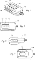
Figure 1 is a perspective view of a pressure measuring sensor according to the present invention. -
Figure 2 is a top plan view of the pressure measuring sensor shown inFigure 1 . -
Figure 3 is a side elevation view of the pressure measuring sensor shown inFigure 1 . -
Figure 4 is a bottom plan view of the pressure measuring sensor shown inFigure 1 . -
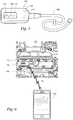
Figure 5 is a top view of a pressure measuring sensor of the present invention, coupled to a representative hose assembly and coupling. -
Figure 6 illustrates a system comprising the pressure measuring sensor coupled to and monitoring an engine, and communicating with a remote interface device. - Although the disclosure hereof is detailed and exact to enable those skilled in the art to practice the invention, the physical embodiments herein disclosed merely exemplify the invention which may be embodied in other specific structures. While the preferred embodiment has been described, the details may be changed without departing from the invention, which is defined by the claims.
- The present invention is directed to vehicle monitoring system, which can for instance be used to measure pressures in automotive/transportation applications (e.g., cylinder pressure, fuel pressure, transmission fluid pressure, and engine oil pressure) and methods for using the same.
- Referring now to
Fig. 1 , auser interface 110 is preferably provided within a device such aspressure measuring sensor 130 which preferably has adigital display 132. Thedevice 130 may be a device constructed to be primarily used to house theinterface 110 and communicate with the at least one sensor 120 (shown inFig. 5 ), having at least one of aphysical button 134 and a virtual button 136 (virtual buttons used, for instance, in a touchscreen environment) provided on thedisplay 132. The at least onephysical button 134 and/orvirtual button 136 may be configured to turn theinterface 110 on and off (i.e., a power button), to actively synchronize the at least oneremote sensor 120 and the smartphone 242 (i.e., a "sync" button), to clear the current readings (i.e., a "zero" button), and/or to select the units in which the readings will be supplied (i.e., a "units" button) . Smartphone 242 can also duplicate the readout ofinterface 110, if desired. - Additionally or alternatively, the
device 130 carries amagnet 138. Themagnet 138 is configured to retain thedevice 130 in the engine compartment (Fig. 6 ) while readings are taken (e.g., pressures are being measured), because it is contemplated that some measuring will be performed while the vehicle (the interior of which is shown inFig. 6 ) is being driven. - It is also contemplated that the
interface 110 be downloadable as an "Application" or "App" on a Smartphone 242 (Figure 6 ). Referring now to the app itself, with the power on, there is a sync button on the red unit, which then engages the phone. The phone confirms the connection. - Logs are taken, in which recorded information as readings are taken, is saved and charted. Several logs can be recorded. From a list of sequential log, we each log can be opened and analyzed by a technician, and notes can be added to each log. From the log list, the logs can be exported from the app, for instance by and email in formats such as jpg, png, csv, and provided with a summary.
- Referring to
buttons 134, in a preferred embodiment these can be for: 1) Units - to switch measurement units; 2) Mode - to switch from positive to negative (vacuum) pressure readings; 3) Cylinder - to allow a user to select how many cylinders the engine has; for instance, in a four cylinder engine, all four cylinders could be contained in one log file. In an app, or on the unit asbuttons 134 could also be a 4) Menu, to disconnect Bluetooth, or reconnect; 5) Settings, in which the unit can be set to continuous record, logging interval (how many minutes and seconds each sample should be), sound alerts, vibration alerts, and refresh rate between sampling intervals. A Record button can be set to begin a test. A Zero button can zero out the pressure reading. A Graph button can bring up a test result graphical reading in real time. This data can ultimately be saved as the log. - The
interface 110 and the at least oneremote sensor smartphone 242 and/or any other wireless technology now known or later developed. - As shown in
Figures 5 and 6 , thesystem 100 preferably comprises auser interface 110 and at least one remotepressure measuring sensor 120 carried by thedevice 130. - The
sensor 120 is preferably contained withinunit 100. This sensor is preferably fuel pressure, compression and/or vacuum, but other sensors can be carried by theunit 100 such as temperature, humidity or electrical readouts. Measurement outputs can be in psi, in/Hg, kpA, mm/hg, or bars, for instance.Unit 100 carries couplings andhose 240, for attachment to an area of inquiry in the vehicle. For instance, a fuel line, spark plug hole, or anywhere else in the vehicle of interest can receive the couplings andhose 240. A plurality ofcouplings 240 can be provided; for instance, a standard fuel setup with pressure bleed off, which can work with different fuel adaptors: Fuel injection; inline or direct port adaptors; or a Universal interchange connector. For compression, compression adaptors can be used, such as hose style, DOHC cam, or units available from Lang Tools with SKU numbers 73106, 73109, 73110 for example, each of which is incorporated by reference. - Because the
unit 100 can be carried (for instance magnetically bymagnet 138 as shown inFig. 4 ) inside the vehicle as shown inFig. 6 , the unit can transmit data tounit 242, 110 (e.g., a smart phone) while the vehicle is running and/or underway. In this manner, adual readout 132 of theunit 100 is simultaneously displayed atunit 242, and can be logged or monitored. One advantage of the present invention is the ability to remotely read measurements from an interior of the vehicle engine compartment, and record measurements on an additional device, all preferably while the vehicle is underway. - The pressure measurements taken by the at least one
remote sensor sensor 120 are preferably provided on thedisplay 132 of thedevice 130. - Synchronization of the
remote sensor 120 to theinterface 110 preferably occurs at the same rate theremote sensor 120 measures the pressures and substantially simultaneously. -
Figures 5 and 6 show aremote sensor 120 used for measuring cylinder pressure, for example. Acoupling system 240, such as a hose, couples theunit 130 with the portion of the vehicle to be analyzed, such as inFig. 6 . Thesensor 120 is coupled, by way ofcoupling system 240, for example aspark plug hole 14 in acylinder head 12 of anengine 10. The following example of thesystem 100 in use is provided as it pertains to a method for measuring cylinder pressure. It is preferable that the fuel delivery system is disengaged and the coil (not shown) is disconnected. Remove all spark plugs (not shown) from their respectivespark plug hole 14 in thecylinder head 12 and couple the remote sensor 120 (via coupling system 240) with thespark plug hole 14.Sensors smart phone 242. Theengine 10 is turned over and thepressure transducer 120 measures the pressure formed within the engine cylinder (not shown) for at least a complete intake-compression-ignition-exhaust cycle, preferably more than one complete cycle. The pressure measurements are transmitted to theinterface 242 wirelessly. It is contemplated that the cylinder pressure for the at least one intake-compression-ignition-exhaust cycle may be measured, transmitted, viewed on thedisplay 132, and recorded for each cylinder. The measured pressure values for each cylinder are preferably saved for reference by an application on thesmart phone 242. -
Sensor 120 carried byunit 130 according to the present invention can be used for measuring fuel pressure for instance. Theremote sensor 120 may be equipped to interface with a fuel system via a Schrader valve test port (not shown). - An additional
remote sensor 130 can be used for measuring transmission oil pressure, for measuring engine oil pressure, compression, vacuum and the like. - The foregoing is considered as illustrative only of the principles of the invention. Furthermore, since numerous modifications and changes will readily occur to those skilled in the art, it is not desired to limit the invention to the exact construction and operation shown and described. While the preferred embodiment has been described, the details may be changed without departing from the invention, which is defined by the claims.
Claims (5)
- A wireless testing system for measuring target operational parameters of a motor vehicle, the wireless testing system comprising:a housing, and a coupling between said housing and said motor vehicle;a sensor carried by said housing;a communicative coupling carried by said housing and coupling said sensor to a targeted operational parameter of said motor vehicle;a remote user interface wirelessly coupled to said sensor;a local user interface carried by said housing and coupled to said sensor;a control panel carried by said housing, said control panel operatively coupled with said sensor, said sensor sensing a signal from said motor vehicle comprising at least one of cylinder pressure, fuel pressure, transmission oil pressure, and engine oil pressure;said remote user interface receiving said signal.
- A wireless testing system according to claim 1, said a coupling between said housing and said motor vehicle comprising a magnetic coupling.
- A wireless testing system according to claim 1, said remote user interface comprising a mobile phone.
- A wireless testing system according to claim 1, said local user interface comprising a readout carried by said housing, and a plurality of controls comprising switches for varying at least one of settings, units, modes, and cylinders.
- A method of measuring target operational parameters of a motor vehicle, method comprising:providing a sensor sensing a signal from said motor vehicle comprising at least one of cylinder pressure, fuel pressure, transmission oil pressure, and engine oil pressure;coupling said sensor to a first interior region of said motor vehicle;transmitting readings wirelessly from said sensor to a remote user interface spaced apart from said sensor in a second interior region of said motor vehicle, physically separate from said first interior region of said motor vehicle;logging said readings with said remote user interface while said motor vehicle is in moving operation.
Applications Claiming Priority (1)
| Application Number | Priority Date | Filing Date | Title |
|---|---|---|---|
| US201662431237P | 2016-12-07 | 2016-12-07 |
Publications (1)
| Publication Number | Publication Date |
|---|---|
| EP3333809A1 true EP3333809A1 (en) | 2018-06-13 |
Family
ID=60629543
Family Applications (1)
| Application Number | Title | Priority Date | Filing Date |
|---|---|---|---|
| EP17206047.7A Pending EP3333809A1 (en) | 2016-12-07 | 2017-12-07 | Wireless pressure testing system and methods of use |
Country Status (3)
| Country | Link |
|---|---|
| US (1) | US10620076B2 (en) |
| EP (1) | EP3333809A1 (en) |
| MX (1) | MX2017015832A (en) |
Families Citing this family (2)
| Publication number | Priority date | Publication date | Assignee | Title |
|---|---|---|---|---|
| GB2563914B (en) * | 2017-06-29 | 2021-12-08 | Perkins Engines Co Ltd | Engine monitoring |
| BE1027195B1 (en) * | 2019-04-17 | 2020-11-19 | Hubitools SA | PRESSURE MEASURING DEVICE |
Citations (3)
| Publication number | Priority date | Publication date | Assignee | Title |
|---|---|---|---|---|
| US20050150282A1 (en) * | 2004-01-12 | 2005-07-14 | Keith Andreasen | Digital compression gauge |
| US20120109544A1 (en) * | 2010-10-29 | 2012-05-03 | Spx Corporation | Digital compression recorder with specification database system and method |
| US20140350752A1 (en) * | 2011-03-11 | 2014-11-27 | Intelligent Agricultural Solutions, Llc | Method and system for managing the hand-off between control terminals |
Family Cites Families (16)
| Publication number | Priority date | Publication date | Assignee | Title |
|---|---|---|---|---|
| DE4419189A1 (en) | 1994-06-01 | 1995-12-07 | Bosch Gmbh Robert | Device for diagnosing motor vehicles |
| US5884202A (en) | 1995-07-20 | 1999-03-16 | Hewlett-Packard Company | Modular wireless diagnostic test and information system |
| US6029508A (en) | 1996-03-25 | 2000-02-29 | Snap-On Technologies, Inc. | Remote portable display unit with wireless transceiver and engine analyzing system incorporating same |
| US5875413A (en) | 1996-05-17 | 1999-02-23 | Waekon Corporation | Digital remote gauge assembly |
| US5663493A (en) | 1996-05-17 | 1997-09-02 | Fluke Corporation | Apparatus and method for measuring relative compression |
| USD390140S (en) | 1997-01-21 | 1998-02-03 | Measurement Specialties, Inc. | Tire pressure gauge |
| US20020134150A1 (en) | 2001-03-22 | 2002-09-26 | Shih-Pin Shih | Automatic car tire pressure detecting apparatus |
| US6701232B2 (en) | 2001-04-25 | 2004-03-02 | Fuji Jukogyo Kabushiki Kaisha | Vehicle management system |
| AT8411U3 (en) | 2006-03-02 | 2007-03-15 | Avl List Gmbh | TEST BENCH SENSOR DEVICE, AND TEST BENCH, PREFERABLY FOR POWER MACHINES |
| US8710796B2 (en) * | 2009-07-28 | 2014-04-29 | Bosch Automotive Service Solutions Llc | Electric vehicle supply equipment having a socket and a method of charging an electric vehicle |
| USD648236S1 (en) | 2010-08-12 | 2011-11-08 | Measurement Ltd. | Combination tire pressure and tread depth gauge |
| USD683643S1 (en) | 2011-10-31 | 2013-06-04 | Measurement, Ltd. | Combination tire pressure and tread depth gauge |
| USD671023S1 (en) | 2011-10-31 | 2012-11-20 | Measurement Ltd. | Combination tire pressure and tread depth gauge |
| USD700089S1 (en) | 2012-12-18 | 2014-02-25 | Gregory S. Sundheim | Pressure gauge |
| US9188505B2 (en) | 2013-06-21 | 2015-11-17 | Ford Global Technologies, Llc | Method and system for cylinder compression diagnostics |
| CA3186396A1 (en) * | 2014-01-20 | 2015-07-23 | Parker-Hannifin Corporation | Hose free sensor system for refrigerant unit |
-
2017
- 2017-12-05 US US15/832,357 patent/US10620076B2/en active Active
- 2017-12-06 MX MX2017015832A patent/MX2017015832A/en unknown
- 2017-12-07 EP EP17206047.7A patent/EP3333809A1/en active Pending
Patent Citations (3)
| Publication number | Priority date | Publication date | Assignee | Title |
|---|---|---|---|---|
| US20050150282A1 (en) * | 2004-01-12 | 2005-07-14 | Keith Andreasen | Digital compression gauge |
| US20120109544A1 (en) * | 2010-10-29 | 2012-05-03 | Spx Corporation | Digital compression recorder with specification database system and method |
| US20140350752A1 (en) * | 2011-03-11 | 2014-11-27 | Intelligent Agricultural Solutions, Llc | Method and system for managing the hand-off between control terminals |
Also Published As
| Publication number | Publication date |
|---|---|
| US10620076B2 (en) | 2020-04-14 |
| MX2017015832A (en) | 2018-11-09 |
| US20180156685A1 (en) | 2018-06-07 |
Similar Documents
| Publication | Publication Date | Title |
|---|---|---|
| CN203053490U (en) | Pressure difference transmitter with redundancy sensor | |
| US10620076B2 (en) | Wireless pressure testing system and methods of use | |
| US9419392B2 (en) | Automatic identification of an adapter in an on-board diagnostic system | |
| JP5559365B2 (en) | Process variable transmitter with display | |
| EP2972146B1 (en) | Vibration analyzer for vehicle diagnostics | |
| EP2309769A2 (en) | Wireless data logging device | |
| WO2006050380A3 (en) | Programmable automotive computer system | |
| US20110083521A1 (en) | Wireless circular chart recorder | |
| US20060195043A1 (en) | Methods and apparatus for measuring pressures in bodily fluids | |
| US9470597B2 (en) | Wireless interface for a plurality of transducers | |
| CN106471193B (en) | Pressure sensor apparatus for common network | |
| US5602337A (en) | Abnormal sound detecting apparatus | |
| CN105556239B (en) | Connector with driving side connection part and slave end connection part | |
| JP2007286054A (en) | Filter seating monitor | |
| US20130297225A1 (en) | Modular system and methodology for testing and measurement | |
| US20190058979A1 (en) | Remote diagnostic system | |
| CN104180990B (en) | The release travel method of testing of clutch release bearing structure and clutch | |
| US20170192405A1 (en) | Condition monitoring device and monitoring system using the same | |
| US11815364B2 (en) | Environmental condition sensor with component diagnostics and optically communicated status | |
| CN202372206U (en) | Airspeed pressure altitude checking device for unmanned aerial vehicle | |
| US20220301366A1 (en) | Pressure testing system and data logger | |
| CN211178575U (en) | Multi-space internal environment remote detection device | |
| KR20040100446A (en) | Smart Sensor using Bluetooth Technology | |
| CN210536951U (en) | Intelligent reading instrument | |
| US20170097249A1 (en) | Sensor and cable with local wireless read and write capability and methods of using same |
Legal Events
| Date | Code | Title | Description |
|---|---|---|---|
| PUAI | Public reference made under article 153(3) epc to a published international application that has entered the european phase |
Free format text: ORIGINAL CODE: 0009012 |
|
| STAA | Information on the status of an ep patent application or granted ep patent |
Free format text: STATUS: THE APPLICATION HAS BEEN PUBLISHED |
|
| AK | Designated contracting states |
Kind code of ref document: A1 Designated state(s): AL AT BE BG CH CY CZ DE DK EE ES FI FR GB GR HR HU IE IS IT LI LT LU LV MC MK MT NL NO PL PT RO RS SE SI SK SM TR |
|
| AX | Request for extension of the european patent |
Extension state: BA ME |
|
| STAA | Information on the status of an ep patent application or granted ep patent |
Free format text: STATUS: REQUEST FOR EXAMINATION WAS MADE |
|
| 17P | Request for examination filed |
Effective date: 20181204 |
|
| RAX | Requested extension states of the european patent have changed |
Extension state: ME Payment date: 20181204 Extension state: BA Payment date: 20181204 |
|
| RBV | Designated contracting states (corrected) |
Designated state(s): AL AT BE BG CH CY CZ DE DK EE ES FI FR GB GR HR HU IE IS IT LI LT LU LV MC MK MT NL NO PL PT RO RS SE SI SK SM TR |
|
| STAA | Information on the status of an ep patent application or granted ep patent |
Free format text: STATUS: REQUEST FOR EXAMINATION WAS MADE |
|
| STAA | Information on the status of an ep patent application or granted ep patent |
Free format text: STATUS: EXAMINATION IS IN PROGRESS |
|
| 17Q | First examination report despatched |
Effective date: 20210618 |
|
| STAA | Information on the status of an ep patent application or granted ep patent |
Free format text: STATUS: EXAMINATION IS IN PROGRESS |
|
| P01 | Opt-out of the competence of the unified patent court (upc) registered |
Effective date: 20230718 |