EP2972146B1 - Vibration analyzer for vehicle diagnostics - Google Patents
Vibration analyzer for vehicle diagnostics Download PDFInfo
- Publication number
- EP2972146B1 EP2972146B1 EP14763407.5A EP14763407A EP2972146B1 EP 2972146 B1 EP2972146 B1 EP 2972146B1 EP 14763407 A EP14763407 A EP 14763407A EP 2972146 B1 EP2972146 B1 EP 2972146B1
- Authority
- EP
- European Patent Office
- Prior art keywords
- vibration
- analyzer
- vehicle
- vibration analyzer
- data
- Prior art date
- Legal status (The legal status is an assumption and is not a legal conclusion. Google has not performed a legal analysis and makes no representation as to the accuracy of the status listed.)
- Active
Links
- 238000000034 method Methods 0.000 claims description 10
- 238000012360 testing method Methods 0.000 claims description 10
- 238000001514 detection method Methods 0.000 claims description 3
- 230000006870 function Effects 0.000 claims description 3
- 238000007493 shaping process Methods 0.000 claims 1
- 238000004891 communication Methods 0.000 description 11
- 238000004458 analytical method Methods 0.000 description 4
- 238000010586 diagram Methods 0.000 description 4
- 239000000853 adhesive Substances 0.000 description 3
- 230000001070 adhesive effect Effects 0.000 description 3
- 239000003292 glue Substances 0.000 description 3
- -1 Nickel Metal Hydride Chemical class 0.000 description 2
- 238000010276 construction Methods 0.000 description 2
- 230000001419 dependent effect Effects 0.000 description 2
- 238000003745 diagnosis Methods 0.000 description 2
- 239000000463 material Substances 0.000 description 2
- 229910052759 nickel Inorganic materials 0.000 description 2
- PXHVJJICTQNCMI-UHFFFAOYSA-N nickel Substances [Ni] PXHVJJICTQNCMI-UHFFFAOYSA-N 0.000 description 2
- WHXSMMKQMYFTQS-UHFFFAOYSA-N Lithium Chemical compound [Li] WHXSMMKQMYFTQS-UHFFFAOYSA-N 0.000 description 1
- HBBGRARXTFLTSG-UHFFFAOYSA-N Lithium ion Chemical compound [Li+] HBBGRARXTFLTSG-UHFFFAOYSA-N 0.000 description 1
- 230000001133 acceleration Effects 0.000 description 1
- 238000003491 array Methods 0.000 description 1
- OJIJEKBXJYRIBZ-UHFFFAOYSA-N cadmium nickel Chemical compound [Ni].[Cd] OJIJEKBXJYRIBZ-UHFFFAOYSA-N 0.000 description 1
- 230000001413 cellular effect Effects 0.000 description 1
- 230000008878 coupling Effects 0.000 description 1
- 238000010168 coupling process Methods 0.000 description 1
- 238000005859 coupling reaction Methods 0.000 description 1
- 238000007405 data analysis Methods 0.000 description 1
- 230000007423 decrease Effects 0.000 description 1
- 238000011156 evaluation Methods 0.000 description 1
- 239000011888 foil Substances 0.000 description 1
- 229910052739 hydrogen Inorganic materials 0.000 description 1
- 239000001257 hydrogen Substances 0.000 description 1
- 229910052744 lithium Inorganic materials 0.000 description 1
- 229910001416 lithium ion Inorganic materials 0.000 description 1
- 229910052987 metal hydride Inorganic materials 0.000 description 1
- 238000012544 monitoring process Methods 0.000 description 1
- 229920000642 polymer Polymers 0.000 description 1
- 230000002028 premature Effects 0.000 description 1
- 230000008439 repair process Effects 0.000 description 1
- 230000035945 sensitivity Effects 0.000 description 1
- 230000035939 shock Effects 0.000 description 1
- 229920001169 thermoplastic Polymers 0.000 description 1
- 239000004416 thermosoftening plastic Substances 0.000 description 1
- 238000012795 verification Methods 0.000 description 1
Images

Classifications
-
- G—PHYSICS
- G01—MEASURING; TESTING
- G01M—TESTING STATIC OR DYNAMIC BALANCE OF MACHINES OR STRUCTURES; TESTING OF STRUCTURES OR APPARATUS, NOT OTHERWISE PROVIDED FOR
- G01M7/00—Vibration-testing of structures; Shock-testing of structures
-
- G—PHYSICS
- G07—CHECKING-DEVICES
- G07C—TIME OR ATTENDANCE REGISTERS; REGISTERING OR INDICATING THE WORKING OF MACHINES; GENERATING RANDOM NUMBERS; VOTING OR LOTTERY APPARATUS; ARRANGEMENTS, SYSTEMS OR APPARATUS FOR CHECKING NOT PROVIDED FOR ELSEWHERE
- G07C5/00—Registering or indicating the working of vehicles
- G07C5/008—Registering or indicating the working of vehicles communicating information to a remotely located station
-
- G—PHYSICS
- G01—MEASURING; TESTING
- G01H—MEASUREMENT OF MECHANICAL VIBRATIONS OR ULTRASONIC, SONIC OR INFRASONIC WAVES
- G01H1/00—Measuring characteristics of vibrations in solids by using direct conduction to the detector
Definitions
- the present invention relates generally to a vibration-sensing device. More particularly, the present invention relates to a vehicle vibration sensor that is incorporated in a vibration analyzer.
- Modern vehicles include components that are subjected to torsional vibration when the vehicle is driven or while operating.
- the torsional vibration can cause premature damage to the components or cause unwanted noise in the vehicle.
- the source of the torsional vibration can be detected with a vibration analyzer.
- the conventional vibration analyzer can include an external sensor or multiple sensors located in various parts of the vehicle.
- the sensor's signal can be received by a channel or multi-channel vibration analyzer.
- conventional vibration sensors do not include a self-contained battery or wireless communication or network capabilities in order to pool various data points.
- the conventional vibration analyzer requires mounting of the vibration sensor on the plane of measured vibration axis as most of the vibration sensors operate only on one axis plane.
- vehicle parameters that can be obtained from an electronic control unit of a vehicle, such as vehicle speed, engine rotations per minute are also necessary part of the vibration testing or analysis.
- D1 discloses a way to obtain a structural monitoring information from a large number of sensors that can be deployed in arrays to provide information over wide areas of a structure. For example sensors can be placed at different positions on the vehicle and the sensors can communicate over a wired or over a wireless network. The network is scalable, meaning a large number of sensor nodes can be included in the network. Further, D1 also discloses that one could also use the difference (rather than the ratio mentioned above) between strain amplitudes as measured by some piezoelectric and foil gauges as a built in self test (BIST). Ideally, a dynamic calibration procedure could be used to allow PZT amplitudes to be expressed in units of microstrain. This would require a calibration procedure, which could be done at the factory prior to delivery to the customer, in order to document the sensitivity of the PZT to applied dynamic strains. There are no further details, however, on the actual calibration test.
- Document D3 and document D7 respectively relate to other systems and methods for analysing vibrations.
- document D3 discloses a vehicle vibration analyser which receives vibration data and vehicle data and analyses them in order to determine a source of the vibration.
- Document D2 describes a method for detecting and analyzing vibrations in a vehicle, including a vibration analyzer in which a three-axis accelerometer, a controller, a memory and a network interface are located in the same device.
- Document D8 describes a system in which two sensors are used to detect the same value, in order to verify the correct functioning of the system, based on the discrepancy between two measures.
- the object of the present invention is to provide a testing system and method which can provide an improved evaluation of vibration data occurring in a vehicle component. This object is solved by a system according to claim 1 and by a method according to claim 5. Further advantageous embodiments and improvements of the invention are listed in the dependent claims.
- One aspect of the invention relates to a system for detecting and analyzing a vibration of a vehicle component, according to claim 1.
- a method of detecting a vibration of a vehicle component is provided, according to claim 5.
- An aspect in accordance with the present invention provides an apparatus, such as a vehicle vibration analyzer that includes an accelerometer/vibration sensor, a host interface microcontroller, and a wired and/or wireless connection.
- vehicle vibration analyzer that includes an accelerometer/vibration sensor, a host interface microcontroller, and a wired and/or wireless connection.
- the types of vehicle that the vibration analyzer can be used on include automobiles, trains, planes, and ships.
- FIGS. 1A-C are side views illustrating vibration analyzers according to various embodiments of the invention.
- the housing of the vibration analyzer can be made from a shape forming material, such as a polymer, thermoplastic and the like, or be malleable so that the housing can be shaped according to the need of the user. For example, if the vibration analyzer is placed on a rounded surface, such as a conduit, then the vibration analyzer housing can be bent to fit around the conduit.
- the housing can be configured to not affect the functionality of the internal components of the vibration analyzer, such as having enough space between where the components are located and an external surface of the housing.
- FIG. 1A illustrates a side view of a generally rectangular vibration analyzer 100A.
- a housing 102 can be formed into any shape and in this embodiment, it may be formed into a generally rectangular shape.
- the general rectangular shaped of the vibration analyzer 100A allows it to be placed on a generally flat surface of a portion of a vehicle.
- the vibration analyzer 100A is constructed and configured to be heavy or weighted down enough to properly detect vibration of the portion of the vehicle or a component of the vehicle being tested.
- the vibration analyzer 100A can be coupled to the portion of the vehicle or the component using adhesives, magnets, straps, Velcro, nonpermanent glue, and the like.
- the coupling can be permanent or temporary. By being permanent, the particular component can be tested over a long period of time, such as for prototyping purposes.
- the vibration analyzer 100A also includes an interface port 104 to interface with various connectors such as USB, FireWire, serial, parallel, RS 232, RS485, OBD (I and II), Ethernet, and the like.
- Interface port 104 allows for communication between vibration analyzer 100A and another device, such as a computer device.
- interface port 104 allows for communication and/or power with the computing device.
- the communication and/or power can be bi-directional.
- the computing device can include a diagnostic tool, a remote computer or another vibration analyzer.
- Other devices may include a storage device, such as a hard drive, USB drive, CD player, DVD player, UMD player or other computer readable medium devices.
- FIG. 1B illustrates a side view of a generally triangular vibration analyzer 100B.
- the housing 102 can be formed into any shape and in this embodiment, it may be formed into a generally triangular shape.
- the general triangular shaped of the vibration analyzer 100B allows it to be placed on a generally flat surface of a portion of a vehicle or a crevice or hole in the vehicle. Because vibration analyzer 100B includes a pointed end, it may be placed with the pointed end in a crevice or a hole of a portion of the vehicle and thereby, held within the hole during use.
- the vibration analyzer 100B is also constructed and configured to be heavy or weighted down enough to properly detect vibration of the portion of the vehicle or a component of the vehicle being tested.
- the vibration analyzer 100A can be coupled (temporarily or permanently) to the portion of the vehicle or the component using adhesives, straps, magnets, Velcro, nonpermanent glue, and the like.
- the vibration analyzer 100B can also include an interface port 104 to interface with various connectors such as USB, FireWire, serial, parallel, RS 232, RS485, OBD (I and II), Ethernet, and the like.
- Interface port 104 allows for communication between vibration analyzer 100B and another device, such as a computer device.
- FIG. 1C illustrates a side view of a generally half circular vibration analyzer 100C.
- the housing 102 can be formed into any shape and in this embodiment, it may be formed into a generally half circular shape.
- the general half circular shaped of the vibration analyzer 100C allows it to be placed on a generally circular surface of a portion of a vehicle, such as a hose, a pipe, a shock and the like.
- the vibration analyzer 100C is also constructed and configured to be heavy or weighted down enough to properly detect vibration of the portion of the vehicle or a component of the vehicle being tested.
- the vibration analyzer 100C can be coupled (temporarily or permanently) to the portion of the vehicle or the component using adhesives, straps, magnets, Velcro, nonpermanent glue, and the like.
- the vibration analyzer 100C can also include an interface port 104 to interface with various connectors such as USB, FireWire, serial, parallel, RS 232, RS485, OBD (I and II), Ethernet, and the like.
- Interface port 104 allows for communication between vibration analyzer 100C and another device, such as a computer device.
- the vibration analyzer may be configured to partially or totally wrap around any object that it is placed with. By be able to be partially or totally wrapped around the object, the vibration analyzer can be placed on or around any shaped objects including oddly shaped objects so that potentially any vibration in the vehicle can be detected and determined. Additionally, by being able to be partially or totally wrapped around any object, the vibration analyzer can be held in place better than simply being placed on the object.
- the housing 102 may also be made from a material that can withstand the harsh environments that it may be placed in, such as a vehicle.
- the housing can be configured to protect the components of the vibration analyzer 100A-C described herein.
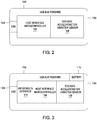
- FIG. 2 is a block diagram of the components of the vibration analyzer 100A-C according to an embodiment of the invention.
- the vibration analyzer 100A-C includes the housing 102, the interface port 104 in the form of a USB connector, a host interface microcontroller 106 and a 1/2/3 axis accelerometer/vibration sensor 108.
- the housing 102 can be the shaped into any shape desired by the user.
- the host interface microcontroller 106 can control the operations of the vibration analyzer 100A-C and includes software to operate the vibration analyzer and to communicate with another device, such as a scan tool or a computing device.
- the host interface microcontroller 106 includes a memory (not shown) to store the software and any data received by the vibration analyzer 100A-C. Further, depending on the type of sensor 108 used, the host interface microcontroller 106 may include an analog to digital converter.
- the host interface microcontroller 106 can also calculate and format the data received from the sensor and/or the vehicle data from the electronic control unit in the vehicle. The formatted data can then be sent to another device in the format useable for that device.
- the 1/2/3 axis accelerometer/vibration sensor 108 allows detection of the vibration in all three axis (x-y-z).
- the sensor 108 may include a MEMS accelerometer. By detecting in all three axis, the vibration analyzer 100A-C can detect the vibration in any direction and is not necessarily dependent on the correct directional detection placement in order to function properly. That is the vibration analyzer 100A-C does not have to be placed or mounted on the plane of the measured vibration axis.
- the 1/2/3 axis accelerometer/vibration sensor 108 can communicate with and be controlled by the host interface microcontroller 106.
- the interface port 104 may be a USB port that allows communication with another device. Additionally, the interface port 104 allows for power that is available from another device to power the vibration analyzer 100A-C. The interface port 104 also allows for the vibration analyzer 100A-C to be networked with another device, such as a scan tool, computing device or even another vibration analyzer. Additionally, the interface port 104 allows for another device to program or reprogram the vibration analyzer 100A-C. Some programming may include when to send the measured acceleration data (when above a certain threshold), transmitting frequency (to match receiver frequency), formatting, data analysis, and the like.
- FIG. 3 is a block diagram of the components of the vibration analyzer 100A-C according to another embodiment of the invention.
- the vibration analyzer 100A-C includes the housing 102, the interface port 104 in the form of a USB connector, the host interface microcontroller 106 and a 1/2/3 axis accelerometer/vibration sensor 108, a wireless interface 110 and a battery 112.
- the components of FIG. 3 are similar to the components of FIG. 2 except for the addition of the wireless interface 110 and battery 112.
- the wireless interface 110 allows for wireless communication with another device and allows the vibration analyzer 100A-C to be networked with a computing device or another vibration analyzer.
- the wireless interface 110 may communicate in various protocols, such as RF (radio frequency), satellites, cellular phones (analog or digital), Bluetooth®, Wi-Fi, 802.15, Infrared, Zigby, near field communication, Local Area Networks (LAN), WLAN (Wireless Local Area Network), or other wireless communication configurations and standards.
- the wireless interface 110 may be controlled by the host interface microcontroller 106 and provide information (analyzed data) to and from another device.
- the wireless interface 110 may also receive wirelessly vehicle data from a scan tool or a vehicle communication interface that is coupled to the vehicle OBD (I or II) port.
- the wireless interface 110 may also be part of the components of the vibration analyzer 100A-C shown in FIG. 2 .
- the vibration analyzer 100A-C receives vehicle data from the vehicle's ECU (electronic control unit) through the interface port 104 or through the wireless interface 110.
- the interface port 104 may be any type of connector including a connector for a cable that couples with an OBD (I or II) port in the vehicle.
- the vehicle data such as engine rpm or vehicle speed, is received by the host interface microcontroller 106.
- the vehicle data may also be packaged with the vibration data received from the 1/2/3 axis accelerometer/vibration sensor 108.
- the host interface microcontroller 106 analyzes the vibration data and the vehicle data using conventional analysis software packages and determine the source of the vibration.
- the host interface microcontroller 106 can determine if the vibration meets or surpasses a certain threshold and that it is at a level that requires replacement or repair of the vehicle component. The analyzed data can then be formatted to a format useable by another device and transmitted to another device.
- the battery 112 can be used to power the components of vibration analyzer 100A-C.
- the battery 112 may be Nickel Cadmium, Nickel Metal Hydride, and Lithium Ion, Lithium air, Nickel Hydrogen, and the like.
- the battery may be integrated or replaceable, or rechargeable, as needed.
- the interface port 104 can be used to charge the battery 112 via an external power source.
- the battery 112 can be part of the components described in FIG. 2 .
- the ability to network the vibration analyzer 100A-C with each other and to the scan tool or other computing device allows for the deployment of more than one vibration analyzer 100A-C throughout the vehicle. This allows for faster analysis and quicker location of the vibration. Additionally, the vibration analyzer 100A-C may be programed to forward to another device only data related to vibration that meets certain threshold characteristics. This decreases the amount of false vibration signals produced during testing and allows for quicker diagnosis.
- the self-test of the vibration analyzer 100A-C occurs through the use of the network. Two or more vibration analyzers 100A-C are placed on the same portion of the vehicle, for example an axle or a pipe, and should provide similar signals to a computing device for independent verification. If the signals are similar (within certain frequency, for example) then the vibration analyzers 100A-C are working properly. If the signals are different from each other (by a predetermined range) then one of the vibration analyzers 100A-C is not functioning properly and may need to be calibrated or fixed. This self-test allows the technician to be confident in the data received from the vibration analyzer 100A-C and confident in his diagnosis.
- the embodiments herein include the vibration sensor being integrated in the vibration analyzer. This allows for the sensing and analysis of the vibration data along with the vehicle data in one device.
Description
- The present invention relates generally to a vibration-sensing device. More particularly, the present invention relates to a vehicle vibration sensor that is incorporated in a vibration analyzer.
- Modern vehicles include components that are subjected to torsional vibration when the vehicle is driven or while operating. The torsional vibration can cause premature damage to the components or cause unwanted noise in the vehicle. The source of the torsional vibration can be detected with a vibration analyzer.
- The conventional vibration analyzer can include an external sensor or multiple sensors located in various parts of the vehicle. The sensor's signal can be received by a channel or multi-channel vibration analyzer. Additionally, conventional vibration sensors do not include a self-contained battery or wireless communication or network capabilities in order to pool various data points. Further, the conventional vibration analyzer requires mounting of the vibration sensor on the plane of measured vibration axis as most of the vibration sensors operate only on one axis plane. Additionally, vehicle parameters that can be obtained from an electronic control unit of a vehicle, such as vehicle speed, engine rotations per minute are also necessary part of the vibration testing or analysis.
- Accordingly, it is desirable to provide a vibration analyzer that can be easily deployed and include network connectability.
- The following references denoted as D1, D2, D3, D7 and D8 disclose further technological background art for the present invention:
- D1
-
US 2008/036617 A1 (ARMS STEVEN W [US] ET AL) 14 February 2008 (2008-02-14 - D2
-
WO 2009/068983 A2 (GARIGLIO, CLAUDIO ET AL.) 4 June 2009 (2009-06-04 - D3
-
US 2003/088346 A1 (THOMAS R. CALKINS ET AL.) 8 May 2003 (2003-05-08 - D7
-
DE 41 34 902 A1 (MITSUBISHI ELECTRIC CORP [JP]) 4 June 1992 (1992-06-04) - D8
-
DE 102 42 128 A1 (BOSCH GMBH ROBERT [DE]) 25 March 2004 (2004-03-25 ) - D1 discloses a way to obtain a structural monitoring information from a large number of sensors that can be deployed in arrays to provide information over wide areas of a structure. For example sensors can be placed at different positions on the vehicle and the sensors can communicate over a wired or over a wireless network. The network is scalable, meaning a large number of sensor nodes can be included in the network. Further, D1 also discloses that one could also use the difference (rather than the ratio mentioned above) between strain amplitudes as measured by some piezoelectric and foil gauges as a built in self test (BIST). Ideally, a dynamic calibration procedure could be used to allow PZT amplitudes to be expressed in units of microstrain. This would require a calibration procedure, which could be done at the factory prior to delivery to the customer, in order to document the sensitivity of the PZT to applied dynamic strains. There are no further details, however, on the actual calibration test.
- Document D3 and document D7 respectively relate to other systems and methods for analysing vibrations. In particular, document D3 discloses a vehicle vibration analyser which receives vibration data and vehicle data and analyses them in order to determine a source of the vibration. Document D2 describes a method for detecting and analyzing vibrations in a vehicle, including a vibration analyzer in which a three-axis accelerometer, a controller, a memory and a network interface are located in the same device. Document D8 describes a system in which two sensors are used to detect the same value, in order to verify the correct functioning of the system, based on the discrepancy between two measures.
- The object of the present invention is to provide a testing system and method which can provide an improved evaluation of vibration data occurring in a vehicle component. This object is solved by a system according to claim 1 and by a method according to claim 5. Further advantageous embodiments and improvements of the invention are listed in the dependent claims. Hereinafter, before coming to the detailed discussion of the embodiments of the invention with reference to the attached drawings, some aspects which contribute to the understanding of the invention but do not directly relate to the invention are discussed below separately.
- One aspect of the invention relates to a system for detecting and analyzing a vibration of a vehicle component, according to claim 1.
- In accordance with yet another aspect of the present invention, a method of detecting a vibration of a vehicle component is provided, according to claim 5.
- There has thus been outlined, rather broadly, certain aspects of the invention in order that the detailed description herein may be better understood, and in order that the present contribution to the art may be better appreciated. There are, of course, additional aspects and examples as well as embodiments of the invention that will be described below and which will form the subject matter of the claims appended hereto.
- In this respect, before explaining at least one embodiment of the invention in detail, it is to be understood that the invention is not limited in its application to the details of construction and to the arrangements of the components set forth in the following description or illustrated in the drawings. The invention is capable of embodiments in addition to those described and of being practiced and carried out in various ways. Also, it is to be understood that the phraseology and terminology employed herein, as well as the abstract, are for the purpose of description and should not be regarded as limiting.
- As such, those skilled in the art will appreciate that the conception upon which this disclosure is based may readily be utilized as a basis for the designing of other structures, methods and systems for carrying out the several purposes of the present invention. It is important, therefore, that the claims be regarded as including such equivalent constructions insofar as they do not depart from the scope of the present invention, as defined in the appended claims.
-
-
FIGS. 1A-C is side views illustrating vibration analyzers according to various embodiments of the invention. -
FIG. 2 is a block diagram of the components of the vibration analyzer according to an embodiment of the invention. -
FIG. 3 illustrates a block diagram of the components of the vibration analyzer according to another embodiment of the invention. - The invention will now be described with reference to the drawing figures, in which like reference numerals refer to like parts throughout. An aspect in accordance with the present invention provides an apparatus, such as a vehicle vibration analyzer that includes an accelerometer/vibration sensor, a host interface microcontroller, and a wired and/or wireless connection. The types of vehicle that the vibration analyzer can be used on include automobiles, trains, planes, and ships.
- Although in the present specification embodiments are referred to throughout the entire description, it should be noted that the embodiment relating to claim 1 and claim 5 is described in the portion of paragraph [0031] to and including paragraph [0034] whilst the other "embodiments" should be understood as "examples" which do not directly relate to the invention as claimed, but which contain further aspects which are usable with the invention and contribute to an understanding of the invention.
- Embodiments of the present inventive apparatuses are illustrated in
FIGS. 1A-C . In particular,FIGS. 1A-C are side views illustrating vibration analyzers according to various embodiments of the invention. These various embodiments for vibration analyzers allow the user the flexibility of using the proper (including proper shaped) vibration analyzer based on the shape of the component where the analyzer is placed. In one embodiment, the housing of the vibration analyzer can be made from a shape forming material, such as a polymer, thermoplastic and the like, or be malleable so that the housing can be shaped according to the need of the user. For example, if the vibration analyzer is placed on a rounded surface, such as a conduit, then the vibration analyzer housing can be bent to fit around the conduit. The housing can be configured to not affect the functionality of the internal components of the vibration analyzer, such as having enough space between where the components are located and an external surface of the housing. -
FIG. 1A illustrates a side view of a generallyrectangular vibration analyzer 100A. Ahousing 102 can be formed into any shape and in this embodiment, it may be formed into a generally rectangular shape. The general rectangular shaped of thevibration analyzer 100A allows it to be placed on a generally flat surface of a portion of a vehicle. Thevibration analyzer 100A is constructed and configured to be heavy or weighted down enough to properly detect vibration of the portion of the vehicle or a component of the vehicle being tested. In another embodiment, thevibration analyzer 100A can be coupled to the portion of the vehicle or the component using adhesives, magnets, straps, Velcro, nonpermanent glue, and the like. The coupling can be permanent or temporary. By being permanent, the particular component can be tested over a long period of time, such as for prototyping purposes. - The
vibration analyzer 100A also includes aninterface port 104 to interface with various connectors such as USB, FireWire, serial, parallel, RS 232, RS485, OBD (I and II), Ethernet, and the like.Interface port 104 allows for communication betweenvibration analyzer 100A and another device, such as a computer device. In another embodiment,interface port 104 allows for communication and/or power with the computing device. The communication and/or power can be bi-directional. The computing device can include a diagnostic tool, a remote computer or another vibration analyzer. Other devices may include a storage device, such as a hard drive, USB drive, CD player, DVD player, UMD player or other computer readable medium devices. -
FIG. 1B illustrates a side view of a generallytriangular vibration analyzer 100B. Thehousing 102 can be formed into any shape and in this embodiment, it may be formed into a generally triangular shape. The general triangular shaped of thevibration analyzer 100B allows it to be placed on a generally flat surface of a portion of a vehicle or a crevice or hole in the vehicle. Becausevibration analyzer 100B includes a pointed end, it may be placed with the pointed end in a crevice or a hole of a portion of the vehicle and thereby, held within the hole during use. Thevibration analyzer 100B is also constructed and configured to be heavy or weighted down enough to properly detect vibration of the portion of the vehicle or a component of the vehicle being tested. In another embodiment, thevibration analyzer 100A can be coupled (temporarily or permanently) to the portion of the vehicle or the component using adhesives, straps, magnets, Velcro, nonpermanent glue, and the like. - Like
vibration analyzer 100A, thevibration analyzer 100B can also include aninterface port 104 to interface with various connectors such as USB, FireWire, serial, parallel, RS 232, RS485, OBD (I and II), Ethernet, and the like.Interface port 104 allows for communication betweenvibration analyzer 100B and another device, such as a computer device. -
FIG. 1C illustrates a side view of a generally halfcircular vibration analyzer 100C. Thehousing 102 can be formed into any shape and in this embodiment, it may be formed into a generally half circular shape. The general half circular shaped of thevibration analyzer 100C allows it to be placed on a generally circular surface of a portion of a vehicle, such as a hose, a pipe, a shock and the like. Thevibration analyzer 100C is also constructed and configured to be heavy or weighted down enough to properly detect vibration of the portion of the vehicle or a component of the vehicle being tested. In another embodiment, thevibration analyzer 100C can be coupled (temporarily or permanently) to the portion of the vehicle or the component using adhesives, straps, magnets, Velcro, nonpermanent glue, and the like. - The
vibration analyzer 100C can also include aninterface port 104 to interface with various connectors such as USB, FireWire, serial, parallel, RS 232, RS485, OBD (I and II), Ethernet, and the like.Interface port 104 allows for communication betweenvibration analyzer 100C and another device, such as a computer device. - In still another embodiment, the vibration analyzer may be configured to partially or totally wrap around any object that it is placed with. By be able to be partially or totally wrapped around the object, the vibration analyzer can be placed on or around any shaped objects including oddly shaped objects so that potentially any vibration in the vehicle can be detected and determined. Additionally, by being able to be partially or totally wrapped around any object, the vibration analyzer can be held in place better than simply being placed on the object.
- The
housing 102 may also be made from a material that can withstand the harsh environments that it may be placed in, such as a vehicle. The housing can be configured to protect the components of thevibration analyzer 100A-C described herein. -
FIG. 2 is a block diagram of the components of thevibration analyzer 100A-C according to an embodiment of the invention. Thevibration analyzer 100A-C includes thehousing 102, theinterface port 104 in the form of a USB connector, ahost interface microcontroller 106 and a 1/2/3 axis accelerometer/vibration sensor 108. - As previously stated, the
housing 102 can be the shaped into any shape desired by the user. Thehost interface microcontroller 106 can control the operations of thevibration analyzer 100A-C and includes software to operate the vibration analyzer and to communicate with another device, such as a scan tool or a computing device. Thehost interface microcontroller 106 includes a memory (not shown) to store the software and any data received by thevibration analyzer 100A-C. Further, depending on the type ofsensor 108 used, thehost interface microcontroller 106 may include an analog to digital converter. Thehost interface microcontroller 106 can also calculate and format the data received from the sensor and/or the vehicle data from the electronic control unit in the vehicle. The formatted data can then be sent to another device in the format useable for that device. - The 1/2/3 axis accelerometer/
vibration sensor 108 allows detection of the vibration in all three axis (x-y-z). Thesensor 108 may include a MEMS accelerometer. By detecting in all three axis, thevibration analyzer 100A-C can detect the vibration in any direction and is not necessarily dependent on the correct directional detection placement in order to function properly. That is thevibration analyzer 100A-C does not have to be placed or mounted on the plane of the measured vibration axis. The 1/2/3 axis accelerometer/vibration sensor 108 can communicate with and be controlled by thehost interface microcontroller 106. - The
interface port 104, in one embodiment, may be a USB port that allows communication with another device. Additionally, theinterface port 104 allows for power that is available from another device to power thevibration analyzer 100A-C. Theinterface port 104 also allows for thevibration analyzer 100A-C to be networked with another device, such as a scan tool, computing device or even another vibration analyzer. Additionally, theinterface port 104 allows for another device to program or reprogram thevibration analyzer 100A-C. Some programming may include when to send the measured acceleration data (when above a certain threshold), transmitting frequency (to match receiver frequency), formatting, data analysis, and the like. -
FIG. 3 is a block diagram of the components of thevibration analyzer 100A-C according to another embodiment of the invention. Thevibration analyzer 100A-C includes thehousing 102, theinterface port 104 in the form of a USB connector, thehost interface microcontroller 106 and a 1/2/3 axis accelerometer/vibration sensor 108, awireless interface 110 and abattery 112. The components ofFIG. 3 are similar to the components ofFIG. 2 except for the addition of thewireless interface 110 andbattery 112. - The
wireless interface 110 allows for wireless communication with another device and allows thevibration analyzer 100A-C to be networked with a computing device or another vibration analyzer. Thewireless interface 110 may communicate in various protocols, such as RF (radio frequency), satellites, cellular phones (analog or digital), Bluetooth®, Wi-Fi, 802.15, Infrared, Zigby, near field communication, Local Area Networks (LAN), WLAN (Wireless Local Area Network), or other wireless communication configurations and standards. Thewireless interface 110 may be controlled by thehost interface microcontroller 106 and provide information (analyzed data) to and from another device. Thewireless interface 110 may also receive wirelessly vehicle data from a scan tool or a vehicle communication interface that is coupled to the vehicle OBD (I or II) port. In another embodiment, thewireless interface 110 may also be part of the components of thevibration analyzer 100A-C shown inFIG. 2 . - The
vibration analyzer 100A-C receives vehicle data from the vehicle's ECU (electronic control unit) through theinterface port 104 or through thewireless interface 110. Theinterface port 104 may be any type of connector including a connector for a cable that couples with an OBD (I or II) port in the vehicle. The vehicle data, such as engine rpm or vehicle speed, is received by thehost interface microcontroller 106. The vehicle data may also be packaged with the vibration data received from the 1/2/3 axis accelerometer/vibration sensor 108. Thehost interface microcontroller 106 analyzes the vibration data and the vehicle data using conventional analysis software packages and determine the source of the vibration. Additionally, thehost interface microcontroller 106 can determine if the vibration meets or surpasses a certain threshold and that it is at a level that requires replacement or repair of the vehicle component. The analyzed data can then be formatted to a format useable by another device and transmitted to another device. - The
battery 112 can be used to power the components ofvibration analyzer 100A-C. Thebattery 112 may be Nickel Cadmium, Nickel Metal Hydride, and Lithium Ion, Lithium air, Nickel Hydrogen, and the like. The battery may be integrated or replaceable, or rechargeable, as needed. In one embodiment, theinterface port 104 can be used to charge thebattery 112 via an external power source. In an alternative embodiment, thebattery 112 can be part of the components described inFIG. 2 . - The ability to network the
vibration analyzer 100A-C with each other and to the scan tool or other computing device allows for the deployment of more than onevibration analyzer 100A-C throughout the vehicle. This allows for faster analysis and quicker location of the vibration. Additionally, thevibration analyzer 100A-C may be programed to forward to another device only data related to vibration that meets certain threshold characteristics. This decreases the amount of false vibration signals produced during testing and allows for quicker diagnosis. - The self-test of the
vibration analyzer 100A-C occurs through the use of the network. Two ormore vibration analyzers 100A-C are placed on the same portion of the vehicle, for example an axle or a pipe, and should provide similar signals to a computing device for independent verification. If the signals are similar (within certain frequency, for example) then thevibration analyzers 100A-C are working properly. If the signals are different from each other (by a predetermined range) then one of thevibration analyzers 100A-C is not functioning properly and may need to be calibrated or fixed. This self-test allows the technician to be confident in the data received from thevibration analyzer 100A-C and confident in his diagnosis. - The embodiments herein include the vibration sensor being integrated in the vibration analyzer. This allows for the sensing and analysis of the vibration data along with the vehicle data in one device.
- The many features and advantages of the invention are apparent from the detailed specification, and thus, it is intended by the appended claims to cover all such features and advantages of the invention.
Claims (7)
- A system for detecting and analyzing vibrations, comprising a first vibration analyzer (100A-C), a networked computing device and a second vibration analyzer, said vibration analyzers each comprising:a) an interface port (104), configured to interface various connectors to network the vibration analyzer (100A-C) to the networked computing device;b) a three-axis accelerometer (108) configured to detect a vibration of a vehicle component;c) a controller (106) configured to control a function of the vibration analyzer (100A-C), the controller (106) being configured to communicate with the interface port (104) and the three-axis accelerometer (108); andd) a housing (102) that houses the interface port (104), the three-axis accelerometer (108) and the controller (106);e) wherein the controller (106) receives vehicle data through the interface port (104) from an electronic control unit of a vehicle and vibration data from the three-axis accelerometer (108) and the controller (106) analyzes the vibration data and the vehicle data to determine a source of the vibration of the vehicle component;the system being characterized in that:f) the housing (102) is formable to a shape similar to a portion of the vehicle component; andg) the first vibration analyzer (100A-C) is configured to perform a test by sending a first vibration signal to the networked computing device, which receives a second vibration signal from the second vibration analyzer (100A-C) positioned on the same vehicle component to determine if the first and the second vibration signals are different.
- The system of claim 1 further comprising a memory that stores software to perform a vibration detection function, wherein the memory is coupled the controller (106).
- The system of claim 1, wherein the interface port (104) allows the vibration analyzer (100A-C) to be powered by an external power source.
- The system of claim 1, wherein the shape is formed so that it is held by the portion of the component under test.
- A method of detecting and analyzing vibrations of a vehicle component, comprising the steps of:a) shaping a housing of a vibration analyzer, containing an interface port (104), configured to interface various connectors, a three-axis accelerometer (108) and a controller (106), to fit on a surface of a vehicle component;b) sensing a vibration of the vehicle component with the three-axis accelerometer (108) of the first vibration analyzer (100A);c) processing a vibration data with the controller (106) of the first vibration analyzer (100A), the controller (106) having a memory containing software;d) receiving vehicle data from the vehicle through the interface port (104) of the first vibration analyzer (100A);e) analyzing with the controller (106) the vibration data and the vehicle data to determine a source of the vibration;f) performing a test on the first vibration analyzer (100A) by sending a vibration signal from the first vibration analyzer (100A) to a networked computing remote device, connected to the first analyzer through the interface port (104), which also receives a second vibration signal from a second vibration analyzer (100B), similar to the first vibration analyzer, positioned on the same vehicle component;g) determining if the first vibration analyzer (100A) is functioning properly based on whether the vibration signals are different from each other.
- The system of claim 1, wherein the vehicle data is packaged with the vibration data received from a three-axis accelerometer (108).
- The method of claim 5, wherein the vehicle data is packaged with the vibration data received from a three-axis accelerometer (108).
Applications Claiming Priority (2)
| Application Number | Priority Date | Filing Date | Title |
|---|---|---|---|
| US13/840,349 US8935038B2 (en) | 2013-03-15 | 2013-03-15 | Vibration analyzer for vehicle diagnostics |
| PCT/US2014/027962 WO2014143823A1 (en) | 2013-03-15 | 2014-03-14 | Vibration analyzer for vehicle diagnostics |
Publications (3)
| Publication Number | Publication Date |
|---|---|
| EP2972146A1 EP2972146A1 (en) | 2016-01-20 |
| EP2972146A4 EP2972146A4 (en) | 2016-12-21 |
| EP2972146B1 true EP2972146B1 (en) | 2019-11-27 |
Family
ID=51531541
Family Applications (1)
| Application Number | Title | Priority Date | Filing Date |
|---|---|---|---|
| EP14763407.5A Active EP2972146B1 (en) | 2013-03-15 | 2014-03-14 | Vibration analyzer for vehicle diagnostics |
Country Status (4)
| Country | Link |
|---|---|
| US (1) | US8935038B2 (en) |
| EP (1) | EP2972146B1 (en) |
| CN (1) | CN105209867B (en) |
| WO (1) | WO2014143823A1 (en) |
Families Citing this family (14)
| Publication number | Priority date | Publication date | Assignee | Title |
|---|---|---|---|---|
| US10775271B2 (en) | 2012-08-22 | 2020-09-15 | Ge Global Sourcing Llc | System for determining conicity of a wheel based on measured vibrations |
| GB2522728A (en) * | 2014-01-31 | 2015-08-05 | Cambridge Consultants | Monitoring device |
| FR3015686B1 (en) * | 2013-12-23 | 2015-12-04 | Snecma | TESTING BENCH, ESPECIALLY FOR ACCELEROMETERS |
| JP6265549B2 (en) * | 2014-10-15 | 2018-01-24 | 三菱重工業株式会社 | Point calculation device, point calculation method, and program |
| US10167004B2 (en) | 2015-12-18 | 2019-01-01 | General Electric Company | Sensor system |
| CN105547451A (en) * | 2016-01-22 | 2016-05-04 | 华东交通大学 | New method for testing coupling vibration of wheel space of high speed train |
| US11113906B2 (en) * | 2018-12-10 | 2021-09-07 | Gm Cruise Holdings Llc | Predictive maintenance and diagnostics using modular condition monitoring |
| CN109632078A (en) * | 2018-12-30 | 2019-04-16 | 北京化工大学 | A kind of varistructure flexible vibration transmitter and its control method |
| WO2021113453A1 (en) | 2019-12-03 | 2021-06-10 | Fluid Handling Llc | Operational condition monitoring system |
| GB2595516A (en) * | 2020-05-29 | 2021-12-01 | Appy Risk Tech Limited | Device for vehicle monitoring and system including same |
| GB2595515A (en) * | 2020-05-29 | 2021-12-01 | Appy Risk Tech Limited | Device for vehicle monitoring and system including same |
| CN112069452A (en) * | 2020-09-04 | 2020-12-11 | 上海钧正网络科技有限公司 | Device fastening degree detection method and device for vehicle, detection equipment and computer readable medium |
| CN113740041A (en) * | 2021-07-29 | 2021-12-03 | 福建省永正工程质量检测有限公司 | Engineering health diagnosis and analysis system based on vibration test |
| CN113932915B (en) * | 2021-09-23 | 2024-02-20 | 北京机电工程研究所 | Vibration measurement channel direction error identification method |
Citations (2)
| Publication number | Priority date | Publication date | Assignee | Title |
|---|---|---|---|---|
| DE4134902A1 (en) * | 1990-11-29 | 1992-06-04 | Mitsubishi Electric Corp | Arrangement for detecting vehicle impact - contains acceleration and motion sensors whose signals are compared to detect acceleration sensor faults, for use with air bag system |
| DE10242128A1 (en) * | 2002-09-11 | 2004-03-25 | Robert Bosch Gmbh | Redundant sensor system monitoring arrangement in which a monitoring signal equal to the difference between the two sensor signals is compared with a variable threshold function that is derived from the two sensor signals |
Family Cites Families (17)
| Publication number | Priority date | Publication date | Assignee | Title |
|---|---|---|---|---|
| KR20010013748A (en) * | 1998-05-19 | 2001-02-26 | 모리시타 요이찌 | Acceleration sensor and acceleration apparatus using acceleration sensor |
| US6392584B1 (en) * | 2000-01-04 | 2002-05-21 | Richard Eklund | System and method for detecting and warning of potential failure of rotating and vibrating machines |
| US20040102880A1 (en) * | 2001-10-17 | 2004-05-27 | Brown James K | System for monitoring vehicle wheel vibration |
| US20030088346A1 (en) | 2001-10-27 | 2003-05-08 | Vetronix Corporation | Noise, vibration and harshness analyzer |
| US7129827B2 (en) * | 2003-08-01 | 2006-10-31 | Hoon Bai | Resettable motor vehicle maintenance interval monitor by operating time |
| US7719416B2 (en) * | 2005-09-09 | 2010-05-18 | Microstrain, Inc. | Energy harvesting, wireless structural health monitoring system |
| US7412899B2 (en) * | 2005-09-16 | 2008-08-19 | International Electronic Machines Corporation | MEMS-based monitoring |
| US7578193B2 (en) * | 2006-06-28 | 2009-08-25 | Sauer-Danfoss Inc. | Method of measuring vibration on a device |
| CN100453985C (en) * | 2007-08-28 | 2009-01-21 | 北京航空航天大学 | Portable two-channel vibrating functional failure diagnostic apparatus |
| ITTO20070869A1 (en) | 2007-11-30 | 2009-06-01 | Leonardo Chiarion | DEVICE FOR MONITORING AND ANALYSIS OF THE CONDUCT OF A MOTOR VEHICLE |
| US8112281B2 (en) | 2007-12-19 | 2012-02-07 | Enbiomedic | Accelerometer-based control of wearable audio recorders |
| US7801700B2 (en) * | 2008-08-05 | 2010-09-21 | Oracle America, Inc. | Simulating a vibration pattern in a computer subsystem |
| EP2425303B1 (en) | 2009-04-26 | 2019-01-16 | NIKE Innovate C.V. | Gps features and functionality in an athletic watch system |
| JP2011221002A (en) * | 2010-03-25 | 2011-11-04 | Sanyo Electric Co Ltd | Vibration detection device, air pressure detection terminal and acceleration detection system |
| US20110248846A1 (en) * | 2010-04-13 | 2011-10-13 | Green SHM Systems, Inc, Incorporated | Wireless Sensing Module and Method of Operation |
| TW201224859A (en) | 2010-12-03 | 2012-06-16 | Hon Hai Prec Ind Co Ltd | Ring-shaped input device |
| EP2812661B1 (en) * | 2012-02-10 | 2019-11-27 | Appareo Systems, LLC | Frequency-adaptable structural health and usage monitoring system |
-
2013
- 2013-03-15 US US13/840,349 patent/US8935038B2/en not_active Expired - Fee Related
-
2014
- 2014-03-14 EP EP14763407.5A patent/EP2972146B1/en active Active
- 2014-03-14 CN CN201480027468.8A patent/CN105209867B/en not_active Expired - Fee Related
- 2014-03-14 WO PCT/US2014/027962 patent/WO2014143823A1/en active Application Filing
Patent Citations (2)
| Publication number | Priority date | Publication date | Assignee | Title |
|---|---|---|---|---|
| DE4134902A1 (en) * | 1990-11-29 | 1992-06-04 | Mitsubishi Electric Corp | Arrangement for detecting vehicle impact - contains acceleration and motion sensors whose signals are compared to detect acceleration sensor faults, for use with air bag system |
| DE10242128A1 (en) * | 2002-09-11 | 2004-03-25 | Robert Bosch Gmbh | Redundant sensor system monitoring arrangement in which a monitoring signal equal to the difference between the two sensor signals is compared with a variable threshold function that is derived from the two sensor signals |
Also Published As
| Publication number | Publication date |
|---|---|
| CN105209867B (en) | 2017-12-15 |
| CN105209867A (en) | 2015-12-30 |
| US8935038B2 (en) | 2015-01-13 |
| US20140277911A1 (en) | 2014-09-18 |
| EP2972146A4 (en) | 2016-12-21 |
| EP2972146A1 (en) | 2016-01-20 |
| WO2014143823A1 (en) | 2014-09-18 |
Similar Documents
| Publication | Publication Date | Title |
|---|---|---|
| EP2972146B1 (en) | Vibration analyzer for vehicle diagnostics | |
| US9704307B2 (en) | Vehicle diagnostics apparatus, diagnostics unit and methods | |
| EP3572819B1 (en) | Method of determining spatial configurations of a plurality of transducers relative to a target object | |
| US20100211253A1 (en) | Intelligent continuous monitoring system for application in shock absorbers | |
| EP3397935B1 (en) | Vibration and noise mapping system and method | |
| CN103115666A (en) | Method of testing and evaluating sound insulation property of finished automobile based on reverberation room | |
| KR20090065694A (en) | Apparatus and method of wireless measurement for structural monitoring | |
| US20220189219A1 (en) | Adapter | |
| JP6448140B2 (en) | Vehicle characteristic analysis method and apparatus, and vehicle test apparatus | |
| CN114964682A (en) | Vibration isolation rubber vibration isolation amount test method for front-end cooling module of passenger vehicle | |
| Widodo et al. | Development of Wireless Smart Sensor for Structure and Machine Monitoring | |
| CN114353927B (en) | Wireless vibration probe | |
| US20220260610A1 (en) | Safe measurement of tire characteristics | |
| CN112629736B (en) | Bolt connection structure state monitoring system and monitoring method based on micro-nano sensor | |
| US10996139B2 (en) | Health monitoring system | |
| CN105723237A (en) | Method for self-diagnosis of at least one sensor during operation | |
| CN103048107A (en) | Whole-body vibration testing system and method for ultra-large structural member | |
| Speckmann | Autonomous Early Warning System for Monitoring Critical Infrastructure Elements Using Smart Multi-sensors | |
| KR20220060666A (en) | Vehicle diagnostic information collection device for measuring voltage of vehicle and method thereof using the same | |
| KR20080058024A (en) | Apparatus for measuring noise and vibration | |
| CN113075423A (en) | Device for testing performance consistency of product built-in triaxial acceleration sensor | |
| CN116698331A (en) | Pipeline vibration test tool and system based on automobile air conditioner | |
| CN114112381A (en) | Thin-wall bevel gear shaft assembly modal test testing device and method | |
| CN112834814A (en) | System for sampling engineering measurement sensing signal and using method | |
| KR20050009001A (en) | Drive shaft torque determination device of electric vehicle |
Legal Events
| Date | Code | Title | Description |
|---|---|---|---|
| PUAI | Public reference made under article 153(3) epc to a published international application that has entered the european phase |
Free format text: ORIGINAL CODE: 0009012 |
|
| 17P | Request for examination filed |
Effective date: 20151015 |
|
| AK | Designated contracting states |
Kind code of ref document: A1 Designated state(s): AL AT BE BG CH CY CZ DE DK EE ES FI FR GB GR HR HU IE IS IT LI LT LU LV MC MK MT NL NO PL PT RO RS SE SI SK SM TR |
|
| AX | Request for extension of the european patent |
Extension state: BA ME |
|
| DAX | Request for extension of the european patent (deleted) | ||
| A4 | Supplementary search report drawn up and despatched |
Effective date: 20161117 |
|
| RIC1 | Information provided on ipc code assigned before grant |
Ipc: G01H 1/10 20060101AFI20161111BHEP Ipc: G01H 1/00 20060101ALI20161111BHEP Ipc: G01M 7/00 20060101ALI20161111BHEP Ipc: G07C 5/00 20060101ALI20161111BHEP |
|
| STAA | Information on the status of an ep patent application or granted ep patent |
Free format text: STATUS: EXAMINATION IS IN PROGRESS |
|
| 17Q | First examination report despatched |
Effective date: 20171010 |
|
| GRAP | Despatch of communication of intention to grant a patent |
Free format text: ORIGINAL CODE: EPIDOSNIGR1 |
|
| STAA | Information on the status of an ep patent application or granted ep patent |
Free format text: STATUS: GRANT OF PATENT IS INTENDED |
|
| INTG | Intention to grant announced |
Effective date: 20190621 |
|
| GRAS | Grant fee paid |
Free format text: ORIGINAL CODE: EPIDOSNIGR3 |
|
| GRAA | (expected) grant |
Free format text: ORIGINAL CODE: 0009210 |
|
| STAA | Information on the status of an ep patent application or granted ep patent |
Free format text: STATUS: THE PATENT HAS BEEN GRANTED |
|
| AK | Designated contracting states |
Kind code of ref document: B1 Designated state(s): AL AT BE BG CH CY CZ DE DK EE ES FI FR GB GR HR HU IE IS IT LI LT LU LV MC MK MT NL NO PL PT RO RS SE SI SK SM TR |
|
| REG | Reference to a national code |
Ref country code: GB Ref legal event code: FG4D |
|
| REG | Reference to a national code |
Ref country code: CH Ref legal event code: EP |
|
| REG | Reference to a national code |
Ref country code: DE Ref legal event code: R096 Ref document number: 602014057505 Country of ref document: DE |
|
| REG | Reference to a national code |
Ref country code: AT Ref legal event code: REF Ref document number: 1207213 Country of ref document: AT Kind code of ref document: T Effective date: 20191215 |
|
| REG | Reference to a national code |
Ref country code: IE Ref legal event code: FG4D |
|
| REG | Reference to a national code |
Ref country code: NL Ref legal event code: MP Effective date: 20191127 |
|
| REG | Reference to a national code |
Ref country code: LT Ref legal event code: MG4D |
|
| RAP2 | Party data changed (patent owner data changed or rights of a patent transferred) |
Owner name: ROBERT BOSCH GMBH Owner name: BOSCH AUTOMOTIVE SERVICE SOLUTIONS INC. |
|
| PG25 | Lapsed in a contracting state [announced via postgrant information from national office to epo] |
Ref country code: NL Free format text: LAPSE BECAUSE OF FAILURE TO SUBMIT A TRANSLATION OF THE DESCRIPTION OR TO PAY THE FEE WITHIN THE PRESCRIBED TIME-LIMIT Effective date: 20191127 Ref country code: LT Free format text: LAPSE BECAUSE OF FAILURE TO SUBMIT A TRANSLATION OF THE DESCRIPTION OR TO PAY THE FEE WITHIN THE PRESCRIBED TIME-LIMIT Effective date: 20191127 Ref country code: NO Free format text: LAPSE BECAUSE OF FAILURE TO SUBMIT A TRANSLATION OF THE DESCRIPTION OR TO PAY THE FEE WITHIN THE PRESCRIBED TIME-LIMIT Effective date: 20200227 Ref country code: GR Free format text: LAPSE BECAUSE OF FAILURE TO SUBMIT A TRANSLATION OF THE DESCRIPTION OR TO PAY THE FEE WITHIN THE PRESCRIBED TIME-LIMIT Effective date: 20200228 Ref country code: SE Free format text: LAPSE BECAUSE OF FAILURE TO SUBMIT A TRANSLATION OF THE DESCRIPTION OR TO PAY THE FEE WITHIN THE PRESCRIBED TIME-LIMIT Effective date: 20191127 Ref country code: LV Free format text: LAPSE BECAUSE OF FAILURE TO SUBMIT A TRANSLATION OF THE DESCRIPTION OR TO PAY THE FEE WITHIN THE PRESCRIBED TIME-LIMIT Effective date: 20191127 Ref country code: FI Free format text: LAPSE BECAUSE OF FAILURE TO SUBMIT A TRANSLATION OF THE DESCRIPTION OR TO PAY THE FEE WITHIN THE PRESCRIBED TIME-LIMIT Effective date: 20191127 Ref country code: BG Free format text: LAPSE BECAUSE OF FAILURE TO SUBMIT A TRANSLATION OF THE DESCRIPTION OR TO PAY THE FEE WITHIN THE PRESCRIBED TIME-LIMIT Effective date: 20200227 |
|
| PG25 | Lapsed in a contracting state [announced via postgrant information from national office to epo] |
Ref country code: RS Free format text: LAPSE BECAUSE OF FAILURE TO SUBMIT A TRANSLATION OF THE DESCRIPTION OR TO PAY THE FEE WITHIN THE PRESCRIBED TIME-LIMIT Effective date: 20191127 Ref country code: IS Free format text: LAPSE BECAUSE OF FAILURE TO SUBMIT A TRANSLATION OF THE DESCRIPTION OR TO PAY THE FEE WITHIN THE PRESCRIBED TIME-LIMIT Effective date: 20200327 Ref country code: HR Free format text: LAPSE BECAUSE OF FAILURE TO SUBMIT A TRANSLATION OF THE DESCRIPTION OR TO PAY THE FEE WITHIN THE PRESCRIBED TIME-LIMIT Effective date: 20191127 |
|
| PG25 | Lapsed in a contracting state [announced via postgrant information from national office to epo] |
Ref country code: AL Free format text: LAPSE BECAUSE OF FAILURE TO SUBMIT A TRANSLATION OF THE DESCRIPTION OR TO PAY THE FEE WITHIN THE PRESCRIBED TIME-LIMIT Effective date: 20191127 |
|
| PG25 | Lapsed in a contracting state [announced via postgrant information from national office to epo] |
Ref country code: EE Free format text: LAPSE BECAUSE OF FAILURE TO SUBMIT A TRANSLATION OF THE DESCRIPTION OR TO PAY THE FEE WITHIN THE PRESCRIBED TIME-LIMIT Effective date: 20191127 Ref country code: PT Free format text: LAPSE BECAUSE OF FAILURE TO SUBMIT A TRANSLATION OF THE DESCRIPTION OR TO PAY THE FEE WITHIN THE PRESCRIBED TIME-LIMIT Effective date: 20200419 Ref country code: DK Free format text: LAPSE BECAUSE OF FAILURE TO SUBMIT A TRANSLATION OF THE DESCRIPTION OR TO PAY THE FEE WITHIN THE PRESCRIBED TIME-LIMIT Effective date: 20191127 Ref country code: ES Free format text: LAPSE BECAUSE OF FAILURE TO SUBMIT A TRANSLATION OF THE DESCRIPTION OR TO PAY THE FEE WITHIN THE PRESCRIBED TIME-LIMIT Effective date: 20191127 Ref country code: CZ Free format text: LAPSE BECAUSE OF FAILURE TO SUBMIT A TRANSLATION OF THE DESCRIPTION OR TO PAY THE FEE WITHIN THE PRESCRIBED TIME-LIMIT Effective date: 20191127 Ref country code: RO Free format text: LAPSE BECAUSE OF FAILURE TO SUBMIT A TRANSLATION OF THE DESCRIPTION OR TO PAY THE FEE WITHIN THE PRESCRIBED TIME-LIMIT Effective date: 20191127 |
|
| REG | Reference to a national code |
Ref country code: DE Ref legal event code: R097 Ref document number: 602014057505 Country of ref document: DE |
|
| PG25 | Lapsed in a contracting state [announced via postgrant information from national office to epo] |
Ref country code: SM Free format text: LAPSE BECAUSE OF FAILURE TO SUBMIT A TRANSLATION OF THE DESCRIPTION OR TO PAY THE FEE WITHIN THE PRESCRIBED TIME-LIMIT Effective date: 20191127 Ref country code: SK Free format text: LAPSE BECAUSE OF FAILURE TO SUBMIT A TRANSLATION OF THE DESCRIPTION OR TO PAY THE FEE WITHIN THE PRESCRIBED TIME-LIMIT Effective date: 20191127 |
|
| REG | Reference to a national code |
Ref country code: AT Ref legal event code: MK05 Ref document number: 1207213 Country of ref document: AT Kind code of ref document: T Effective date: 20191127 |
|
| REG | Reference to a national code |
Ref country code: DE Ref legal event code: R119 Ref document number: 602014057505 Country of ref document: DE |
|
| PLBE | No opposition filed within time limit |
Free format text: ORIGINAL CODE: 0009261 |
|
| STAA | Information on the status of an ep patent application or granted ep patent |
Free format text: STATUS: NO OPPOSITION FILED WITHIN TIME LIMIT |
|
| PG25 | Lapsed in a contracting state [announced via postgrant information from national office to epo] |
Ref country code: MC Free format text: LAPSE BECAUSE OF FAILURE TO SUBMIT A TRANSLATION OF THE DESCRIPTION OR TO PAY THE FEE WITHIN THE PRESCRIBED TIME-LIMIT Effective date: 20191127 |
|
| REG | Reference to a national code |
Ref country code: CH Ref legal event code: PL |
|
| 26N | No opposition filed |
Effective date: 20200828 |
|
| PG25 | Lapsed in a contracting state [announced via postgrant information from national office to epo] |
Ref country code: SI Free format text: LAPSE BECAUSE OF FAILURE TO SUBMIT A TRANSLATION OF THE DESCRIPTION OR TO PAY THE FEE WITHIN THE PRESCRIBED TIME-LIMIT Effective date: 20191127 Ref country code: PL Free format text: LAPSE BECAUSE OF FAILURE TO SUBMIT A TRANSLATION OF THE DESCRIPTION OR TO PAY THE FEE WITHIN THE PRESCRIBED TIME-LIMIT Effective date: 20191127 Ref country code: AT Free format text: LAPSE BECAUSE OF FAILURE TO SUBMIT A TRANSLATION OF THE DESCRIPTION OR TO PAY THE FEE WITHIN THE PRESCRIBED TIME-LIMIT Effective date: 20191127 |
|
| REG | Reference to a national code |
Ref country code: BE Ref legal event code: MM Effective date: 20200331 |
|
| PG25 | Lapsed in a contracting state [announced via postgrant information from national office to epo] |
Ref country code: LU Free format text: LAPSE BECAUSE OF NON-PAYMENT OF DUE FEES Effective date: 20200314 |
|
| PG25 | Lapsed in a contracting state [announced via postgrant information from national office to epo] |
Ref country code: CH Free format text: LAPSE BECAUSE OF NON-PAYMENT OF DUE FEES Effective date: 20200331 Ref country code: IE Free format text: LAPSE BECAUSE OF NON-PAYMENT OF DUE FEES Effective date: 20200314 Ref country code: LI Free format text: LAPSE BECAUSE OF NON-PAYMENT OF DUE FEES Effective date: 20200331 Ref country code: FR Free format text: LAPSE BECAUSE OF NON-PAYMENT OF DUE FEES Effective date: 20200331 Ref country code: IT Free format text: LAPSE BECAUSE OF FAILURE TO SUBMIT A TRANSLATION OF THE DESCRIPTION OR TO PAY THE FEE WITHIN THE PRESCRIBED TIME-LIMIT Effective date: 20191127 Ref country code: DE Free format text: LAPSE BECAUSE OF NON-PAYMENT OF DUE FEES Effective date: 20201001 |
|
| PG25 | Lapsed in a contracting state [announced via postgrant information from national office to epo] |
Ref country code: BE Free format text: LAPSE BECAUSE OF NON-PAYMENT OF DUE FEES Effective date: 20200331 |
|
| GBPC | Gb: european patent ceased through non-payment of renewal fee |
Effective date: 20200314 |
|
| PG25 | Lapsed in a contracting state [announced via postgrant information from national office to epo] |
Ref country code: GB Free format text: LAPSE BECAUSE OF NON-PAYMENT OF DUE FEES Effective date: 20200314 |
|
| PG25 | Lapsed in a contracting state [announced via postgrant information from national office to epo] |
Ref country code: TR Free format text: LAPSE BECAUSE OF FAILURE TO SUBMIT A TRANSLATION OF THE DESCRIPTION OR TO PAY THE FEE WITHIN THE PRESCRIBED TIME-LIMIT Effective date: 20191127 Ref country code: MT Free format text: LAPSE BECAUSE OF FAILURE TO SUBMIT A TRANSLATION OF THE DESCRIPTION OR TO PAY THE FEE WITHIN THE PRESCRIBED TIME-LIMIT Effective date: 20191127 Ref country code: CY Free format text: LAPSE BECAUSE OF FAILURE TO SUBMIT A TRANSLATION OF THE DESCRIPTION OR TO PAY THE FEE WITHIN THE PRESCRIBED TIME-LIMIT Effective date: 20191127 |
|
| PG25 | Lapsed in a contracting state [announced via postgrant information from national office to epo] |
Ref country code: MK Free format text: LAPSE BECAUSE OF FAILURE TO SUBMIT A TRANSLATION OF THE DESCRIPTION OR TO PAY THE FEE WITHIN THE PRESCRIBED TIME-LIMIT Effective date: 20191127 |