EP3333599B1 - Endoscope objective - Google Patents
Endoscope objective Download PDFInfo
- Publication number
- EP3333599B1 EP3333599B1 EP17001867.5A EP17001867A EP3333599B1 EP 3333599 B1 EP3333599 B1 EP 3333599B1 EP 17001867 A EP17001867 A EP 17001867A EP 3333599 B1 EP3333599 B1 EP 3333599B1
- Authority
- EP
- European Patent Office
- Prior art keywords
- negative lens
- endoscope objective
- deflection prism
- recess
- face
- Prior art date
- Legal status (The legal status is an assumption and is not a legal conclusion. Google has not performed a legal analysis and makes no representation as to the accuracy of the status listed.)
- Active
Links
- 230000003287 optical effect Effects 0.000 claims description 117
- 239000011521 glass Substances 0.000 description 13
- 239000006059 cover glass Substances 0.000 description 7
- 125000006850 spacer group Chemical group 0.000 description 5
- 239000006117 anti-reflective coating Substances 0.000 description 3
- 238000004519 manufacturing process Methods 0.000 description 3
- 239000000428 dust Substances 0.000 description 2
- 238000003384 imaging method Methods 0.000 description 2
- 239000000463 material Substances 0.000 description 2
- 238000000034 method Methods 0.000 description 2
- 239000012780 transparent material Substances 0.000 description 2
- 230000005540 biological transmission Effects 0.000 description 1
- 230000015572 biosynthetic process Effects 0.000 description 1
- 239000004568 cement Substances 0.000 description 1
- 239000011248 coating agent Substances 0.000 description 1
- 238000000576 coating method Methods 0.000 description 1
- 230000001419 dependent effect Effects 0.000 description 1
- 230000006866 deterioration Effects 0.000 description 1
- 230000002542 deteriorative effect Effects 0.000 description 1
- 238000006073 displacement reaction Methods 0.000 description 1
- 230000002708 enhancing effect Effects 0.000 description 1
- 239000000835 fiber Substances 0.000 description 1
- 238000005286 illumination Methods 0.000 description 1
- 238000002347 injection Methods 0.000 description 1
- 239000007924 injection Substances 0.000 description 1
- 238000005304 joining Methods 0.000 description 1
- 230000005499 meniscus Effects 0.000 description 1
- 239000002184 metal Substances 0.000 description 1
- 239000005304 optical glass Substances 0.000 description 1
- 230000002093 peripheral effect Effects 0.000 description 1
- 239000011347 resin Substances 0.000 description 1
- 229920005989 resin Polymers 0.000 description 1
- 238000003860 storage Methods 0.000 description 1
- 239000000758 substrate Substances 0.000 description 1
Images


Classifications
-
- G—PHYSICS
- G02—OPTICS
- G02B—OPTICAL ELEMENTS, SYSTEMS OR APPARATUS
- G02B23/00—Telescopes, e.g. binoculars; Periscopes; Instruments for viewing the inside of hollow bodies; Viewfinders; Optical aiming or sighting devices
- G02B23/24—Instruments or systems for viewing the inside of hollow bodies, e.g. fibrescopes
- G02B23/2407—Optical details
- G02B23/2423—Optical details of the distal end
- G02B23/243—Objectives for endoscopes
-
- A—HUMAN NECESSITIES
- A61—MEDICAL OR VETERINARY SCIENCE; HYGIENE
- A61B—DIAGNOSIS; SURGERY; IDENTIFICATION
- A61B1/00—Instruments for performing medical examinations of the interior of cavities or tubes of the body by visual or photographical inspection, e.g. endoscopes; Illuminating arrangements therefor
- A61B1/00064—Constructional details of the endoscope body
- A61B1/00071—Insertion part of the endoscope body
- A61B1/0008—Insertion part of the endoscope body characterised by distal tip features
- A61B1/00096—Optical elements
-
- A—HUMAN NECESSITIES
- A61—MEDICAL OR VETERINARY SCIENCE; HYGIENE
- A61B—DIAGNOSIS; SURGERY; IDENTIFICATION
- A61B1/00—Instruments for performing medical examinations of the interior of cavities or tubes of the body by visual or photographical inspection, e.g. endoscopes; Illuminating arrangements therefor
- A61B1/00163—Optical arrangements
- A61B1/00174—Optical arrangements characterised by the viewing angles
- A61B1/00179—Optical arrangements characterised by the viewing angles for off-axis viewing
-
- G—PHYSICS
- G02—OPTICS
- G02B—OPTICAL ELEMENTS, SYSTEMS OR APPARATUS
- G02B3/00—Simple or compound lenses
-
- G—PHYSICS
- G02—OPTICS
- G02B—OPTICAL ELEMENTS, SYSTEMS OR APPARATUS
- G02B3/00—Simple or compound lenses
- G02B2003/0093—Simple or compound lenses characterised by the shape
-
- G—PHYSICS
- G02—OPTICS
- G02B—OPTICAL ELEMENTS, SYSTEMS OR APPARATUS
- G02B23/00—Telescopes, e.g. binoculars; Periscopes; Instruments for viewing the inside of hollow bodies; Viewfinders; Optical aiming or sighting devices
- G02B23/02—Telescopes, e.g. binoculars; Periscopes; Instruments for viewing the inside of hollow bodies; Viewfinders; Optical aiming or sighting devices involving prisms or mirrors
Definitions
- the present invention relates to an endoscope objective comprising a deflection prism, the deflection prism having an entrance face, and a negative lens, the negative lens having a first face with a first optical surface and a second face with a second optical surface opposing the first optical surface, the second optical surface being a concave optical surface.
- Endoscopic examination techniques have prevailed in a multiplicity of medical and veterinary fields of application, as well as in many non-medical fields.
- an endoscope which has an elongate shaft with an imaging optical system, is introduced into an internal cavity of a human or animal body or another object to be examined.
- the elongate shaft that is configured for being inserted into the cavity of the body or other object may be rigid, semi-rigid or flexible.
- an endoscope objective is arranged for generating in an image plane an image of an object field in the cavity of the body or object, wherein the endoscope objective typically comprises one or more negative lenses.
- the generated image is transmitted to a proximal (i.e. close to a user) end of the endoscope for being viewed by the user or picked up by an electronic image sensor which is connected to a display and/or storage device.
- the elongate shaft may comprise a fiber optic image guide or a sequence of relay lenses.
- the image generated by the endoscope objective may be picked up by an electronic image sensor arranged in the distal end section of the shaft and transmitted electronically towards the proximal end section of the endoscope.
- oblique-view endoscopes which have a viewing direction that deviates from a longitudinal axis of the shaft.
- Such oblique-view endoscopes typically have a rigid shaft the distal end of which comprises a cover glass mounted at an oblique angle in a distal opening of the shaft. The cover glass forms a distal window for light rays coming from the object field and entering into the endoscope objective.
- the objective of such an oblique-view endoscope usually comprises one or several lenses and at least one deflection prism for deflecting light entering at an oblique angle through the distal window into the objective in a direction parallel or almost parallel to the longitudinal axis of the shaft.
- the incident light rays after passing through the cover glass and a first group of objective lenses, enter into the deflection prism through an obliquely arranged entrance face of the deflection prism. On their path through the deflection prism, the rays are reflected twice.
- the first reflection occurs on a first reflective plane of the deflection prism which is oblique to the longitudinal axis, the rays being reflected back towards the entrance face.
- the second reflection which may be a total internal reflection, occurs on the entrance face, which serves as a second reflective plane. After the second reflection, the incident light rays have a direction for entering into another group of objective lenses, being focused in an image plane of the endoscope objective for forming an image of the object field.
- the entrance face of the deflection prism has a twofold function. First, it must permit transmission of the incident rays so that the rays can pass towards the first reflective plane, and second, it must permit reflection, preferably total reflection, of the rays being reflected back by the first reflective plane into a desired direction, which is generally parallel to the longitudinal axis. In order to permit total reflection and to guarantee low losses, the entrance face must provide a sufficient difference of refractive indices from the inside to the outside of the deflection prism.
- an objective for endoscopes comprising an elongated prism on a distal end thereof which is joined by cementing a diaphragm and a negative lens.
- a wedge-shaped angular diaphragm made from metal or opaque glass, is cemented directly to an obliquely cut surface of the distal end portion of the prism.
- the negative lens is cemented to the distal side of the diaphragm.
- the image beam from the lens passes through a central opening of the diaphragm and through a surface of the prism that does not have a reflective coating.
- the beam then strikes another surface of the prism and is reflected back to the first mentioned surface. This time, the angle of incidence is so large that total internal reflection takes place and the image beam is projected along the axis of the prism.
- the positioning of a diaphragm or a frame between the deflection prism and the negative lens is problematic and may increase production cost. Further, dust grains may be caught, reducing the optical quality of the objective.
- a thin layer is deposited having a refractive index that is smaller than the refractive index of the material of the prism unit.
- the thin layer provides for total reflection on the corresponding surface of the prism unit.
- the thin layer may lead to an increase of production cost, may have non-optimal anti-reflection properties, and the refractive index of the thin layer may undesirably limit the range of incidence angles at which total reflection occurs.
- the light cover comprises a substrate and a plurality of asymmetric lenses.
- Each of the asymmetric lenses has a light incident surface which is concave for accommodating a corresponding light source and receiving light emitted from the light source.
- a plastic lens has a first surface and a second surface, wherein the second surface includes an optically functional concave aspect, and a recess formed along an outer perimeter of the concave aspect.
- a gate portion is formed at a position where a resin injection outlet is arranged during formation of the plastic lens.
- a negative lens i.e. a lens having negative refractive power.
- the negative lens is a single lens.
- the negative lens may be a cemented doublet or triplet having overall negative refractive power.
- the negative lens has a first face having a first optical surface, and a second face having a second optical surface, the first and second optical surfaces being arranged in an opposed relationship, such that light impinging on the first optical surface at a limited angle to an optical axis of the lens passes through the lens and exits the lens through the second optical surface.
- the optical axis is an axis of symmetry of the optical surfaces.
- the negative lens is made of a transparent material, in particular optical glass.
- the second optical surface is a concave optical surface, preferably having spherical shape.
- the first and/or second optical surfaces of the negative lens may have an anti-reflective coating.
- a recess is formed in the second face, the recess being adjacent to the concave optical surface.
- a surface of the recess is joined to the concave optical surface or forms a continuation of the concave optical surface.
- the concave optical surface and the surface of the recess may merge to form a continuous surface.
- the concave optical surface forms a cavity
- the recess forms a continuation of the cavity or, in other words, the cavities formed by the concave optical surface and by the recess merge to form an enlarged combined cavity.
- the combined cavity may be filled with air, thus forming an air layer on the planar surface.
- the air layer serves to provide a small refractive index outside the optical element and thus a large difference of refractive indices between the inside and the outside of the optical element.
- the negative lens may be configured for being directly mounted on the planar surface of the optical element, a partial area of the second face touching the planar surface.
- the negative lens is configured for being employed in an objective of an endoscope, in particular in the objective of an oblique-view endoscope.
- the negative lens may be configured for being arranged on an entrance face of a deflection prism of the endoscope objective, in particular for being cemented directly onto the entrance face, such that the entrance face is crossed by the incident rays and, after a first reflection, the rays are totally internally reflected on the same surface of the deflection prism.
- the negative lens is mounted on the entrance of the deflection prism, the ability of the objective to collect incident light and to form an image of an object field is improved.
- the negative lens according to the invention permits a more convenient design of the optical system. Further, the negative lens can be mounted in a simple and efficient manner on the deflection prism forming a stable unit.
- the negative lens is a plano-concave lens.
- a plano-concave lens is particularly suitable for being used in an oblique-view endoscope objective and, in particular, for being cemented on the entrance face of the deflection prism of an oblique-view endoscope objective.
- the optical axis is perpendicular to the first optical surface, which is a planar surface, and crosses the concave optical surface at its apex.
- the negative lens may be a bi-concave lens or a negative meniscus lens.
- the negative lens on its second face exhibits a rim encompassing the concave optical surface and the recess, the rim having a planar surface.
- the second face of the negative lens thus is formed by the concave optical surface, the surface of the recess being interconnected to the concave optical surface, and the planar surface of the rim.
- the rim may be considered a remaining part of the second face that protrudes over the concave optical surface and the surface of the recess.
- the rim forms a closed ring
- the planar surface is a closed surface encompassing the concave optical surface and the recess.
- planar surface of the rim is perpendicular to the optical axis of the lens.
- the planar surface of the rim is particularly suitable for cementing the negative lens upon a planar surface, for example on the entrance face of a deflection prism of an oblique-view endoscope objective, being flush with the surface of the deflection prism. In this way, most secure fixation of the negative lens on the planar surface is facilitated.
- the recess is configured asymmetrically with respect to the concave optical surface, and, in particular, asymmetrically with respect to the optical axis of the negative lens.
- the recess extends from the concave optical surface in one lateral direction only or predominantly, thereby enlarging in the lateral direction the cavity formed by the concave optical surface when the negative lens is mounted on a planar surface.
- the recess thus serves to enlarge the area of a planar surface of an optical element usable for total internal reflection, if the negative lens is arranged on the surface with the recess extending in such a lateral direction in which rays to be totally internally reflected are displaced with respect to the optical axis of the negative lens.
- the recess is configured symmetrically with respect to the concave optical surface, i.e. symmetrically with respect to the optical axis of the negative lens.
- the rim can be considered forming a ring-shaped base of the negative lens on its second face.
- the recess is a step-shaped depression. If the recess is asymmetric, the step may merge into the concave optical surface. If the recess is symmetric, the step may be circular, encompassing the concave optical surface in a symmetric manner.
- a step-shaped depression in the second face of the negative lens can be manufactured easily and provides a well-defined extension of the cavity formed by the concave surface.
- a back-surface of the recess is a planar surface.
- the back-surface preferably is polished for avoiding dust and to facilitate clean assembly, but need not necessarily be of optical quality.
- the negative lens is formed in one piece.
- the negative lens may be manufactured by grinding out of one block of transparent material. In this way, manufacturing is facilitated and stability is enhanced.
- an endoscope objective comprises a deflection prism and a negative lens, in particular an oblique-view endoscope objective is provided.
- the negative lens preferably is a single lens, but may be a cemented doublet or triplet having overall negative refractive power.
- the negative lens has a first face with a first optical surface and a second face with a second optical surface opposing the first optical surface.
- the second optical surface is a concave optical surface, preferably a spherical surface.
- the deflection prism has an entrance face and an exit face. The entrance face and/or the exit face may exhibit an anti-reflective coating.
- the negative lens is arranged to a distal side of the entrance face of the deflection prism.
- the deflection prism has at least two reflective planes, one of which is formed by the entrance face.
- a first reflective plane may be arranged for at least partially reflecting light rays having entered through the entrance face into the deflection prism, in a partially backwards direction towards the entrance face.
- the entrance face, which forms the second reflective plane preferably is arranged for reflecting by total internal reflection light rays coming from the first reflective plane towards the exit face.
- the exit face of the deflection prism may be a planar surface perpendicular to a longitudinal axis of the endoscope objective.
- the endoscope objective further comprises a proximal lens group arranged on a proximal side of the deflection prism, the proximal lens group having overall positive refractive power for generating an image of the object field in an image plane.
- the endoscope objective may comprise a cover glass arranged on a distal side of the negative lens.
- the endoscope objective may comprise further elements, such as spacers and diaphragms.
- the negative lens is mounted on the entrance face of the deflection prism such that a rim encompassing the concave optical surface of the second face of the lens abuts the entrance face of the deflection prism.
- the negative lens is directly mounted on that planar surface that forms the entrance face of the deflection prism.
- the negative lens is directly cemented onto the planar surface, i.e. the rim directly touches the planar surface of the deflection prism or is separated only by a layer of optical cement from the planar surface, wherein the latter may have an anti-reflective coating. Therefore the concave optical surface of the second face of the negative lens and the entrance face of the deflection prism form a cavity that typically is filled with air, thus forming an air layer on the planar surface.
- the negative lens serves to collect rays coming from an object field to be observed, allowing for a large field of view.
- the rays After having passed the negative lens, the rays enter into the deflection prism through the entrance face of the deflection prism. Thereafter rays are reflected internally in a partially backward direction towards the entrance face. In particular the rays are reflected by the first reflective plane towards the entrance face. On the entrance face, i.e. on the second reflective plane, total internal reflection occurs. By total internal reflection the rays preferably are directed towards the exit face of the deflection prism. Having exited the deflection prism through the exit face, the rays may enter into the proximal lens group, being focused in the image plane.
- the endoscope objective is designed such that the rays coming from the object field and having been internally reflected in the deflection prism towards the entrance face impinge on the entrance face in an area of the entrance face covered by the air layer formed by the concave optical surface of the second face of the negative lens.
- an endoscope objective is provided that has improved characteristics regarding the ability to collect incident rays from the object field and to form an image of the object field, and that can be assembled in a simple, stable and cost-efficient manner.
- the negative lens is a negative lens as described above.
- the combined cavity and the entrance face of the deflection prism form a cavity resulting in an air layer on the entrance face of the deflection prism, the combined cavity being formed by the concave optical surface of the second face of the negative lens and by the recess. In this way, the area of the entrance face usable for total internal reflection is increased.
- the endoscope objective is an oblique-view endoscope objective, i.e. is configured as an objective for an oblique-view endoscope, which may be a medical or a non-medical endoscope.
- the entrance face of the deflection prism may be arranged at an angle to a longitudinal axis of the endoscope objective.
- the oblique-view endoscope may be a rigid endoscope, the longitudinal axis of the distal end section of the shaft being a longitudinal axis of the shaft.
- the oblique-view endoscope objective may have a viewing direction of about 45°.
- the negative lens may be mounted on the entrance face of the deflection prism such that a lateral direction of displacement of the recess with respect to the optical axis is in a half-plane formed by a longitudinal axis of the endoscope objective and the viewing direction.
- a viewing direction being defined by the optical axis of the negative lens forms an angle to the longitudinal axis of the endoscope objective.
- the entrance face of the deflection prism is substantially perpendicular to the optical axis of the negative lens, and the first reflective plane is inclined at about half the angle to the longitudinal axis of the endoscope objective.
- the deflection prism has only two reflective planes, which are the first reflective plane and the entrance face.
- the endoscope objective is configured such that substantially all rays that enter into the deflection prism through the entrance face are directed by the reflection on the first reflective plane towards that part of the entrance face that is covered by a cavity formed between the negative lens and the entrance face, i.e. by the concave optical surface of the second face of the negative lens and, if present, by the recess.
- the air layer enhances total reflection, thus improving the light collecting and imaging properties of the endoscope objective.
- a negative lens according to a first embodiment of the invention is depicted in an axial cross-section.
- the negative lens 1 has a first face with a planar optical surface 2 and a second face with a concave optical surface 3.
- the second face comprises an outer rim 4 having a ring-shaped planar surface 5 that is perpendicular to the optical axis 6 of the negative lens 1.
- the recess 7 extends to one side of the concave optical surface 3 only.
- the concave optical surface 3 and the recess 7 are encompassed by the planar surface 5.
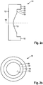
- FIGs. 2a and 2b depict the negative lens 11 in a similar way to that described with respect to Figs. 1a and 1b .
- the negative lens 11 is a plano-convex lens, having a planar surface 12 on a first face and a concave optical surface 13 on a second face.
- the negative lens 11 comprises a circumferential rim 14 having a ring-shaped planar surface 15 that is arranged symmetrically with respect to an optical axis 16 of the negative lens 11.
- a recess 17 is arranged on the inner side of the rim 14, being formed by a step 18 and a planar back-surface 19.
- the symmetrical structure of the negative lens 11 is seen clearly in Fig. 2b .
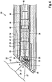
- a section of an oblique-view endoscope objective 20 is shown in a longitudinal cross section, illustrating in an exemplary manner how the negative lens 1 according to the embodiment of Figs. 1a and 1b may be integrated into an endoscope objective 20. It is to be understood that instead, the negative lens 11 shown in Figs. 2a and 2b could be employed in the endoscope objective 20. In Fig. 3 only a section of the oblique-view endoscope objective 20 is shown, the objective comprising further optical elements not shown.
- the optical system of the endoscope objective 20 comprises a glass plate 21 forming a cover plate of the endoscope objective 20, a plano-concave negative lens 1 and a wedge-shaped deflection prism 22.
- the deflection prism 22 has an entrance face formed by a planar surface 23 and an exit face 24.
- the deflection prism 22 consists of two cemented prismatic elements 22', 22" having a planar interface 25.
- a first reflective plane of the deflection prism 22 is formed by the interface 25 which may comprise a reflective layer.
- a second reflective plane of the deflection prism 22 is formed by the planar surface 23, i.e. by the entrance face.
- the exit face 24 of the deflection prism 22 is cemented to a further optical element which may be a glass block 26 or a positive lens, for example.
- the negative lens 1 is cemented with its planar surface 5 upon the entrance face of the deflection prism 22, i.e. on the planar surface 23.
- the cover glass 21 is cemented on the planar optical surface 2 of the negative lens 1, but may be as well arranged with an air gap between the cover glass 21 and the negative lens 1.
- the recess 7 is arranged on the planar surface 23 of the deflection prism 22 displaced from the concave optical surface 3 in a half-plane defined by the viewing direction and the longitudinal axis of the endoscope objective.
- the incident rays 27 coming from an object field are transmitted through the glass plate 21, the negative lens 1 and the planar surface 23 to enter into the deflection prism 22, are reflected on the interface 25 of the deflection prism 22 towards the planar surface 23, and are totally reflected on the planar surface 23 of the deflection prism 22 into the direction of a longitudinal axis of the endoscope objective 20. Due to the cavity 28 formed by the concave optical surface 3 and the recess 7 extending to one side of the concave optical surface 3, that fraction of the area of the planar surface 23 that can be employed for total internal reflection is extended into a direction needed for a larger fraction of rays to be reflected into the proximal longitudinal direction.
- the endoscope shaft 30 comprises a rigid outer shaft 31 having a distal end face 32 that is oblique to a longitudinal axis of the shaft 30, corresponding to an oblique viewing direction of, for example, 45°.
- the shaft 30 comprises an inner shaft forming a space 34 between the inner shaft and the outer shaft 31, the space 34 accommodating optical fibres 35 (not shown in detail) for transmitting illumination light to the distal end face 32 for illuminating an object field 36.
- the optical system of the endoscope objective 20 comprises the negative lens 1, the deflection prism 22, the glass block 26 (see Fig. 3 ) and further lenses 37, 38, 39 which may be single lenses or cemented doublets, for example.
- the lenses 39, 38, and a unit formed by the lens 37, glass block 26, deflection prism 22, and negative lens 1 are held in a distal end section of an optics tube 40; the last-mentioned unit may also comprise the glass plate 21.
- Appropriate air gaps between the lenses 37, 38, and 39 are maintained by ring-shaped spacers 41, 42. Further in a proximal direction the optics tube 40 may accommodate an arrangement of relay lenses (not shown).
- the deflection prism 22 that consists of two prismatic elements 22', 22" is cemented to the glass block 26. As depicted in Fig. 4 , the recess 7 of the negative lens 1 is arranged such that the rays 27 are totally reflected on that part of the planar surface 23 of the deflection prism 22 on the distal side of which an air-filled space or air layer is formed by the concave optical surface 3 and the recess 7.
- a section of an endoscope objective 50 according to a further embodiment is shown in a view corresponding to that of Fig. 3 .
- the negative lens 51 is a bi-concave lens, having a first concave optical surface 52 on its first face and a second concave optical surface 53 on its second face.
- the second concave optical surface 53 is encompassed by a closed rim 54 which may have a planar surface.
- the negative lens 51 is directly cemented upon the first planar surface 23 of the deflection prism 22, the rim 54 abutting the planar surface 23 of the deflection prism 22.
- the other optical elements of the endoscope objective including a glass plate 21 cemented upon an outer rim encompassing the first concave optical surface, are configured as described above (see Figs. 3 and 4 ).
- the rays 27 are totally reflected on that part of the planar surface 23 of the deflection prism 22 which is covered by an air-filled space, however, in this case the air-filled space is provided by the cavity 55 formed by the second concave surface 53 only.
Description
- The present invention relates to an endoscope objective comprising a deflection prism, the deflection prism having an entrance face, and a negative lens, the negative lens having a first face with a first optical surface and a second face with a second optical surface opposing the first optical surface, the second optical surface being a concave optical surface.
- Endoscopic examination techniques have prevailed in a multiplicity of medical and veterinary fields of application, as well as in many non-medical fields. In such examination techniques, an endoscope, which has an elongate shaft with an imaging optical system, is introduced into an internal cavity of a human or animal body or another object to be examined. The elongate shaft that is configured for being inserted into the cavity of the body or other object may be rigid, semi-rigid or flexible. In a distal (i.e. distant from a user) end section of the elongate shaft an endoscope objective is arranged for generating in an image plane an image of an object field in the cavity of the body or object, wherein the endoscope objective typically comprises one or more negative lenses. The generated image is transmitted to a proximal (i.e. close to a user) end of the endoscope for being viewed by the user or picked up by an electronic image sensor which is connected to a display and/or storage device. For transmitting the image from the distal to the proximal end section of the endoscope, the elongate shaft may comprise a fiber optic image guide or a sequence of relay lenses. Alternatively, the image generated by the endoscope objective may be picked up by an electronic image sensor arranged in the distal end section of the shaft and transmitted electronically towards the proximal end section of the endoscope.
- Depending on an intended application, endoscopes with various viewing angles are known. In particular, oblique-view endoscopes are known which have a viewing direction that deviates from a longitudinal axis of the shaft. Such oblique-view endoscopes typically have a rigid shaft the distal end of which comprises a cover glass mounted at an oblique angle in a distal opening of the shaft. The cover glass forms a distal window for light rays coming from the object field and entering into the endoscope objective. The objective of such an oblique-view endoscope usually comprises one or several lenses and at least one deflection prism for deflecting light entering at an oblique angle through the distal window into the objective in a direction parallel or almost parallel to the longitudinal axis of the shaft. According to a well-known optical design of objectives for oblique-view endoscopes, the incident light rays, after passing through the cover glass and a first group of objective lenses, enter into the deflection prism through an obliquely arranged entrance face of the deflection prism. On their path through the deflection prism, the rays are reflected twice. The first reflection occurs on a first reflective plane of the deflection prism which is oblique to the longitudinal axis, the rays being reflected back towards the entrance face. The second reflection, which may be a total internal reflection, occurs on the entrance face, which serves as a second reflective plane. After the second reflection, the incident light rays have a direction for entering into another group of objective lenses, being focused in an image plane of the endoscope objective for forming an image of the object field.
- According to this optical design, the entrance face of the deflection prism has a twofold function. First, it must permit transmission of the incident rays so that the rays can pass towards the first reflective plane, and second, it must permit reflection, preferably total reflection, of the rays being reflected back by the first reflective plane into a desired direction, which is generally parallel to the longitudinal axis. In order to permit total reflection and to guarantee low losses, the entrance face must provide a sufficient difference of refractive indices from the inside to the outside of the deflection prism.
- In
US 4,815,833 , an objective for endoscopes is disclosed comprising an elongated prism on a distal end thereof which is joined by cementing a diaphragm and a negative lens. A wedge-shaped angular diaphragm, made from metal or opaque glass, is cemented directly to an obliquely cut surface of the distal end portion of the prism. The negative lens is cemented to the distal side of the diaphragm. - The image beam from the lens passes through a central opening of the diaphragm and through a surface of the prism that does not have a reflective coating. The beam then strikes another surface of the prism and is reflected back to the first mentioned surface. This time, the angle of incidence is so large that total internal reflection takes place and the image beam is projected along the axis of the prism.
- In
US 4,850,342 , a hard endoscope of oblique-view type is described in which an objective front lens is arranged in parallel with a plane of a cover glass at a slight gap and is fixed to an objective prism with a frame. - Further, it is known to arrange a keyhole-shaped diaphragm between the deflection prism and a negative lens mounted on the deflection prism, in order to provide an air layer on the first surface of the deflection prism that is employed for total reflection.
- The positioning of a diaphragm or a frame between the deflection prism and the negative lens is problematic and may increase production cost. Further, dust grains may be caught, reducing the optical quality of the objective.
- According to
DE 197 36 617 A1 , in an endoscope objective having a direction of view including an angle different from zero with the longitudinal axis of the endoscope, on a surface of a prism unit a thin layer is deposited having a refractive index that is smaller than the refractive index of the material of the prism unit. The thin layer provides for total reflection on the corresponding surface of the prism unit. Thus, if an optical element of the objective is placed on the thin layer, no mechanical spacer is needed. However, the thin layer may lead to an increase of production cost, may have non-optimal anti-reflection properties, and the refractive index of the thin layer may undesirably limit the range of incidence angles at which total reflection occurs. - In
US 2011/242807 A1 a light cover and an illuminating apparatus applying the light cover are disclosed. The light cover comprises a substrate and a plurality of asymmetric lenses. Each of the asymmetric lenses has a light incident surface which is concave for accommodating a corresponding light source and receiving light emitted from the light source. - According to
US 2012/140336 A1 , a plastic lens has a first surface and a second surface, wherein the second surface includes an optically functional concave aspect, and a recess formed along an outer perimeter of the concave aspect. On a peripheral surface a gate portion is formed at a position where a resin injection outlet is arranged during formation of the plastic lens. - It is therefore an object of the present invention to provide an endoscope objective which alleviates the above mentioned problems. In particular, it is an object of the invention to provide an endoscope objective comprising a negative lens that can be mounted on a surface of a deflection prism of the endoscope objective in a cost-saving and efficient manner without deteriorating the image quality. It is another object of the present invention to provide an endoscope objective comprising a negative lens that can be assembled in a cost-saving and efficient manner without deterioration of the image quality.
- These objects are met by an endoscope objective according to claim 1. Advantageous embodiments of the present invention are indicated in the dependent claims.
- According to a first aspect of the present invention, a negative lens is provided, i.e. a lens having negative refractive power. Preferably, the negative lens is a single lens. However, the negative lens may be a cemented doublet or triplet having overall negative refractive power. The negative lens has a first face having a first optical surface, and a second face having a second optical surface, the first and second optical surfaces being arranged in an opposed relationship, such that light impinging on the first optical surface at a limited angle to an optical axis of the lens passes through the lens and exits the lens through the second optical surface. The optical axis is an axis of symmetry of the optical surfaces. The negative lens is made of a transparent material, in particular optical glass. The second optical surface is a concave optical surface, preferably having spherical shape. The first and/or second optical surfaces of the negative lens may have an anti-reflective coating.
- In accordance with the present invention, a recess is formed in the second face, the recess being adjacent to the concave optical surface. In particular, a surface of the recess is joined to the concave optical surface or forms a continuation of the concave optical surface. The concave optical surface and the surface of the recess may merge to form a continuous surface.
- When the negative lens is mounted on a planar surface with its second face being directed towards the planar surface, the concave optical surface forms a cavity, and the recess forms a continuation of the cavity or, in other words, the cavities formed by the concave optical surface and by the recess merge to form an enlarged combined cavity. The combined cavity may be filled with air, thus forming an air layer on the planar surface. When the planar surface upon which the negative lens is mounted is a surface of an optical element employed for internal total reflection, the air layer serves to provide a small refractive index outside the optical element and thus a large difference of refractive indices between the inside and the outside of the optical element. This permits a large range of incidence angles of rays being totally internally reflected on the planar surface of the optical element. Further, as the recess serves to enlarge the cavity defined by the concave optical surface and thus serves to enlarge the area of the planar surface covered by the air layer, the total area of the planar surface of the optical element available for total internal reflection is enlarged. This permits an enlarged fraction of rays transmitted inside the optical element to the planar surface to be totally internally reflected. The negative lens may be configured for being directly mounted on the planar surface of the optical element, a partial area of the second face touching the planar surface.
- Preferably, the negative lens is configured for being employed in an objective of an endoscope, in particular in the objective of an oblique-view endoscope. The negative lens may be configured for being arranged on an entrance face of a deflection prism of the endoscope objective, in particular for being cemented directly onto the entrance face, such that the entrance face is crossed by the incident rays and, after a first reflection, the rays are totally internally reflected on the same surface of the deflection prism. When the negative lens is mounted on the entrance of the deflection prism, the ability of the objective to collect incident light and to form an image of an object field is improved. Due to the increased fraction of the surface of the prism that can be employed for total reflection, the negative lens according to the invention permits a more convenient design of the optical system. Further, the negative lens can be mounted in a simple and efficient manner on the deflection prism forming a stable unit.
- Preferably, the negative lens is a plano-concave lens. A plano-concave lens is particularly suitable for being used in an oblique-view endoscope objective and, in particular, for being cemented on the entrance face of the deflection prism of an oblique-view endoscope objective.
- In a plano-concave lens, the optical axis is perpendicular to the first optical surface, which is a planar surface, and crosses the concave optical surface at its apex. Alternatively, the negative lens may be a bi-concave lens or a negative meniscus lens.
- Advantageously, the negative lens on its second face exhibits a rim encompassing the concave optical surface and the recess, the rim having a planar surface. The second face of the negative lens thus is formed by the concave optical surface, the surface of the recess being interconnected to the concave optical surface, and the planar surface of the rim. If the recess is formed by removing lens material out of the second face of the negative lens, the rim may be considered a remaining part of the second face that protrudes over the concave optical surface and the surface of the recess. Preferably, the rim forms a closed ring, and the planar surface is a closed surface encompassing the concave optical surface and the recess. In particular, the planar surface of the rim is perpendicular to the optical axis of the lens. The planar surface of the rim is particularly suitable for cementing the negative lens upon a planar surface, for example on the entrance face of a deflection prism of an oblique-view endoscope objective, being flush with the surface of the deflection prism. In this way, most secure fixation of the negative lens on the planar surface is facilitated.
- According to a preferred embodiment of the invention, the recess is configured asymmetrically with respect to the concave optical surface, and, in particular, asymmetrically with respect to the optical axis of the negative lens. Advantageously, the recess extends from the concave optical surface in one lateral direction only or predominantly, thereby enlarging in the lateral direction the cavity formed by the concave optical surface when the negative lens is mounted on a planar surface. The recess thus serves to enlarge the area of a planar surface of an optical element usable for total internal reflection, if the negative lens is arranged on the surface with the recess extending in such a lateral direction in which rays to be totally internally reflected are displaced with respect to the optical axis of the negative lens.
- According to an alternative embodiment of the invention, the recess is configured symmetrically with respect to the concave optical surface, i.e. symmetrically with respect to the optical axis of the negative lens. In this case, the rim can be considered forming a ring-shaped base of the negative lens on its second face. When a negative lens having a symmetric recess is mounted on a planar surface of an optical element, the fraction of the surface that can be used for total reflection is enlarged.
- Preferably, the recess is a step-shaped depression. If the recess is asymmetric, the step may merge into the concave optical surface. If the recess is symmetric, the step may be circular, encompassing the concave optical surface in a symmetric manner. A step-shaped depression in the second face of the negative lens can be manufactured easily and provides a well-defined extension of the cavity formed by the concave surface.
- Advantageously, a back-surface of the recess is a planar surface. In this way a well-defined air layer is provided if the negative lens is mounted on a planar surface. The back-surface preferably is polished for avoiding dust and to facilitate clean assembly, but need not necessarily be of optical quality.
- Preferably, the negative lens is formed in one piece. In particular, the negative lens may be manufactured by grinding out of one block of transparent material. In this way, manufacturing is facilitated and stability is enhanced.
- In accordance with the present invention an endoscope objective is provided that comprises a deflection prism and a negative lens, in particular an oblique-view endoscope objective is provided. The negative lens preferably is a single lens, but may be a cemented doublet or triplet having overall negative refractive power. The negative lens has a first face with a first optical surface and a second face with a second optical surface opposing the first optical surface. The second optical surface is a concave optical surface, preferably a spherical surface. The deflection prism has an entrance face and an exit face. The entrance face and/or the exit face may exhibit an anti-reflective coating. The negative lens is arranged to a distal side of the entrance face of the deflection prism. The deflection prism has at least two reflective planes, one of which is formed by the entrance face. A first reflective plane may be arranged for at least partially reflecting light rays having entered through the entrance face into the deflection prism, in a partially backwards direction towards the entrance face. The entrance face, which forms the second reflective plane, preferably is arranged for reflecting by total internal reflection light rays coming from the first reflective plane towards the exit face. The exit face of the deflection prism may be a planar surface perpendicular to a longitudinal axis of the endoscope objective. The endoscope objective further comprises a proximal lens group arranged on a proximal side of the deflection prism, the proximal lens group having overall positive refractive power for generating an image of the object field in an image plane. The endoscope objective may comprise a cover glass arranged on a distal side of the negative lens. The endoscope objective may comprise further elements, such as spacers and diaphragms.
- In accordance with the invention, the negative lens is mounted on the entrance face of the deflection prism such that a rim encompassing the concave optical surface of the second face of the lens abuts the entrance face of the deflection prism. In particular, the negative lens is directly mounted on that planar surface that forms the entrance face of the deflection prism. Preferably the negative lens is directly cemented onto the planar surface, i.e. the rim directly touches the planar surface of the deflection prism or is separated only by a layer of optical cement from the planar surface, wherein the latter may have an anti-reflective coating. Therefore the concave optical surface of the second face of the negative lens and the entrance face of the deflection prism form a cavity that typically is filled with air, thus forming an air layer on the planar surface.
- The negative lens serves to collect rays coming from an object field to be observed, allowing for a large field of view. After having passed the negative lens, the rays enter into the deflection prism through the entrance face of the deflection prism. Thereafter rays are reflected internally in a partially backward direction towards the entrance face. In particular the rays are reflected by the first reflective plane towards the entrance face. On the entrance face, i.e. on the second reflective plane, total internal reflection occurs. By total internal reflection the rays preferably are directed towards the exit face of the deflection prism. Having exited the deflection prism through the exit face, the rays may enter into the proximal lens group, being focused in the image plane. The endoscope objective is designed such that the rays coming from the object field and having been internally reflected in the deflection prism towards the entrance face impinge on the entrance face in an area of the entrance face covered by the air layer formed by the concave optical surface of the second face of the negative lens.
- Due to the rays being internally reflected on the entrance face of the deflection prism in that part of its surface on the distal side of which the air-filled cavity is situated, a high difference between refractive indices inside and outside the deflection prism is provided, thus enhancing total reflection. Further, appropriate positioning of the air-filled cavity is facilitated by mounting the negative lens on the entrance face of the deflection prism, for example by directly cementing the negative lens upon the entrance face. In this way, an endoscope objective is provided that has improved characteristics regarding the ability to collect incident rays from the object field and to form an image of the object field, and that can be assembled in a simple, stable and cost-efficient manner.
- The negative lens is a negative lens as described above. In this case the combined cavity and the entrance face of the deflection prism form a cavity resulting in an air layer on the entrance face of the deflection prism, the combined cavity being formed by the concave optical surface of the second face of the negative lens and by the recess. In this way, the area of the entrance face usable for total internal reflection is increased.
- In particular, the endoscope objective is an oblique-view endoscope objective, i.e. is configured as an objective for an oblique-view endoscope, which may be a medical or a non-medical endoscope. The entrance face of the deflection prism may be arranged at an angle to a longitudinal axis of the endoscope objective. The oblique-view endoscope may be a rigid endoscope, the longitudinal axis of the distal end section of the shaft being a longitudinal axis of the shaft. For example, the oblique-view endoscope objective may have a viewing direction of about 45°. If the negative lens has a recess that is asymmetric with respect to the optical axis of the negative lens, the negative lens may be mounted on the entrance face of the deflection prism such that a lateral direction of displacement of the recess with respect to the optical axis is in a half-plane formed by a longitudinal axis of the endoscope objective and the viewing direction.
- According to a preferred embodiment of the endoscope objective, a viewing direction being defined by the optical axis of the negative lens forms an angle to the longitudinal axis of the endoscope objective. The entrance face of the deflection prism is substantially perpendicular to the optical axis of the negative lens, and the first reflective plane is inclined at about half the angle to the longitudinal axis of the endoscope objective. In particular, the deflection prism has only two reflective planes, which are the first reflective plane and the entrance face. Thus, the rays entering into the deflection prism through the entrance face are internally reflected twice and exit the deflection prism through the exit face. In this way an oblique-view endoscope objective having a simple and efficient optical design can be provided.
- Most preferably, the endoscope objective is configured such that substantially all rays that enter into the deflection prism through the entrance face are directed by the reflection on the first reflective plane towards that part of the entrance face that is covered by a cavity formed between the negative lens and the entrance face, i.e. by the concave optical surface of the second face of the negative lens and, if present, by the recess. In that part of the entrance face the air layer enhances total reflection, thus improving the light collecting and imaging properties of the endoscope objective.
- The features of the invention as mentioned above and as described below apply not only in the combinations mentioned but also in other combinations or alone, without leaving the scope of the present invention.
- Further aspects of the present invention will be apparent from the figures and from the description of a particular embodiment that follows.
-
Figs. 1a and 1b show a negative lens according to a first embodiment of the invention in an axial cross-section and in an axial view, respectively; -
Figs. 2a and 2b show a negative lens according to a second embodiment of the invention in an axial cross-section and in an axial view, respectively;Fig. 3 shows a section of an endoscope objective comprising a negative lens according to the embodiment ofFigs. 1a and 1b in a longitudinal cross section;Fig. 4 shows a distal end section of an oblique-view endoscope comprising the objective ofFig. 3 in a longitudinal cross section;Fig. 5 shows a section of an endoscope objective according to a further embodiment, which is not claimed, in a longitudinal cross section. - In
Fig. 1a , a negative lens according to a first embodiment of the invention is depicted in an axial cross-section. The negative lens 1 has a first face with a planaroptical surface 2 and a second face with a concaveoptical surface 3. The second face comprises an outer rim 4 having a ring-shapedplanar surface 5 that is perpendicular to theoptical axis 6 of the negative lens 1. Adjacent to the concaveoptical surface 3 and joining it, arecess 7 is formed having astep 8 and a planar back-surface 9. As can be seen in the axial view shown inFig. 1b , therecess 7 extends to one side of the concaveoptical surface 3 only. The concaveoptical surface 3 and therecess 7 are encompassed by theplanar surface 5. - An alternative embodiment of the negative lens is shown in
Figs. 2a and 2b which depict thenegative lens 11 in a similar way to that described with respect toFigs. 1a and 1b . Thenegative lens 11 is a plano-convex lens, having aplanar surface 12 on a first face and a concaveoptical surface 13 on a second face. Thenegative lens 11 comprises acircumferential rim 14 having a ring-shapedplanar surface 15 that is arranged symmetrically with respect to anoptical axis 16 of thenegative lens 11. In a symmetrical manner, arecess 17 is arranged on the inner side of therim 14, being formed by a step 18 and a planar back-surface 19. The symmetrical structure of thenegative lens 11 is seen clearly inFig. 2b . - In
Fig. 3 , a section of an oblique-view endoscope objective 20 is shown in a longitudinal cross section, illustrating in an exemplary manner how the negative lens 1 according to the embodiment ofFigs. 1a and 1b may be integrated into anendoscope objective 20. It is to be understood that instead, thenegative lens 11 shown inFigs. 2a and 2b could be employed in theendoscope objective 20. InFig. 3 only a section of the oblique-view endoscope objective 20 is shown, the objective comprising further optical elements not shown. - The optical system of the
endoscope objective 20 comprises aglass plate 21 forming a cover plate of theendoscope objective 20, a plano-concave negative lens 1 and a wedge-shapeddeflection prism 22. Thedeflection prism 22 has an entrance face formed by aplanar surface 23 and anexit face 24. Thedeflection prism 22 consists of two cementedprismatic elements 22', 22" having aplanar interface 25. A first reflective plane of thedeflection prism 22 is formed by theinterface 25 which may comprise a reflective layer. A second reflective plane of thedeflection prism 22 is formed by theplanar surface 23, i.e. by the entrance face. Theinterface 25 is inclined with respect to a longitudinal direction of the endoscope objective by about half the angle at which theplanar surface 23 is inclined. If the viewing direction is 45°, the planar surface is inclined at about α = 45° to the longitudinal axis, and the interface at about α/2 = 22.5°. On its proximal side, theexit face 24 of thedeflection prism 22 is cemented to a further optical element which may be aglass block 26 or a positive lens, for example. The negative lens 1 is cemented with itsplanar surface 5 upon the entrance face of thedeflection prism 22, i.e. on theplanar surface 23. Thecover glass 21 is cemented on the planaroptical surface 2 of the negative lens 1, but may be as well arranged with an air gap between thecover glass 21 and the negative lens 1. As shown inFig. 3 , therecess 7 is arranged on theplanar surface 23 of thedeflection prism 22 displaced from the concaveoptical surface 3 in a half-plane defined by the viewing direction and the longitudinal axis of the endoscope objective. - The incident rays 27 coming from an object field are transmitted through the
glass plate 21, the negative lens 1 and theplanar surface 23 to enter into thedeflection prism 22, are reflected on theinterface 25 of thedeflection prism 22 towards theplanar surface 23, and are totally reflected on theplanar surface 23 of thedeflection prism 22 into the direction of a longitudinal axis of theendoscope objective 20. Due to thecavity 28 formed by the concaveoptical surface 3 and therecess 7 extending to one side of the concaveoptical surface 3, that fraction of the area of theplanar surface 23 that can be employed for total internal
reflection is extended into a direction needed for a larger fraction of rays to be reflected into the proximal longitudinal direction. - In
Fig. 4 , the above described endoscope objective 20 as mounted in a distal end section of ashaft 30 of an oblique-view endoscope is shown in a longitudinal cross-section. Theendoscope shaft 30 comprises a rigidouter shaft 31 having adistal end face 32 that is oblique to a longitudinal axis of theshaft 30, corresponding to an oblique viewing direction of, for example, 45°. Theshaft 30 comprises an inner shaft forming aspace 34 between the inner shaft and theouter shaft 31, thespace 34 accommodating optical fibres 35 (not shown in detail) for transmitting illumination light to thedistal end face 32 for illuminating anobject field 36. The optical system of theendoscope objective 20 comprises the negative lens 1, thedeflection prism 22, the glass block 26 (seeFig. 3 ) andfurther lenses lenses lens 37,glass block 26,deflection prism 22, and negative lens 1 are held in a distal end section of anoptics tube 40; the last-mentioned unit may also comprise theglass plate 21. Appropriate air gaps between thelenses spacers optics tube 40 may accommodate an arrangement of relay lenses (not shown). - Light rays 27 coming from the
object field 36 enter into theendoscope objective 20 throughglass plate 21 and are collected by negative lens 1. As described above (seeFig. 3 ), the light rays 27 enter through theplanar surface 23 into thedeflection prism 22, are back-reflected on theinterface 25 and are reflected by total internal reflection on theplanar surface 23 into a substantially axial direction. The rays are then transmitted throughglass block 26 and are focused bypositive lenses image plane 43. The image formed in theimage plane 43 is transmitted by relay lenses (not shown) to the proximal end of the endoscope. The negative lens 1 is cemented directly upon theplanar surface 23 of thedeflection prism 22. Thedeflection prism 22 that consists of twoprismatic elements 22', 22" is cemented to theglass block 26. As depicted inFig. 4 , therecess 7 of the negative lens 1 is arranged such that therays 27 are totally reflected on that part of the planar
surface 23 of thedeflection prism 22 on the distal side of which an air-filled space or air layer is formed by the concaveoptical surface 3 and therecess 7. - In
Fig. 5 a section of anendoscope objective 50 according to a further embodiment is shown in a view corresponding to that ofFig. 3 . As opposed to the embodiment depicted inFig. 3 , in this case thenegative lens 51 is a bi-concave lens, having a first concaveoptical surface 52 on its first face and a second concaveoptical surface 53 on its second face. The second concaveoptical surface 53 is encompassed by aclosed rim 54 which may have a planar surface. As shown inFig. 5 , thenegative lens 51 is directly cemented upon the firstplanar surface 23 of thedeflection prism 22, therim 54 abutting theplanar surface 23 of thedeflection prism 22. The other optical elements of the endoscope objective, including aglass plate 21 cemented upon an outer rim encompassing the first concave optical surface, are configured as described above (seeFigs. 3 and4 ). As in that embodiment, therays 27 are totally reflected on that part of theplanar surface 23 of thedeflection prism 22 which is covered by an air-filled space, however, in this case the air-filled space is provided by thecavity 55 formed by the secondconcave surface 53 only. - For clarity not all reference numerals are displayed in all figures. If a reference numeral is not explicitly mentioned in the description of a figure, it has the same meaning as in the other figures.
-
- 1
- Negative lens
- 2
- Planar optical surface
- 3
- Concave optical surface
- 4
- Rim
- 5
- Planar surface
- 6
- Optical axis
- 7
- Recess
- 8
- Step
- 9
- Back-surface
- 11
- Negative lens
- 12
- Planar surface
- 13
- Concave optical surface
- 14
- Rim
- 15
- Planar surface
- 16
- Optical axis
- 17
- Recess
- 18
- Step
- 19
- Back-surface
- 20
- Endoscope objective
- 21
- Glass plate
- 22
- Deflection prism
- 22', 22"
- Prismatic element
- 23
- First surface
- 24
- Exit face
- 25
- Interface
- 26
- Glass block
- 27
- Ray
- 28
- Cavity
- 30
- Shaft
- 31
- Outer shaft
- 32
- End face
- 34
- Space
- 35
- Optical fibres
- 36
- Object field
- 37
- Lens
- 38
- Lens
- 39
- Lens
- 40
- Optics tube
- 41
- Spacer
- 42
- Spacer
- 43
- Image plane
- 50
- Objective
- 51
- Negative lens
- 52
- Concave optical surface
- 53
- Concave optical surface
- 54
- Rim
- 55
- Cavity
Claims (11)
- Endoscope objective, comprising a deflection prism (22) having an entrance face, and comprising a negative lens (1, 11) having a first face with a first optical surface and a second face with a second optical surface opposing the first optical surface, the second optical surface being a concave optical surface (3, 13), wherein the negative lens (1, 11) is mounted on the entrance face of the deflection prism (22) such that a rim (4, 14) encompassing the concave optical surface (3, 13) abuts the entrance face of the deflection prism (22), characterized in that a recess (7, 17) is formed in the second face, the recess (7, 17) being adjacent to the concave optical surface (3, 13).
- Endoscope objective according to claim 1, characterized in that the negative lens (1, 11) is a plano-concave lens.
- Endoscope objective according to claim 1 or 2, characterized in that the rim (4, 14) encompasses the concave optical surface (3, 13) and the recess (7, 17), the rim (4, 14) having a planar surface (5, 15).
- Endoscope objective according to any one of the preceding claims, characterized in that the recess (7) is asymmetric with respect to an optical axis (6) of the negative lens (1).
- Endoscope objective according to claim 4, characterized in that the recess (7) extends from the concave optical surface (3) in one lateral direction.
- Endoscope objective according to any one of claims 1-3, characterized in that the recess (17) is symmetric with respect to an optical axis (16) of the negative lens (11).
- Endoscope objective according to any one of the preceding claims, characterized in that the recess (7, 17) is a step-shaped depression.
- Endoscope objective according to any one of the preceding claims, characterized in that a back-surface (9, 19) of the recess (7, 17) is planar.
- Endoscope objective according to any one of the preceding claims, characterized in that the negative lens (1, 11) is formed in one piece.
- Endoscope objective according to any one of the preceding claims, characterized in that the optical axis (6, 16) of the negative lens (1, 11) forms an angle α to a longitudinal axis of the endoscope objective (20), that the entrance face of the deflection prism is substantially perpendicular to the optical axis (6, 16) of the negative lens (1, 11), and that a first reflective plane of the deflection prism is inclined at about α/2 to the longitudinal axis of the endoscope objective (20).
- Endoscope objective according to any one of the preceding claims, characterized in that the endoscope objective (20) is configured such that substantially all rays entering into the deflection prism (22) through the entrance face of the deflection prism (22) are directed by reflection on a first reflective plane of the deflection prism (22) towards that part of the entrance face that is covered by a cavity (28) formed between the negative lens (1, 11) and the entrance face such that the rays are totally internally reflected on this part of the entrance face.
Priority Applications (2)
| Application Number | Priority Date | Filing Date | Title |
|---|---|---|---|
| US15/818,942 US10725282B2 (en) | 2016-11-22 | 2017-11-21 | Negative lens and endoscope objective |
| US16/863,213 US11428923B2 (en) | 2016-11-22 | 2020-04-30 | Negative lens and endoscope objective |
Applications Claiming Priority (1)
| Application Number | Priority Date | Filing Date | Title |
|---|---|---|---|
| DE102016122429.4A DE102016122429A1 (en) | 2016-11-22 | 2016-11-22 | Negative lens and endoscope lens |
Publications (3)
| Publication Number | Publication Date |
|---|---|
| EP3333599A2 EP3333599A2 (en) | 2018-06-13 |
| EP3333599A3 EP3333599A3 (en) | 2018-08-08 |
| EP3333599B1 true EP3333599B1 (en) | 2019-05-01 |
Family
ID=60387797
Family Applications (1)
| Application Number | Title | Priority Date | Filing Date |
|---|---|---|---|
| EP17001867.5A Active EP3333599B1 (en) | 2016-11-22 | 2017-11-15 | Endoscope objective |
Country Status (3)
| Country | Link |
|---|---|
| US (2) | US10725282B2 (en) |
| EP (1) | EP3333599B1 (en) |
| DE (1) | DE102016122429A1 (en) |
Families Citing this family (11)
| Publication number | Priority date | Publication date | Assignee | Title |
|---|---|---|---|---|
| EP3544482A4 (en) | 2016-11-28 | 2020-07-22 | Adaptivendo LLC | Endoscope with separable, disposable shaft |
| DE102017113273A1 (en) * | 2017-06-16 | 2018-12-20 | avateramedical GmBH | Lens for an endoscope and endoscope |
| DE102018102268A1 (en) * | 2018-02-01 | 2019-08-01 | Olympus Winter & Ibe Gmbh | Optical system of a stereo video endoscope |
| WO2019193933A1 (en) * | 2018-04-02 | 2019-10-10 | オリンパス株式会社 | Light path deflection prism for endoscope, and oblique-viewing endoscope optical system |
| US10497820B1 (en) * | 2018-06-01 | 2019-12-03 | Globalfoundries Singapore Pte. Ltd. | Wedge-shaped fiber array on a silicon-photonic device and method for producing the same |
| CN109061872B (en) * | 2018-08-06 | 2021-05-11 | 宁波永新光学股份有限公司 | Endoscope objective optical system |
| US11311184B2 (en) | 2018-08-24 | 2022-04-26 | Ambu A/S | Tip part for a vision device |
| EP3613326B1 (en) | 2018-08-24 | 2023-09-20 | Ambu A/S | A tip part for a vision device |
| EP3613327A1 (en) | 2018-08-24 | 2020-02-26 | Ambu A/S | A tip part for a vision device |
| USD1018844S1 (en) | 2020-01-09 | 2024-03-19 | Adaptivendo Llc | Endoscope handle |
| CN116499975B (en) * | 2023-06-29 | 2023-09-22 | 之江实验室 | Prism device for optical surface wave sensor and design and installation method thereof |
Citations (5)
| Publication number | Priority date | Publication date | Assignee | Title |
|---|---|---|---|---|
| US4850342A (en) | 1982-05-01 | 1989-07-25 | Olympus Optical Co., Ltd. | Hard endoscope of oblique view type |
| US5051824A (en) | 1989-10-30 | 1991-09-24 | Olympus Optical Co., Ltd. | Electronic scope having detachable frame to which solid state imaging device is fastened |
| DE19736617A1 (en) | 1997-08-22 | 1999-03-11 | Storz Karl Gmbh & Co | Endoscope lens |
| EP2165640A1 (en) | 2008-09-19 | 2010-03-24 | Olympus Medical Systems Corp. | Endoscope for oblique viewing |
| US20120140336A1 (en) | 2010-12-02 | 2012-06-07 | Tamron Co., Ltd. | Plastic lens |
Family Cites Families (5)
| Publication number | Priority date | Publication date | Assignee | Title |
|---|---|---|---|---|
| JPS56128914A (en) * | 1980-03-06 | 1981-10-08 | Minolta Camera Co Ltd | Projector lens for video projector |
| DE3640186C3 (en) | 1986-11-25 | 1994-08-11 | Wolf Gmbh Richard | Process for the production of an objective for endoscopes |
| US5980453A (en) * | 1996-02-22 | 1999-11-09 | Precision Optics Corporation | Endoscope with low distortion |
| DE102004042023B4 (en) * | 2004-08-27 | 2013-10-31 | Jenoptik Polymer Systems Gmbh | Optical assembly and method for its assembly |
| US20110242807A1 (en) * | 2010-03-31 | 2011-10-06 | Aphos Lighting Llc | Light cover and illuminating apparatus applying the same |
-
2016
- 2016-11-22 DE DE102016122429.4A patent/DE102016122429A1/en not_active Withdrawn
-
2017
- 2017-11-15 EP EP17001867.5A patent/EP3333599B1/en active Active
- 2017-11-21 US US15/818,942 patent/US10725282B2/en active Active
-
2020
- 2020-04-30 US US16/863,213 patent/US11428923B2/en active Active
Patent Citations (5)
| Publication number | Priority date | Publication date | Assignee | Title |
|---|---|---|---|---|
| US4850342A (en) | 1982-05-01 | 1989-07-25 | Olympus Optical Co., Ltd. | Hard endoscope of oblique view type |
| US5051824A (en) | 1989-10-30 | 1991-09-24 | Olympus Optical Co., Ltd. | Electronic scope having detachable frame to which solid state imaging device is fastened |
| DE19736617A1 (en) | 1997-08-22 | 1999-03-11 | Storz Karl Gmbh & Co | Endoscope lens |
| EP2165640A1 (en) | 2008-09-19 | 2010-03-24 | Olympus Medical Systems Corp. | Endoscope for oblique viewing |
| US20120140336A1 (en) | 2010-12-02 | 2012-06-07 | Tamron Co., Ltd. | Plastic lens |
Also Published As
| Publication number | Publication date |
|---|---|
| DE102016122429A1 (en) | 2018-05-24 |
| US20200264424A1 (en) | 2020-08-20 |
| US11428923B2 (en) | 2022-08-30 |
| US10725282B2 (en) | 2020-07-28 |
| EP3333599A2 (en) | 2018-06-13 |
| US20180143421A1 (en) | 2018-05-24 |
| EP3333599A3 (en) | 2018-08-08 |
Similar Documents
| Publication | Publication Date | Title |
|---|---|---|
| EP3333599B1 (en) | Endoscope objective | |
| JP6898460B2 (en) | Flexible camera lens design | |
| US5980454A (en) | Endoscopic imaging system employing diffractive optical elements | |
| US5416638A (en) | Disposable endoscope | |
| JP4843121B2 (en) | Objective optical system | |
| US8842208B2 (en) | Optical fiber scanning probe | |
| WO2012081349A1 (en) | Endoscope optical system | |
| JPH10239594A (en) | Electronic endoscope | |
| JP2016538064A (en) | Optical coherence tomography probe | |
| EP1019756A1 (en) | Sapphire objective system | |
| JP2001311880A (en) | Compact confocal optical system | |
| JPH06317744A (en) | Optical system for endoscopic objective lens | |
| JPH0511196A (en) | Visual field direction conversion optical system for endoscope | |
| JPH0814661B2 (en) | View conversion optical system | |
| JP6873741B2 (en) | Imaging device | |
| US20120265018A1 (en) | Endoscope | |
| JP2014149481A (en) | Object lens for endoscope, and endoscope | |
| JP2009276502A (en) | Illumination optical system for endoscope | |
| US20200297203A1 (en) | Endoscope | |
| US20070091446A1 (en) | Optical apparatus with off-axis direction-of-view | |
| EP4152071A1 (en) | Optical imaging lens assembly and endoscopic optical device | |
| JP2002040359A (en) | Optical scanning optical system | |
| JP3559361B2 (en) | Endoscope eyepiece optical system | |
| JP2004229963A (en) | Scanning optical system | |
| JP4131008B2 (en) | End of the endoscope |
Legal Events
| Date | Code | Title | Description |
|---|---|---|---|
| PUAI | Public reference made under article 153(3) epc to a published international application that has entered the european phase |
Free format text: ORIGINAL CODE: 0009012 |
|
| STAA | Information on the status of an ep patent application or granted ep patent |
Free format text: STATUS: THE APPLICATION HAS BEEN PUBLISHED |
|
| AK | Designated contracting states |
Kind code of ref document: A2 Designated state(s): AL AT BE BG CH CY CZ DE DK EE ES FI FR GB GR HR HU IE IS IT LI LT LU LV MC MK MT NL NO PL PT RO RS SE SI SK SM TR |
|
| AX | Request for extension of the european patent |
Extension state: BA ME |
|
| PUAL | Search report despatched |
Free format text: ORIGINAL CODE: 0009013 |
|
| AK | Designated contracting states |
Kind code of ref document: A3 Designated state(s): AL AT BE BG CH CY CZ DE DK EE ES FI FR GB GR HR HU IE IS IT LI LT LU LV MC MK MT NL NO PL PT RO RS SE SI SK SM TR |
|
| AX | Request for extension of the european patent |
Extension state: BA ME |
|
| RIC1 | Information provided on ipc code assigned before grant |
Ipc: G02B 23/24 20060101ALI20180703BHEP Ipc: A61B 1/00 20060101ALI20180703BHEP Ipc: G02B 23/02 20060101ALN20180703BHEP Ipc: G02B 3/00 20060101AFI20180703BHEP |
|
| STAA | Information on the status of an ep patent application or granted ep patent |
Free format text: STATUS: REQUEST FOR EXAMINATION WAS MADE |
|
| 17P | Request for examination filed |
Effective date: 20180920 |
|
| RBV | Designated contracting states (corrected) |
Designated state(s): AL AT BE BG CH CY CZ DE DK EE ES FI FR GB GR HR HU IE IS IT LI LT LU LV MC MK MT NL NO PL PT RO RS SE SI SK SM TR |
|
| RIC1 | Information provided on ipc code assigned before grant |
Ipc: G02B 23/02 20060101ALN20181129BHEP Ipc: G02B 23/24 20060101ALI20181129BHEP Ipc: G02B 3/00 20060101AFI20181129BHEP Ipc: A61B 1/00 20060101ALI20181129BHEP |
|
| GRAP | Despatch of communication of intention to grant a patent |
Free format text: ORIGINAL CODE: EPIDOSNIGR1 |
|
| STAA | Information on the status of an ep patent application or granted ep patent |
Free format text: STATUS: GRANT OF PATENT IS INTENDED |
|
| INTG | Intention to grant announced |
Effective date: 20190104 |
|
| GRAS | Grant fee paid |
Free format text: ORIGINAL CODE: EPIDOSNIGR3 |
|
| GRAA | (expected) grant |
Free format text: ORIGINAL CODE: 0009210 |
|
| STAA | Information on the status of an ep patent application or granted ep patent |
Free format text: STATUS: THE PATENT HAS BEEN GRANTED |
|
| AK | Designated contracting states |
Kind code of ref document: B1 Designated state(s): AL AT BE BG CH CY CZ DE DK EE ES FI FR GB GR HR HU IE IS IT LI LT LU LV MC MK MT NL NO PL PT RO RS SE SI SK SM TR |
|
| REG | Reference to a national code |
Ref country code: GB Ref legal event code: FG4D |
|
| REG | Reference to a national code |
Ref country code: CH Ref legal event code: EP Ref country code: AT Ref legal event code: REF Ref document number: 1127688 Country of ref document: AT Kind code of ref document: T Effective date: 20190515 |
|
| REG | Reference to a national code |
Ref country code: DE Ref legal event code: R096 Ref document number: 602017003542 Country of ref document: DE |
|
| REG | Reference to a national code |
Ref country code: IE Ref legal event code: FG4D |
|
| REG | Reference to a national code |
Ref country code: NL Ref legal event code: MP Effective date: 20190501 |
|
| REG | Reference to a national code |
Ref country code: LT Ref legal event code: MG4D |
|
| PG25 | Lapsed in a contracting state [announced via postgrant information from national office to epo] |
Ref country code: ES Free format text: LAPSE BECAUSE OF FAILURE TO SUBMIT A TRANSLATION OF THE DESCRIPTION OR TO PAY THE FEE WITHIN THE PRESCRIBED TIME-LIMIT Effective date: 20190501 Ref country code: LT Free format text: LAPSE BECAUSE OF FAILURE TO SUBMIT A TRANSLATION OF THE DESCRIPTION OR TO PAY THE FEE WITHIN THE PRESCRIBED TIME-LIMIT Effective date: 20190501 Ref country code: NL Free format text: LAPSE BECAUSE OF FAILURE TO SUBMIT A TRANSLATION OF THE DESCRIPTION OR TO PAY THE FEE WITHIN THE PRESCRIBED TIME-LIMIT Effective date: 20190501 Ref country code: SE Free format text: LAPSE BECAUSE OF FAILURE TO SUBMIT A TRANSLATION OF THE DESCRIPTION OR TO PAY THE FEE WITHIN THE PRESCRIBED TIME-LIMIT Effective date: 20190501 Ref country code: HR Free format text: LAPSE BECAUSE OF FAILURE TO SUBMIT A TRANSLATION OF THE DESCRIPTION OR TO PAY THE FEE WITHIN THE PRESCRIBED TIME-LIMIT Effective date: 20190501 Ref country code: NO Free format text: LAPSE BECAUSE OF FAILURE TO SUBMIT A TRANSLATION OF THE DESCRIPTION OR TO PAY THE FEE WITHIN THE PRESCRIBED TIME-LIMIT Effective date: 20190801 Ref country code: AL Free format text: LAPSE BECAUSE OF FAILURE TO SUBMIT A TRANSLATION OF THE DESCRIPTION OR TO PAY THE FEE WITHIN THE PRESCRIBED TIME-LIMIT Effective date: 20190501 Ref country code: PT Free format text: LAPSE BECAUSE OF FAILURE TO SUBMIT A TRANSLATION OF THE DESCRIPTION OR TO PAY THE FEE WITHIN THE PRESCRIBED TIME-LIMIT Effective date: 20190901 Ref country code: FI Free format text: LAPSE BECAUSE OF FAILURE TO SUBMIT A TRANSLATION OF THE DESCRIPTION OR TO PAY THE FEE WITHIN THE PRESCRIBED TIME-LIMIT Effective date: 20190501 |
|
| PG25 | Lapsed in a contracting state [announced via postgrant information from national office to epo] |
Ref country code: LV Free format text: LAPSE BECAUSE OF FAILURE TO SUBMIT A TRANSLATION OF THE DESCRIPTION OR TO PAY THE FEE WITHIN THE PRESCRIBED TIME-LIMIT Effective date: 20190501 Ref country code: GR Free format text: LAPSE BECAUSE OF FAILURE TO SUBMIT A TRANSLATION OF THE DESCRIPTION OR TO PAY THE FEE WITHIN THE PRESCRIBED TIME-LIMIT Effective date: 20190802 Ref country code: BG Free format text: LAPSE BECAUSE OF FAILURE TO SUBMIT A TRANSLATION OF THE DESCRIPTION OR TO PAY THE FEE WITHIN THE PRESCRIBED TIME-LIMIT Effective date: 20190801 Ref country code: RS Free format text: LAPSE BECAUSE OF FAILURE TO SUBMIT A TRANSLATION OF THE DESCRIPTION OR TO PAY THE FEE WITHIN THE PRESCRIBED TIME-LIMIT Effective date: 20190501 |
|
| REG | Reference to a national code |
Ref country code: AT Ref legal event code: MK05 Ref document number: 1127688 Country of ref document: AT Kind code of ref document: T Effective date: 20190501 |
|
| PG25 | Lapsed in a contracting state [announced via postgrant information from national office to epo] |
Ref country code: IS Free format text: LAPSE BECAUSE OF FAILURE TO SUBMIT A TRANSLATION OF THE DESCRIPTION OR TO PAY THE FEE WITHIN THE PRESCRIBED TIME-LIMIT Effective date: 20190901 |
|
| PG25 | Lapsed in a contracting state [announced via postgrant information from national office to epo] |
Ref country code: CZ Free format text: LAPSE BECAUSE OF FAILURE TO SUBMIT A TRANSLATION OF THE DESCRIPTION OR TO PAY THE FEE WITHIN THE PRESCRIBED TIME-LIMIT Effective date: 20190501 Ref country code: RO Free format text: LAPSE BECAUSE OF FAILURE TO SUBMIT A TRANSLATION OF THE DESCRIPTION OR TO PAY THE FEE WITHIN THE PRESCRIBED TIME-LIMIT Effective date: 20190501 Ref country code: SK Free format text: LAPSE BECAUSE OF FAILURE TO SUBMIT A TRANSLATION OF THE DESCRIPTION OR TO PAY THE FEE WITHIN THE PRESCRIBED TIME-LIMIT Effective date: 20190501 Ref country code: EE Free format text: LAPSE BECAUSE OF FAILURE TO SUBMIT A TRANSLATION OF THE DESCRIPTION OR TO PAY THE FEE WITHIN THE PRESCRIBED TIME-LIMIT Effective date: 20190501 Ref country code: AT Free format text: LAPSE BECAUSE OF FAILURE TO SUBMIT A TRANSLATION OF THE DESCRIPTION OR TO PAY THE FEE WITHIN THE PRESCRIBED TIME-LIMIT Effective date: 20190501 Ref country code: DK Free format text: LAPSE BECAUSE OF FAILURE TO SUBMIT A TRANSLATION OF THE DESCRIPTION OR TO PAY THE FEE WITHIN THE PRESCRIBED TIME-LIMIT Effective date: 20190501 |
|
| REG | Reference to a national code |
Ref country code: DE Ref legal event code: R026 Ref document number: 602017003542 Country of ref document: DE |
|
| REG | Reference to a national code |
Ref country code: DE Ref legal event code: R082 Ref document number: 602017003542 Country of ref document: DE Representative=s name: JESCHKE, ALEXANDER, DIPL.-ING. (FH) DR.RER.NAT, DE Ref country code: DE Ref legal event code: R082 Ref document number: 602017003542 Country of ref document: DE Representative=s name: WEIDNER STERN JESCHKE PATENTANWAELTE PARTNERSC, DE |
|
| PLBI | Opposition filed |
Free format text: ORIGINAL CODE: 0009260 |
|
| PG25 | Lapsed in a contracting state [announced via postgrant information from national office to epo] |
Ref country code: SM Free format text: LAPSE BECAUSE OF FAILURE TO SUBMIT A TRANSLATION OF THE DESCRIPTION OR TO PAY THE FEE WITHIN THE PRESCRIBED TIME-LIMIT Effective date: 20190501 |
|
| PLAX | Notice of opposition and request to file observation + time limit sent |
Free format text: ORIGINAL CODE: EPIDOSNOBS2 |
|
| 26 | Opposition filed |
Opponent name: HENKE-SASS, WOLF GMBH Effective date: 20200131 |
|
| PG25 | Lapsed in a contracting state [announced via postgrant information from national office to epo] |
Ref country code: TR Free format text: LAPSE BECAUSE OF FAILURE TO SUBMIT A TRANSLATION OF THE DESCRIPTION OR TO PAY THE FEE WITHIN THE PRESCRIBED TIME-LIMIT Effective date: 20190501 |
|
| REG | Reference to a national code |
Ref country code: DE Ref legal event code: R082 Ref document number: 602017003542 Country of ref document: DE Representative=s name: WEIDNER STERN JESCHKE PATENTANWAELTE PARTNERSC, DE |
|
| PG25 | Lapsed in a contracting state [announced via postgrant information from national office to epo] |
Ref country code: PL Free format text: LAPSE BECAUSE OF FAILURE TO SUBMIT A TRANSLATION OF THE DESCRIPTION OR TO PAY THE FEE WITHIN THE PRESCRIBED TIME-LIMIT Effective date: 20190501 |
|
| PG25 | Lapsed in a contracting state [announced via postgrant information from national office to epo] |
Ref country code: SI Free format text: LAPSE BECAUSE OF FAILURE TO SUBMIT A TRANSLATION OF THE DESCRIPTION OR TO PAY THE FEE WITHIN THE PRESCRIBED TIME-LIMIT Effective date: 20190501 |
|
| PLBB | Reply of patent proprietor to notice(s) of opposition received |
Free format text: ORIGINAL CODE: EPIDOSNOBS3 |
|
| PG25 | Lapsed in a contracting state [announced via postgrant information from national office to epo] |
Ref country code: MC Free format text: LAPSE BECAUSE OF FAILURE TO SUBMIT A TRANSLATION OF THE DESCRIPTION OR TO PAY THE FEE WITHIN THE PRESCRIBED TIME-LIMIT Effective date: 20190501 Ref country code: LU Free format text: LAPSE BECAUSE OF NON-PAYMENT OF DUE FEES Effective date: 20191115 |
|
| REG | Reference to a national code |
Ref country code: BE Ref legal event code: MM Effective date: 20191130 |
|
| PG25 | Lapsed in a contracting state [announced via postgrant information from national office to epo] |
Ref country code: IE Free format text: LAPSE BECAUSE OF NON-PAYMENT OF DUE FEES Effective date: 20191115 |
|
| PG25 | Lapsed in a contracting state [announced via postgrant information from national office to epo] |
Ref country code: BE Free format text: LAPSE BECAUSE OF NON-PAYMENT OF DUE FEES Effective date: 20191130 |
|
| PG25 | Lapsed in a contracting state [announced via postgrant information from national office to epo] |
Ref country code: CY Free format text: LAPSE BECAUSE OF FAILURE TO SUBMIT A TRANSLATION OF THE DESCRIPTION OR TO PAY THE FEE WITHIN THE PRESCRIBED TIME-LIMIT Effective date: 20190501 |
|
| REG | Reference to a national code |
Ref country code: CH Ref legal event code: PL |
|
| PG25 | Lapsed in a contracting state [announced via postgrant information from national office to epo] |
Ref country code: MT Free format text: LAPSE BECAUSE OF FAILURE TO SUBMIT A TRANSLATION OF THE DESCRIPTION OR TO PAY THE FEE WITHIN THE PRESCRIBED TIME-LIMIT Effective date: 20190501 Ref country code: HU Free format text: LAPSE BECAUSE OF FAILURE TO SUBMIT A TRANSLATION OF THE DESCRIPTION OR TO PAY THE FEE WITHIN THE PRESCRIBED TIME-LIMIT; INVALID AB INITIO Effective date: 20171115 |
|
| PLCK | Communication despatched that opposition was rejected |
Free format text: ORIGINAL CODE: EPIDOSNREJ1 |
|
| PG25 | Lapsed in a contracting state [announced via postgrant information from national office to epo] |
Ref country code: LI Free format text: LAPSE BECAUSE OF NON-PAYMENT OF DUE FEES Effective date: 20201130 Ref country code: CH Free format text: LAPSE BECAUSE OF NON-PAYMENT OF DUE FEES Effective date: 20201130 |
|
| APBM | Appeal reference recorded |
Free format text: ORIGINAL CODE: EPIDOSNREFNO |
|
| APBP | Date of receipt of notice of appeal recorded |
Free format text: ORIGINAL CODE: EPIDOSNNOA2O |
|
| APAH | Appeal reference modified |
Free format text: ORIGINAL CODE: EPIDOSCREFNO |
|
| APBQ | Date of receipt of statement of grounds of appeal recorded |
Free format text: ORIGINAL CODE: EPIDOSNNOA3O |
|
| PG25 | Lapsed in a contracting state [announced via postgrant information from national office to epo] |
Ref country code: MK Free format text: LAPSE BECAUSE OF FAILURE TO SUBMIT A TRANSLATION OF THE DESCRIPTION OR TO PAY THE FEE WITHIN THE PRESCRIBED TIME-LIMIT Effective date: 20190501 |
|
| P01 | Opt-out of the competence of the unified patent court (upc) registered |
Effective date: 20230527 |
|
| PGFP | Annual fee paid to national office [announced via postgrant information from national office to epo] |
Ref country code: GB Payment date: 20231019 Year of fee payment: 7 |
|
| PGFP | Annual fee paid to national office [announced via postgrant information from national office to epo] |
Ref country code: IT Payment date: 20231019 Year of fee payment: 7 Ref country code: FR Payment date: 20231019 Year of fee payment: 7 Ref country code: DE Payment date: 20231019 Year of fee payment: 7 |
|
| APBU | Appeal procedure closed |
Free format text: ORIGINAL CODE: EPIDOSNNOA9O |