JP6873741B2 - Imaging device - Google Patents
Imaging device Download PDFInfo
- Publication number
- JP6873741B2 JP6873741B2 JP2017034012A JP2017034012A JP6873741B2 JP 6873741 B2 JP6873741 B2 JP 6873741B2 JP 2017034012 A JP2017034012 A JP 2017034012A JP 2017034012 A JP2017034012 A JP 2017034012A JP 6873741 B2 JP6873741 B2 JP 6873741B2
- Authority
- JP
- Japan
- Prior art keywords
- lens
- optical system
- imaging
- image
- object side
- Prior art date
- Legal status (The legal status is an assumption and is not a legal conclusion. Google has not performed a legal analysis and makes no representation as to the accuracy of the status listed.)
- Active
Links
Images


Classifications
-
- G—PHYSICS
- G02—OPTICS
- G02B—OPTICAL ELEMENTS, SYSTEMS OR APPARATUS
- G02B13/00—Optical objectives specially designed for the purposes specified below
- G02B13/001—Miniaturised objectives for electronic devices, e.g. portable telephones, webcams, PDAs, small digital cameras
- G02B13/0015—Miniaturised objectives for electronic devices, e.g. portable telephones, webcams, PDAs, small digital cameras characterised by the lens design
- G02B13/002—Miniaturised objectives for electronic devices, e.g. portable telephones, webcams, PDAs, small digital cameras characterised by the lens design having at least one aspherical surface
- G02B13/0025—Miniaturised objectives for electronic devices, e.g. portable telephones, webcams, PDAs, small digital cameras characterised by the lens design having at least one aspherical surface having one lens only
-
- A—HUMAN NECESSITIES
- A61—MEDICAL OR VETERINARY SCIENCE; HYGIENE
- A61B—DIAGNOSIS; SURGERY; IDENTIFICATION
- A61B1/00—Instruments for performing medical examinations of the interior of cavities or tubes of the body by visual or photographical inspection, e.g. endoscopes; Illuminating arrangements therefor
- A61B1/00064—Constructional details of the endoscope body
- A61B1/00071—Insertion part of the endoscope body
- A61B1/0008—Insertion part of the endoscope body characterised by distal tip features
- A61B1/00096—Optical elements
-
- A—HUMAN NECESSITIES
- A61—MEDICAL OR VETERINARY SCIENCE; HYGIENE
- A61B—DIAGNOSIS; SURGERY; IDENTIFICATION
- A61B1/00—Instruments for performing medical examinations of the interior of cavities or tubes of the body by visual or photographical inspection, e.g. endoscopes; Illuminating arrangements therefor
- A61B1/00163—Optical arrangements
- A61B1/00188—Optical arrangements with focusing or zooming features
-
- A—HUMAN NECESSITIES
- A61—MEDICAL OR VETERINARY SCIENCE; HYGIENE
- A61B—DIAGNOSIS; SURGERY; IDENTIFICATION
- A61B1/00—Instruments for performing medical examinations of the interior of cavities or tubes of the body by visual or photographical inspection, e.g. endoscopes; Illuminating arrangements therefor
- A61B1/00163—Optical arrangements
- A61B1/00193—Optical arrangements adapted for stereoscopic vision
-
- A—HUMAN NECESSITIES
- A61—MEDICAL OR VETERINARY SCIENCE; HYGIENE
- A61B—DIAGNOSIS; SURGERY; IDENTIFICATION
- A61B1/00—Instruments for performing medical examinations of the interior of cavities or tubes of the body by visual or photographical inspection, e.g. endoscopes; Illuminating arrangements therefor
- A61B1/04—Instruments for performing medical examinations of the interior of cavities or tubes of the body by visual or photographical inspection, e.g. endoscopes; Illuminating arrangements therefor combined with photographic or television appliances
- A61B1/041—Capsule endoscopes for imaging
-
- G—PHYSICS
- G02—OPTICS
- G02B—OPTICAL ELEMENTS, SYSTEMS OR APPARATUS
- G02B13/00—Optical objectives specially designed for the purposes specified below
- G02B13/001—Miniaturised objectives for electronic devices, e.g. portable telephones, webcams, PDAs, small digital cameras
- G02B13/0015—Miniaturised objectives for electronic devices, e.g. portable telephones, webcams, PDAs, small digital cameras characterised by the lens design
- G02B13/002—Miniaturised objectives for electronic devices, e.g. portable telephones, webcams, PDAs, small digital cameras characterised by the lens design having at least one aspherical surface
- G02B13/0035—Miniaturised objectives for electronic devices, e.g. portable telephones, webcams, PDAs, small digital cameras characterised by the lens design having at least one aspherical surface having three lenses
-
- G—PHYSICS
- G02—OPTICS
- G02B—OPTICAL ELEMENTS, SYSTEMS OR APPARATUS
- G02B13/00—Optical objectives specially designed for the purposes specified below
- G02B13/001—Miniaturised objectives for electronic devices, e.g. portable telephones, webcams, PDAs, small digital cameras
- G02B13/0055—Miniaturised objectives for electronic devices, e.g. portable telephones, webcams, PDAs, small digital cameras employing a special optical element
- G02B13/006—Miniaturised objectives for electronic devices, e.g. portable telephones, webcams, PDAs, small digital cameras employing a special optical element at least one element being a compound optical element, e.g. cemented elements
-
- G—PHYSICS
- G02—OPTICS
- G02B—OPTICAL ELEMENTS, SYSTEMS OR APPARATUS
- G02B9/00—Optical objectives characterised both by the number of the components and their arrangements according to their sign, i.e. + or -
- G02B9/02—Optical objectives characterised both by the number of the components and their arrangements according to their sign, i.e. + or - having one + component only
-
- A—HUMAN NECESSITIES
- A61—MEDICAL OR VETERINARY SCIENCE; HYGIENE
- A61B—DIAGNOSIS; SURGERY; IDENTIFICATION
- A61B1/00—Instruments for performing medical examinations of the interior of cavities or tubes of the body by visual or photographical inspection, e.g. endoscopes; Illuminating arrangements therefor
- A61B1/00163—Optical arrangements
- A61B1/00195—Optical arrangements with eyepieces
- A61B1/00197—Optical arrangements with eyepieces characterised by multiple eyepieces
-
- A—HUMAN NECESSITIES
- A61—MEDICAL OR VETERINARY SCIENCE; HYGIENE
- A61B—DIAGNOSIS; SURGERY; IDENTIFICATION
- A61B1/00—Instruments for performing medical examinations of the interior of cavities or tubes of the body by visual or photographical inspection, e.g. endoscopes; Illuminating arrangements therefor
- A61B1/04—Instruments for performing medical examinations of the interior of cavities or tubes of the body by visual or photographical inspection, e.g. endoscopes; Illuminating arrangements therefor combined with photographic or television appliances
- A61B1/05—Instruments for performing medical examinations of the interior of cavities or tubes of the body by visual or photographical inspection, e.g. endoscopes; Illuminating arrangements therefor combined with photographic or television appliances characterised by the image sensor, e.g. camera, being in the distal end portion
-
- A—HUMAN NECESSITIES
- A61—MEDICAL OR VETERINARY SCIENCE; HYGIENE
- A61B—DIAGNOSIS; SURGERY; IDENTIFICATION
- A61B1/00—Instruments for performing medical examinations of the interior of cavities or tubes of the body by visual or photographical inspection, e.g. endoscopes; Illuminating arrangements therefor
- A61B1/06—Instruments for performing medical examinations of the interior of cavities or tubes of the body by visual or photographical inspection, e.g. endoscopes; Illuminating arrangements therefor with illuminating arrangements
- A61B1/07—Instruments for performing medical examinations of the interior of cavities or tubes of the body by visual or photographical inspection, e.g. endoscopes; Illuminating arrangements therefor with illuminating arrangements using light-conductive means, e.g. optical fibres
-
- B—PERFORMING OPERATIONS; TRANSPORTING
- B60—VEHICLES IN GENERAL
- B60R—VEHICLES, VEHICLE FITTINGS, OR VEHICLE PARTS, NOT OTHERWISE PROVIDED FOR
- B60R11/00—Arrangements for holding or mounting articles, not otherwise provided for
- B60R11/04—Mounting of cameras operative during drive; Arrangement of controls thereof relative to the vehicle
Description
本発明は、撮像装置に関するものである。 The present invention relates to an imaging device.
広い画角を有し、球面収差が良好に補正され、湾曲した像を形成する光学系が、特許文献1に開示されている。 Patent Document 1 discloses an optical system having a wide angle of view, satisfactorily correcting spherical aberration, and forming a curved image.
特許文献1には、3枚のレンズからなる光学系と、4枚のレンズからなる光学系が開示されている。3枚のレンズからなる光学系は、正レンズと、正レンズと、負レンズと、を有する。4枚のレンズからなる光学系は、負レンズと、正レンズと、正レンズと、負レンズと、を有する。 Patent Document 1 discloses an optical system composed of three lenses and an optical system composed of four lenses. An optical system composed of three lenses includes a positive lens, a positive lens, and a negative lens. An optical system composed of four lenses includes a negative lens, a positive lens, a positive lens, and a negative lens.
例えば、撮像装置内に光学フィルタを配置できるようにすると、撮像装置の用途を広げることができる。この場合、光学フィルタは、光学系よりも物体側に配置されるか、光学系内に配置されるか、又は、光学系と撮像素子との間に配置されることになる。 For example, if an optical filter can be arranged in the image pickup device, the use of the image pickup device can be expanded. In this case, the optical filter is arranged closer to the object than the optical system, is arranged in the optical system, or is arranged between the optical system and the image sensor.
特許文献1の光学系では、十分な長さのバックフォーカスが確保されているとはいえない。そのため、光学系と撮像素子との間に光学フィルタを配置することは難しい。このように、特許文献1の光学系だと、撮像装置の用途が限られてしまう。 It cannot be said that the optical system of Patent Document 1 secures a sufficient length of back focus. Therefore, it is difficult to arrange an optical filter between the optical system and the image sensor. As described above, the optical system of Patent Document 1 limits the use of the image pickup apparatus.
本発明は、このような課題に鑑みてなされたものであって、小型でありながら、長いバックフォーカスを有し、良好な像を結像できる結像光学系を備えた撮像装置を提供することを目的とする。 The present invention has been made in view of such a problem, and provides an image pickup apparatus provided with an imaging optical system capable of forming a good image with a long back focus while being compact. With the goal.
上述した課題を解決し、目的を達成するために、本発明の少なくとも幾つかの実施形態に係る撮像装置は、
軸上光束を決める明るさ絞りと、1つの接合レンズと、からなる結像光学系と、
結像光学系の像側に配置され、結像光学系に向けて凹状に湾曲した非平面の受光面を有する撮像部と、を有し、
接合レンズは、物体側から順に、負の屈折力を有する第1レンズと、第2レンズと、正の屈折力を有する第3レンズと、からなり、
明るさ絞りは、第2レンズの物体側のレンズ面に配置されているか、又は、第2レンズの像側のレンズ面に配置されていることを特徴とする。
また、本発明の少なくとも幾つかの実施形態に係る撮像装置は、
軸上光束を決める明るさ絞りと、1つの接合レンズと、からなる結像光学系と、
結像光学系の像側に配置され、結像光学系に向けて凹状に湾曲した非平面の受光面を有する撮像部と、を有し、
接合レンズは、物体側から順に、負の屈折力を有する第1レンズと、第2レンズと、正の屈折力を有する第3レンズと、からなり、
以下の条件式(8)を満足することを特徴とする。
−1<(R3L+R3R)/(R3L−R3R)<0 (8)
ここで、
R3Lは、第3レンズの物体側のレンズ面の近軸曲率半径、
R3Rは、第3レンズの像側のレンズ面の近軸曲率半径、
である。
In order to solve the above-mentioned problems and achieve the object, the imaging apparatus according to at least some embodiments of the present invention may be used.
An imaging optical system consisting of a brightness diaphragm that determines the on-axis luminous flux, a single junction lens, and
It has an imaging unit that is arranged on the image side of the imaging optical system and has a non-planar light receiving surface that is concavely curved toward the imaging optical system.
Cemented lens, in order from the object side, a first lens having a negative refractive power, a second lens, a third lens having a positive refractive power, Ri Tona,
Aperture stop are either disposed on the lens surface on the object side of the second lens, or is characterized that you have been placed on the lens surface on the image side of the second lens.
Further, the image pickup apparatus according to at least some embodiments of the present invention may be used.
An imaging optical system consisting of a brightness diaphragm that determines the on-axis luminous flux, a single junction lens, and
It has an imaging unit that is arranged on the image side of the imaging optical system and has a non-planar light receiving surface that is concavely curved toward the imaging optical system.
The bonded lens is composed of a first lens having a negative refractive power, a second lens, and a third lens having a positive refractive power in order from the object side.
It is characterized in that the following conditional expression (8) is satisfied.
-1 <(R3L + R3R) / (R3L-R3R) <0 (8)
here,
R3L is the paraxial radius of curvature of the lens surface on the object side of the third lens.
R3R is the paraxial radius of curvature of the lens surface on the image side of the third lens.
Is.
本発明によれば、小型でありながら、長いバックフォーカスを有し、良好な像を結像できる結像光学系を備えた撮像装置を提供することができる。 According to the present invention, it is possible to provide an image pickup apparatus having a long back focus and having an imaging optical system capable of forming a good image while being compact.
実施例の説明に先立ち、本発明のある態様にかかる実施形態の作用効果を説明する。なお、本実施形態の作用効果を具体的に説明するに際しては、具体的な例を示して説明することになる。しかし、後述する実施例の場合と同様に、それらの例示される態様はあくまでも本発明に含まれる態様のうちの一部に過ぎず、その態様には数多くのバリエーションが存在する。したがって、本発明は例示される態様に限定されるものではない。 Prior to the description of the examples, the effects of the embodiments according to certain aspects of the present invention will be described. In addition, when concretely explaining the action and effect of this embodiment, a concrete example will be shown and explained. However, as in the case of the examples described later, those exemplified embodiments are only a part of the embodiments included in the present invention, and there are many variations in the embodiments. Therefore, the present invention is not limited to the exemplary embodiments.
本実施形態の撮像装置は、軸上光束を決める明るさ絞りと、1つの接合レンズと、からなる結像光学系と、結像光学系の像側に配置され、結像光学系に向けて凹状に湾曲した非平面の受光面を有する撮像部と、を有し、接合レンズは、物体側から順に、負の屈折力を有する第1レンズと、第2レンズと、正の屈折力を有する第3レンズと、からなることを特徴とする。 The image pickup apparatus of the present embodiment is arranged on the image side of an imaging optical system consisting of a brightness aperture that determines an axial light beam, one junction lens, and an imaging optical system, and is directed toward the imaging optical system. It has an imaging unit having a concavely curved non-planar light receiving surface, and the junction lens has a first lens having a negative refractive power, a second lens, and a positive refractive power in order from the object side. It is characterized by being composed of a third lens.
本実施形態の撮像装置は、小型でありながら、長いバックフォーカスを有し、良好な像が結像できる結像光学系を備えている。良好な像とは、中心部から周辺部まで収差が良好に補正された光学像のことである。 The image pickup apparatus of this embodiment is provided with an imaging optical system that has a long back focus and can form a good image while being small in size. A good image is an optical image in which aberrations are satisfactorily corrected from the central portion to the peripheral portion.
本実施形態の撮像装置では、結像光学系は、明るさ絞りと、1つの接合レンズと、からなる。明るさ絞りは、軸上光束を決める絞りである。 In the imaging apparatus of the present embodiment, the imaging optical system includes a brightness diaphragm and one junction lens. The brightness diaphragm is a diaphragm that determines the axial luminous flux.
結像光学系の像側には、撮像部が配置されている。撮像部は、結像光学系に向けて凹状に湾曲した非平面の受光面を有する。従って、受光面に形成される像も、物体側に凹状に湾曲している。 An imaging unit is arranged on the image side of the imaging optical system. The imaging unit has a non-planar light receiving surface that is concavely curved toward the imaging optical system. Therefore, the image formed on the light receiving surface is also concavely curved toward the object side.
全体的に又は部分的に物体側に凹状に湾曲した像(以下、「湾曲像」という)を形成する光学系では、像面湾曲の発生をある程度許容できる。よって、湾曲像を形成する光学系では、平坦な像を形成する光学系に比べて、収差補正の負担が軽減される。 An optical system that forms a concavely curved image (hereinafter referred to as "curved image") on the object side as a whole or partially can tolerate the occurrence of curvature of field to some extent. Therefore, in the optical system that forms a curved image, the burden of aberration correction is reduced as compared with the optical system that forms a flat image.
例えば、湾曲像を形成する光学系では、ペッツバール和を補正するためのレンズを削減できる。そのため、光学系を小型化できる。 For example, in an optical system that forms a curved image, the number of lenses for correcting the Petzval sum can be reduced. Therefore, the optical system can be miniaturized.
また、平坦な像を形成する光学系では、像面湾曲を良好に補正するために、明るさ絞りから離れた位置に補正用のレンズを配置する必要がある。但し、補正用のレンズを配置すると、光学系の外径が大きくなり、さらにレンズの数が増える。このように、補正用のレンズは、光学系の外径を大きくする要因の一つである。 Further, in an optical system that forms a flat image, it is necessary to arrange a correction lens at a position away from the brightness diaphragm in order to satisfactorily correct curvature of field. However, if a lens for correction is arranged, the outer diameter of the optical system becomes large, and the number of lenses further increases. As described above, the correction lens is one of the factors for increasing the outer diameter of the optical system.
これに対して、湾曲像を形成する光学系では、補正用のレンズを配置する必要が無くなる。よって、湾曲像を形成する光学系では、光学系の外径を小さくすることができる。 On the other hand, in an optical system that forms a curved image, it is not necessary to arrange a lens for correction. Therefore, in the optical system that forms a curved image, the outer diameter of the optical system can be reduced.
また、周辺光量比、すなわち、中心領域の光量に対する周辺領域の光量の比については、比率の低下が抑制される。また、ディストーションについては、更なる発生が抑制される。 Further, regarding the peripheral illumination ratio, that is, the ratio of the light intensity in the peripheral region to the light intensity in the central region, the decrease in the ratio is suppressed. Further, the occurrence of distortion is suppressed.
更には、湾曲した撮像面をもつ撮像素子で光学系の像を受光する場合には、撮像面へ入射する光線をほぼ垂直にするためにテレセントリックな光学系としなくてもよい。よって、湾曲像を形成する光学系では、小型化と光学性能の両立のための設計の自由度が広がる。 Furthermore, when an image sensor having a curved image pickup surface receives an image of the optical system, it is not necessary to use a telecentric optical system in order to make the light rays incident on the image pickup surface substantially vertical. Therefore, in the optical system that forms a curved image, the degree of freedom in design for achieving both miniaturization and optical performance is expanded.
本実施形態の撮像装置における結像光学系も、湾曲像を形成する光学系である。よって、レンズの数を減らし、光学系を小型化することができる。更に、設計の自由度が広がるため、広い画角、例えば、90度以上の画角を確保しつつ、高い結像性能を有する光学系を実現することができる。 The imaging optical system in the imaging device of the present embodiment is also an optical system that forms a curved image. Therefore, the number of lenses can be reduced and the optical system can be miniaturized. Further, since the degree of freedom in design is widened, it is possible to realize an optical system having high imaging performance while ensuring a wide angle of view, for example, an angle of view of 90 degrees or more.
本実施形態の撮像装置では、結像光学系は、物体側から像側に順に、負の屈折力を有する第1レンズと、第2レンズと、正の屈折力を有する第3レンズと、からなり、これらが1つの接合レンズを構成している。このようにすることで、小型でありながら、長いバックフォーカスと良好な結像性能を確保することができる。 In the imaging device of the present embodiment, the imaging optical system is composed of a first lens having a negative refractive power, a second lens, and a third lens having a positive refractive power in this order from the object side to the image side. These make up one junction lens. By doing so, it is possible to secure a long back focus and good imaging performance in spite of its small size.
第1レンズは負の屈折力を有する。このようにすることで、例えば、画角が90度以上であっても、撮像範囲の中心部から周辺部まで良好な結像性能を確保することができる。 The first lens has a negative refractive power. By doing so, for example, even if the angle of view is 90 degrees or more, good imaging performance can be ensured from the central portion to the peripheral portion of the imaging range.
また、第3レンズが正の屈折力を有しているので、第1レンズと第3レンズとで、結像光学系を、レトロフォーカスタイプの光学系にすることができる。そのため、十分な長さのバックフォーカスを確保することができる。この場合、光学系と撮像部との間に、光学フィルタやカバーガラス等を配置することができる。 Further, since the third lens has a positive refractive power, the imaging optical system of the first lens and the third lens can be changed to a retrofocus type optical system. Therefore, a sufficient length of back focus can be secured. In this case, an optical filter, a cover glass, or the like can be arranged between the optical system and the imaging unit.
撮像装置の用途としては、例えば、内視鏡がある。内視鏡では、病変部にレーザ光を照射して、病変部の焼灼を行うことがある。レーザ光の照射は、病変部のカラー画像を観察しながら行われる。 Applications of the imaging device include, for example, an endoscope. With an endoscope, the lesion may be ablated by irradiating the lesion with a laser beam. The laser beam irradiation is performed while observing a color image of the lesion.
病変部のカラー画像の取得では、白色光による照明が行われる。よって、病変部には、白色光とレーザ光が照射される。病変部からは、白色光とレーザ光とが反射する。白色光とレーザ光は、共に結像光学系に入射する。 In the acquisition of a color image of the lesion, illumination with white light is performed. Therefore, the lesion portion is irradiated with white light and laser light. White light and laser light are reflected from the lesion. Both the white light and the laser light are incident on the imaging optical system.
レーザ光の光強度は、白色照明の光強度に比べて、非常に大きい。そのため、カラー画像を取得するためには、結像光学系内でレーザ光を除去する必要がある。レーザ光の除去が十分でないと、カラー画像の画質が劣化する。 The light intensity of the laser light is much higher than the light intensity of the white illumination. Therefore, in order to acquire a color image, it is necessary to remove the laser beam in the imaging optical system. If the laser beam is not sufficiently removed, the image quality of the color image deteriorates.
本実施形態の撮像装置では、上述のように、結像光学系は、十分な長さのバックフォーカスを有する。そのため、結像光学系と撮像部との間に、レーザ光を除去する光学フィルタを配置することができる。その結果、画像の画質劣化を抑制することができる。 In the imaging apparatus of the present embodiment, as described above, the imaging optical system has a sufficient length of back focus. Therefore, an optical filter that removes the laser beam can be arranged between the imaging optical system and the imaging unit. As a result, deterioration of the image quality of the image can be suppressed.
また、撮像部の受光面にゴミが付着すると、画像の画質が劣化する。ゴミの付着は、受光面にカバーガラスを設けることで防止することができる。上述のように、結像光学系は、十分な長さのバックフォーカスを有する。そのため、結像光学系と撮像部との間に、カバーガラスを配置することができる。その結果、ゴミの付着による画像の画質劣化を防止することができる。 Further, if dust adheres to the light receiving surface of the image pickup unit, the image quality of the image deteriorates. Adhesion of dust can be prevented by providing a cover glass on the light receiving surface. As mentioned above, the imaging optics have a sufficient length of back focus. Therefore, the cover glass can be arranged between the imaging optical system and the imaging unit. As a result, it is possible to prevent deterioration of the image quality of the image due to the adhesion of dust.
本実施形態の撮像装置は、以下の条件式(1)を満足することが好ましい。
0.4<|Θout60/60°|<1.0 (1)
ここで、
Θout60は、第3レンズの像側面から射出した所定の主光線と光軸とのなす角度、
所定の主光線は、第1レンズの物体側の空間において、光軸とのなす角度が60°となる主光線、
である。
The image pickup apparatus of this embodiment preferably satisfies the following conditional expression (1).
0.4 << | Θout60 / 60 ° | <1.0 (1)
here,
Θout60 is an angle formed by a predetermined main ray emitted from the image side surface of the third lens and the optical axis.
The predetermined main ray is a main ray having an angle of 60 ° with the optical axis in the space on the object side of the first lens.
Is.
条件式(1)を満足するように結像光学系を構成することで、画角が広くなった場合でも、軸外光束に対して、見かけ上の絞り径が狭くならないようにすることができる。又は、撮像範囲の周辺部から入射する光束に対して、開口径が狭くならないように結像光学系を構成することができる。これは、COSΘの1乗分による影響が低減されることを意味している。そのため、撮像範囲の周辺部での光量低下を抑制することができる。 By configuring the imaging optical system so as to satisfy the conditional expression (1), it is possible to prevent the apparent aperture diameter from becoming narrower with respect to the off-axis luminous flux even when the angle of view is widened. .. Alternatively, the imaging optical system can be configured so that the aperture diameter does not become narrower with respect to the luminous flux incident from the peripheral portion of the imaging range. This means that the effect of the first power of COSΘ is reduced. Therefore, it is possible to suppress a decrease in the amount of light in the peripheral portion of the imaging range.
条件式(1)を満足しない場合、画角が広くなるほど、軸外光束に対して、見かけ上の絞り径が狭くなる。そのため、撮像範囲の周辺部での光量低下が大きくなる。 When the conditional expression (1) is not satisfied, the wider the angle of view, the narrower the apparent aperture diameter with respect to the off-axis luminous flux. Therefore, the decrease in the amount of light in the peripheral portion of the imaging range becomes large.
条件式(1)に代えて、以下の条件式(1’)を満足することが好ましい。
0.5<|Θout60/60°|<0.8 (1’)
Instead of the conditional expression (1), it is preferable to satisfy the following conditional expression (1').
0.5 << | Θout60 / 60 ° | <0.8 (1')
本実施形態の撮像装置は、以下の条件式(2)、(3)を満足することが好ましい。
0.7<|PS×Rimg|<1.5 (2)
0.7<|EXP/Rimg|<1.5 (3)
ここで、
PSは、結像光学系のペッツバール和であり、
ペッツバール和PSは、以下の式で表される。
![]()
iは、結像光学系中の各レンズの物体側からの順番、
kは、結像光学系中のレンズの総数、
niは、i番目のレンズのd線での屈折率、
fiは、i番目のレンズのd線での焦点距離、
EXPは、受光面から結像光学系の近軸射出瞳位置までの光軸に沿った距離であり、近軸射出瞳位置が受光面よりも物体側にある場合の符号を負とし、
Rimgは、光軸と受光面とが交わる点を面頂点とし、面頂点と、結像光学系に最大画角で入射する主光線と受光面とが交わる点と、を含む仮想球面の曲率半径、
である。
The image pickup apparatus of this embodiment preferably satisfies the following conditional expressions (2) and (3).
0.7 << PS x Rimg | <1.5 (2)
0.7 << | EXP / Rimg | <1.5 (3)
here,
PS is the Petzval sum of the imaging optical system.
The Petzval sum PS is expressed by the following equation.
![]()
i is the order of each lens in the imaging optical system from the object side,
k is the total number of lenses in the imaging optical system,
ni is the refractive index of the i-th lens on the d line,
f i is the focal length of the i-th lens on the d line,
EXP is the distance along the optical axis from the light receiving surface to the paraxial exit pupil position of the imaging optical system, and has a negative sign when the paraxial exit pupil position is on the object side of the light receiving surface.
Rimg has a surface vertex at the intersection of the optical axis and the light receiving surface, and the radius of curvature of the virtual sphere including the surface vertex and the intersection of the main ray and the light receiving surface incident on the imaging optical system at the maximum angle of view. ,
Is.
条件式(2)を満足するように結像光学系を構成することで、結像光学系で発生する像面湾曲を、受光面の湾曲によってキャンセルすることができる。そのため、像面湾曲が像の劣化に及ぼす影響を抑制することができる。 By configuring the imaging optical system so as to satisfy the conditional expression (2), the curvature of field generated in the imaging optical system can be canceled by the curvature of the light receiving surface. Therefore, the influence of curvature of field on the deterioration of the image can be suppressed.
その結果、1つの接合レンズであっても、収差が十分に補正された結像光学系を実現できる。また、小型でありながら、高画質の画像が取得できる撮像装置を実現することができる。 As a result, it is possible to realize an imaging optical system in which aberrations are sufficiently corrected even with a single junction lens. In addition, it is possible to realize an imaging device that can acquire high-quality images despite its small size.
条件式(2)を満足しない場合、結像光学系で発生する像面湾曲を、受光面の湾曲によってキャンセルすることができなくなる。そのため、像面湾曲が像の劣化に及ぼす影響が大きくなる。 If the conditional expression (2) is not satisfied, the curvature of field generated in the imaging optical system cannot be canceled by the curvature of the light receiving surface. Therefore, the effect of curvature of field on the deterioration of the image becomes large.
この場合、1つの接合レンズで、良好な像を結像することが困難になる。よって、取得した画像で画質劣化が発生する。 In this case, it becomes difficult to form a good image with one junction lens. Therefore, the image quality of the acquired image is deteriorated.
条件式(3)を満足するように受光面を構成することで、各像高に対応する主光線が受光面に対して略垂直に入射するようになる。これは、COSΘの1乗分による影響が低減されることを意味している。そのため、撮像範囲の周辺部での光量低下を、抑制することができる。 By configuring the light receiving surface so as to satisfy the conditional expression (3), the main light rays corresponding to each image height are incident on the light receiving surface substantially perpendicularly. This means that the effect of the first power of COSΘ is reduced. Therefore, it is possible to suppress a decrease in the amount of light in the peripheral portion of the imaging range.
条件式を満足しない場合、受光面に対して光線が斜めに入射する。そのため、撮像範囲の周辺部での光量低下が発生する。 If the conditional expression is not satisfied, the light beam is obliquely incident on the light receiving surface. Therefore, the amount of light decreases in the peripheral portion of the imaging range.
条件式(2)に代えて、以下の条件式(2’)又は(2”)を満足することが好ましい。
0.8<|PS×Rimg|<1.3 (2’)
0.85<|PS×Rimg|≦1.0 (2”)
Instead of the conditional expression (2), it is preferable to satisfy the following conditional expression (2') or (2 ").
0.8 << PS x Rimg | <1.3 (2')
0.85 << | PS x Rimg | ≤ 1.0 (2 ")
条件式(3)に代えて、以下の条件式(3’)を満足することが好ましい。
0.8<|EXP/Rimg|<1.3 (3’)
Instead of the conditional expression (3), it is preferable to satisfy the following conditional expression (3').
0.8 << | EXP / Rimg | <1.3 (3')
本実施形態の撮像装置では、明るさ絞りは、第2レンズの物体側のレンズ面に配置されているか、又は、第2レンズの像側のレンズ面に配置されていることが好ましい。 In the image pickup apparatus of the present embodiment, it is preferable that the brightness aperture is arranged on the lens surface on the object side of the second lens or on the lens surface on the image side of the second lens.
第2レンズは、結像光学系の略中央に位置している。よって、上述のようにすることで、明るさ絞りが結像光学系の中央付近に位置する状態になる。 The second lens is located approximately in the center of the imaging optical system. Therefore, by performing as described above, the brightness diaphragm is located near the center of the imaging optical system.
この状態で、例えば、物体側に凸のレンズ面を、明るさ絞りの物体側に設けると共に、像側に凸のレンズ面を、明るさ絞りの像側に設ける。このようにすると、レンズ面の配置に関して、対称性を高めることができる。その結果、軸外収差の発生、例えば、倍率の色収差の発生を抑制することができる。 In this state, for example, a lens surface convex on the object side is provided on the object side of the brightness diaphragm, and a lens surface convex on the image side is provided on the image side of the brightness diaphragm. In this way, the symmetry can be improved with respect to the arrangement of the lens surfaces. As a result, it is possible to suppress the occurrence of off-axis aberrations, for example, the occurrence of chromatic aberration of magnification.
明るさ絞りは、光を透過する開口部と、光を遮光する遮光部と、を有する。多くの場合、開口部と遮光部は、光軸と直交する面内に位置する。しかしながら、本実施形態の撮像装置では、第2レンズは、第1レンズや第3レンズと接合されている。そのため、開口部と遮光部は、接合面に沿って位置することになる。 The brightness aperture has an opening that transmits light and a light-shielding portion that blocks light. In many cases, the opening and the light-shielding portion are located in a plane orthogonal to the optical axis. However, in the image pickup apparatus of this embodiment, the second lens is joined to the first lens and the third lens. Therefore, the opening and the light-shielding portion are located along the joint surface.
本実施形態の撮像装置では、明るさ絞りは、例えば、第2レンズのレンズ面の面頂から周辺に向かって、開口部と遮光部が形成されている。このとき、開口部の中心は、レンズ面の面頂と一致している。第2レンズを第1レンズや第3レンズと接合することで、明るさ絞りが接合面上に形成される。 In the image pickup apparatus of the present embodiment, the brightness aperture has, for example, an opening and a light-shielding portion formed from the top of the lens surface of the second lens toward the periphery. At this time, the center of the opening coincides with the apex of the lens surface. By joining the second lens to the first lens and the third lens, a brightness diaphragm is formed on the joint surface.
本実施形態の撮像装置では、接合レンズにおける第1レンズと第2レンズとの接合面、第2レンズと第3レンズとの接合面、第3レンズの像側面のうち、少なくとも1つのレンズ面は非球面であることが好ましい。 In the image pickup apparatus of the present embodiment, at least one lens surface of the junction surface between the first lens and the second lens, the junction surface between the second lens and the third lens, and the image side surface of the third lens in the junction lens is It is preferably aspherical.
このようにすることで、球面収差、コマ収差、非点収差などの発生を抑制することができる。 By doing so, it is possible to suppress the occurrence of spherical aberration, coma aberration, astigmatism, and the like.
本実施形態の撮像装置では、第1レンズの像側のレンズ面は、物体側に凸の面であり、 以下の条件式(4)、(5)を満足することが好ましい。
0≦|R1R/R1L|<0.2 (4)
0.25<R1R/f<0.5 (5)
ここで、
R1Rは、第1レンズの像側のレンズ面の近軸曲率半径、
R1Lは、第1レンズの物体側のレンズ面の近軸曲率半径、
fは、結像光学系のd線での焦点距離、
である。
In the image pickup apparatus of the present embodiment, the lens surface on the image side of the first lens is a surface convex toward the object side, and it is preferable that the following conditional expressions (4) and (5) are satisfied.
0 ≦ | R1R / R1L | <0.2 (4)
0.25 <R1R / f <0.5 (5)
here,
R1R is the paraxial radius of curvature of the lens surface on the image side of the first lens.
R1L is the paraxial radius of curvature of the lens surface on the object side of the first lens.
f is the focal length of the imaging optical system on the d line,
Is.
第1レンズの像側のレンズ面を物体側に凸の面にすることで、例えば、画角が90度以上であっても、撮像範囲の中心部から周辺部まで良好な結像性能を確保することができる。 By making the lens surface on the image side of the first lens convex toward the object side, for example, even if the angle of view is 90 degrees or more, good imaging performance is ensured from the central part to the peripheral part of the imaging range. can do.
条件式(4)を満足しない場合、第1レンズの像側面の曲率が小さくなるか、又は、第1レンズの物体側面の曲率が大きくなる。 If the conditional expression (4) is not satisfied, the curvature of the image side surface of the first lens becomes small, or the curvature of the object side surface of the first lens becomes large.
また、条件式(5)を満足しない場合、上限値を上回ると、第1レンズの像側面の曲率が緩くなる。この場合、第1レンズの負の屈折力が小さくなり過ぎるため、画角90度以上において、良好な結像が困難となる。下限値を下回ると、第1レンズの像側面の曲率がきつくなり過ぎるため、球面収差やコマ収差が悪化する。 If the conditional expression (5) is not satisfied and the upper limit is exceeded, the curvature of the image side surface of the first lens becomes loose. In this case, the negative refractive power of the first lens becomes too small, which makes it difficult to form a good image at an angle of view of 90 degrees or more. If it falls below the lower limit, the curvature of the image side surface of the first lens becomes too tight, so that spherical aberration and coma aberration worsen.
本実施形態の撮像装置は、以下の条件式(6)を満足することが好ましい。
0≦|SAGs1/TL|<0.05 (6)
ここで、
SAGs1は、第1レンズの物体側のレンズ面の面頂点から、結像光学系における最大像高に入射する最周辺の有効光線が第1レンズの物体側のレンズ面を通過する点までの光軸に沿う方向での距離であり、光線が進む方向を符号が正となる方向とし、
TLは、第1レンズの物体側のレンズ面から受光面までの光軸上の距離、
である。
The image pickup apparatus of this embodiment preferably satisfies the following conditional expression (6).
0 ≦ | SAGs1 / TL | <0.05 (6)
here,
SAGs1 is light from the surface apex of the lens surface on the object side of the first lens to the point where the most peripheral effective light ray incident on the maximum image height in the imaging optical system passes through the lens surface on the object side of the first lens. It is the distance along the axis, and the direction in which the light beam travels is the direction in which the sign is positive.
TL is the distance on the optical axis from the lens surface on the object side of the first lens to the light receiving surface.
Is.
第1レンズの物体側のレンズ面は、外界と接している。そのため、撮像装置が使用される環境によっては、第1レンズの物体側のレンズ面に液体やゴミ等が付着する恐れがある。そのため、第1レンズの物体側のレンズ面は、他のレンズ面に比べて汚れ易い。 The lens surface of the first lens on the object side is in contact with the outside world. Therefore, depending on the environment in which the image pickup apparatus is used, liquid, dust, or the like may adhere to the lens surface of the first lens on the object side. Therefore, the lens surface of the first lens on the object side is more likely to be soiled than the other lens surfaces.
また、第1レンズの物体側のレンズ面は、撮像装置の周囲にある物体と接触する恐れがある。そのため、第1レンズの物体側のレンズ面は、他のレンズ面に比べて、大きな衝撃を受け易い。 Further, the lens surface of the first lens on the object side may come into contact with an object around the image pickup apparatus. Therefore, the lens surface of the first lens on the object side is more susceptible to a large impact than the other lens surfaces.
そこで、本実施形態の撮像装置では、第1レンズの物体側のレンズ面を、条件式(6)を満足するような平面、又は、略平面形状にしている。このようにすることで、汚れを付きにくくすることができ、又、外部からの衝撃に強くすることができる。 Therefore, in the image pickup apparatus of the present embodiment, the lens surface of the first lens on the object side is formed into a flat surface or a substantially planar shape so as to satisfy the condition equation (6). By doing so, it is possible to make it difficult for dirt to adhere, and it is possible to make it strong against an impact from the outside.
また、画角が広くなった場合でも、見かけ上の絞り径が狭くならないようにすることができる。その結果、撮像範囲の周辺部での光量落ちを抑制することができる。 Further, even when the angle of view is widened, the apparent aperture diameter can be prevented from being narrowed. As a result, it is possible to suppress a drop in the amount of light in the peripheral portion of the imaging range.
また、像高、又は撮像面の大きさに対して、結像光学系の有効径を小さくすることができる。そのため、光学系を小型化することができる。 Further, the effective diameter of the imaging optical system can be reduced with respect to the image height or the size of the imaging surface. Therefore, the optical system can be miniaturized.
また、例えば、画角が90度以上であっても、撮像範囲の中心部から周辺部まで良好な結像性能を確保することができる。 Further, for example, even if the angle of view is 90 degrees or more, good imaging performance can be ensured from the central portion to the peripheral portion of the imaging range.
条件式(6)を満足しない場合、撮像範囲の中心部から周辺部まで良好な結像性能を確保することが困難になる。特に、結像光学系の画角を広げる場合、90度以上の画角で、良好な結像性能を確保することが困難になる。 If the conditional expression (6) is not satisfied, it becomes difficult to secure good imaging performance from the central portion to the peripheral portion of the imaging range. In particular, when the angle of view of the imaging optical system is widened, it becomes difficult to secure good imaging performance at an angle of view of 90 degrees or more.
第1レンズは枠部材で保持されている。第1レンズを保護するためには、枠部材に対する第1レンズの物体側への突出を、できるだけ小さくすれば良い。この突出が大きいと、第1レンズと撮像装置の周囲にある物体とが、接触し易くなる。 The first lens is held by a frame member. In order to protect the first lens, the protrusion of the first lens toward the object with respect to the frame member may be as small as possible. When this protrusion is large, the first lens and the object around the image pickup apparatus are likely to come into contact with each other.
第1レンズと物体との接触が生じると、接触時の衝撃でレンズ面が傷付いてしまう恐れがある。また、接触時の衝撃が大きいと、レンズ面が破損してしまう恐れがある。 When the first lens comes into contact with an object, the lens surface may be damaged by the impact at the time of contact. Further, if the impact at the time of contact is large, the lens surface may be damaged.
このようなことから、第1レンズと物体との接触ができるだけ発生しないようにすることが好ましい。そのためには、例えば、第1レンズのレンズ面が、枠部材から突出しないようにすれば良い。すなわち、レンズ面に対して枠部材を物体側に突出させれば良い。 For this reason, it is preferable to prevent contact between the first lens and the object as much as possible. For that purpose, for example, the lens surface of the first lens may not protrude from the frame member. That is, the frame member may be projected toward the object with respect to the lens surface.
ただし、レンズ面に対する枠部材の突出を大きくすると、例えば、設計ではレンズ面に入射していた光線が、枠部材によって遮られてしまう。また、枠部材とレンズ面との境界に窪みが形成されてしまい、この窪みに水や汚れが溜まってしまう。 However, if the protrusion of the frame member with respect to the lens surface is increased, for example, the light rays incident on the lens surface in the design are blocked by the frame member. In addition, a dent is formed at the boundary between the frame member and the lens surface, and water and dirt accumulate in this dent.
このように、レンズ面に対する枠部材の突出が大きくなり過ぎることは、画像の画質劣化を引き起こす原因になる。 As described above, the protrusion of the frame member with respect to the lens surface becomes too large, which causes deterioration of the image quality of the image.
上述のように、TLは、第1レンズの物体側のレンズ面から受光面までの光軸上の距離である。この距離の算出では、空気換算は行われていない。 As described above, TL is the distance on the optical axis from the lens surface of the first lens on the object side to the light receiving surface. Air conversion is not performed in the calculation of this distance.
条件式(6)に代えて、以下の条件式(6’)を満足することが好ましい。
0≦|SAGs1/TL|<0.02 (6’)
Instead of the conditional expression (6), it is preferable to satisfy the following conditional expression (6').
0 ≦ | SAGs1 / TL | <0.02 (6')
本実施形態の撮像装置では、第2レンズは、物体側に凸を向けたメニスカスレンズであり、以下の条件式(7)を満足することが好ましい。
0.02<THI2/TL<0.2 (7)
ここで、
THI2は、光軸上での第2レンズの面間隔、
TLは、第1レンズの物体側のレンズ面から受光面までの光軸上の距離、
である。
In the image pickup apparatus of the present embodiment, the second lens is a meniscus lens having a convex shape toward the object side, and it is preferable that the following conditional expression (7) is satisfied.
0.02 <THI2 / TL <0.2 (7)
here,
THI2 is the surface spacing of the second lens on the optical axis.
TL is the distance on the optical axis from the lens surface on the object side of the first lens to the light receiving surface.
Is.
第2レンズを、物体側に凸を向けたメニスカスレンズにすることで、色収差を補正しつつ、光学系の小型化が実現できる。 By using the second lens as a meniscus lens whose convexity is directed toward the object side, it is possible to reduce the size of the optical system while correcting chromatic aberration.
条件式(7)の上限値を上回る場合、第2レンズの厚みが厚くなり過ぎるので、光学系が大型化してしまう。条件式(7)の下限値を下回る場合、第2レンズの厚みが薄くなり過ぎる。そのため、第2レンズの屈折作用が弱まってしまう。 If the upper limit of the conditional expression (7) is exceeded, the thickness of the second lens becomes too thick, and the optical system becomes large. If it is less than the lower limit of the conditional expression (7), the thickness of the second lens becomes too thin. Therefore, the refraction action of the second lens is weakened.
条件式(7)に代えて、以下の条件式(7’)を満足することが好ましい。
0.02<THI2/TL<0.1 (7’)
Instead of the conditional expression (7), it is preferable to satisfy the following conditional expression (7').
0.02 <THI2 / TL <0.1 (7')
本実施形態の撮像装置では、第3レンズは両凸レンズであり、以下の条件式(8)を満足することが好ましい。
−1<(R3L+R3R)/(R3L−R3R)<0 (8)
ここで、
R3Lは、第3レンズの物体側のレンズ面の近軸曲率半径、
R3Rは、第3レンズの像側のレンズ面の近軸曲率半径、
である。
In the image pickup apparatus of the present embodiment, the third lens is a biconvex lens, and it is preferable that the following conditional expression (8) is satisfied.
-1 <(R3L + R3R) / (R3L-R3R) <0 (8)
here,
R3L is the paraxial radius of curvature of the lens surface on the object side of the third lens.
R3R is the paraxial radius of curvature of the lens surface on the image side of the third lens.
Is.
第3レンズを両凸レンズにすることで、非点収差の発生を抑制することができる。また、物体側のレンズ面の近軸曲率半径を像側のレンズ面の近軸曲率半径よりも小さくすると共に、条件式(8)を満足することで、非点収差の発生を、更に抑制することができる。 By using a biconvex lens as the third lens, the occurrence of astigmatism can be suppressed. Further, by making the paraxial radius of curvature of the lens surface on the object side smaller than the paraxial radius of curvature of the lens surface on the image side and satisfying the conditional equation (8), the occurrence of astigmatism is further suppressed. be able to.
条件式(8)を満足しない場合、非点収差の発生を抑制することが困難になる。 If the conditional expression (8) is not satisfied, it becomes difficult to suppress the occurrence of astigmatism.
結像光学系の画角を広くしようとすると、結像光学系の焦点距離は短くなる。結像光学系の焦点距離を短くするためには、正レンズである第3レンズの屈折力を大きくする必要がある。ただし、第3レンズの屈折力を大きくすると、非点収差が発生し易くなる。 If an attempt is made to widen the angle of view of the imaging optical system, the focal length of the imaging optical system becomes short. In order to shorten the focal length of the imaging optical system, it is necessary to increase the refractive power of the third lens, which is a positive lens. However, if the refractive power of the third lens is increased, astigmatism is likely to occur.
物体側のレンズ面の近軸曲率半径を像側のレンズ面の近軸曲率半径よりも小さくすると共に、条件式(8)を満足することは、第3レンズの屈折力の増大と非点収差の補正との両立に有効である。すなわち、このようにすることで、非点収差の発生を抑制しつつ、結像光学系の画角をより広くすることができる。 Making the paraxial radius of curvature of the lens surface on the object side smaller than the paraxial radius of curvature of the lens surface on the image side and satisfying the conditional equation (8) means increasing the refractive power of the third lens and astigmatism. It is effective for compatibility with the correction of. That is, by doing so, it is possible to widen the angle of view of the imaging optical system while suppressing the occurrence of astigmatism.
条件式(8)に代えて、以下の条件式(8’)を満足することが好ましい。
−0.5<(R3L+R3R)/(R3L−R3R)<0 (8’)
Instead of the conditional expression (8), it is preferable to satisfy the following conditional expression (8').
-0.5 <(R3L + R3R) / (R3L-R3R) <0 (8')
本実施形態の撮像装置は、以下の条件式(9)を満足することが好ましい。
0.7<|Θout60/Θimg60|<1.5 (9)
ここで、
Θout60は、第3レンズの像側面から射出した所定の主光線と光軸とのなす角度、
Θimg60は、所定の2点を結ぶ直線と光軸とのなす角度、
所定の主光線は、第1レンズの物体側の空間において、光軸とのなす角度が60°となる主光線、
所定の2点は、第3レンズの像側面から射出した所定の主光線と受光面との交点と、受光面の曲率中心、
である。
The image pickup apparatus of this embodiment preferably satisfies the following conditional expression (9).
0.7 << | Θout60 / Θimg60 | <1.5 (9)
here,
Θout60 is an angle formed by a predetermined main ray emitted from the image side surface of the third lens and the optical axis.
Θimg60 is an angle formed by a straight line connecting two predetermined points and an optical axis.
The predetermined main ray is a main ray having an angle of 60 ° with the optical axis in the space on the object side of the first lens.
The two predetermined points are the intersection of the predetermined main light beam emitted from the image side surface of the third lens and the light receiving surface, and the center of curvature of the light receiving surface.
Is.
条件式(9)を満足するように結像光学系を構成することで、各像高の主光線において、メリジオナル方向の曲率とサジタル方向の曲率とを、ほぼ一致させることができる。そのため、非点収差の発生を抑制することができる。 By configuring the imaging optical system so as to satisfy the conditional expression (9), the curvature in the meridional direction and the curvature in the sagittal direction can be substantially matched in the main ray of each image height. Therefore, the occurrence of astigmatism can be suppressed.
条件式(9)を満足しない場合、各像高の主光線において、メリジオナル方向の曲率とサジタル方向の曲率とを、一致させることができない。そのため、非点収差の発生を抑制することが困難になる。 If the conditional expression (9) is not satisfied, the curvature in the meridional direction and the curvature in the sagittal direction cannot be matched in the main ray of each image height. Therefore, it becomes difficult to suppress the occurrence of astigmatism.
Θimg60は、以下の式で求めることができる。
Θimg60=asin(IM60/Rimg)
ここで、
IM60は、第3レンズの像側面から射出した所定の主光線と受光面との交点から光軸までの距離、
Rimgは、光軸と受光面とが交わる点を面頂点とし、面頂点と、結像光学系に最大画角での入射する主光線と受光面とが交わる点と、を含む仮想球面の曲率半径、
である。
Θimg60 can be calculated by the following formula.
Θimg60 = asin (IM60 / Rimg)
here,
The IM60 is a distance from the intersection of a predetermined main light ray emitted from the image side surface of the third lens and the light receiving surface to the optical axis.
Rimg has a surface vertex at the intersection of the optical axis and the light receiving surface, and the curvature of the virtual sphere including the surface vertex and the intersection of the main light ray incident on the imaging optical system at the maximum angle of view and the light receiving surface. radius,
Is.
条件式(9)に代えて、以下の条件式(9’)又は(9”)を満足することが好ましい。
0.8<|Θout60/Θimg60|<1.3 (9’)
0.85<|Θout60/Θimg60|<1.25 (9”)
Instead of the conditional expression (9), it is preferable to satisfy the following conditional expression (9') or (9 ″).
0.8 << | Θout60 / Θimg60 | <1.3 (9')
0.85 << | Θout60 / Θimg60 | <1.25 (9 ")
本実施形態の撮像装置では、第2レンズは樹脂レンズであることが好ましい。 In the image pickup apparatus of this embodiment, the second lens is preferably a resin lens.
第2レンズを樹脂レンズとする場合は、第2レンズを第1レンズの屈折面に密着硬化することで、面形状誤差および偏心誤差を少なくすることができる。更に、結像光学系を薄くすることができる。 When the second lens is a resin lens, the surface shape error and the eccentricity error can be reduced by adhering and curing the second lens to the refracting surface of the first lens. Further, the imaging optical system can be made thin.
密着硬化では、紫外線硬化型樹脂のような液状の樹脂を用いれば良い。第2レンズのレンズ材料としては、例えば、紫外線硬化型樹脂がある。この紫外線硬化型樹脂を、第1レンズの屈折面に所望量吐出する。これにより、紫外線硬化型樹脂が第1レンズの屈折面と接触した状態になる。紫外線硬化型樹脂の表面のうち、第1レンズの屈折面と接触している面が、第2レンズの一方の屈折面になる。 For adhesion curing, a liquid resin such as an ultraviolet curable resin may be used. As the lens material of the second lens, for example, there is an ultraviolet curable resin. A desired amount of this ultraviolet curable resin is discharged to the refracting surface of the first lens. As a result, the ultraviolet curable resin is in contact with the refracting surface of the first lens. Of the surface of the ultraviolet curable resin, the surface in contact with the refracting surface of the first lens is one of the refracting surfaces of the second lens.
紫外線硬化型樹脂を挟んで第1レンズと対向する位置に、金型を配置する。この金型を、紫外線硬化型樹脂に押し付ける。紫外線硬化型樹脂は、金型と第1レンズとで挟まれた状態になる。この状態で、第1レンズ側から紫外線を照射する。これにより、紫外線硬化型樹脂が硬化する。 The mold is placed at a position facing the first lens with the ultraviolet curable resin sandwiched between them. This mold is pressed against the UV curable resin. The ultraviolet curable resin is sandwiched between the mold and the first lens. In this state, ultraviolet rays are irradiated from the first lens side. As a result, the ultraviolet curable resin is cured.
金型は成形面を有する。成形面は、紫外線硬化型樹脂と接触する面である。成形面の形状は、第2レンズの他方の屈折面の形状と同じである。紫外線硬化型樹脂の表面のうち、成形面と接触している面が、第2レンズの他方の屈折面になる。 The mold has a molding surface. The molded surface is a surface that comes into contact with the ultraviolet curable resin. The shape of the molded surface is the same as the shape of the other refracting surface of the second lens. Of the surface of the ultraviolet curable resin, the surface in contact with the molding surface becomes the other refracting surface of the second lens.
このように、密着硬化では、第1レンズの屈折面によって第2レンズの一方の屈折面が形成され、金型の成形面によって第2レンズの他方の屈折面が形成される。 As described above, in the close contact curing, the refraction surface of the first lens forms one refraction surface of the second lens, and the molding surface of the mold forms the other refraction surface of the second lens.
第2レンズの材料は、紫外線硬化型樹脂に限られない。硬化の方法も、紫外線の照射に限られない。 The material of the second lens is not limited to the ultraviolet curable resin. The curing method is not limited to the irradiation of ultraviolet rays.
なお、上記からわかるとおり、本実施形態において、接合レンズとは、複数のレンズを接着剤で接合したものだけでなく、レンズ同士が直接接触するものも含んでいる。 As can be seen from the above, in the present embodiment, the bonded lens includes not only a lens in which a plurality of lenses are bonded with an adhesive but also a lens in which the lenses are in direct contact with each other.
樹脂レンズでは、厚みが厚くなるほど、温度変化による影響や湿度変化による影響をより受け易くなる。また、紫外線硬化型樹脂を用いた樹脂レンズでは、厚みが厚くなるほど、硬化しづらくなる。樹脂レンズでは、厚みが薄くなるほど、接着しづらくなる。 The thicker the resin lens, the more susceptible it is to changes in temperature and humidity. Further, in a resin lens using an ultraviolet curable resin, the thicker the resin lens, the harder it is to cure. With a resin lens, the thinner the thickness, the harder it is to adhere.
このようなことから、第2レンズを樹脂レンズにする場合は、上述の条件式(7)を満足することが好ましい。条件式(7)を満足することで、温度変化による影響や湿度変化による影響低減でき、硬化性や接着性を良くすることができる。 Therefore, when the second lens is a resin lens, it is preferable to satisfy the above-mentioned conditional expression (7). By satisfying the conditional expression (7), the influence of temperature change and the influence of humidity change can be reduced, and the curability and adhesiveness can be improved.
本実施形態の撮像装置では、第1レンズの物体側のレンズ面は、平面、又は物体側に凸の面であることが好ましい。 In the image pickup apparatus of the present embodiment, the lens surface of the first lens on the object side is preferably a flat surface or a surface convex toward the object side.
第1レンズの物体側のレンズ面を物体側に凸の面にすることで、物体側のレンズ面へ入射する光線とレンズ面の法線とのなす角を小さくすることができる。そのため、諸収差、例えば、非点収差、歪曲収差及びコマ収差の発生を抑えることができる。 By making the lens surface of the first lens on the object side convex toward the object side, the angle between the light ray incident on the lens surface on the object side and the normal of the lens surface can be reduced. Therefore, it is possible to suppress the occurrence of various aberrations, for example, astigmatism, distortion, and coma.
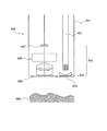
本実施形態の撮像装置では、更に、照明部と、結像光学系の物体側に配置されたカバー部と、を有することが好ましい。 The image pickup apparatus of the present embodiment further preferably has an illumination unit and a cover unit arranged on the object side of the imaging optical system.
カバー部を配置することで、被写体と結像光学系との距離が近づきすぎないように構成でき、被写体を被写界深度内とすることに有利となる。照明部を有することで、夜間撮影や、空洞内撮影にも有利となる。 By arranging the cover portion, it is possible to configure the subject so that the distance between the subject and the imaging optical system does not become too close, which is advantageous for keeping the subject within the depth of field. Having an illumination unit is also advantageous for nighttime photography and in-cavity photography.
本実施形態の撮像装置では、カバー部が、結像光学系と照明部の双方の物体側を覆うドーム状のカバー部であることが好ましい。 In the image pickup apparatus of the present embodiment, it is preferable that the cover portion is a dome-shaped cover portion that covers both the object side of the imaging optical system and the illumination unit.
このようにすることで、被写体と照明部との距離が近づき過ぎないように構成でき、撮影画像の白とびを軽減できる。 By doing so, it is possible to configure the subject so that the distance between the subject and the illumination unit does not become too close, and it is possible to reduce overexposure of the captured image.
本実施形態の光学装置は、上記の撮像装置と、照明部と、を有することを特徴とする。 The optical device of the present embodiment is characterized by having the above-mentioned imaging device and an illumination unit.
各実施形態の撮像装置は小型であるので、光学装置を小型化することができる。 Since the imaging device of each embodiment is small, the optical device can be miniaturized.
本実施形態の光学装置は、結像光学系及び照明部の物体側に配置されたドーム状カバー部と、を有することが好ましい。 The optical device of the present embodiment preferably has an imaging optical system and a dome-shaped cover portion arranged on the object side of the illumination portion.
このようにすることで、光学装置をカプセル内視鏡として使用することができる。 By doing so, the optical device can be used as a capsule endoscope.
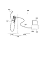
本実施形態の光学装置は、貫通孔が形成された挿入部を備え、挿入部の長さは貫通孔の直径に比べて長く、貫通孔内に、結像光学系と照明部が配置されていることが好ましい。 The optical device of the present embodiment includes an insertion portion in which a through hole is formed, the length of the insertion portion is longer than the diameter of the through hole, and the imaging optical system and the illumination unit are arranged in the through hole. It is preferable to have.
このようにすることで、光学装置を軟性内視鏡や硬性内視鏡として使用することができる。 By doing so, the optical device can be used as a flexible endoscope or a rigid endoscope.
本実施形態の光学装置では、挿入部は、並列に配置された2つの結像光学系を有し、2つの結像光学系は、所定の間隔で配置され、所定の間隔は視差が生じる間隔に設定されていることが好ましい。 In the optical device of the present embodiment, the insertion portion has two imaging optical systems arranged in parallel, the two imaging optical systems are arranged at predetermined intervals, and the predetermined intervals are intervals at which parallax occurs. It is preferable that it is set to.
このようにすることで、立体視が可能な光学装置を実現することができる。 By doing so, it is possible to realize an optical device capable of stereoscopic viewing.
以下に、本発明のある態様に係る撮像装置、カプセル内視鏡の実施例を、図面に基づいて詳細に説明する。なお、この実施例によりこの発明が限定されるものではない。 Hereinafter, examples of an imaging device and a capsule endoscope according to an aspect of the present invention will be described in detail with reference to the drawings. The present invention is not limited to this embodiment.
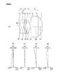
断面図について説明する。図1〜7において、(a)はレンズ断面を示している。 A cross-sectional view will be described. In FIGS. 1 to 7, (a) shows a lens cross section.
収差図について説明する。図1〜7において、(b)は球面収差(SA)、(c)は非点収差(AS)、(d)は歪曲収差(DT)、(e)は倍率色収差(CC)を示している。 The aberration diagram will be described. In FIGS. 1 to 7, (b) shows spherical aberration (SA), (c) shows astigmatism (AS), (d) shows distortion (DT), and (e) shows chromatic aberration of magnification (CC). ..
実施例1の撮像装置の結像光学系は、物体側から順に、物体側に凸面を向けた負メニスカスレンズL1と、物体側に凸面を向けた負メニスカスレンズL2と、両凸正レンズL3と、で構成されている。負メニスカスレンズL1、負メニスカスレンズL2及び両凸正レンズL3は接合されている。 The imaging optical system of the imaging apparatus of the first embodiment includes a negative meniscus lens L1 having a convex surface facing the object side, a negative meniscus lens L2 having a convex surface facing the object side, and a biconvex positive lens L3 in order from the object side. It is composed of ,. The negative meniscus lens L1, the negative meniscus lens L2, and the biconvex positive lens L3 are joined.
負メニスカスレンズL2の物体側面に、明るさ絞りSが配置されている。負メニスカスレンズL2は、負メニスカスレンズL1と接合されている。よって、明るさ絞りSは、接合面上に形成されている。より具体的には、接合面の面頂から周辺に向かって、開口部と遮光部が形成されている。受光面(撮像面)Iは球面で、物体側に凹状に湾曲している。 A brightness diaphragm S is arranged on the side surface of the object of the negative meniscus lens L2. The negative meniscus lens L2 is joined to the negative meniscus lens L1. Therefore, the brightness diaphragm S is formed on the joint surface. More specifically, an opening and a light-shielding portion are formed from the top of the joint surface to the periphery. The light receiving surface (imaging surface) I is a spherical surface and is curved in a concave shape toward the object side.
非球面は、負メニスカスレンズL1の物体側面と、負メニスカスレンズL1と負メニスカスレンズL2の接合面と、負メニスカスレンズL2と両凸正レンズL3との接合面と、両凸正レンズL3の像側面との4面に設けられている。 The aspherical surface is an image of the object side surface of the negative meniscus lens L1, the joint surface between the negative meniscus lens L1 and the negative meniscus lens L2, the joint surface between the negative meniscus lens L2 and the biconvex positive lens L3, and the biconvex positive lens L3. It is provided on four sides with the side surface.
実施例2の撮像装置の結像光学系は、物体側から順に、物体側に凸面を向けた負メニスカスレンズL1と、物体側に凸面を向けた負メニスカスレンズL2と、両凸正レンズL3と、で構成されている。負メニスカスレンズL1、負メニスカスレンズL2及び両凸正レンズL3は接合されている。 The imaging optical system of the imaging apparatus of the second embodiment includes a negative meniscus lens L1 having a convex surface facing the object side, a negative meniscus lens L2 having a convex surface facing the object side, and a biconvex positive lens L3 in order from the object side. It is composed of ,. The negative meniscus lens L1, the negative meniscus lens L2, and the biconvex positive lens L3 are joined.
負メニスカスレンズL2の像側面に、明るさ絞りSが配置されている。負メニスカスレンズL2は、負メニスカスレンズL1と接合されている。よって、明るさ絞りSは、接合面上に形成されている。より具体的には、接合面の面頂から周辺に向かって、開口部と遮光部が形成されている。受光面(撮像面)Iは球面で、物体側に凹状に湾曲している。 A brightness diaphragm S is arranged on the image side surface of the negative meniscus lens L2. The negative meniscus lens L2 is joined to the negative meniscus lens L1. Therefore, the brightness diaphragm S is formed on the joint surface. More specifically, an opening and a light-shielding portion are formed from the top of the joint surface to the periphery. The light receiving surface (imaging surface) I is a spherical surface and is curved in a concave shape toward the object side.
非球面は、負メニスカスレンズL1の物体側面と、負メニスカスレンズL1と負メニスカスレンズL2の接合面と、負メニスカスレンズL2と両凸正レンズL3との接合面と、両凸正レンズL3の像側面との4面に設けられている。 The aspherical surface is an image of the object side surface of the negative meniscus lens L1, the joint surface between the negative meniscus lens L1 and the negative meniscus lens L2, the joint surface between the negative meniscus lens L2 and the biconvex positive lens L3, and the biconvex positive lens L3. It is provided on four sides with the side surface.
実施例3の撮像装置の結像光学系は、物体側から順に、物体側に凸面を向けた負メニスカスレンズL1と、物体側に凸面を向けた正メニスカスレンズL2と、両凸正レンズL3と、で構成されている。負メニスカスレンズL1、正メニスカスレンズL2及び両凸正レンズL3は接合されている。 The imaging optical system of the imaging apparatus of the third embodiment includes a negative meniscus lens L1 having a convex surface facing the object side, a positive meniscus lens L2 having a convex surface facing the object side, and a biconvex positive lens L3 in order from the object side. It is composed of ,. The negative meniscus lens L1, the positive meniscus lens L2, and the biconvex positive lens L3 are joined.
正メニスカスレンズL2の物体側面に、明るさ絞りSが配置されている。正メニスカスレンズL2は、負メニスカスレンズL1と接合されている。よって、明るさ絞りSは、接合面上に形成されている。より具体的には、接合面の面頂から周辺に向かって、開口部と遮光部が形成されている。受光面(撮像面)Iは球面で、物体側に凹状に湾曲している。 A brightness diaphragm S is arranged on the side surface of the object of the positive meniscus lens L2. The positive meniscus lens L2 is joined to the negative meniscus lens L1. Therefore, the brightness diaphragm S is formed on the joint surface. More specifically, an opening and a light-shielding portion are formed from the top of the joint surface to the periphery. The light receiving surface (imaging surface) I is a spherical surface and is curved in a concave shape toward the object side.
非球面は、負メニスカスレンズL1の物体側面と、負メニスカスレンズL1と正メニスカスレンズL2の接合面と、正メニスカスレンズL2と両凸正レンズL3との接合面と、両凸正レンズL3の像側面との4面に設けられている。 The aspherical surface is an image of the object side surface of the negative meniscus lens L1, the joint surface between the negative meniscus lens L1 and the positive meniscus lens L2, the joint surface between the positive meniscus lens L2 and the biconvex positive lens L3, and the biconvex positive lens L3. It is provided on four sides with the side surface.
実施例4の撮像装置の結像光学系は、物体側から順に、物体側に凸面を向けた負メニスカスレンズL1と、物体側に凸面を向けた正メニスカスレンズL2と、両凸正レンズL3と、で構成されている。負メニスカスレンズL1、正メニスカスレンズL2及び両凸正レンズL3は接合されている。 The imaging optical system of the imaging apparatus of the fourth embodiment includes a negative meniscus lens L1 having a convex surface facing the object side, a positive meniscus lens L2 having a convex surface facing the object side, and a biconvex positive lens L3 in order from the object side. It is composed of ,. The negative meniscus lens L1, the positive meniscus lens L2, and the biconvex positive lens L3 are joined.
正メニスカスレンズL2の像側面に、明るさ絞りSが配置されている。正メニスカスレンズL2は、負メニスカスレンズL1と接合されている。よって、明るさ絞りSは、接合面上に形成されている。より具体的には、接合面の面頂から周辺に向かって、開口部と遮光部が形成されている。受光面(撮像面)Iは球面で、物体側に凹状に湾曲している。 A brightness diaphragm S is arranged on the image side surface of the positive meniscus lens L2. The positive meniscus lens L2 is joined to the negative meniscus lens L1. Therefore, the brightness diaphragm S is formed on the joint surface. More specifically, an opening and a light-shielding portion are formed from the top of the joint surface to the periphery. The light receiving surface (imaging surface) I is a spherical surface and is curved in a concave shape toward the object side.
非球面は、負メニスカスレンズL1の物体側面と、負メニスカスレンズL1と正メニスカスレンズL2の接合面と、正メニスカスレンズL2と両凸正レンズL3との接合面と、両凸正レンズL3の像側面との4面に設けられている。 The aspherical surface is an image of the object side surface of the negative meniscus lens L1, the joint surface between the negative meniscus lens L1 and the positive meniscus lens L2, the joint surface between the positive meniscus lens L2 and the biconvex positive lens L3, and the biconvex positive lens L3. It is provided on four sides with the side surface.
実施例5の撮像装置の結像光学系は、物体側から順に、物体側に凸面を向けた負メニスカスレンズL1と、物体側に凸面を向けた正メニスカスレンズL2と、両凸正レンズL3と、で構成されている。負メニスカスレンズL1、正メニスカスレンズL2及び両凸正レンズL3は接合されている。 The imaging optical system of the imaging apparatus of the fifth embodiment includes a negative meniscus lens L1 having a convex surface facing the object side, a positive meniscus lens L2 having a convex surface facing the object side, and a biconvex positive lens L3 in order from the object side. It is composed of ,. The negative meniscus lens L1, the positive meniscus lens L2, and the biconvex positive lens L3 are joined.
正メニスカスレンズL2の像側面に、明るさ絞りSが配置されている。正メニスカスレンズL2は、負メニスカスレンズL1と接合されている。よって、明るさ絞りSは、接合面上に形成されている。より具体的には、接合面の面頂から周辺に向かって、開口部と遮光部が形成されている。受光面(撮像面)Iは球面で、物体側に凹状に湾曲している。 A brightness diaphragm S is arranged on the image side surface of the positive meniscus lens L2. The positive meniscus lens L2 is joined to the negative meniscus lens L1. Therefore, the brightness diaphragm S is formed on the joint surface. More specifically, an opening and a light-shielding portion are formed from the top of the joint surface to the periphery. The light receiving surface (imaging surface) I is a spherical surface and is curved in a concave shape toward the object side.
非球面は、負メニスカスレンズL1の物体側面と、負メニスカスレンズL1と正メニスカスレンズL2の接合面と、正メニスカスレンズL2と両凸正レンズL3との接合面と、両凸正レンズL3の像側面との4面に設けられている。 The aspherical surface is an image of the object side surface of the negative meniscus lens L1, the joint surface between the negative meniscus lens L1 and the positive meniscus lens L2, the joint surface between the positive meniscus lens L2 and the biconvex positive lens L3, and the biconvex positive lens L3. It is provided on four sides with the side surface.
実施例6の撮像装置の結像光学系は、物体側から順に、平凹負レンズL1と、物体側に凸面を向けた正メニスカスレンズL2と、両凸正レンズL3と、で構成されている。平凹負レンズL1、正メニスカスレンズL2及び両凸正レンズL3は接合されている。 The imaging optical system of the image pickup apparatus of the sixth embodiment is composed of a plano-concave negative lens L1, a positive meniscus lens L2 with a convex surface facing the object side, and a biconvex positive lens L3 in order from the object side. .. The plano-concave negative lens L1, the positive meniscus lens L2, and the biconvex positive lens L3 are joined.
正メニスカスレンズL2の像側面に、明るさ絞りSが配置されている。正メニスカスレンズL2は、平凹負レンズL1と接合されている。よって、明るさ絞りSは、接合面上に形成されている。より具体的には、接合面の面頂から周辺に向かって、開口部と遮光部が形成されている。受光面(撮像面)Iは球面で、物体側に凹状に湾曲している。 A brightness diaphragm S is arranged on the image side surface of the positive meniscus lens L2. The positive meniscus lens L2 is joined to the planing negative lens L1. Therefore, the brightness diaphragm S is formed on the joint surface. More specifically, an opening and a light-shielding portion are formed from the top of the joint surface to the periphery. The light receiving surface (imaging surface) I is a spherical surface and is curved in a concave shape toward the object side.
非球面は、平凹負レンズL1と正メニスカスレンズL2の接合面と、正メニスカスレンズL2と両凸正レンズL3との接合面と、両凸正レンズL3の像側面との3面に設けられている。 The aspherical surface is provided on three surfaces: a junction surface between the plano-concave negative lens L1 and the positive meniscus lens L2, a junction surface between the positive meniscus lens L2 and the biconvex positive lens L3, and an image side surface of the biconvex positive lens L3. ing.
実施例7の撮像装置の結像光学系は、物体側から順に、物体側に凸面を向けた負メニスカスレンズL1と、物体側に凸面を向けた正メニスカスレンズL2と、両凸正レンズL3と、で構成されている。負メニスカスレンズL1、正メニスカスレンズL2及び両凸正レンズL3は接合されている。 The imaging optical system of the imaging apparatus of the seventh embodiment includes a negative meniscus lens L1 having a convex surface facing the object side, a positive meniscus lens L2 having a convex surface facing the object side, and a biconvex positive lens L3 in order from the object side. It is composed of ,. The negative meniscus lens L1, the positive meniscus lens L2, and the biconvex positive lens L3 are joined.
正メニスカスレンズL2の像側面に、明るさ絞りSが配置されている。正メニスカスレンズL2は、負メニスカスレンズL1と接合されている。よって、明るさ絞りSは、接合面上に形成されている。より具体的には、接合面の面頂から周辺に向かって、開口部と遮光部が形成されている。受光面(撮像面)Iは球面で、物体側に凹状に湾曲している。 A brightness diaphragm S is arranged on the image side surface of the positive meniscus lens L2. The positive meniscus lens L2 is joined to the negative meniscus lens L1. Therefore, the brightness diaphragm S is formed on the joint surface. More specifically, an opening and a light-shielding portion are formed from the top of the joint surface to the periphery. The light receiving surface (imaging surface) I is a spherical surface and is curved in a concave shape toward the object side.
非球面は、負メニスカスレンズL1の物体側面と、負メニスカスレンズL1と正メニスカスレンズL2の接合面と、正メニスカスレンズL2と両凸正レンズL3との接合面と、両凸正レンズL3の像側面との4面に設けられている。 The aspherical surface is an image of the object side surface of the negative meniscus lens L1, the joint surface between the negative meniscus lens L1 and the positive meniscus lens L2, the joint surface between the positive meniscus lens L2 and the biconvex positive lens L3, and the biconvex positive lens L3. It is provided on four sides with the side surface.
実施例8の結像光学系は、図8に示すように、物体側から順に、光学部材CGと、物体側に凸面を向けた負メニスカスレンズL1と、物体側に凸面を向けた負メニスカスレンズL2と、両凸正レンズL3と、で構成されている。負メニスカスレンズL1、負メニスカスレンズL2、明るさ絞りS及び両凸正レンズL3で構成される光学系は、実施例1の結像光学系と同じである。 As shown in FIG. 8, the imaging optical system of the eighth embodiment is, in order from the object side, an optical member CG, a negative meniscus lens L1 having a convex surface facing the object side, and a negative meniscus lens having a convex surface facing the object side. It is composed of L2 and a biconvex positive lens L3. The optical system including the negative meniscus lens L1, the negative meniscus lens L2, the brightness diaphragm S, and the biconvex positive lens L3 is the same as the imaging optical system of the first embodiment.
図8は、光学部材CGが配置できることを例示する概略図である。そのため、レンズの大きさや位置に対して、光学部材CGの大きさや位置は正確に描かれているわけではない。 FIG. 8 is a schematic view illustrating that the optical member CG can be arranged. Therefore, the size and position of the optical member CG are not accurately drawn with respect to the size and position of the lens.
光学部材CGは板状の部材で、物体側面と像側面は共に曲面になっている。図8では、物体側面と像側面は共に球面になっているので、光学部材CGの全体形状は、半球になっている。実施例8では、光学部材CGの肉厚、すなわち、物体側面と像側面との間隔は一定になっている。しかしながら、光学部材CGの肉厚は一定でなくても良い。 The optical member CG is a plate-shaped member, and both the side surface of the object and the side surface of the image are curved surfaces. In FIG. 8, since both the side surface of the object and the side surface of the image are spherical surfaces, the overall shape of the optical member CG is a hemisphere. In the eighth embodiment, the wall thickness of the optical member CG, that is, the distance between the side surface of the object and the side surface of the image is constant. However, the wall thickness of the optical member CG does not have to be constant.
また、後述のように、光学部材CGは、第1レンズの物体側面から物体側に6.0mmだけ離れた位置に配置されている。しかしながら、光学部材CGは、この位置から前後にずらした位置に配置しても良い。また、光学部材CGの曲率半径及び肉厚は一例であるので、この限りではない。 Further, as will be described later, the optical member CG is arranged at a position separated from the object side surface of the first lens by 6.0 mm on the object side. However, the optical member CG may be arranged at a position shifted back and forth from this position. Further, the radius of curvature and the wall thickness of the optical member CG are examples, and are not limited to this.
光学部材CGには、光を透過する材質が用いられている。よって、被写体からの光は光学部材CGを通過して、負メニスカスレンズL1に入射する。光学部材CGは、像側面の曲率中心が入射瞳の位置と略一致するように配置されている。よって、光学部材CGによる新たな収差は、ほとんど発生しない。すなわち、実施例8の結像光学系の結像性能は、実施例1の結像光学系の結像性能と変わらない。 A material that transmits light is used for the optical member CG. Therefore, the light from the subject passes through the optical member CG and is incident on the negative meniscus lens L1. The optical member CG is arranged so that the center of curvature on the side surface of the image substantially coincides with the position of the entrance pupil. Therefore, new aberration due to the optical member CG hardly occurs. That is, the imaging performance of the imaging optical system of Example 8 is the same as the imaging performance of the imaging optical system of Example 1.
光学部材CGは、カバーガラスとして機能する。この場合、光学部材CGは、例えば、カプセル内視鏡の外装部に設けられた観察窓に該当する。よって、実施例8の結像光学系は、カプセル内視鏡の光学系に用いることができる。実施例1〜7の結像光学系もカプセル内視鏡の光学系に用いることができる。 The optical member CG functions as a cover glass. In this case, the optical member CG corresponds to, for example, an observation window provided on the exterior portion of the capsule endoscope. Therefore, the imaging optical system of Example 8 can be used for the optical system of the capsule endoscope. The imaging optical systems of Examples 1 to 7 can also be used for the optical system of the capsule endoscope.
以下に、上記各実施例の数値データを示す。面データにおいて、rは各レンズ面の曲率半径、dは各レンズ面間の間隔、ndは各レンズのd線の屈折率、νdは各レンズのアッベ数、*印は非球面、絞りは明るさ絞りである。 The numerical data of each of the above examples is shown below. In the surface data, r is the radius of curvature of each lens surface, d is the distance between each lens surface, nd is the refractive index of the d line of each lens, νd is the Abbe number of each lens, * mark is an aspherical surface, and the aperture is bright. It is a squeeze.
また、各種データにおいて、fは全系の焦点距離、FNO.はFナンバー、ωは半画角、IHは像高である。 Further, in various data, f is the focal length of the entire system, FNO. Is the F number, ω is the half angle of view, and IH is the image height.
また、実施例8は、実施例1の結像光学系の物体側に光学部材CGを配置したものである。実施例8の面データにおいて、C1は光学部材CGの物体側面、C2は光学部材CGの像側面を示す。また、実施例8の非球面データと各種データは、実施例1の非球面データや各種データと同じであるので記載は省略する。 Further, in the eighth embodiment, the optical member CG is arranged on the object side of the imaging optical system of the first embodiment. In the surface data of the eighth embodiment, C1 indicates an object side surface of the optical member CG, and C2 indicates an image side surface of the optical member CG. Further, since the aspherical data and various data of Example 8 are the same as the aspherical data and various data of Example 1, the description thereof will be omitted.
また、非球面形状は、光軸方向をz、光軸に直交する方向をyにとり、円錐係数をk、非球面係数をA4、A6、A8、A10、A12…としたとき、次の式で表される。
z=(y2/r)/[1+{1−(1+k)(y/r)2}1/2]
+A4y4+A6y6+A8y8+A10y10+A12y12+…
また、非球面係数において、「e−n」(nは整数)は、10のn乗を示している。なお、これら諸元値の記号は後述の実施例の数値データにおいても共通である。
The aspherical shape has the following equation when the optical axis direction is z, the direction orthogonal to the optical axis is y, the conical coefficient is k, and the aspherical coefficient is A4, A6, A8, A10, A12, and so on. expressed.
z = (y 2 / r) / [1 + {1- (1 + k) (y / r) 2 } 1/2 ]
+ A4y 4 + A6y 6 + A8y 8 + A10y 10 + A12y 12 + ...
Further, in the aspherical coefficient, "en" (n is an integer) indicates 10 to the nth power. The symbols of these specification values are also common to the numerical data of the examples described later.
数値実施例1
単位 mm
面データ
面番号 r d nd νd
物体面 ∞ 10.00
1* 3.915 0.30 1.51633 64.14
2(絞り) ∞ 0.00
3* 0.341 0.08 1.63387 23.38
4* 0.264 0.38 1.59201 67.02
5* -0.541 0.10
6 ∞ 0.50 1.51633 64.14
7 ∞ 0.32
像面 -1.021
非球面データ
第1面
k=0.000
A4=1.01078e-02,A6=3.57526e-01
第3面
k=0.000
A4=-1.50834e+01,A6=-8.56121e+01,A8=2.20481e+03
第4面
k=0.000
A4=-1.50424e+01,A6=1.11831e+01,A8=-1.73879e+03
第5面
k=0.000
A4=-1.09574e-01,A6=8.90158e-01,A8=-2.24239e+01,
A10=1.37860e+02
各種データ
f 0.78
FNO. 2.86
2ω 140.00
IH 0.73
Numerical Example 1
Unit mm
Surface data Surface number rd nd ν d
Object surface ∞ 10.00
1 * 3.915 0.30 1.51633 64.14
2 (Aperture) ∞ 0.00
3 * 0.341 0.08 1.63387 23.38
4 * 0.264 0.38 1.59201 67.02
5 * -0.541 0.10
6 ∞ 0.50 1.51633 64.14
7 ∞ 0.32
Image plane -1.021
First surface of aspherical data
k = 0.000
A4 = 1.01078e-02, A6 = 3.57526e-01
Third side
k = 0.000
A4 = -1.50834e + 01, A6 = -8.56121e + 01, A8 = 2.20481e + 03
Fourth side
k = 0.000
A4 = -1.50424e + 01, A6 = 1.11831e + 01, A8 = -1.73879e + 03
Side 5
k = 0.000
A4 = -1.09574e-01, A6 = 8.90158e-01, A8 = -2.24239e + 01,
A10 = 1.37860e + 02
Various data f 0.78
FNO. 2.86
2ω 140.00
IH 0.73
数値実施例2
単位 mm
面データ
面番号 r d nd νd
物体面 ∞ 10.00
1* 4.119 0.30 1.51633 64.14
2* 0.336 0.09 1.63387 23.38
3(絞り) ∞ 0.00
4* 0.273 0.38 1.59201 67.02
5* -0.544 0.10
6 ∞ 0.50 1.51633 64.14
7 ∞ 0.32
像面 -1.010
非球面データ
第1面
k=0.000
A4=9.12915e-02,A6=7.41213e-02
第2面
k=0.000
A4=-1.28745e+01,A6=-1.27825e+02,A8=1.07474e+03
第4面
k=0.000
A4=-7.32807e+00,A6=-1.28401e+01,A8=-3.30868e+03
第5面
k=0.000
A4=-2.38483e-01,A6=7.37942e-01,A8=-1.97726e+01,
A10=9.25956e+01
各種データ
f 0.79
FNO. 2.85
2ω 140.00
IH 0.73
Numerical Example 2
Unit mm
Surface data Surface number rd nd ν d
Object surface ∞ 10.00
1 * 4.119 0.30 1.51633 64.14
2 * 0.336 0.09 1.63387 23.38
3 (Aperture) ∞ 0.00
4 * 0.273 0.38 1.59201 67.02
5 * -0.544 0.10
6 ∞ 0.50 1.51633 64.14
7 ∞ 0.32
Image plane -1.010
First surface of aspherical data
k = 0.000
A4 = 9.12915e-02, A6 = 7.41213e-02
Second side
k = 0.000
A4 = -1.28745e + 01, A6 = -1.27825e + 02, A8 = 1.07474e + 03
Fourth side
k = 0.000
A4 = -7.32807e + 00, A6 = -1.28401e + 01, A8 = -3.30868e + 03
Side 5
k = 0.000
A4 = -2.38843e-01, A6 = 7.37742e-01, A8 = -1.97726e + 01,
A10 = 9.29556e + 01
Various data f 0.79
FNO. 2.85
2ω 140.00
IH 0.73
数値実施例3
単位 mm
面データ
面番号 r d nd νd
物体面 ∞ 10.00
1* 5.478 0.30 1.51633 64.14
2(絞り) ∞ 0.00
3* 0.339 0.11 1.63387 23.38
4* 0.421 0.38 1.59201 67.02
5* -0.558 0.10
6 ∞ 0.50 1.51633 64.14
7 ∞ 0.32
像面 -1.043
非球面データ
第1面
k=0.000
A4=-2.73993e-02,A6=3.59800e-01
第3面
k=0.000
A4=-7.34591e+00,A6=-1.35791e+02,A8=1.25398e+03
第4面
k=0.000
A4=1.12022e+01,A6=-2.39954e+02,A8=1.34059e+03
第5面
k=0.000
A4=-2.13402e-01,A6=2.46455e+00,A8=-2.31632e+01,
A10=3.21745e+01
各種データ
f 0.79
FNO. 2.90
2ω 140.00
IH 0.73
Numerical Example 3
Unit mm
Surface data Surface number rd nd ν d
Object surface ∞ 10.00
1 * 5.478 0.30 1.51633 64.14
2 (Aperture) ∞ 0.00
3 * 0.339 0.11 1.63387 23.38
4 * 0.421 0.38 1.59201 67.02
5 * -0.558 0.10
6 ∞ 0.50 1.51633 64.14
7 ∞ 0.32
Image plane -1.043
First surface of aspherical data
k = 0.000
A4 = -2.73993e-02, A6 = 3.59800e-01
Third side
k = 0.000
A4 = -7.34591e + 00, A6 = -1.35791e + 02, A8 = 1.25398e + 03
Fourth side
k = 0.000
A4 = 1.12022e + 01, A6 = -2.39954e + 02, A8 = 1.34059e + 03
Side 5
k = 0.000
A4 = -2.13402e-01, A6 = 2.46455e + 00, A8 = -2.31632e + 01,
A10 = 3.21745e + 01
Various data f 0.79
FNO. 2.90
2ω 140.00
IH 0.73
数値実施例4
単位 mm
面データ
面番号 r d nd νd
物体面 ∞ 10.00
1* 5.245 0.30 1.51633 64.14
2* 0.339 0.12 1.63387 23.38
3(絞り) ∞ 0.00
4* 0.408 0.38 1.59201 67.02
5* -0.559 0.10
6 ∞ 0.50 1.51633 64.14
7 ∞ 0.32
像面 -1.045
非球面データ
第1面
k=0.000
A4=-1.65174e-03,A6=1.05156e-01
第2面
k=0.000
A4=-7.06981e+00,A6=-3.94640e+01,A8=-2.78628e+02
第4面
k=0.000
A4=1.61345e+01,A6=-2.05251e+02,A8=3.98054e+03
第5面
k=0.000
A4=-3.01045e-01,A6=1.57960e+00,A8=-2.81214e+01,
A10=3.76612e-01
各種データ
f 0.79
FNO. 2.89
2ω 140.00
IH 0.73
Numerical Example 4
Unit mm
Surface data Surface number rd nd ν d
Object surface ∞ 10.00
1 * 5.245 0.30 1.51633 64.14
2 * 0.339 0.12 1.63387 23.38
3 (Aperture) ∞ 0.00
4 * 0.408 0.38 1.59201 67.02
5 * -0.559 0.10
6 ∞ 0.50 1.51633 64.14
7 ∞ 0.32
Image plane -1.045
First surface of aspherical data
k = 0.000
A4 = -1.65174e-03, A6 = 1.05156e-01
Second side
k = 0.000
A4 = -7.06981e + 00, A6 = -3.94640e + 01, A8 = -2.78628e + 02
Fourth side
k = 0.000
A4 = 1.61345e + 01, A6 = -2.05251e + 02, A8 = 3.98054e + 03
Side 5
k = 0.000
A4 = -3.01045e-01, A6 = 1.57960e + 00, A8 = -2.81214e + 01,
A10 = 3.76612e-01
Various data f 0.79
FNO. 2.89
2ω 140.00
IH 0.73
数値実施例5
単位 mm
面データ
面番号 r d nd νd
物体面 ∞ 10.00
1* 1.711 0.30 1.53367 55.82
2* 0.249 0.06 1.63387 23.38
3(絞り) ∞ 0.00
4* 0.232 0.37 1.53367 55.82
5* -0.440 0.10
6 ∞ 0.30 1.51633 64.14
7 ∞ 0.40
像面 -0.903
非球面データ
第1面
k=0.000
A4=1.90268e-01,A6=2.04812e-01
第2面
k=0.000
A4=-4.45853e+01
第4面
k=0.000
A4=-2.75086e+01
第5面
k=0.000
A4=-2.20911e-01,A6=-2.49190e+00
各種データ
f 0.76
FNO. 2.89
2ω 140.00
IH 0.73
Numerical Example 5
Unit mm
Surface data Surface number rd nd ν d
Object surface ∞ 10.00
1 * 1.711 0.30 1.53367 55.82
2 * 0.249 0.06 1.63387 23.38
3 (Aperture) ∞ 0.00
4 * 0.232 0.37 1.53367 55.82
5 * -0.440 0.10
6 ∞ 0.30 1.51633 64.14
7 ∞ 0.40
Image plane -0.903
First surface of aspherical data
k = 0.000
A4 = 1.90268e-01, A6 = 2.04812e-01
Second side
k = 0.000
A4 = -4.45853e + 01
Fourth side
k = 0.000
A4 = -2.75086e + 01
Side 5
k = 0.000
A4 = -2.20911e-01, A6 = -2.49190e + 00
Various data f 0.76
FNO. 2.89
2ω 140.00
IH 0.73
数値実施例6
単位 mm
面データ
面番号 r d nd νd
物体面 ∞ 10.00
1 ∞ 0.30 1.51633 64.14
2* 0.320 0.15 1.63387 23.38
3(絞り) ∞ 0.00
4* 0.359 0.38 1.59201 67.02
5* -0.553 0.10
6 ∞ 0.50 1.51633 64.14
7 ∞ 0.32
像面 -1.264
非球面データ
第2面
k=0.000
A4=-2.39160e+00,A6=-1.64025e+02,A8=1.78226e+03
第4面
k=0.000
A4=2.44268e+01,A6=-4.18708e-01,A8=-6.12781e+03
第5面
k=0.000
A4=-2.47671e-01,A6=-2.58386e+00,A8=-1.34562e+00,
A10=-4.60865e+02
各種データ
f 0.81
FNO. 3.03
2ω 140.00
IH 0.73
Numerical Example 6
Unit mm
Surface data Surface number rd nd ν d
Object surface ∞ 10.00
1 ∞ 0.30 1.51633 64.14
2 * 0.320 0.15 1.63387 23.38
3 (Aperture) ∞ 0.00
4 * 0.359 0.38 1.59201 67.02
5 * -0.553 0.10
6 ∞ 0.50 1.51633 64.14
7 ∞ 0.32
Image plane -1.264
Second surface of aspherical data
k = 0.000
A4 = -2.39160e + 00, A6 = -1.64025e + 02, A8 = 1.78226e + 03
Fourth side
k = 0.000
A4 = 2.44268e + 01, A6 = -4.18708e-01, A8 = -6.12781e + 03
Side 5
k = 0.000
A4 = -2.47671e-01, A6 = -2.58386e + 00, A8 = -1.34562e + 00,
A10 = -4.60865e + 02
Various data f 0.81
FNO. 3.03
2ω 140.00
IH 0.73
数値実施例7
単位 mm
面データ
面番号 r d nd νd
物体面 ∞ 10.00
1* 3.940 0.30 1.51633 64.14
2* 0.312 0.11 1.63387 23.38
3(絞り) ∞ 0.00
4* 0.345 0.36 1.59201 67.02
5* -0.535 0.10
6 ∞ 0.30 1.51633 64.14
7 ∞ 0.40
像面 -0.963
非球面データ
第1面
k=0.000
A4=-1.59904e-01,A6=1.67922e-01
第2面
k=0.000
A4=-9.76312e+00,A6=4.40264e+01,A8=-1.53642e+03
第4面
k=0.000
A4=1.39889e+01,A6=-2.57438e+01,A8=-3.08758e+02
第5面
k=0.000
A4=-2.85173e-01,A6=1.46899e+00,A8=-3.49420e+01,
A10=-1.62304e+02
各種データ
f 0.75
FNO. 2.95
2ω 169.99
IH 0.73
Numerical Example 7
Unit mm
Surface data Surface number rd nd ν d
Object surface ∞ 10.00
1 * 3.940 0.30 1.51633 64.14
2 * 0.312 0.11 1.63387 23.38
3 (Aperture) ∞ 0.00
4 * 0.345 0.36 1.59201 67.02
5 * -0.535 0.10
6 ∞ 0.30 1.51633 64.14
7 ∞ 0.40
Image plane -0.963
First surface of aspherical data
k = 0.000
A4 = -1.59904e-01, A6 = 1.67922e-01
Second side
k = 0.000
A4 = -9.76312e + 00, A6 = 4.40264e + 01, A8 = -1.53642e + 03
Fourth side
k = 0.000
A4 = 1.39889e + 01, A6 = -2.57438e + 01, A8 = -3.08758e + 02
Side 5
k = 0.000
A4 = -2.85173e-01, A6 = 1.46899e + 00, A8 = -3.49420e + 01,
A10 = -1.62304e + 02
Various data f 0.75
FNO. 2.95
2ω 169.99
IH 0.73
数値実施例8
単位 mm
面データ
面番号 r d nd νd
物面 ∞ 3.50
C1 8.500 0.50 1.5896 30.00
C2 8.000 6.00
1* 3.915 0.30 1.51633 64.14
2(絞り) ∞ 0.00
3* 0.341 0.08 1.63387 23.38
4* 0.264 0.38 1.59201 67.02
5* -0.541 0.10
6 ∞ 0.50 1.51633 64.14
7 ∞ 0.32
像面 -1.021
Numerical Example 8
Unit mm
Surface data Surface number rd nd ν d
Physical surface ∞ 3.50
C1 8.500 0.50 1.5896 30.00
C2 8.000 6.00
1 * 3.915 0.30 1.51633 64.14
2 (Aperture) ∞ 0.00
3 * 0.341 0.08 1.63387 23.38
4 * 0.264 0.38 1.59201 67.02
5 * -0.541 0.10
6 ∞ 0.50 1.51633 64.14
7 ∞ 0.32
Image plane -1.021
次に、各実施例における条件式の値を以下に掲げる。
実施例1 実施例2 実施例3
(1)|Θout60/60°| 0.64 0.70 0.61
(2)|PS×Rimg| 0.87 0.86 0.87
(3)|EXP/Rimg| 1.15 1.06 1.15
(4)|R1R/R1L| 0.09 0.08 0.06
(5)R1R/f 0.43 0.43 0.43
(6)|SAGs1/TL| 0.001 0.003 0.001
(7)THI2/TL 0.05 0.06 0.07
(8)(R3L+R3R)/(R3L-R3R) -0.34 -0.33 -0.14
(9)|Θout60/Θimg60| 0.91 1.00 0.90
実施例4 実施例5 実施例6
(1)|Θout60/60°| 0.70 0.73 0.66
(2)|PS×Rimg| 0.87 0.89 0.98
(3)|EXP/Rimg| 1.02 1.15 0.85
(4)|R1R/R1L| 0.06 0.15 0.00
(5)R1R/f 0.43 0.33 0.39
(6)|SAGs1/TL| 0.003 0.009 0.000
(7)THI2/TL 0.07 0.04 0.09
(8)(R3L+R3R)/(R3L-R3R) -0.16 -0.31 -0.21
(9)|Θout60/Θimg60| 1.03 0.91 1.22
実施例7
(1)|Θout60/60°| 0.70
(2)|PS×Rimg| 0.86
(3)|EXP/Rimg| 1.04
(4)|R1R/R1L| 0.08
(5)R1R/f 0.42
(6)|SAGs1/TL| 0.005
(7)THI2/TL 0.07
(8)(R3L+R3R)/(R3L-R3R) -0.22
(9)|Θout60/Θimg60| 1.00
Next, the values of the conditional expressions in each embodiment are listed below.
Example 1 Example 2 Example 3
(1) | Θout60 / 60 ° | 0.64 0.70 0.61
(2) | PS × Rimg | 0.87 0.86 0.87
(3) | EXP / Rimg | 1.15 1.06 1.15
(4) | R1R / R1L | 0.09 0.08 0.06
(5) R1R / f 0.43 0.43 0.43
(6) | SAGs1 / TL | 0.001 0.003 0.001
(7) THI2 / TL 0.05 0.06 0.07
(8) (R3L + R3R) / (R3L-R3R) -0.34 -0.33 -0.14
(9) | Θout60 / Θimg60 | 0.91 1.00 0.90
Example 4 Example 5 Example 6
(1) | Θout60 / 60 ° | 0.70 0.73 0.66
(2) | PS × Rimg | 0.87 0.89 0.98
(3) | EXP / Rimg | 1.02 1.15 0.85
(4) | R1R / R1L | 0.06 0.15 0.00
(5) R1R / f 0.43 0.33 0.39
(6) | SAGs1 / TL | 0.003 0.009 0.000
(7) THI2 / TL 0.07 0.04 0.09
(8) (R3L + R3R) / (R3L-R3R) -0.16 -0.31 -0.21
(9) | Θout60 / Θimg60 | 1.03 0.91 1.22
Example 7
(1) | Θout60 / 60 ° | 0.70
(2) | PS × Rimg | 0.86
(3) | EXP / Rimg | 1.04
(4) | R1R / R1L | 0.08
(5) R1R / f 0.42
(6) | SAGs1 / TL | 0.005
(7) THI2 / TL 0.07
(8) (R3L + R3R) / (R3L-R3R) -0.22
(9) | Θout60 / Θimg60 | 1.00
図9は、撮像装置の例である。この例では、撮像装置はカプセル内視鏡である。カプセル内視鏡100は、カプセルカバー101と透明カバー102とを有する。カプセルカバー101と透明カバー102とによって、カプセル内視鏡100の外装部が構成されている。
FIG. 9 is an example of an imaging device. In this example, the imaging device is a capsule endoscope. The
カプセルカバー101は、略円筒形状の中央部と、略椀形状の底部と、で構成されている。透明カバー102は、中央部を挟んで、底部と対向する位置に配置されている。透明カバー102は、略椀形状の透明部材によって構成されている。カプセルカバー101と透明カバー102とは、互いに水密的に連設されている。
The
カプセル内視鏡100の内部には、結像光学系103と、照明部104と、撮像素子105と、駆動制御部106と、信号処理部107と、を備えている。なお、図示しないが、カプセル内視鏡100の内部には、受電手段と送信手段が設けられている。
Inside the
照明部104からは、照明光が出射する。照明光は透明カバー102を通過して、被写体に照射される。被写体からの光は、結像光学系103に入射する。結像光学系103によって、像位置に被写体の光学像が形成される。
Illumination light is emitted from the
光学像は、撮像素子105で撮像される。撮像素子105の駆動と制御は、駆動制御部106で行われる。また、撮像素子105からの出力信号は、必要に応じて、信号処理部107で処理される。
The optical image is imaged by the
ここで、結像光学系103には、例えば、上述の実施例1の結像光学系が用いられている。このように、結像光学系103は、小型でありながら、広い画角と小さいFナンバーを有する。よって、結像光学系103では、高い解像度を有する広角な光学像が得られる。
Here, for the imaging
また、カプセル内視鏡100は、小型でありながら長いバックフォーカスを有し、良好な像が結像できる光学系を備えている。よって、カプセル内視鏡100では、小型でありながら、高解像な画像が得られる。
Further, the
なお、ここでは撮像素子が湾曲した受光面を有しているが、撮像素子の受光面は平坦であっても、像を受ける面が湾曲していれば、その面を湾曲した受光面ということができる。このような例として、平坦な受光面を持つ撮像素子の受光面上にファイバ束を配置してその一端面を湾曲した形状に加工し、その湾曲した端面で物体像を受ける構成が考えられる。 Although the image sensor has a curved light receiving surface here, even if the light receiving surface of the image sensor is flat, if the surface receiving the image is curved, that surface is a curved light receiving surface. Can be done. As such an example, a configuration is conceivable in which a fiber bundle is arranged on a light receiving surface of an image sensor having a flat light receiving surface, one end surface thereof is processed into a curved shape, and an object image is received by the curved end surface.
図10は、撮像装置の別の例である。この例では、撮像装置は車載カメラである。図10(a)は車外に車載カメラを搭載した例を示す図である。図10(b)は、車内に車載カメラを搭載した例を示す図である。 FIG. 10 is another example of the imaging device. In this example, the imaging device is an in-vehicle camera. FIG. 10A is a diagram showing an example in which an in-vehicle camera is mounted outside the vehicle. FIG. 10B is a diagram showing an example in which an in-vehicle camera is mounted in the vehicle.
図10(a)に示すように、車載カメラ201は、自動車200のフロントグリルに設けられている。車載カメラ201は、結像光学系と撮像素子を備えている。車載カメラ201の結像光学系には、例えば、上述の実施例1の結像光学系が用いられている。よって、良好な光学像が形成される。
As shown in FIG. 10A, the vehicle-mounted
図10(b)に示すように、車載カメラ201は、自動車200の天井近傍に設けられている。車載カメラ201の作用効果は、既に説明したとおりである。車載カメラ201では、小型でありながら、高解像な画像が得られる。
As shown in FIG. 10B, the vehicle-mounted
図11は、撮像装置の別の例である。この例では、撮像装置は内視鏡システムである。図11は、内視鏡システムの概略構成を示す図である。 FIG. 11 is another example of the image pickup apparatus. In this example, the imaging device is an endoscopic system. FIG. 11 is a diagram showing a schematic configuration of an endoscope system.
内視鏡システム300は、電子内視鏡を用いた観察システムである。内視鏡システム300は、電子内視鏡310と画像処理装置320とから構成されている。電子内視鏡310は、スコープ部310aと接続コード部310bとを備えている。また、画像処理装置320には、表示ユニット330が接続されている。
The
スコープ部310aは、操作部340と挿入部341に大別される。挿入部341は、細長で患者の体腔内へ挿入可能になっている。また、挿入部341は、可撓性を有する部材で構成されている。観察者は、操作部340に設けられているアングルノブ等により、諸操作を行うことができる。
The
また、操作部340からは、接続コード部310bが延設されている。接続コード部310bは、ユニバーサルコード350を備えている。ユニバーサルコード350は、コネクタ360を介して画像処理装置320に接続されている。
Further, a
ユニバーサルコード350は、各種の信号等の送受信に用いられる。各種の信号としては、電源電圧信号及びCCD駆動信号等がある。これらの信号は、電源装置やビデオプロセッサからスコープ部310aに送信される。また、各種の信号として映像信号がある。この信号は、スコープ部310aからビデオプロセッサに送信される。
The
なお、画像処理装置320内のビデオプロセッサには、図示しないVTRデッキ、ビデオプリンタ等の周辺機器が接続可能である。ビデオプロセッサは、スコープ部310aからの映像信号に対して信号処理を施す。映像信号に基づいて、表示ユニット330の表示画面上に内視鏡画像が表示される。
Peripheral devices such as a VTR deck and a video printer (not shown) can be connected to the video processor in the
挿入部341の先端部342には、光学系が配置されている。図12は、内視鏡の光学系の構成を示す図である。光学系400は、照明部と観察部とを有する。
An optical system is arranged at the
照明部は、ライトガイド401と照明レンズ402とを有する。ライトガイド401は、照明光を挿入部341の先端部342に伝送する。伝送された照明光は、ライトガイド401の先端面から出射する。
The illumination unit has a
先端部342には、照明レンズ402が配置されている。照明レンズ402は、ライトガイド401の先端面と対向する位置に配置されている。照明光は照明レンズ402を通過し、照明窓403から出射する。これにより、被検体内部の観察対象部位(以下、「観察部位404」という)が照明される。
An
先端部342には、観察窓405が、照明窓403の隣に設けられている。観察部位404からの光は、観察窓405を通過して、先端部342内に入射する。観察窓405の後方には、観察部が設けられている。
An
観察部は、結像光学系406と撮像素子407とを有する。結像光学系406に、例えば、実施例1の結像光学系が用いられている。
The observation unit includes an imaging
観察部位404からの反射光は、結像光学系406を通過して撮像素子407に入射する。撮像素子407の撮像面には、観察部位404の像(光学像)が形成される。観察部位404の像は撮像素子407によって光電変換され、これにより観察部位404の画像が得られる。観察部位404の画像は表示ユニット330に表示される。このようにして、観察者は、観察部位404の画像を観察できる。
The reflected light from the
結像光学系406では、像面は湾曲形状になっている。撮像素子407は、像面の形状と同じ湾曲形状の受光面(撮像面)を有している。撮像素子407を用いることで、撮影画像の画質を向上することができる。
In the imaging
図12に示す先端部342では、結像光学系の数は1つであるため、立体視はできない。2つの結像光学系を用いることで、立体視が可能になる。
At the
図13は、立体視内視鏡の光学系の構成を示す図である。立体視内視鏡の先端部500には、結像光学系510が配置されている。先端部500には、照明光学系も配置されているが、図示を省略している。
FIG. 13 is a diagram showing a configuration of an optical system of a stereoscopic endoscope. An imaging
結像光学系510は、第1の結像光学系510Lと第2の結像光学系510Rとで構成されている。第1の結像光学系510Lと第2の結像光学系510Rは、同一の光学系である。2つの結像光学系には、例えば、実施例6の結像光学系が用いられている。
The imaging
第1の結像光学系510Lの像位置には、撮像素子520Lが配置されている。第2の結像光学系510Rの像位置には、撮像素子520Rが配置されている。
An
第1の結像光学系510Lと第2の結像光学系510Rでは、像面は、共に湾曲形状になっている。撮像素子520Lと撮像素子520Rは、像面の形状と同じ湾曲形状の受光面(撮像面)を有している。撮像素子520Lと撮像素子520Rを用いることで、撮影画像の画質を向上することができる。
In the first imaging
第1の結像光学系510Lと第2の結像光学系510Rは、並列に配置されている。よって、結像光学系510では、視差を有する一対の光学像が形成される。一方の光学像は撮像素子520Lで撮像され、他方の光学像は撮像素子520Rで撮像される。
The first imaging
撮像素子520Lから出力された画像信号と、撮像素子520Rから出力された画像信号は、画像処理装置に入力される。画像処理装置では、立体視用映像信号が生成される。立体視用映像信号は、立体視用表示モニタに入力される。
The image signal output from the
立体視用表示モニタでは、左目用の画像と右目用の画像とが、交互に表示される。立体視用メガネで2つの画像を見ることで、立体視ができる。 On the stereoscopic display monitor, the image for the left eye and the image for the right eye are displayed alternately. Stereoscopic viewing is possible by viewing two images with stereoscopic glasses.
以上のように、本発明は、小型でありながら、長いバックフォーカスを有し、良好な像を結像できる結像光学系を備えた撮像装置に適している。 As described above, the present invention is suitable for an imaging apparatus provided with an imaging optical system capable of forming a good image with a long back focus despite its small size.
L1、L2、L3 レンズ
S 明るさ絞り
I 像面
C カバーガラス
CG 光学部材
100 カプセル内視鏡
101 カプセルカバー
102 透明カバー
103 結像光学系
104 照明部
105 撮像素子
106 駆動制御部
107 信号処理部
200 自動車
201 車載カメラ
300 内視鏡システム
310 電子内視鏡
310a スコープ部
310b 接続コード部
320 画像処理装置
330 表示ユニット
340 操作部
341 挿入部
342 先端部
350 ユニバーサルコード
360 コネクタ
400 光学系
401 ライトガイド
402 照明レンズ
403 照明窓
404 観察部位
405 観察窓
406 結像光学系
407 撮像素子
500 先端部
510 結像光学系
510L 第1の結像光学系
510R 第2の結像光学系
520L、520R 撮像素子
L1, L2, L3 Lens S Brightness Aperture I Image plane C Cover glass
CG
Claims (10)
前記結像光学系の像側に配置され、前記結像光学系に向けて凹状に湾曲した非平面の受光面を有する撮像部と、を有し、
前記接合レンズは、物体側から順に、負の屈折力を有する第1レンズと、第2レンズと、正の屈折力を有する第3レンズと、からなり、
前記明るさ絞りは、前記第2レンズの物体側のレンズ面に配置されているか、又は、前記第2レンズの像側のレンズ面に配置されていることを特徴とする撮像装置。 An imaging optical system consisting of a brightness diaphragm that determines the on-axis luminous flux, a single junction lens, and
It has an imaging unit that is arranged on the image side of the imaging optical system and has a non-planar light receiving surface that is concavely curved toward the imaging optical system.
The cemented lens includes, in order from the object side, a first lens having a negative refractive power, a second lens, a third lens having a positive refractive power, Ri Tona,
The aperture stop are either disposed on the lens surface on the object side of the second lens, or an imaging apparatus characterized that you have been placed on the lens surface on the image side of the second lens.
前記結像光学系の像側に配置され、前記結像光学系に向けて凹状に湾曲した非平面の受光面を有する撮像部と、を有し、It has an imaging unit that is arranged on the image side of the imaging optical system and has a non-planar light receiving surface that is concavely curved toward the imaging optical system.
前記接合レンズは、物体側から順に、負の屈折力を有する第1レンズと、第2レンズと、正の屈折力を有する第3レンズと、からなり、The bonded lens is composed of a first lens having a negative refractive power, a second lens, and a third lens having a positive refractive power in order from the object side.
以下の条件式(8)を満足することを特徴とする撮像装置。An imaging device characterized by satisfying the following conditional expression (8).
−1<(R3L+R3R)/(R3L−R3R)<0 (8)-1 <(R3L + R3R) / (R3L-R3R) <0 (8)
ここで、here,
R3Lは、前記第3レンズの物体側のレンズ面の近軸曲率半径、R3L is the paraxial radius of curvature of the lens surface on the object side of the third lens.
R3Rは、前記第3レンズの像側のレンズ面の近軸曲率半径、R3R is the paraxial radius of curvature of the lens surface on the image side of the third lens.
である。Is.
0.4<|Θout60/60°|<1.0 (1)0.4 << | Θout60 / 60 ° | <1.0 (1)
ここで、here,
Θout60は、前記第3レンズの像側面から射出した所定の主光線と光軸とのなす角度、Θout60 is an angle formed by a predetermined main ray emitted from the image side surface of the third lens and the optical axis.
前記所定の主光線は、前記第1レンズの物体側の空間において、前記光軸とのなす角度が60°となる主光線、The predetermined main ray is a main ray having an angle of 60 ° with the optical axis in the space on the object side of the first lens.
である。Is.
0.7<|PS×Rimg|<1.5 (2)
0.7<|EXP/Rimg|<1.5 (3)
ここで、
PSは、前記結像光学系のペッツバール和であり、
前記ペッツバール和PSは、以下の式で表される。
iは、前記結像光学系中の各レンズの物体側からの順番、
kは、前記結像光学系中のレンズの総数、
n i は、i番目のレンズのd線での屈折率、
f i は、i番目のレンズのd線での焦点距離、
EXPは、前記受光面から前記結像光学系の近軸射出瞳位置までの光軸に沿った距離であり、前記近軸射出瞳位置が前記受光面よりも物体側にある場合の符号を負とし、
Rimgは、前記光軸と前記受光面とが交わる点を面頂点とし、前記面頂点と、前記結像光学系に最大画角で入射する主光線と前記受光面とが交わる点と、を含む仮想球面の曲率半径、
である。 The imaging device according to any one of claims 1 to 3, wherein the imaging device satisfies the following conditional expressions (2) and (3).
0.7 << PS x Rimg | <1.5 (2)
0.7 << | EXP / Rimg | <1.5 (3)
here,
PS is the Petzval sum of the imaging optical system.
The Petzval sum PS is represented by the following equation.
i is the order of each lens in the imaging optical system from the object side,
k is the total number of lenses in the imaging optical system,
n i is the refractive index of the i-th lens on the d line,
f i is the focal length of the i-th lens on the d line,
EXP is the distance along the optical axis from the light receiving surface to the paraxial exit pupil position of the imaging optical system, and has a negative sign when the paraxial exit pupil position is closer to the object side than the light receiving surface. age,
Rimg has a surface apex at the point where the optical axis and the light receiving surface intersect, and includes the surface apex and a point where the main light beam incident on the imaging optical system at the maximum angle of view and the light receiving surface intersect. The radius of curvature of the virtual sphere,
Is .
以下の条件式(4)、(5)を満足することを特徴とする請求項1から5のいずれか一項に記載の撮像装置。
0≦|R1R/R1L|<0.2 (4)
0.25<R1R/f<0.5 (5)
ここで、
R1Rは、前記第1レンズの像側のレンズ面の近軸曲率半径、
R1Lは、前記第1レンズの物体側のレンズ面の近軸曲率半径、
fは、前記結像光学系のd線での焦点距離、
である。 The lens surface on the image side of the first lens is a surface convex toward the object side.
The imaging device according to any one of claims 1 to 5, wherein the imaging device satisfies the following conditional expressions (4) and (5).
0 ≦ | R1R / R1L | <0.2 (4)
0.25 <R1R / f <0.5 (5)
here,
R1R is the paraxial radius of curvature of the lens surface on the image side of the first lens.
R1L is the paraxial radius of curvature of the lens surface on the object side of the first lens.
f is the focal length of the imaging optical system on the d line,
Is.
0≦|SAGs1/TL|<0.05 (6)
ここで、
SAGs1は、前記第1レンズの物体側のレンズ面の面頂点から、前記結像光学系における最大像高に入射する最周辺の有効光線が前記第1レンズの物体側のレンズ面を通過する点までの光軸に沿う方向での距離であり、光線が進む方向を符号が正となる方向とし、
TLは、前記第1レンズの物体側のレンズ面から前記受光面までの前記光軸上の距離、である。 The imaging device according to any one of claims 1 to 6, wherein the imaging device satisfies the following conditional expression (6).
0 ≦ | SAGs1 / TL | <0.05 (6)
here,
SAGs1 are points where the outermost effective light rays incident on the maximum image height in the imaging optical system pass through the lens surface on the object side of the first lens from the surface apex of the lens surface on the object side of the first lens. It is the distance along the optical axis up to, and the direction in which the light beam travels is the direction in which the sign is positive.
TL is the distance on the optical axis from the lens surface of the first lens on the object side to the light receiving surface.
以下の条件式(7)を満足することを特徴とする請求項1から7のいずれか一項に記載の撮像装置。
0.02<THI2/TL<0.2 (7)
ここで、
THI2は、光軸上での前記第2レンズの面間隔、
TLは、前記第1レンズの物体側のレンズ面から前記受光面までの前記光軸上の距離、である。 The second lens is a meniscus lens whose convexity is directed toward the object side.
The imaging apparatus according to any one of claims 1 to 7, wherein the imaging device satisfies the following conditional expression (7).
0.02 <THI2 / TL <0.2 (7)
here,
THI2 is the surface spacing of the second lens on the optical axis.
TL is the distance on the optical axis from the lens surface of the first lens on the object side to the light receiving surface.
0.7<|Θout60/Θimg60|<1.5 (9)0.7 << | Θout60 / Θimg60 | <1.5 (9)
ここで、here,
Θout60は、前記第3レンズの像側面から射出した所定の主光線と光軸とのなす角度、Θout60 is an angle formed by a predetermined main ray emitted from the image side surface of the third lens and the optical axis.
Θimg60は、所定の2点を結ぶ直線と前記光軸とのなす角度、Θimg60 is an angle formed by a straight line connecting two predetermined points and the optical axis.
前記所定の主光線は、前記第1レンズの物体側の空間において、前記光軸とのなす角度が60°となる主光線、 The predetermined main ray is a main ray having an angle of 60 ° with the optical axis in the space on the object side of the first lens.
前記所定の2点は、前記第3レンズの像側面から射出した所定の主光線と前記受光面との交点と、前記受光面の曲率中心、The two predetermined points are the intersection of a predetermined main ray emitted from the image side surface of the third lens and the light receiving surface, and the center of curvature of the light receiving surface.
である。Is.
Priority Applications (2)
| Application Number | Priority Date | Filing Date | Title |
|---|---|---|---|
| JP2017034012A JP6873741B2 (en) | 2017-02-24 | 2017-02-24 | Imaging device |
| US15/847,647 US10670836B2 (en) | 2017-02-24 | 2017-12-19 | Image pickup apparatus |
Applications Claiming Priority (1)
| Application Number | Priority Date | Filing Date | Title |
|---|---|---|---|
| JP2017034012A JP6873741B2 (en) | 2017-02-24 | 2017-02-24 | Imaging device |
Publications (2)
| Publication Number | Publication Date |
|---|---|
| JP2018138983A JP2018138983A (en) | 2018-09-06 |
| JP6873741B2 true JP6873741B2 (en) | 2021-05-19 |
Family
ID=63246731
Family Applications (1)
| Application Number | Title | Priority Date | Filing Date |
|---|---|---|---|
| JP2017034012A Active JP6873741B2 (en) | 2017-02-24 | 2017-02-24 | Imaging device |
Country Status (2)
| Country | Link |
|---|---|
| US (1) | US10670836B2 (en) |
| JP (1) | JP6873741B2 (en) |
Families Citing this family (3)
| Publication number | Priority date | Publication date | Assignee | Title |
|---|---|---|---|---|
| JP2020091385A (en) * | 2018-12-05 | 2020-06-11 | ソニーセミコンダクタソリューションズ株式会社 | Imaging device and imaging system |
| TWI811987B (en) * | 2022-01-28 | 2023-08-11 | 揚明光學股份有限公司 | Optical lens |
| CN115421283B (en) * | 2022-10-21 | 2023-02-10 | 江西联益光学有限公司 | Endoscope lens |
Family Cites Families (6)
| Publication number | Priority date | Publication date | Assignee | Title |
|---|---|---|---|---|
| JPS5829274A (en) * | 1981-08-14 | 1983-02-21 | Olympus Optical Co Ltd | Image pickup device |
| US9494771B2 (en) * | 2009-01-05 | 2016-11-15 | Duke University | Quasi-monocentric-lens-based multi-scale optical system |
| US9329365B2 (en) * | 2011-09-23 | 2016-05-03 | Goodrich Corporation | Wide field of view monocentric lens system for infrared aerial reconnaissance camera systems |
| JP5921288B2 (en) | 2012-03-30 | 2016-05-24 | キヤノン株式会社 | Imaging device |
| US9104018B2 (en) | 2012-03-30 | 2015-08-11 | Canon Kabushiki Kaisha | Imaging apparatus having a curved image surface |
| JP6376857B2 (en) * | 2014-06-20 | 2018-08-22 | キヤノン株式会社 | Imaging device |
-
2017
- 2017-02-24 JP JP2017034012A patent/JP6873741B2/en active Active
- 2017-12-19 US US15/847,647 patent/US10670836B2/en active Active
Also Published As
| Publication number | Publication date |
|---|---|
| US10670836B2 (en) | 2020-06-02 |
| US20180246297A1 (en) | 2018-08-30 |
| JP2018138983A (en) | 2018-09-06 |
Similar Documents
| Publication | Publication Date | Title |
|---|---|---|
| US8243129B2 (en) | Objective lens and endoscope apparatus | |
| KR101594957B1 (en) | Image-capturing optical system for capsule endoscope | |
| JP5635678B2 (en) | Imaging lens and imaging apparatus | |
| US10898061B2 (en) | Endoscope magnification optical system, endoscope, and endoscope system | |
| JP5363354B2 (en) | Imaging lens, imaging optical system, imaging device | |
| JP4248771B2 (en) | Endoscope device | |
| JP2008257108A (en) | Objective lens for endoscope, and endoscope | |
| US7796342B2 (en) | Imaging lens system and capsule endoscope | |
| US10488635B2 (en) | Image pickup apparatus | |
| JP2008257109A (en) | Objective lens for endoscope, and endoscope | |
| JP2010220844A (en) | Capsule type endoscope | |
| JP6873741B2 (en) | Imaging device | |
| JP2009136387A (en) | Imaging lens and capsule endoscope | |
| US10295787B2 (en) | Image pickup apparatus | |
| JP2008083316A (en) | Objective optical system for endoscope | |
| JP2005099080A (en) | Imaging optical system, imaging apparatus for endoscope and endoscopic system | |
| CN111095068B (en) | Objective lens unit for endoscope and endoscope | |
| JP2009136386A (en) | Imaging lens and capsule endoscope | |
| CN110651213B (en) | Objective optical system for endoscope | |
| JP2009282179A (en) | Viewing optical system and imaging apparatus using the same | |
| CN116547581A (en) | Objective optical system, imaging device, and endoscope |
Legal Events
| Date | Code | Title | Description |
|---|---|---|---|
| RD04 | Notification of resignation of power of attorney |
Free format text: JAPANESE INTERMEDIATE CODE: A7424 Effective date: 20190220 |
|
| A621 | Written request for application examination |
Free format text: JAPANESE INTERMEDIATE CODE: A621 Effective date: 20200206 |
|
| A977 | Report on retrieval |
Free format text: JAPANESE INTERMEDIATE CODE: A971007 Effective date: 20201118 |
|
| A131 | Notification of reasons for refusal |
Free format text: JAPANESE INTERMEDIATE CODE: A131 Effective date: 20201202 |
|
| A521 | Written amendment |
Free format text: JAPANESE INTERMEDIATE CODE: A523 Effective date: 20210127 |
|
| TRDD | Decision of grant or rejection written | ||
| A01 | Written decision to grant a patent or to grant a registration (utility model) |
Free format text: JAPANESE INTERMEDIATE CODE: A01 Effective date: 20210407 |
|
| A61 | First payment of annual fees (during grant procedure) |
Free format text: JAPANESE INTERMEDIATE CODE: A61 Effective date: 20210421 |
|
| R151 | Written notification of patent or utility model registration |
Ref document number: 6873741 Country of ref document: JP Free format text: JAPANESE INTERMEDIATE CODE: R151 |