EP3333485A2 - Hauptmischer in einer axialen gestuften brennkammer für einen gasturbinenmotor - Google Patents
Hauptmischer in einer axialen gestuften brennkammer für einen gasturbinenmotor Download PDFInfo
- Publication number
- EP3333485A2 EP3333485A2 EP17195301.1A EP17195301A EP3333485A2 EP 3333485 A2 EP3333485 A2 EP 3333485A2 EP 17195301 A EP17195301 A EP 17195301A EP 3333485 A2 EP3333485 A2 EP 3333485A2
- Authority
- EP
- European Patent Office
- Prior art keywords
- swirler
- centerbody
- mixer
- main mixer
- vanes
- Prior art date
- Legal status (The legal status is an assumption and is not a legal conclusion. Google has not performed a legal analysis and makes no representation as to the accuracy of the status listed.)
- Granted
Links
Images


Classifications
-
- F—MECHANICAL ENGINEERING; LIGHTING; HEATING; WEAPONS; BLASTING
- F23—COMBUSTION APPARATUS; COMBUSTION PROCESSES
- F23R—GENERATING COMBUSTION PRODUCTS OF HIGH PRESSURE OR HIGH VELOCITY, e.g. GAS-TURBINE COMBUSTION CHAMBERS
- F23R3/00—Continuous combustion chambers using liquid or gaseous fuel
- F23R3/28—Continuous combustion chambers using liquid or gaseous fuel characterised by the fuel supply
- F23R3/286—Continuous combustion chambers using liquid or gaseous fuel characterised by the fuel supply having fuel-air premixing devices
-
- F—MECHANICAL ENGINEERING; LIGHTING; HEATING; WEAPONS; BLASTING
- F23—COMBUSTION APPARATUS; COMBUSTION PROCESSES
- F23R—GENERATING COMBUSTION PRODUCTS OF HIGH PRESSURE OR HIGH VELOCITY, e.g. GAS-TURBINE COMBUSTION CHAMBERS
- F23R3/00—Continuous combustion chambers using liquid or gaseous fuel
- F23R3/02—Continuous combustion chambers using liquid or gaseous fuel characterised by the air-flow or gas-flow configuration
- F23R3/04—Air inlet arrangements
- F23R3/10—Air inlet arrangements for primary air
- F23R3/12—Air inlet arrangements for primary air inducing a vortex
- F23R3/14—Air inlet arrangements for primary air inducing a vortex by using swirl vanes
-
- F—MECHANICAL ENGINEERING; LIGHTING; HEATING; WEAPONS; BLASTING
- F23—COMBUSTION APPARATUS; COMBUSTION PROCESSES
- F23R—GENERATING COMBUSTION PRODUCTS OF HIGH PRESSURE OR HIGH VELOCITY, e.g. GAS-TURBINE COMBUSTION CHAMBERS
- F23R2900/00—Special features of, or arrangements for continuous combustion chambers; Combustion processes therefor
- F23R2900/03041—Effusion cooled combustion chamber walls or domes
-
- F—MECHANICAL ENGINEERING; LIGHTING; HEATING; WEAPONS; BLASTING
- F23—COMBUSTION APPARATUS; COMBUSTION PROCESSES
- F23R—GENERATING COMBUSTION PRODUCTS OF HIGH PRESSURE OR HIGH VELOCITY, e.g. GAS-TURBINE COMBUSTION CHAMBERS
- F23R2900/00—Special features of, or arrangements for continuous combustion chambers; Combustion processes therefor
- F23R2900/03042—Film cooled combustion chamber walls or domes
-
- F—MECHANICAL ENGINEERING; LIGHTING; HEATING; WEAPONS; BLASTING
- F23—COMBUSTION APPARATUS; COMBUSTION PROCESSES
- F23R—GENERATING COMBUSTION PRODUCTS OF HIGH PRESSURE OR HIGH VELOCITY, e.g. GAS-TURBINE COMBUSTION CHAMBERS
- F23R2900/00—Special features of, or arrangements for continuous combustion chambers; Combustion processes therefor
- F23R2900/03044—Impingement cooled combustion chamber walls or subassemblies
-
- Y—GENERAL TAGGING OF NEW TECHNOLOGICAL DEVELOPMENTS; GENERAL TAGGING OF CROSS-SECTIONAL TECHNOLOGIES SPANNING OVER SEVERAL SECTIONS OF THE IPC; TECHNICAL SUBJECTS COVERED BY FORMER USPC CROSS-REFERENCE ART COLLECTIONS [XRACs] AND DIGESTS
- Y02—TECHNOLOGIES OR APPLICATIONS FOR MITIGATION OR ADAPTATION AGAINST CLIMATE CHANGE
- Y02T—CLIMATE CHANGE MITIGATION TECHNOLOGIES RELATED TO TRANSPORTATION
- Y02T50/00—Aeronautics or air transport
- Y02T50/60—Efficient propulsion technologies, e.g. for aircraft
Definitions
- the present disclosure relates to a gas turbine engine and, more particularly, to a combustor section therefor.
- Gas turbine engines such as those which power modem commercial and military aircrafts, include a compressor for pressurizing a supply of air, a combustor for burning a hydrocarbon fuel in the presence of the pressurized air, and a turbine for extracting energy from the resultant combustion gases.
- the combustor generally includes radially spaced apart inner and outer liners that define an annular combustion chamber therebetween.
- Lean-staged liquid-fueled aeroengine combustors provide low NOx and particulate matter emissions, but may be prone to combustion instabilities.
- a main mixer can include a swirler along an axis, and a swirler hub along the axis, the swirler hub having a fuel manifold and a centerbody, the centerbody forms an inner surface of a contoured annular mixer passage, and an inner surface of the swirler forms an outer surface of the contoured annular mixer passage
- a further embodiment of the present disclosure may include that an inner surface of the centerbody is coated with a thermal barrier coatings (TBC).
- TBC thermal barrier coatings
- a further embodiment of the present disclosure may include that the centerbody includes a fuel manifold and an inner swirler with a multiple of inner vanes that support the centerbody, the multiple of inner vanes interconnect the fuel manifold and the centerbody.
- a further embodiment of the present disclosure may include that the swirler includes an outer swirler with a multiple of outer vanes, and a center swirler with a multiple of center vanes.
- a further embodiment of the present disclosure may include that the centerbody of the swirler hub forms a non-circular inner surface of the contoured annular mixer passage and an inner diameter of the swirler forms a non-circular outer surface of the contoured annular mixer passage.
- a further embodiment of the present disclosure may include that an outer surface of the centerbody of the swirler hub forms a multiple of lobes of the contoured annular mixer passage and an inner diameter of the swirler forms a multiple of lobes of the contoured annular mixer passage.
- a further embodiment of the present disclosure may include that an outer surface of the centerbody of the swirler hub forms an elliptical shape and an inner diameter of the swirler forms an elliptical shape.
- a further embodiment of the present disclosure may include that the centerbody of the swirler hub is offset from the axis.
- a further embodiment of the present disclosure may include that an outer surface of the centerbody of the swirler hub forms a non-circular inner surface of the contoured annular mixer passage and an inner diameter of the swirler forms a non-circular outer surface of the contoured annular mixer passage.
- a further embodiment of the present disclosure may include that an outer surface of the centerbody of the swirler hub forms a multiple of lobes of the contoured annular mixer passage and an inner diameter of the swirler forms a multiple of lobes of the contoured annular mixer passage.
- a further embodiment of the present disclosure may include that an outer surface of the centerbody of the swirler hub forms an elliptical shape and an inner diameter of the swirler forms an elliptical shape.
- a further embodiment of the present disclosure may include that an inner surface of the swirler includes an aperture on a windward side thereof.
- a further embodiment of the present disclosure may include that an inner surface of the swirler includes a flat on a windward side thereof.
- a main mixer can include a swirler along an axis, and a swirler hub including a fuel manifold and an inner swirler with a multiple of inner vanes that support a centerbody, the multiple of inner vanes interconnect the fuel manifold and the centerbody, the centerbody offset from the axis.
- a further embodiment of the present disclosure may include that an inner surface of the swirler includes an aperture on a windward side thereof.
- a further embodiment of the present disclosure may include that an inner surface of the swirler includes a flat on a windward side thereof.
- a further embodiment of the present disclosure may include that the fuel manifold is located along the axis.
- a main mixer can include a swirler including an outer swirler with a multiple of outer vanes, and a center swirler with a multiple of center vanes, and a swirler hub including a fuel manifold and an inner swirler with a multiple of inner vanes that support a centerbody, the multiple of inner vanes interconnect the fuel manifold and the centerbody, an outer surface of the centerbody and an inner diameter of the swirler forms a non-circular annular mixer passage.
- a further embodiment of the present disclosure may include that the centerbody includes a multiple of effusion/film cooling passages arranged in a circular distribution through an upstream wall of the centerbody to extend through a sidewall and form non-circular exits.
- a further embodiment of the present disclosure may include that the centerbody includes a multiple of impingement cooling passages arranged in a circular distribution in the upstream wall of the centerbody.
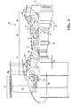
- FIG. 1 schematically illustrates a gas turbine engine 20.
- the gas turbine engine 20 is disclosed herein as a two-spool turbo fan that generally incorporates a fan section 22, a compressor section 24, a combustor section 26 and a turbine section 28.
- the fan section 22 drives air along a bypass flowpath while the compressor section 24 drives air along a core flowpath for compression and communication into the combustor section 26 then expansion through the turbine section 28.
- turbofan in the disclosed non-limiting embodiment, it should be understood that the concepts described herein are not limited to use with turbofans as the teachings may be applied to other types of turbine engines such as a turbojets, turboshafts, and three-spool (plus fan) turbofans wherein an intermediate spool includes an intermediate pressure compressor ("IPC") between a Low Pressure Compressor (“LPC”) and a High Pressure Compressor (“HPC”), and an intermediate pressure turbine (“IPT”) between the high pressure turbine (“HPT”) and the Low pressure Turbine (“LPT”).
- IPC intermediate pressure compressor
- LPC Low Pressure Compressor
- HPC High Pressure Compressor
- IPT intermediate pressure turbine
- the engine 20 generally includes a low spool 30 and a high spool 32 mounted for rotation about an engine central longitudinal axis A relative to an engine static structure 36 via several bearing structures 38.
- the low spool 30 generally includes an inner shaft 40 that interconnects a fan 42, a low pressure compressor (“LPC”) 44 and a low pressure turbine (“LPT”) 46.
- the inner shaft 40 drives the fan 42 directly or through a geared architecture 48 to drive the fan 42 at a lower speed than the low spool 30.
- An exemplary reduction transmission is an epicyclic transmission, namely a planetary or star gear system.
- the high spool 32 includes an outer shaft 50 that interconnects a high pressure compressor (“HPC”) 52 and high pressure turbine (“HPT”) 54.
- a combustor 56 is arranged between the high pressure compressor 52 and the high pressure turbine 54.
- the inner shaft 40 and the outer shaft 50 are concentric and rotate about the engine central longitudinal axis A which is collinear with their longitudinal axes.
- the main engine shafts 40, 50 are supported at a plurality of points by bearing structures 38 within the static structure 36. It should be understood that various bearing structures 38 at various locations may alternatively or additionally be provided.
- the combustor section 26 generally includes a combustor 56 with an outer combustor liner assembly 60, an inner combustor liner assembly 62 and a diffuser case module 64.
- the outer combustor liner assembly 60 and the inner combustor liner assembly 62 are spaced apart such that a combustion chamber 66 is defined therebetween.
- the combustion chamber 66 is generally annular in shape.
- the outer combustor liner assembly 60 is spaced radially inward from an outer diffuser case 64-O of the diffuser case module 64 to define an outer annular plenum 76.
- the inner combustor liner assembly 62 is spaced radially outward from an inner diffuser case 64-I of the diffuser case module 64 to define an inner annular plenum 78. It should be understood that although a particular combustor is illustrated, other combustor types with various combustor liner arrangements will also benefit herefrom. It should be further understood that the disclosed cooling flow paths are but an illustrated embodiment and should not be limited only thereto.
- each combustor liner assembly 60, 62 contain the combustion products for direction toward the turbine section 28.
- Each combustor liner assembly 60, 62 generally includes a respective support shell 68, 70 which supports one or more liner panels 72, 74 mounted to a hot side of the respective support shell 68, 70.
- a dual wall liner assembly is illustrated, a single-wall liner may also benefit herefrom.
- Each of the liner panels 72, 74 may be generally rectilinear and manufactured of, for example, a nickel based super alloy, ceramic or other temperature resistant material and are arranged to form a liner array.
- the liner array includes a multiple of forward liner panels 72A and a multiple of aft liner panels 72B that are circumferentially staggered to line the hot side of the outer shell 68 (also shown in FIG. 3 ).
- a multiple of forward liner panels 74A and a multiple of aft liner panels 74B are circumferentially staggered to line the hot side of the inner shell 70 (also shown in FIG. 3 ).
- the combustor 56 further includes a forward assembly 80 immediately downstream of the compressor section 24 to receive compressed airflow therefrom.
- the forward assembly 80 generally includes an annular hood 82, a bulkhead assembly 84, a multiple of forward fuel nozzles 86 (one shown) and a multiple of swirlers 90 (one shown).
- the multiple of fuel nozzles 86 (one shown) and the multiple of swirlers 90 (one shown) define a fuel injection system 93 for a Rich-Quench-Lean (RQL) combustor that directs the fuel-air mixture into the combustor chamber generally along an axis F.
- the fuel injection system 93 in this embodiment, is the only fuel injection system.
- the bulkhead assembly 84 includes a bulkhead support shell 96 secured to the combustor liner assemblies 60, 62, and a multiple of circumferentially distributed bulkhead liner panels 98 secured to the bulkhead support shell 96.
- the annular hood 82 extends radially between, and is secured to, the forwardmost ends of the combustor liner assemblies 60, 62.
- the annular hood 82 includes a multiple of circumferentially distributed hood ports 94 that accommodate the respective forward fuel nozzles 86 and direct air into the forward end of the combustion chamber 66 through a respective swirler 90.
- Each forward fuel nozzle 86 may be secured to the diffuser case module 64 and project through one of the hood ports 94 and through the respective swirler 90.
- Each of the fuel nozzles 86 is directed through the respective swirler 90 and the bulkhead assembly 84 along a respective axis F.
- the forward assembly 80 introduces primary combustion air into the forward section of the combustion chamber 66 while the remainder enters the outer annular plenum 76 and the inner annular plenum 78.
- the multiple of fuel nozzles 86 and adjacent structure generate a blended fuel-air mixture that supports stable combustion in the combustion chamber 66.
- the outer and inner support shells 68, 70 are mounted to a first row of Nozzle Guide Vanes (NGVs) 54A in the HPT 54 to define a combustor exit 100.
- NGVs 54A are static engine components which direct core airflow combustion gases onto the turbine blades of the first turbine rotor in the turbine section 28 to facilitate the conversion of pressure energy into kinetic energy.
- the combustion gases are also accelerated by the NGVs 54A because of their convergent shape and are typically given a "spin” or a "swirl” in the direction of turbine rotor rotation.
- the turbine rotor blades absorb this energy to drive the turbine rotor at high speed.
- a multiple of cooling impingement holes 104 penetrate through the support shells 68, 70 to allow air from the respective annular plenums 76, 78 to enter cavities 106A, 106B formed in the combustor liner assemblies 60, 62 between the respective support shells 68, 70 and liner panels 72, 74.
- the cooling impingement holes 104 are generally normal to the surface of the liner panels 72, 74.
- the air in the cavities 106A, 106B provides cold side impingement cooling of the liner panels 72, 74 that is generally defined herein as heat removal via internal convection.
- the geometry of the film holes, e.g., diameter, shape, density, surface angle, incidence angle, etc., as well as the location of the holes with respect to the high temperature main flow also contributes to effusion film cooling.
- the liner panels 72, 74 with a combination of impingement holes 104 and film holes 108 may sometimes be referred to as an Impingement Film Floatliner assembly.
- Other liner construction and cooling techniques may be used instead, such as a single-wall liner.
- the cooling film holes 108 allow the air to pass from the cavities 106A, 106B defined in part by a cold side 110 of the liner panels 72, 74 to a hot side 112 of the liner panels 72, 74 and thereby facilitate the formation of a film of cooling air along the hot side 112.
- the cooling film holes 108 are generally more numerous than the impingement holes 104 to promote the development of a film cooling along the hot side 112 to sheath the liner panels 72, 74.
- Film cooling as defined herein is the introduction of a relatively cooler airflow at one or more discrete locations along a surface exposed to a high temperature environment to protect that surface in the immediate region of the airflow injection as well as downstream thereof. It should be appreciated that other combustors using an entirely different methods of combustor-liner cooling, including single-walled liners, backside-cooled liners, non-metallic CMC liners, etc., may alternatively be utilized.
- a multiple of dilution holes 116 may penetrate through both the respective support shells 68, 70 and liner panels 72, 74 along a common axis downstream of the forward assembly 80 to diilute the hot gases by supplying cooling air and/or additional combustion air radially into the combustor. That is, the multiple of dilution holes 116 provide a direct path for airflow from the annular plenums 76, 78 into the combustion chamber 66. In other example combustors the fuel/air mixture in the combustor does not require dilution, and such a combustor may not require dilution holes.
- a main fuel injection system 120 communicates with the combustion chamber 66 downstream of an axial pilot fuel injection system 92 generally transverse to axis F of an Axially Controlled Stoichiometry (ACS) Combustor.
- ACS Axially Controlled Stoichiometry
- the main fuel injection system 120 introduces a portion of the fuel required for desired combustion performance, e.g., emissions, operability, durability.
- the main fuel injection system 120 is positioned downstream of the axial pilot fuel injection system 92 and upstream of the multiple of dilution holes 116 if so equipped.
- the main fuel injection system 120 generally includes an outer fuel injection manifold 122 (illustrated schematically) and/or an inner fuel injection manifold 124 (illustrated schematically) with a respective multiple of outer fuel nozzles 126 and a multiple of inner fuel nozzles 128.
- the outer fuel injection manifold 122 and/or inner fuel injection manifold 124 may be mounted to the diffuser case module 64 and/or to the shell 68, 70, however, various mount arrangements may alternatively or additionally provided.
- Each of the multiple of outer and inner fuel nozzles 126, 128 are located within a respective mixer 130, 132 to mix the supply of fuel into the pressurized air within the diffuser case module 64 as it passes through the mixer to enter the combustion chamber 66.
- a “mixer” as compared to a “swirler” may generate, for example, zero swirl, a counterrotating swirl, a specific swirl which provides a resultant swirl or a residual net swirl which may be further directed at an angle. It should be appreciated that various combinations thereof may alternatively be utilized.
- the main fuel injection system 120 may include only the radially outer fuel injection manifold 122 with the multiple of outer fuel nozzles 126; only the radially inner fuel injection manifold 124 with the multiple of inner fuel nozzles 128; or both (shown). Alternatively, the main fuel injection system 120 may only be located in the bulkhead assembly 84. It should be appreciated that the main fuel injection system 120 may include single sets of outer fuel nozzles 126 and inner fuel nozzles 128 (shown) or multiple axially distributed sets of, for example, relatively smaller fuel nozzles.
- each of the multiple of outer and inner fuel nozzles 126, 128 are respectively located within the associated mixer 130, 132 to each form an annular main mixer 200 (one shown).
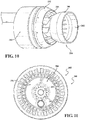
- Each annular main mixer 200 generally includes a swirler 202 ( FIGs. 7 and 8 ) and a swirler hub 204 ( FIGs. 9 and 10 ) along a common axis X ( FIG. 11 and 12 ).
- the swirler hub 204 generally includes a fuel manifold 210, and an inner swirler 212 with a multiple of inner vanes 214 that supports a centerbody 216.
- the inner vanes 214 may or may not have an aerodynamic aspect and thus may be more particularly described as struts or attachment points.
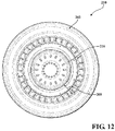
- the outer surface 206 of the centerbody 216 forms an inner diameter of an annular mixer passage 208 while an inner diameter 209 of the swirler forms an outer diameter of the annular mixer passage 208.
- a ratio of the gap height of the annular mixer passage 208 to the swirler hub 204 radius ranges from 0.2 to 1.2.
- the apex (stagnation-point) and the attachment points for the swirler hub 204 are in a pure air stream passing through the center of hub 204, which because of the absence of fuel, precludes the possibility of flameholding and overheating of the swirler hub 204.
- the swirler 202 includes an outer swirler 218 with a multiple of outer vanes 220, and a center swirler 222 with a multiple of center vanes 224.
- the outer swirler 218 defines a diameter generally larger than the annular mixer passage 208 diameter. That is, the inner diameter 209 decreases downstream of the outer swirler 218.
- the multiple of outer vanes 220 are formed to counter-rotate with the multiple of center vanes 224 and to co-rotate with respect to the inner vanes 214 if they impart swirl.
- the airflow from the inner swirler 212 enhances mixing by providing a shear layer to increase fuel jet penetration as well as minimize or eliminate the low velocity region associated with airflow swirl and fuel jets.
- air flow from the inner swirler 212 takes 20% to 45% of total main mixer air flow
- the center swirler takes 30% to 40% of total main mixer air flow
- outer swirler takes 30% to 50% of total main mixer air flow
- the cross sectional area from where the inner air meets the air flow from center and outer to the mixer exit generally remain constants or slightly converging.
- the multiple of inner vanes 214 interconnect the fuel manifold 210 and the centerbody 216 ( FIG 10 ) to define an unfueled annular air passage 217.
- the unfueled annular air passage 217 avoids burning (no overheating) upstream of the multiple of inner vanes 214 and/or upstream of the cooling features of the centerbody 216.
- the fuel manifold 210 includes a downstream section 230 with a multiple of fuel jets 232 that extend through an outer surface 234 of the fuel manifold 210.
- the multiple of fuel jets 232 may form an angle with respect to the center axis X of the mixer or may be otherwise oriented and/or arranged. The angle from where the inner air meets the air flow from center and outer to the mixer exit ranges from 0 to 30 degrees.
- the multiple of fuel jets 232 thereby inject fuel generally outward into the airflow downstream of the outer swirler 218 and the center swirler 222.
- the centerbody 216 may be a conical, frustro-conical, cylindrical, or other shape.
- the centerbody 216 may include a first multiple of effusion/film cooling passages 240 and a second multiple of effusion/film cooling passages 242 ( FIG. 6 ).
- the first multiple of effusion/film cooling passages 240 may include inlets 241 arranged in a circular distribution in an upstream wall 250 ( FIG. 6 ) of the centerbody 216 to define circular exits 244.
- the second multiple of effusion/film cooling passages 242 may also include inlets 243 ( FIG. 6 ) arranged in a circular distribution in the upstream wall 250 of the centerbody 216 and extend through a sidewall 246 to form non-circular exits 248.
- the second multiple of effusion/film cooling passages 242 extend through the sidewall 246 to exit obliquely through an interior of the centerbody 216. It should be appreciated that other hole shapes and locations could also be employed other than the illustrated round holes in circular patterns.
- TBC thermal barrier coatings
- the TBC is typically a ceramic material deposited on a bond coat to form what may be termed a TBC system.
- Bond coat materials widely used in TBC systems include oxidation-resistant overlay coatings such as MCrA1X (where M is iron, cobalt and/or nickel, and X is yttrium or another rare earth element), and diffusion coatings such as diffusion aluminides that contain aluminum intermetallics.
- Ceramic materials and particularly binary yttria-stabilized zirconia (YSZ) are widely used as TBC materials because of their high temperature capability, low thermal conductivity, and relative ease of deposition such as by air plasma spraying (APS), flame spraying such as hyper-velocity oxy-fuel (HVOF), physical vapor deposition (PVD) and other techniques.
- APS air plasma spraying
- HVOF hyper-velocity oxy-fuel
- PVD physical vapor deposition
- the multiple of impingement cooling passages 240 which may be the first multiple of effusion/film cooling passages, provide backside impingement cooling in the center region and backside convective cooling away from the center region.
- typical impingement and convective cooling velocity ranges from 50 to 150 m/sec for cooling, or to minimize flame propagation upstream thereof.
- the second multiple of effusion/film cooling passages 242 provide additional convective cooling to generate film cooling along the inner surface 260.
- the flow from the second multiple of effusion/film cooling passages 242 may have a tangential angle to the inner surface to provide swirling cooling flow.
- total cooling flow utilizes less than 1% of combustor chamber cooling flow. Fuel injection within the mixer lowers the temperature of the backside cooling flow, providing further cooling benefit.
- the integral annular main mixer 200 provides for stable and robust anchoring/flameholding of the main zone reacting jet, which facilitates good combustion efficiency, improved dynamic stability, prevention of intermittent flame lift-off, and potential mitigation of combustion dynamics. Further, the integral annular main mixer 200 enhances flame stability by contact with burned gases in these regions.
- Fuel shifting or fuel biasing can be used to create a richer F/A mixture at a specific location where the flame anchoring is desired.
- Fuel shifting and fuel biasing for a liquid-fueled aero engine axially-staged lean-lean combustor configuration may be provided by radial fuel re-distribution within the swirler, and/or non-uniform circumferential distribution within or with respect to the swirler. Fuel shifting may also be applied between one swirler or mixer and another, or between sets of swirlers or mixers.
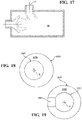
- an integral annular main mixer 200A in accord with another disclosed non-limiting embodiment is of a lobed shape 300. That is, the outer surface 206A of the center section 216A forms a non-circular inner surface of the annular mixer passage 208A while an inner diameter 209A of the swirler 202A forms an outer surface of the annular mixer passage 208A.
- annular main mixer exit passage 208B in accord with another disclosed non-limiting embodiment is of an elliptical shape 400.
- annular main mixer exit passage 208C in accords with another disclosed non-limiting embodiment is of a contoured shape 500.
- Various other shapes may alternatively or additionally be provided. That is, the annular mixer passage 208 need not be circular or coaxial with the axis X to address addresses known ACS complications such as main mixer scalability; main mixer sooting potential; fuel nozzle count reduction; and cruise efficiency.
- an annular main mixer exit passage 208D in accord with another disclosed non-limiting embodiment includes a flat leading edge 600 on the inner diameter 209D of the swirler 202D. That is, the flat leading edge 600 on the inner diameter 209D of the swirler 202D is on the windward side with respect to the flow through the combustion chamber 66 ( FIG. 17 ).
- annular main mixer exit passage 208E offsets the centerbody 216E within the swirler 202E to form a non-axis symmetric annular mixer passage 208E.
- the centerbody 216E is offset within the swirler 202E toward the windward side.
- an annular main mixer exit passage 208F in accord with another disclosed non-limiting embodiment includes an aperture 800 through the swirler 202F. That is, the aperture 800 on the inner diameter 209F of the swirler 202F is on the windward side with respect to the flow through the combustion chamber 66
- the annular main mixer 200 includes annular main mixers having concentric counterrotating axial and/or radial swirler vane passages, an annular fuel plenum from which fuel is injected (preferably between concentric vane passages), and a swirler hub that can take various shapes but which together with the outer wall defines the annular mixer exit. Since the annular main mixer 200 is the main-stage in an ACS combustor, a pilot is not required, and is not included in the mixer, and bulk swirl is minimal and not required, thus the design and operation is itself different from mixers used in non-ACS combustors.
- the annular main mixer 200 provides for stable and robust anchoring/flameholding of the main zone reacting jet, which facilitates mitigation of combustion dynamics, improved dynamic stability, and prevention of intermittent flame lift-off. Further, the annular main mixer 200 enhances flame stability by contact with burned gases in these regions. Fuel shifting or fuel biasing can be used to create a richer F/A mixture at a specific location where the flame anchoring is desired. Fuel shifting and fuel biasing for a liquid-fueled aero engine axially-staged lean-lean combustor configuration may be provided by radial fuel re-distribution within the swirler, and/or non-uniform circumferential distribution within or with respect to the swirler.
Landscapes
- Engineering & Computer Science (AREA)
- Chemical & Material Sciences (AREA)
- Combustion & Propulsion (AREA)
- Mechanical Engineering (AREA)
- General Engineering & Computer Science (AREA)
- Turbine Rotor Nozzle Sealing (AREA)
- Pre-Mixing And Non-Premixing Gas Burner (AREA)
Priority Applications (2)
| Application Number | Priority Date | Filing Date | Title |
|---|---|---|---|
| EP22168013.5A EP4047274B1 (de) | 2016-12-07 | 2017-10-06 | Hauptmischer in einer axialen gestuften brennkammer für einen gasturbinenmotor |
| EP24195427.0A EP4438951A3 (de) | 2016-12-07 | 2017-10-06 | Hauptmischer in einer axial gestuften brennkammer für einen gasturbinenmotor |
Applications Claiming Priority (1)
| Application Number | Priority Date | Filing Date | Title |
|---|---|---|---|
| US15/371,653 US11149952B2 (en) | 2016-12-07 | 2016-12-07 | Main mixer in an axial staged combustor for a gas turbine engine |
Related Child Applications (2)
| Application Number | Title | Priority Date | Filing Date |
|---|---|---|---|
| EP22168013.5A Division EP4047274B1 (de) | 2016-12-07 | 2017-10-06 | Hauptmischer in einer axialen gestuften brennkammer für einen gasturbinenmotor |
| EP24195427.0A Division EP4438951A3 (de) | 2016-12-07 | 2017-10-06 | Hauptmischer in einer axial gestuften brennkammer für einen gasturbinenmotor |
Publications (3)
| Publication Number | Publication Date |
|---|---|
| EP3333485A2 true EP3333485A2 (de) | 2018-06-13 |
| EP3333485A3 EP3333485A3 (de) | 2018-11-28 |
| EP3333485B1 EP3333485B1 (de) | 2022-04-13 |
Family
ID=60037514
Family Applications (3)
| Application Number | Title | Priority Date | Filing Date |
|---|---|---|---|
| EP22168013.5A Active EP4047274B1 (de) | 2016-12-07 | 2017-10-06 | Hauptmischer in einer axialen gestuften brennkammer für einen gasturbinenmotor |
| EP24195427.0A Pending EP4438951A3 (de) | 2016-12-07 | 2017-10-06 | Hauptmischer in einer axial gestuften brennkammer für einen gasturbinenmotor |
| EP17195301.1A Active EP3333485B1 (de) | 2016-12-07 | 2017-10-06 | Hauptmischer in einer axialen gestuften brennkammer für einen gasturbinenmotor |
Family Applications Before (2)
| Application Number | Title | Priority Date | Filing Date |
|---|---|---|---|
| EP22168013.5A Active EP4047274B1 (de) | 2016-12-07 | 2017-10-06 | Hauptmischer in einer axialen gestuften brennkammer für einen gasturbinenmotor |
| EP24195427.0A Pending EP4438951A3 (de) | 2016-12-07 | 2017-10-06 | Hauptmischer in einer axial gestuften brennkammer für einen gasturbinenmotor |
Country Status (2)
| Country | Link |
|---|---|
| US (3) | US11149952B2 (de) |
| EP (3) | EP4047274B1 (de) |
Families Citing this family (9)
| Publication number | Priority date | Publication date | Assignee | Title |
|---|---|---|---|---|
| US11149952B2 (en) * | 2016-12-07 | 2021-10-19 | Raytheon Technologies Corporation | Main mixer in an axial staged combustor for a gas turbine engine |
| US11378277B2 (en) * | 2018-04-06 | 2022-07-05 | General Electric Company | Gas turbine engine and combustor having air inlets and pilot burner |
| US11441778B2 (en) * | 2019-12-20 | 2022-09-13 | Raytheon Technologies Corporation | Article with cooling holes and method of forming the same |
| US11713881B2 (en) | 2020-01-08 | 2023-08-01 | General Electric Company | Premixer for a combustor |
| US11761632B2 (en) * | 2021-08-05 | 2023-09-19 | General Electric Company | Combustor swirler with vanes incorporating open area |
| US11619172B1 (en) | 2022-03-01 | 2023-04-04 | General Electric Company | Detonation combustion systems |
| GB202211656D0 (en) * | 2022-08-10 | 2022-09-21 | Rolls Royce Plc | A fuel injector |
| US12111056B2 (en) * | 2023-02-02 | 2024-10-08 | Pratt & Whitney Canada Corp. | Combustor with central fuel injection and downstream air mixing |
| US12130016B1 (en) | 2023-05-31 | 2024-10-29 | General Electric Company | Turbine engine including a combustor |
Family Cites Families (84)
| Publication number | Priority date | Publication date | Assignee | Title |
|---|---|---|---|---|
| US3980233A (en) * | 1974-10-07 | 1976-09-14 | Parker-Hannifin Corporation | Air-atomizing fuel nozzle |
| US5020329A (en) * | 1984-12-20 | 1991-06-04 | General Electric Company | Fuel delivery system |
| CA1306873C (en) * | 1987-04-27 | 1992-09-01 | Jack R. Taylor | Low coke fuel injector for a gas turbine engine |
| US5207064A (en) * | 1990-11-21 | 1993-05-04 | General Electric Company | Staged, mixed combustor assembly having low emissions |
| FR2698157B1 (fr) * | 1992-11-18 | 1994-12-16 | Snecma | Système d'injection aérodynamique de chambre de combustion. |
| US5392720A (en) * | 1994-06-07 | 1995-02-28 | Riley Stoker Corporation | Flame retaining nozzle tip |
| US5826423A (en) | 1996-11-13 | 1998-10-27 | Solar Turbines Incorporated | Dual fuel injection method and apparatus with multiple air blast liquid fuel atomizers |
| US6038861A (en) * | 1998-06-10 | 2000-03-21 | Siemens Westinghouse Power Corporation | Main stage fuel mixer with premixing transition for dry low Nox (DLN) combustors |
| US6119459A (en) * | 1998-08-18 | 2000-09-19 | Alliedsignal Inc. | Elliptical axial combustor swirler |
| GB9911871D0 (en) | 1999-05-22 | 1999-07-21 | Rolls Royce Plc | A gas turbine engine and a method of controlling a gas turbine engine |
| US6253538B1 (en) | 1999-09-27 | 2001-07-03 | Pratt & Whitney Canada Corp. | Variable premix-lean burn combustor |
| US6536216B2 (en) | 2000-12-08 | 2003-03-25 | General Electric Company | Apparatus for injecting fuel into gas turbine engines |
| US6625971B2 (en) | 2001-09-14 | 2003-09-30 | United Technologies Corporation | Fuel nozzle producing skewed spray pattern |
| US7185497B2 (en) | 2004-05-04 | 2007-03-06 | Honeywell International, Inc. | Rich quick mix combustion system |
| US7140189B2 (en) | 2004-08-24 | 2006-11-28 | Pratt & Whitney Canada Corp. | Gas turbine floating collar |
| US7134286B2 (en) | 2004-08-24 | 2006-11-14 | Pratt & Whitney Canada Corp. | Gas turbine floating collar arrangement |
| US7308794B2 (en) | 2004-08-27 | 2007-12-18 | Pratt & Whitney Canada Corp. | Combustor and method of improving manufacturing accuracy thereof |
| US7269958B2 (en) | 2004-09-10 | 2007-09-18 | Pratt & Whitney Canada Corp. | Combustor exit duct |
| JP2006300448A (ja) * | 2005-04-22 | 2006-11-02 | Mitsubishi Heavy Ind Ltd | ガスタービンの燃焼器 |
| US7779636B2 (en) * | 2005-05-04 | 2010-08-24 | Delavan Inc | Lean direct injection atomizer for gas turbine engines |
| US7624576B2 (en) | 2005-07-18 | 2009-12-01 | Pratt & Whitney Canada Corporation | Low smoke and emissions fuel nozzle |
| US7565803B2 (en) | 2005-07-25 | 2009-07-28 | General Electric Company | Swirler arrangement for mixer assembly of a gas turbine engine combustor having shaped passages |
| US7559202B2 (en) | 2005-11-15 | 2009-07-14 | Pratt & Whitney Canada Corp. | Reduced thermal stress fuel nozzle assembly |
| JP2007162998A (ja) * | 2005-12-13 | 2007-06-28 | Kawasaki Heavy Ind Ltd | ガスタービンエンジンの燃料噴霧装置 |
| US7721436B2 (en) | 2005-12-20 | 2010-05-25 | Pratt & Whitney Canada Corp. | Method of manufacturing a metal injection moulded combustor swirler |
| US7762073B2 (en) | 2006-03-01 | 2010-07-27 | General Electric Company | Pilot mixer for mixer assembly of a gas turbine engine combustor having a primary fuel injector and a plurality of secondary fuel injection ports |
| US7716931B2 (en) | 2006-03-01 | 2010-05-18 | General Electric Company | Method and apparatus for assembling gas turbine engine |
| US7950233B2 (en) | 2006-03-31 | 2011-05-31 | Pratt & Whitney Canada Corp. | Combustor |
| EP1847778A1 (de) | 2006-04-21 | 2007-10-24 | Siemens Aktiengesellschaft | Vormischverbrennungsanlage für Gasturbine und Verfahren zum Betrieb |
| US7631500B2 (en) * | 2006-09-29 | 2009-12-15 | General Electric Company | Methods and apparatus to facilitate decreasing combustor acoustics |
| GB0625016D0 (en) * | 2006-12-15 | 2007-01-24 | Rolls Royce Plc | Fuel injector |
| FR2911667B1 (fr) | 2007-01-23 | 2009-10-02 | Snecma Sa | Systeme d'injection de carburant a double injecteur. |
| US8171736B2 (en) | 2007-01-30 | 2012-05-08 | Pratt & Whitney Canada Corp. | Combustor with chamfered dome |
| EP1975506A1 (de) * | 2007-03-30 | 2008-10-01 | Siemens Aktiengesellschaft | Vorverbrennungskammer |
| US8146365B2 (en) | 2007-06-14 | 2012-04-03 | Pratt & Whitney Canada Corp. | Fuel nozzle providing shaped fuel spray |
| DE102007043626A1 (de) * | 2007-09-13 | 2009-03-19 | Rolls-Royce Deutschland Ltd & Co Kg | Gasturbinenmagerbrenner mit Kraftstoffdüse mit kontrollierter Kraftstoffinhomogenität |
| US8387398B2 (en) | 2007-09-14 | 2013-03-05 | Siemens Energy, Inc. | Apparatus and method for controlling the secondary injection of fuel |
| US7658339B2 (en) | 2007-12-20 | 2010-02-09 | Pratt & Whitney Canada Corp. | Modular fuel nozzle air swirler |
| US7926744B2 (en) * | 2008-02-21 | 2011-04-19 | Delavan Inc | Radially outward flowing air-blast fuel injector for gas turbine engine |
| US8459017B2 (en) | 2008-04-09 | 2013-06-11 | Woodward, Inc. | Low pressure drop mixer for radial mixing of internal combustion engine exhaust flows, combustor incorporating same, and methods of mixing |
| US9188341B2 (en) * | 2008-04-11 | 2015-11-17 | General Electric Company | Fuel nozzle |
| US8061142B2 (en) * | 2008-04-11 | 2011-11-22 | General Electric Company | Mixer for a combustor |
| JP5472863B2 (ja) | 2009-06-03 | 2014-04-16 | 独立行政法人 宇宙航空研究開発機構 | ステージング型燃料ノズル |
| US8991192B2 (en) | 2009-09-24 | 2015-03-31 | Siemens Energy, Inc. | Fuel nozzle assembly for use as structural support for a duct structure in a combustor of a gas turbine engine |
| EP2362148A1 (de) * | 2010-02-23 | 2011-08-31 | Siemens Aktiengesellschaft | Brennstoffinjektor und Drallvorrichtung mit lappenartigem Mischer |
| US8752386B2 (en) | 2010-05-25 | 2014-06-17 | Siemens Energy, Inc. | Air/fuel supply system for use in a gas turbine engine |
| US8850819B2 (en) * | 2010-06-25 | 2014-10-07 | United Technologies Corporation | Swirler, fuel and air assembly and combustor |
| US9435537B2 (en) * | 2010-11-30 | 2016-09-06 | General Electric Company | System and method for premixer wake and vortex filling for enhanced flame-holding resistance |
| US8387391B2 (en) * | 2010-12-17 | 2013-03-05 | General Electric Company | Aerodynamically enhanced fuel nozzle |
| US20120151928A1 (en) * | 2010-12-17 | 2012-06-21 | Nayan Vinodbhai Patel | Cooling flowpath dirt deflector in fuel nozzle |
| US8726668B2 (en) * | 2010-12-17 | 2014-05-20 | General Electric Company | Fuel atomization dual orifice fuel nozzle |
| US8850779B2 (en) | 2011-01-25 | 2014-10-07 | International Ice Bagging Systems, Llc | Ice bagging system |
| US8312724B2 (en) | 2011-01-26 | 2012-11-20 | United Technologies Corporation | Mixer assembly for a gas turbine engine having a pilot mixer with a corner flame stabilizing recirculation zone |
| US8973368B2 (en) * | 2011-01-26 | 2015-03-10 | United Technologies Corporation | Mixer assembly for a gas turbine engine |
| US8925325B2 (en) * | 2011-03-18 | 2015-01-06 | Delavan Inc. | Recirculating product injection nozzle |
| JP5772245B2 (ja) * | 2011-06-03 | 2015-09-02 | 川崎重工業株式会社 | 燃料噴射装置 |
| DE112011105655B4 (de) | 2011-09-22 | 2023-05-25 | General Electric Company | Brenner und Verfahren zur Brennstoffzufuhr zu einem Brenner |
| US9188340B2 (en) | 2011-11-18 | 2015-11-17 | General Electric Company | Gas turbine combustor endcover with adjustable flow restrictor and related method |
| DE102012002465A1 (de) * | 2012-02-08 | 2013-08-08 | Rolls-Royce Deutschland Ltd & Co Kg | Gasturbinenbrennkammer mit unsymmetrischen Kraftstoffdüsen |
| US9097424B2 (en) | 2012-03-12 | 2015-08-04 | General Electric Company | System for supplying a fuel and working fluid mixture to a combustor |
| JP5988261B2 (ja) * | 2012-06-07 | 2016-09-07 | 川崎重工業株式会社 | 燃料噴射装置 |
| US9441836B2 (en) * | 2012-07-10 | 2016-09-13 | United Technologies Corporation | Fuel-air pre-mixer with prefilmer |
| US9115896B2 (en) * | 2012-07-31 | 2015-08-25 | General Electric Company | Fuel-air mixer for use with a combustor assembly |
| US9488108B2 (en) * | 2012-10-17 | 2016-11-08 | Delavan Inc. | Radial vane inner air swirlers |
| GB201222304D0 (en) * | 2012-12-12 | 2013-01-23 | Rolls Royce Plc | A fuel injector and a gas turbine engine combustion chamber |
| US9404656B2 (en) * | 2012-12-17 | 2016-08-02 | United Technologies Corporation | Oblong swirler assembly for combustors |
| US9376985B2 (en) * | 2012-12-17 | 2016-06-28 | United Technologies Corporation | Ovate swirler assembly for combustors |
| US9920693B2 (en) | 2013-03-14 | 2018-03-20 | United Technologies Corporation | Hollow-wall heat shield for fuel injector component |
| WO2015040228A1 (de) | 2013-09-23 | 2015-03-26 | Siemens Aktiengesellschaft | Brenner für eine gasturbine und verfahren zur reduzierung von thermoakustischen schwingungen in einer gasturbine |
| US10907833B2 (en) * | 2014-01-24 | 2021-02-02 | Raytheon Technologies Corporation | Axial staged combustor with restricted main fuel injector |
| US10054312B2 (en) | 2015-02-25 | 2018-08-21 | United Technologies Corporation | Pilot mixer cooling hole arrangement for fuel nozzle of a gas turbine engine |
| GB201516977D0 (en) * | 2015-09-25 | 2015-11-11 | Rolls Royce Plc | A Fuel Injector For A Gas Turbine Engine Combustion Chamber |
| US10132500B2 (en) * | 2015-10-16 | 2018-11-20 | Delavan Inc. | Airblast injectors |
| GB2543803B (en) * | 2015-10-29 | 2019-10-30 | Rolls Royce Plc | A combustion chamber assembly |
| US10502425B2 (en) * | 2016-06-03 | 2019-12-10 | General Electric Company | Contoured shroud swirling pre-mix fuel injector assembly |
| US11149952B2 (en) * | 2016-12-07 | 2021-10-19 | Raytheon Technologies Corporation | Main mixer in an axial staged combustor for a gas turbine engine |
| EP3704386B1 (de) * | 2017-11-02 | 2024-01-17 | MTU Aero Engines AG | Generativ gefertigter zwischenkanal zur anordnung zwischen einem niederdruckverdichter und einem hochdruckverdichter, sowie entsprechendes fertigungsverfahren |
| US10808934B2 (en) * | 2018-01-09 | 2020-10-20 | General Electric Company | Jet swirl air blast fuel injector for gas turbine engine |
| WO2019150336A1 (en) * | 2018-02-04 | 2019-08-08 | Bower Newton | Rotary engine |
| US11143406B2 (en) * | 2018-04-10 | 2021-10-12 | Delavan Inc. | Fuel injectors having air sealing structures |
| US10935245B2 (en) * | 2018-11-20 | 2021-03-02 | General Electric Company | Annular concentric fuel nozzle assembly with annular depression and radial inlet ports |
| GB201904677D0 (en) * | 2019-04-03 | 2019-05-15 | Rolls Royce Plc | Oil pipe assembly |
| EP4644774A3 (de) * | 2019-07-19 | 2025-12-24 | Milwaukee Electric Tool Corporation | Standleuchte |
| EP4021631B1 (de) * | 2019-08-27 | 2025-06-25 | SABIC Global Technologies, B.V. | Massentransferdrallkörper mit verteilerelement |
-
2016
- 2016-12-07 US US15/371,653 patent/US11149952B2/en active Active
-
2017
- 2017-10-06 EP EP22168013.5A patent/EP4047274B1/de active Active
- 2017-10-06 EP EP24195427.0A patent/EP4438951A3/de active Pending
- 2017-10-06 EP EP17195301.1A patent/EP3333485B1/de active Active
-
2021
- 2021-07-08 US US17/370,154 patent/US11815268B2/en active Active
-
2023
- 2023-10-06 US US18/377,406 patent/US12560326B2/en active Active
Non-Patent Citations (1)
| Title |
|---|
| None |
Also Published As
| Publication number | Publication date |
|---|---|
| EP4438951A3 (de) | 2025-09-03 |
| EP4047274A2 (de) | 2022-08-24 |
| US11815268B2 (en) | 2023-11-14 |
| US12560326B2 (en) | 2026-02-24 |
| EP4438951A2 (de) | 2024-10-02 |
| US20180156464A1 (en) | 2018-06-07 |
| EP3333485B1 (de) | 2022-04-13 |
| US11149952B2 (en) | 2021-10-19 |
| EP4047274B1 (de) | 2024-08-21 |
| US20210372622A1 (en) | 2021-12-02 |
| US20240068665A1 (en) | 2024-02-29 |
| EP4047274A3 (de) | 2023-04-19 |
| EP3333485A3 (de) | 2018-11-28 |
Similar Documents
| Publication | Publication Date | Title |
|---|---|---|
| US12560326B2 (en) | Main mixer in an axial staged combustor for a gas turbine engine | |
| EP3301361B1 (de) | Pilot-/haupttreibstoffwechsel in einer axialstufenbrennkammer für einen gasturbinenmotor | |
| EP3008391B1 (de) | Brennkammer mit axialer stufung für einen gasturbinenmotor | |
| EP3301372B1 (de) | Umlaufende kraftstoffverlagerung und -beaufschlagung in einer axial gestuften brennkammer für einen gasturbinenmotor | |
| US11365884B2 (en) | Radial fuel shifting and biasing in an axial staged combustor for a gas turbine engine | |
| US11156359B2 (en) | Combustor liner panel end rail with diffused interface passage for a gas turbine engine combustor | |
| EP3333486B1 (de) | Hauptmischer für eine gasturbinenmotorbrennkammer | |
| EP3033574B1 (de) | Schottanordnung für gasturbinenbrennkammer und verfahren zur kühlung der schottanordnung | |
| EP2977680B1 (de) | Verdünnungslochanordnung | |
| US10739001B2 (en) | Combustor liner panel shell interface for a gas turbine engine combustor | |
| US20180112597A1 (en) | Combustor seal for a gas turbine engine combustor | |
| EP3315862B1 (de) | Gegossene brennkammerauskleidungsplatte mit radiuskante für gasturbinenbrennkammer |
Legal Events
| Date | Code | Title | Description |
|---|---|---|---|
| PUAI | Public reference made under article 153(3) epc to a published international application that has entered the european phase |
Free format text: ORIGINAL CODE: 0009012 |
|
| STAA | Information on the status of an ep patent application or granted ep patent |
Free format text: STATUS: THE APPLICATION HAS BEEN PUBLISHED |
|
| AK | Designated contracting states |
Kind code of ref document: A2 Designated state(s): AL AT BE BG CH CY CZ DE DK EE ES FI FR GB GR HR HU IE IS IT LI LT LU LV MC MK MT NL NO PL PT RO RS SE SI SK SM TR |
|
| AX | Request for extension of the european patent |
Extension state: BA ME |
|
| RIC1 | Information provided on ipc code assigned before grant |
Ipc: F23R 3/14 20060101ALI20180628BHEP Ipc: F23R 3/28 20060101AFI20180628BHEP |
|
| PUAL | Search report despatched |
Free format text: ORIGINAL CODE: 0009013 |
|
| AK | Designated contracting states |
Kind code of ref document: A3 Designated state(s): AL AT BE BG CH CY CZ DE DK EE ES FI FR GB GR HR HU IE IS IT LI LT LU LV MC MK MT NL NO PL PT RO RS SE SI SK SM TR |
|
| AX | Request for extension of the european patent |
Extension state: BA ME |
|
| RIC1 | Information provided on ipc code assigned before grant |
Ipc: F23R 3/28 20060101AFI20181023BHEP Ipc: F23R 3/14 20060101ALI20181023BHEP |
|
| STAA | Information on the status of an ep patent application or granted ep patent |
Free format text: STATUS: REQUEST FOR EXAMINATION WAS MADE |
|
| 17P | Request for examination filed |
Effective date: 20190528 |
|
| RBV | Designated contracting states (corrected) |
Designated state(s): AL AT BE BG CH CY CZ DE DK EE ES FI FR GB GR HR HU IE IS IT LI LT LU LV MC MK MT NL NO PL PT RO RS SE SI SK SM TR |
|
| STAA | Information on the status of an ep patent application or granted ep patent |
Free format text: STATUS: EXAMINATION IS IN PROGRESS |
|
| 17Q | First examination report despatched |
Effective date: 20201116 |
|
| RAP1 | Party data changed (applicant data changed or rights of an application transferred) |
Owner name: RAYTHEON TECHNOLOGIES CORPORATION |
|
| GRAP | Despatch of communication of intention to grant a patent |
Free format text: ORIGINAL CODE: EPIDOSNIGR1 |
|
| STAA | Information on the status of an ep patent application or granted ep patent |
Free format text: STATUS: GRANT OF PATENT IS INTENDED |
|
| INTG | Intention to grant announced |
Effective date: 20211025 |
|
| GRAS | Grant fee paid |
Free format text: ORIGINAL CODE: EPIDOSNIGR3 |
|
| GRAA | (expected) grant |
Free format text: ORIGINAL CODE: 0009210 |
|
| STAA | Information on the status of an ep patent application or granted ep patent |
Free format text: STATUS: THE PATENT HAS BEEN GRANTED |
|
| AK | Designated contracting states |
Kind code of ref document: B1 Designated state(s): AL AT BE BG CH CY CZ DE DK EE ES FI FR GB GR HR HU IE IS IT LI LT LU LV MC MK MT NL NO PL PT RO RS SE SI SK SM TR |
|
| REG | Reference to a national code |
Ref country code: GB Ref legal event code: FG4D |
|
| REG | Reference to a national code |
Ref country code: CH Ref legal event code: EP |
|
| REG | Reference to a national code |
Ref country code: DE Ref legal event code: R096 Ref document number: 602017055835 Country of ref document: DE |
|
| REG | Reference to a national code |
Ref country code: IE Ref legal event code: FG4D |
|
| REG | Reference to a national code |
Ref country code: AT Ref legal event code: REF Ref document number: 1483673 Country of ref document: AT Kind code of ref document: T Effective date: 20220515 |
|
| REG | Reference to a national code |
Ref country code: LT Ref legal event code: MG9D |
|
| REG | Reference to a national code |
Ref country code: NL Ref legal event code: MP Effective date: 20220413 |
|
| REG | Reference to a national code |
Ref country code: AT Ref legal event code: MK05 Ref document number: 1483673 Country of ref document: AT Kind code of ref document: T Effective date: 20220413 |
|
| PG25 | Lapsed in a contracting state [announced via postgrant information from national office to epo] |
Ref country code: NL Free format text: LAPSE BECAUSE OF FAILURE TO SUBMIT A TRANSLATION OF THE DESCRIPTION OR TO PAY THE FEE WITHIN THE PRESCRIBED TIME-LIMIT Effective date: 20220413 |
|
| PG25 | Lapsed in a contracting state [announced via postgrant information from national office to epo] |
Ref country code: SE Free format text: LAPSE BECAUSE OF FAILURE TO SUBMIT A TRANSLATION OF THE DESCRIPTION OR TO PAY THE FEE WITHIN THE PRESCRIBED TIME-LIMIT Effective date: 20220413 Ref country code: PT Free format text: LAPSE BECAUSE OF FAILURE TO SUBMIT A TRANSLATION OF THE DESCRIPTION OR TO PAY THE FEE WITHIN THE PRESCRIBED TIME-LIMIT Effective date: 20220816 Ref country code: NO Free format text: LAPSE BECAUSE OF FAILURE TO SUBMIT A TRANSLATION OF THE DESCRIPTION OR TO PAY THE FEE WITHIN THE PRESCRIBED TIME-LIMIT Effective date: 20220713 Ref country code: LT Free format text: LAPSE BECAUSE OF FAILURE TO SUBMIT A TRANSLATION OF THE DESCRIPTION OR TO PAY THE FEE WITHIN THE PRESCRIBED TIME-LIMIT Effective date: 20220413 Ref country code: HR Free format text: LAPSE BECAUSE OF FAILURE TO SUBMIT A TRANSLATION OF THE DESCRIPTION OR TO PAY THE FEE WITHIN THE PRESCRIBED TIME-LIMIT Effective date: 20220413 Ref country code: GR Free format text: LAPSE BECAUSE OF FAILURE TO SUBMIT A TRANSLATION OF THE DESCRIPTION OR TO PAY THE FEE WITHIN THE PRESCRIBED TIME-LIMIT Effective date: 20220714 Ref country code: FI Free format text: LAPSE BECAUSE OF FAILURE TO SUBMIT A TRANSLATION OF THE DESCRIPTION OR TO PAY THE FEE WITHIN THE PRESCRIBED TIME-LIMIT Effective date: 20220413 Ref country code: ES Free format text: LAPSE BECAUSE OF FAILURE TO SUBMIT A TRANSLATION OF THE DESCRIPTION OR TO PAY THE FEE WITHIN THE PRESCRIBED TIME-LIMIT Effective date: 20220413 Ref country code: BG Free format text: LAPSE BECAUSE OF FAILURE TO SUBMIT A TRANSLATION OF THE DESCRIPTION OR TO PAY THE FEE WITHIN THE PRESCRIBED TIME-LIMIT Effective date: 20220713 Ref country code: AT Free format text: LAPSE BECAUSE OF FAILURE TO SUBMIT A TRANSLATION OF THE DESCRIPTION OR TO PAY THE FEE WITHIN THE PRESCRIBED TIME-LIMIT Effective date: 20220413 |
|
| PG25 | Lapsed in a contracting state [announced via postgrant information from national office to epo] |
Ref country code: RS Free format text: LAPSE BECAUSE OF FAILURE TO SUBMIT A TRANSLATION OF THE DESCRIPTION OR TO PAY THE FEE WITHIN THE PRESCRIBED TIME-LIMIT Effective date: 20220413 Ref country code: PL Free format text: LAPSE BECAUSE OF FAILURE TO SUBMIT A TRANSLATION OF THE DESCRIPTION OR TO PAY THE FEE WITHIN THE PRESCRIBED TIME-LIMIT Effective date: 20220413 Ref country code: LV Free format text: LAPSE BECAUSE OF FAILURE TO SUBMIT A TRANSLATION OF THE DESCRIPTION OR TO PAY THE FEE WITHIN THE PRESCRIBED TIME-LIMIT Effective date: 20220413 Ref country code: IS Free format text: LAPSE BECAUSE OF FAILURE TO SUBMIT A TRANSLATION OF THE DESCRIPTION OR TO PAY THE FEE WITHIN THE PRESCRIBED TIME-LIMIT Effective date: 20220813 |
|
| REG | Reference to a national code |
Ref country code: DE Ref legal event code: R097 Ref document number: 602017055835 Country of ref document: DE |
|
| PG25 | Lapsed in a contracting state [announced via postgrant information from national office to epo] |
Ref country code: SM Free format text: LAPSE BECAUSE OF FAILURE TO SUBMIT A TRANSLATION OF THE DESCRIPTION OR TO PAY THE FEE WITHIN THE PRESCRIBED TIME-LIMIT Effective date: 20220413 Ref country code: SK Free format text: LAPSE BECAUSE OF FAILURE TO SUBMIT A TRANSLATION OF THE DESCRIPTION OR TO PAY THE FEE WITHIN THE PRESCRIBED TIME-LIMIT Effective date: 20220413 Ref country code: RO Free format text: LAPSE BECAUSE OF FAILURE TO SUBMIT A TRANSLATION OF THE DESCRIPTION OR TO PAY THE FEE WITHIN THE PRESCRIBED TIME-LIMIT Effective date: 20220413 Ref country code: EE Free format text: LAPSE BECAUSE OF FAILURE TO SUBMIT A TRANSLATION OF THE DESCRIPTION OR TO PAY THE FEE WITHIN THE PRESCRIBED TIME-LIMIT Effective date: 20220413 Ref country code: DK Free format text: LAPSE BECAUSE OF FAILURE TO SUBMIT A TRANSLATION OF THE DESCRIPTION OR TO PAY THE FEE WITHIN THE PRESCRIBED TIME-LIMIT Effective date: 20220413 Ref country code: CZ Free format text: LAPSE BECAUSE OF FAILURE TO SUBMIT A TRANSLATION OF THE DESCRIPTION OR TO PAY THE FEE WITHIN THE PRESCRIBED TIME-LIMIT Effective date: 20220413 |
|
| PLBE | No opposition filed within time limit |
Free format text: ORIGINAL CODE: 0009261 |
|
| STAA | Information on the status of an ep patent application or granted ep patent |
Free format text: STATUS: NO OPPOSITION FILED WITHIN TIME LIMIT |
|
| 26N | No opposition filed |
Effective date: 20230116 |
|
| PG25 | Lapsed in a contracting state [announced via postgrant information from national office to epo] |
Ref country code: AL Free format text: LAPSE BECAUSE OF FAILURE TO SUBMIT A TRANSLATION OF THE DESCRIPTION OR TO PAY THE FEE WITHIN THE PRESCRIBED TIME-LIMIT Effective date: 20220413 |
|
| PG25 | Lapsed in a contracting state [announced via postgrant information from national office to epo] |
Ref country code: SI Free format text: LAPSE BECAUSE OF FAILURE TO SUBMIT A TRANSLATION OF THE DESCRIPTION OR TO PAY THE FEE WITHIN THE PRESCRIBED TIME-LIMIT Effective date: 20220413 Ref country code: MC Free format text: LAPSE BECAUSE OF FAILURE TO SUBMIT A TRANSLATION OF THE DESCRIPTION OR TO PAY THE FEE WITHIN THE PRESCRIBED TIME-LIMIT Effective date: 20220413 |
|
| REG | Reference to a national code |
Ref country code: CH Ref legal event code: PL |
|
| REG | Reference to a national code |
Ref country code: BE Ref legal event code: MM Effective date: 20221031 |
|
| P01 | Opt-out of the competence of the unified patent court (upc) registered |
Effective date: 20230520 |
|
| PG25 | Lapsed in a contracting state [announced via postgrant information from national office to epo] |
Ref country code: LU Free format text: LAPSE BECAUSE OF NON-PAYMENT OF DUE FEES Effective date: 20221006 |
|
| PG25 | Lapsed in a contracting state [announced via postgrant information from national office to epo] |
Ref country code: LI Free format text: LAPSE BECAUSE OF NON-PAYMENT OF DUE FEES Effective date: 20221031 Ref country code: CH Free format text: LAPSE BECAUSE OF NON-PAYMENT OF DUE FEES Effective date: 20221031 |
|
| PG25 | Lapsed in a contracting state [announced via postgrant information from national office to epo] |
Ref country code: BE Free format text: LAPSE BECAUSE OF NON-PAYMENT OF DUE FEES Effective date: 20221031 |
|
| PG25 | Lapsed in a contracting state [announced via postgrant information from national office to epo] |
Ref country code: IE Free format text: LAPSE BECAUSE OF NON-PAYMENT OF DUE FEES Effective date: 20221006 |
|
| PG25 | Lapsed in a contracting state [announced via postgrant information from national office to epo] |
Ref country code: IT Free format text: LAPSE BECAUSE OF FAILURE TO SUBMIT A TRANSLATION OF THE DESCRIPTION OR TO PAY THE FEE WITHIN THE PRESCRIBED TIME-LIMIT Effective date: 20220413 |
|
| PG25 | Lapsed in a contracting state [announced via postgrant information from national office to epo] |
Ref country code: HU Free format text: LAPSE BECAUSE OF FAILURE TO SUBMIT A TRANSLATION OF THE DESCRIPTION OR TO PAY THE FEE WITHIN THE PRESCRIBED TIME-LIMIT; INVALID AB INITIO Effective date: 20171006 |
|
| PG25 | Lapsed in a contracting state [announced via postgrant information from national office to epo] |
Ref country code: CY Free format text: LAPSE BECAUSE OF FAILURE TO SUBMIT A TRANSLATION OF THE DESCRIPTION OR TO PAY THE FEE WITHIN THE PRESCRIBED TIME-LIMIT Effective date: 20220413 |
|
| PG25 | Lapsed in a contracting state [announced via postgrant information from national office to epo] |
Ref country code: MK Free format text: LAPSE BECAUSE OF FAILURE TO SUBMIT A TRANSLATION OF THE DESCRIPTION OR TO PAY THE FEE WITHIN THE PRESCRIBED TIME-LIMIT Effective date: 20220413 |
|
| PG25 | Lapsed in a contracting state [announced via postgrant information from national office to epo] |
Ref country code: MT Free format text: LAPSE BECAUSE OF FAILURE TO SUBMIT A TRANSLATION OF THE DESCRIPTION OR TO PAY THE FEE WITHIN THE PRESCRIBED TIME-LIMIT Effective date: 20220413 |
|
| PG25 | Lapsed in a contracting state [announced via postgrant information from national office to epo] |
Ref country code: BG Free format text: LAPSE BECAUSE OF FAILURE TO SUBMIT A TRANSLATION OF THE DESCRIPTION OR TO PAY THE FEE WITHIN THE PRESCRIBED TIME-LIMIT Effective date: 20220413 |
|
| PG25 | Lapsed in a contracting state [announced via postgrant information from national office to epo] |
Ref country code: BG Free format text: LAPSE BECAUSE OF FAILURE TO SUBMIT A TRANSLATION OF THE DESCRIPTION OR TO PAY THE FEE WITHIN THE PRESCRIBED TIME-LIMIT Effective date: 20220413 |
|
| REG | Reference to a national code |
Ref country code: DE Ref legal event code: R081 Ref document number: 602017055835 Country of ref document: DE Owner name: RTX CORPORATION (N.D.GES.D. STAATES DELAWARE),, US Free format text: FORMER OWNER: RAYTHEON TECHNOLOGIES CORPORATION, FARMINGTON, CT, US |
|
| PGFP | Annual fee paid to national office [announced via postgrant information from national office to epo] |
Ref country code: GB Payment date: 20250923 Year of fee payment: 9 |
|
| PGFP | Annual fee paid to national office [announced via postgrant information from national office to epo] |
Ref country code: FR Payment date: 20250924 Year of fee payment: 9 |
|
| PG25 | Lapsed in a contracting state [announced via postgrant information from national office to epo] |
Ref country code: TR Free format text: LAPSE BECAUSE OF FAILURE TO SUBMIT A TRANSLATION OF THE DESCRIPTION OR TO PAY THE FEE WITHIN THE PRESCRIBED TIME-LIMIT Effective date: 20220413 |
|
| PGFP | Annual fee paid to national office [announced via postgrant information from national office to epo] |
Ref country code: DE Payment date: 20250923 Year of fee payment: 9 |