EP3333460B1 - Oil discharge structure of rotational body - Google Patents
Oil discharge structure of rotational body Download PDFInfo
- Publication number
- EP3333460B1 EP3333460B1 EP17200081.2A EP17200081A EP3333460B1 EP 3333460 B1 EP3333460 B1 EP 3333460B1 EP 17200081 A EP17200081 A EP 17200081A EP 3333460 B1 EP3333460 B1 EP 3333460B1
- Authority
- EP
- European Patent Office
- Prior art keywords
- oil
- gear
- clutch
- rotational
- inner ring
- Prior art date
- Legal status (The legal status is an assumption and is not a legal conclusion. Google has not performed a legal analysis and makes no representation as to the accuracy of the status listed.)
- Active
Links
- 230000005540 biological transmission Effects 0.000 description 128
- 239000003921 oil Substances 0.000 description 85
- 230000009347 mechanical transmission Effects 0.000 description 14
- 230000013011 mating Effects 0.000 description 6
- 230000002093 peripheral effect Effects 0.000 description 6
- 239000010687 lubricating oil Substances 0.000 description 3
- 125000006850 spacer group Chemical group 0.000 description 3
- 210000000078 claw Anatomy 0.000 description 2
- 230000000694 effects Effects 0.000 description 2
- 230000000149 penetrating effect Effects 0.000 description 2
- 238000002485 combustion reaction Methods 0.000 description 1
- 238000005553 drilling Methods 0.000 description 1
- 239000000428 dust Substances 0.000 description 1
- 230000005484 gravity Effects 0.000 description 1
Images


Classifications
-
- F—MECHANICAL ENGINEERING; LIGHTING; HEATING; WEAPONS; BLASTING
- F16—ENGINEERING ELEMENTS AND UNITS; GENERAL MEASURES FOR PRODUCING AND MAINTAINING EFFECTIVE FUNCTIONING OF MACHINES OR INSTALLATIONS; THERMAL INSULATION IN GENERAL
- F16H—GEARING
- F16H57/00—General details of gearing
- F16H57/04—Features relating to lubrication or cooling or heating
- F16H57/0467—Elements of gearings to be lubricated, cooled or heated
- F16H57/0473—Friction devices, e.g. clutches or brakes
-
- F—MECHANICAL ENGINEERING; LIGHTING; HEATING; WEAPONS; BLASTING
- F16—ENGINEERING ELEMENTS AND UNITS; GENERAL MEASURES FOR PRODUCING AND MAINTAINING EFFECTIVE FUNCTIONING OF MACHINES OR INSTALLATIONS; THERMAL INSULATION IN GENERAL
- F16D—COUPLINGS FOR TRANSMITTING ROTATION; CLUTCHES; BRAKES
- F16D41/00—Freewheels or freewheel clutches
- F16D41/06—Freewheels or freewheel clutches with intermediate wedging coupling members between an inner and an outer surface
- F16D41/069—Freewheels or freewheel clutches with intermediate wedging coupling members between an inner and an outer surface the intermediate members wedging by pivoting or rocking, e.g. sprags
- F16D41/07—Freewheels or freewheel clutches with intermediate wedging coupling members between an inner and an outer surface the intermediate members wedging by pivoting or rocking, e.g. sprags between two cylindrical surfaces
-
- F—MECHANICAL ENGINEERING; LIGHTING; HEATING; WEAPONS; BLASTING
- F16—ENGINEERING ELEMENTS AND UNITS; GENERAL MEASURES FOR PRODUCING AND MAINTAINING EFFECTIVE FUNCTIONING OF MACHINES OR INSTALLATIONS; THERMAL INSULATION IN GENERAL
- F16D—COUPLINGS FOR TRANSMITTING ROTATION; CLUTCHES; BRAKES
- F16D2300/00—Special features for couplings or clutches
- F16D2300/06—Lubrication details not provided for in group F16D13/74
-
- F—MECHANICAL ENGINEERING; LIGHTING; HEATING; WEAPONS; BLASTING
- F16—ENGINEERING ELEMENTS AND UNITS; GENERAL MEASURES FOR PRODUCING AND MAINTAINING EFFECTIVE FUNCTIONING OF MACHINES OR INSTALLATIONS; THERMAL INSULATION IN GENERAL
- F16H—GEARING
- F16H57/00—General details of gearing
- F16H57/02—Gearboxes; Mounting gearing therein
- F16H2057/02039—Gearboxes for particular applications
- F16H2057/02043—Gearboxes for particular applications for vehicle transmissions
- F16H2057/02065—Gearboxes for particular applications for vehicle transmissions for motorcycles or squads
-
- F—MECHANICAL ENGINEERING; LIGHTING; HEATING; WEAPONS; BLASTING
- F16—ENGINEERING ELEMENTS AND UNITS; GENERAL MEASURES FOR PRODUCING AND MAINTAINING EFFECTIVE FUNCTIONING OF MACHINES OR INSTALLATIONS; THERMAL INSULATION IN GENERAL
- F16H—GEARING
- F16H57/00—General details of gearing
- F16H57/04—Features relating to lubrication or cooling or heating
- F16H57/048—Type of gearings to be lubricated, cooled or heated
- F16H57/0487—Friction gearings
- F16H57/0489—Friction gearings with endless flexible members, e.g. belt CVTs
Definitions
- the present invention relates to an oil discharge structure of a rotational body.
- JP 2002-310200 A discloses a one-way clutch assembly.
- the one-way clutch assembly includes a side plate that covers an outer ring (rotational body) from a side. A circular hole is bored in the side plate. Lubricating oil (oil) supplied to a claw (ratchet) and a spring is discharged to an outside through the hole.
- EP 3 184 414 A1 published between priority and filing date of the present application, discloses a one-way clutch assembly.
- the one-way clutch assembly includes a side plate that covers an outer ring (rotational body) from a side. A circular hole is bored in the side plate. Lubricating oil supplied to a claw (ratchet) and a spring is discharged to an outside through the hole.
- US 2002 148697 on which the preamble of claim 1 is based discloses a one-way clutch assembly comprising a ratchet one-way clutch portion includes inner and outer races which are disposed in coaxial with each other, a pawl capable of being fitted into a recess provided in the inner or outer race to transmit torque, and a biasing member for biasing the pawl to promote the fitting, and a bearing portion disposed between the inner race and the outer race.
- JP 2002-310200 A while the outer ring rotates, the oil splattering from the outer ring to the outside in a radial direction splatters toward the outside from the hole. Occurrence of air entrainment is concerned when the oil splatters.
- the present invention has been achieved in view of the above-mentioned circumstances, and it is an object thereof to provide an oil discharge structure of a rotational body capable of effectively suppressing occurrence of air entrainment.
- the external case comprises a gear cover and is equipped with a rotational body and an oil discharge structure therein.
- a fixing tool is fixed to the external case, the external case storing the rotational body in an inside thereof in a rotatable manner, wherein the fixing tool includes a cutout portion that is formed along a protruding portion of the external case, a first gap is formed between the cutout portion and the protruding portion, and oil flowing out by rotation of the rotational body passes through the cutout portion and the first gap so as to be discharged to the external case side.
- the protruding portion has an arc shape as viewed in an axial direction of the rotational body.
- the protruding portion has a surface of a curved shape.
- the rotational body is configured with an outer ring and an inner ring, the outer ring being rotatable, rotation of the inner ring being restricted, and the fixing tool fixes the inner ring while covering at least a part of the outer ring.
- a second gap exists between a rotational portion and the inner ring, the rotational portion rotating integrally with the outer ring, and oil supplied from an inner side of the inner ring is discharged through the second gap.
- the protruding portion is arranged close to the cutout portion, the oil vigorously discharged from the cutout portion is received by the protruding portion and is suppressed from splattering to the periphery. Since splattering is reduced, occurrence of air entrainment is suppressed. Even if the fixing tool comes close to the protruding portion, interference between the fixing tool and the protruding portion is avoided by action of the cutout portion, and therefore the fixing tool is efficiently stored in an internal space of the outer case. Therefore, it can contribute to compactization of the outer case.
- the protruding portion since the protruding portion has the arc shape, the protruding portion can receive the oil that has been vigorously discharged in any radial direction.
- the protruding portion since the protruding portion has the curved shape, the protruding portion can receive the oil without splattering, the oil having been vigorously discharged.
- the oil supplied from the inside of the inner ring can be also discharged since the oil passes through the second gap.
- a two-wheeled motor vehicle B that is a saddle-ride type vehicle includes a body frame 11.
- a pivot frame 11a and a rear frame 11b are illustrated, the pivot frame 11a and the rear frame 11b configuring the body frame 11, the rear frame 11b extending upward to the rear from the pivot frame 11a.
- a riding seat 12 is supported by the body frame 11.
- a rear wheel unit 13 is connected to the pivot frame 11a in an up-down swingable manner.
- the rear wheel unit 13 includes a rear wheel WR and a power unit 15, the rear wheel WR rotating around an axle 14, the axle 14 extending horizontally in a vehicle width direction, the power unit 15 generating power that drives the rear wheel WR.
- a rear cushion unit 16 is disposed between the rear wheel unit 13 and the rear frame 11b. The rear cushion unit 16 absorbs up-down motion of the rear wheel WR with respect to the rear frame 11b.
- the power unit 15 includes a water-cooled engine 17 that is a power source, an intake device 18, and a power transmission device 21, the intake device 18 being connected to the engine 17 and supplying air to the engine 17, the power transmission device 21 being stored in a transmission case (external case) 19 that is fixed to the engine 17.
- the axle 14 of the rear wheel WR is supported at both ends by of the transmission case 19 and a support arm which will be described below.
- the power from the engine 17 is transmitted to the rear wheel WR through the power transmission device 21.
- the engine 17 includes an engine body 23 and a crankshaft 24, the engine body 23 including a crankcase 22, the crankshaft 24 being rotatably supported by the crankcase 22 and having an axis along the vehicle width direction.
- the intake device 18 includes an air cleaner 25 that is joined to an upper part of the transmission case 19.
- the air cleaner 25 is connected to a cylinder head 26 of the engine body 23, and has a function of removing dust from the air that is supplied to a combustion chamber of the engine body 23.
- the power transmission device 21 includes a belt-type continuously variable transmission 28, a centrifugal type startup clutch 29, and a mechanical transmission 32, the belt-type continuously variable transmission 28 transmitting rotational power of the crankshaft 24 to a transmission shaft 27 while changing the rotational speed of the crankshaft 24 in a continuously variable manner, the startup clutch 29 being interposed between the transmission shaft 27 and the belt-type continuously variable transmission 28, the mechanical transmission 32 being arranged between the transmission shaft 27 and the axle 14 of the rear wheel WR, transmitting the rotational power from the transmission shaft 27 to an intermediate shaft 31 while switching the gear shift stage between a high-speed stage and a low-speed stage, and transmitting the rotational power from the intermediate shaft 31 to the axle 14 while reducing the speed.
- the transmission shaft 27, the intermediate shaft 31, and the axle 14 have axes that are parallel to each other.
- An output gear 33 is cut in the intermediate shaft 31.
- the output gear 33 meshes with a driven gear 34 that is fixed to the axle 14.
- the rear wheel WR includes a wheel hub 35, a wheel rim 37, and a connecting portion 38, the wheel hub 35 being supported by the axle 14 in a relatively non-rotatable manner, the wheel rim 37 being coaxially disposed to the wheel hub 35 and retaining a tire 36 in a coaxial manner with the wheel hub 35, the connecting portion 38 connecting the wheel hub 35 and the wheel rim 37 with each other.
- the mechanical transmission 32 is disposed in a space between the connecting portion 38 and the belt-type continuously variable transmission 28 in the vehicle width direction.
- a first bearing 41 is supported by the support arm 39, the first bearing 41 being connected to one end of the axle 14 at the inner ring.
- the first bearing 41 connects the axle 14 to the support arm 39 in a rotatable manner.
- the first bearing 41 is configured with a ball bearing for example.
- a spacer 42 is furnished on the axle 14. Between the wheel hub 35 and the support arm 39, the spacer 42 forms a disposal space for a brake disk 43.
- an annular protruding portion 44 that is coaxial with the axle 14 is arranged integrally.
- the brake disk 43 is fastened to the annular protruding portion 44 by a plurality of bolts 45.
- a drum brake 46 for parking is disposed between the support arm 39 and the wheel hub 35.
- the drum brake 46 includes a brake drum 47 that is fixed to the spacer 42. However, this drum brake 46 may be omitted.
- the transmission case 19 includes a case main body 48, a cover member 51, and a gear cover 53, the case main body 48 continuing from the crankcase 22 and extending rearward on the lateral side of the rear wheel WR, the cover member 51 being joined to the case main body 48 and forming, between the cover member 51 and the outward surface of the case main body 48, a belt-type continuously variable transmission chamber 49 that stores the belt-type continuously variable transmission 28, the gear cover 53 being joined to the case main body 48, extending along the outer shape of the rear wheel WR, and forming, between the gear cover 53 and the inward surface of the case main body 48, a mechanical transmission chamber 52 that stores the mechanical transmission 32.
- the gear cover 53 includes a second bearing housing 55 of a bottomed cylindrical body, a third bearing housing 57 of a bottomed cylindrical body, and a fourth bearing housing 59 of a through cylindrical body, the second bearing housing 55 supporting a second bearing 54 that is joined to one end of the transmission shaft 27 at the inner ring, the third bearing housing 57 supporting a third bearing 56 that is joined to one end of the intermediate shaft 31 at the inner ring, the fourth bearing housing 59 supporting a fourth bearing 58 that is joined to an intermediate position of the axle 14 at the inner ring.
- the second bearing 54 rotatably connects the transmission shaft 27 to the gear cover 53.
- the third bearing 56 rotatably connects the intermediate shaft 31 to the gear cover 53.
- the fourth bearing 58 rotatably connects the axle 14 to the gear cover 53.
- the second bearing 54, the third bearing 56, and the fourth bearing 58 are configured with ball bearings.
- Seal members 61, 62 formed in an annular shape are incorporated in the fourth bearing housing 59, the seal members 61, 62 ensuring liquid-tightness between the fourth bearing housing 59 and the axle 14.
- a storage space of the fourth bearing 58 is partitioned between the seal members 61, 62 in the axial direction.
- a protruding portion 63 is partitioned, the protruding portion 63 protruding toward the inside of the mechanical transmission chamber 52 corresponding to the annular ridge line of the wheel rim 37 of the rear wheel WR.
- a surface of the protruding portion 63 has a curved shape in the inside of the mechanical transmission chamber 52.
- the case main body 48 includes a fifth bearing housing 65 of a through cylindrical body, a sixth bearing housing 67 of a bottomed cylindrical body, and a seventh bearing housing 69 of a bottomed cylindrical body, the fifth bearing housing 65 supporting a fifth bearing 64 that is joined to an intermediate position of the transmission shaft 27 at the inner ring, the sixth bearing housing 67 supporting a sixth bearing 66 that is joined to the other end of the intermediate shaft 31 at the inner ring, the seventh bearing housing 69 supporting a seventh bearing 68 that is joined to one end of the axle 14 at the inner ring.
- the fifth bearing 64 rotatably connects the transmission shaft 27 to the case main body 48.
- the sixth bearing 66 rotatably connects the intermediate shaft 31 to the case main body 48.
- the seventh bearing 68 rotatably connects the axle 14 to the case main body 48.
- the transmission shaft 27 is supported at both ends by of the second bearing 54 and the fifth bearing 64.
- the intermediate shaft 31 is supported at both ends by of the third bearing 56 and the sixth bearing 66.
- the axle 14 is supported at both ends by of the fourth bearing 58 and the seventh bearing 68.
- the fifth bearing 64 and the seventh bearing 68 are configured with ball bearings
- the sixth bearing 66 is configured with a needle bearing.
- a seal member 71 formed in an annular shape is incorporated in the fifth bearing housing 65, the seal member 71 ensuring liquid-tightness between the fifth bearing housing 65 and the transmission shaft 27.
- the belt-type continuously variable transmission 28 includes a drive pulley 72, a follower pulley 73, and a V-belt 74 formed in an annular shape, the drive pulley 72 being disposed inside the belt-type continuously variable transmission chamber 49 and being connected to one end of the crankshaft 24, the follower pulley 73 being supported in a relatively rotatable manner by the transmission shaft 27 that has an axis parallel to the crankshaft 24, the V-belt 74 being wound around the drive pulley 72 and the follower pulley 73.
- the crankshaft 24 protrudes from the crankcase 22, and enters the belt-type continuously variable transmission chamber 49.
- the drive pulley 72 includes a fixed pulley half body 75a and a movable pulley half body 75b, the fixed pulley half body 75a being fixed to the crankshaft 24, the movable pulley half body 75b being relatively displaceable in the axial direction with respect to the fixed pulley half body 75a.
- the movable pulley half body 75b is driven in the axial direction by a centrifugal force applied to a weight roller 77 that is disposed between a ramp plate 76 and the movable pulley half body 75b, the ramp plate 76 being fixed to the crankshaft 24.
- the V-belt 74 is wound between the fixed pulley half body 75a and the movable pulley half body 75b.
- the follower pulley 73 includes an inner cylinder 78 of a cylindrical body, a fixed pulley half body 79a, an outer cylinder 81, and a movable pulley half body 79b, the inner cylinder 78 being furnished to the transmission shaft 27 in a relatively rotatable manner and in a coaxial manner with the transmission shaft 27, the fixed pulley half body 79a being fixed to the inner cylinder 78, the outer cylinder 81 being furnished to the inner cylinder 78 so as to be relatively displaceable in the axial direction and be relatively rotatable with respect to the inner cylinder 78, the movable pulley half body 79b being fixed to the outer cylinder 81 and supported by the inner cylinder 78 so as to be displaceable in the axial direction with respect to the fixed pulley half body 79a.
- the V-belt 74 is wound between the fixed pulley half body 79a and the movable pulley half body 79b.
- a torque cam mechanism 82 is incorporated, the torque cam mechanism 82 exerting a drive force to the movable pulley half body 79b in the axial direction according to the relative rotational phase difference between the movable pulley half body 79b and the fixed pulley half body 79a.
- the movable pulley half body 79b is pressed elastically to the fixed pulley half body 79a by a coil spring 83.
- the startup clutch 29 includes a clutch outer 84, a clutch inner 85, centrifugal weights 87, and clutch springs 88, the clutch outer 84 being fixed to the transmission shaft 27 and formed into a bowl shape, the clutch inner 85 being fixed to the inner cylinder 78, the centrifugal weights 87 being rotatably supported around shafts 86 at plural positions of the clutch inner 85, the clutch springs 88 being arranged between respective centrifugal weights 87 and the clutch inner 85.
- the mechanical transmission 32 includes a planetary gear mechanism 89, a first power transmission gear 93, a second power transmission gear 94, and a shift clutch 96, the planetary gear mechanism 89 being furnished to the intermediate shaft 31, the first power transmission gear 93 being joined to the transmission shaft 27 in a relatively non-rotatable manner and connected to a ring gear 92 of the planetary gear mechanism 89, the second power transmission gear 94 being furnished to the transmission shaft 27 in a relatively rotatable manner and connected to a sun gear 91 of the planetary gear mechanism 89, the shift clutch 96 being combined to a one-way clutch 95 and switching the gear shift stage between the low-speed stage and the high-speed stage, the one-way clutch 95 being joined to the second power transmission gear 94.
- the planetary gear mechanism 89 includes the sun gear 91, the ring gear 92, a plurality of planetary gears 97, and a planetary carrier 98, the sun gear 91 being supported by the intermediate shaft 31 in a relatively rotatable manner and having external teeth that are coaxially and annularly disposed to the intermediate shaft 31, the ring gear 92 being supported by the intermediate shaft 31 in a relatively rotatable manner so as to surround the sun gear 91 and having internal teeth that are coaxially and annularly disposed to the intermediate shaft 31, the planetary gears 97 having rotational axes parallel to the axis of the intermediate shaft 31 and meshing with the external teeth of the sun gear 91 and the internal teeth of the ring gear 92, the planetary carrier 98 being supported by the intermediate shaft 31 in a relatively non-rotatable manner and rotatably supporting the planetary gears 97.
- a third power transmission gear 101 is formed integrally.
- the third power transmission gear 101 meshes with the first power transmission gear 93. Therefore, rotational power is transmitted from the transmission shaft 27 to the ring gear 92 according to the gear ratio of the first power transmission gear 93 and the third power transmission gear 101.
- the planetary carrier 98 includes a boss 102 formed in a cylindrical shape, the boss 102 being furnished to the intermediate shaft 31 in a coaxial manner with the intermediate shaft 31.
- the boss 102 is joined to the intermediate shaft 31 in a relatively non-rotatable manner by a spline of the inner side. Therefore, the planetary carrier 98 rotates along with the intermediate shaft 31.
- the sun gear 91 is coaxially formed to the intermediate shaft 31 and connected to a tubular body 103 that is furnished to the boss 102 of the planetary carrier 98 in a coaxial manner and in a relatively rotatable manner.
- a fourth power transmission gear 104 is formed integrally, the fourth power transmission gear 104 meshing with the second power transmission gear 94.
- the sun gear 91 is joined to the tubular body 103 in a relatively non-rotatable manner by a spline for example. Therefore, the fourth power transmission gear 104 and the sun gear 91 rotate integrally.
- the fourth power transmission gear 104 has the same diameter and the same number of teeth as the third power transmission gear 101.
- the planetary carrier 98 rotates around the intermediate shaft 31 at a speed equal to that of the ring gear 92 and the sun gear 91.
- "high-speed stage (HIGH)" is established in the mechanical transmission 32.
- switching of the gear shift stage is effected in a state where the gear ratio in the belt-type continuously variable transmission 28 is low.
- the second power transmission gear 94 is furnished to the transmission shaft 27 in a relatively rotatable manner, and includes a cylindrical body 105 that is coaxial with the transmission shaft 27.
- the cylindrical body 105 is supported by the transmission shaft 27 through an eighth bearing 106 that is a needle bearing.
- the shift clutch 96 includes the clutch outer 107, the clutch inner 108, centrifugal weights 111, and clutch springs (not illustrated), the clutch outer 107 being supported by the transmission shaft 27 in a relatively rotatable manner and formed into a bowl shape, the clutch inner 108 being connected to the transmission shaft 27 in a relatively non-rotatable manner inside the clutch outer 107, the centrifugal weights 111 being rotatably supported around shafts 109 at plural positions of the clutch inner 108, the clutch springs 88 being arranged between respective centrifugal weights 111 and the clutch inner 108.
- the clutch outer 107 is joined to the cylindrical body 105 of the second power transmission gear 94 in a relatively non-rotatable manner.
- the second power transmission gear 94 and the clutch outer 107 rotate integrally around the axis of the transmission shaft 27.
- the first power transmission gear 93, the cylindrical body 105 of the second power transmission gear 94, and the clutch inner 108 are sandwiched between the step of the transmission shaft 27 and the second bearing 54, and restricted in the axial direction of the transmission shaft 27 in a state of not being relatively displaceable.
- connection rotational speed at which the shift clutch 96 comes from the disconnected state into the connected state is higher than the connection rotational speed at which the startup clutch 29 comes from the disconnected state into the connected state
- disconnection rotational speed at which the shift clutch 96 comes from the connected state into the disconnected state is also higher than the disconnection rotational speed at which the startup clutch 29 comes from the connected state into the disconnected state.
- the one-way clutch 95 includes an inner ring 112, an outer ring 113, and a plurality of roller cams 114, the inner ring 112 being furnished to the transmission shaft 27 in a coaxial manner with the transmission shaft 27, the outer ring 113 being coaxially disposed to the inner ring 112 and relatively rotating with respect to the inner ring 112, the roller cams 114 being disposed between the inner ring 112 and the outer ring 113.
- a cam surface is formed in the roller cam 114.
- the cam surface establishes the connected state between the inner ring 112 and the outer ring 113 with the roller cams 114 being bitten between the inner ring 112 and the outer ring 113 to prevent relative rotation of the outer ring 113 with respect to the inner ring 112.
- the cam surface allows slippage of the outer ring 113, and establishes the disconnected state between the inner ring 112 and the outer ring 113.
- the inner ring 112 is immovably fixed.
- the fixing tool 115 includes a support body 116 and a cover 118, the support body 116 being formed into an annular plate shape surrounding the outer periphery of the outer ring 113, the cover 118 being joined to the support body 116 and the inner ring 112 so as to fix the inner ring 112 to the support body 116, including a cutout portion 117, and covering the roller cams 114 and the outer ring 113, a part of the outer ring 113 facing the cutout portion 117 over a predetermined central angle.
- the support body 116 In the support body 116, three attaching arm portions 119 are formed, the attaching arm portions 119 expanding outward.
- the attaching arm portions 119 are laid over the case main body 48.
- the cover 118 is formed into an annular shape surrounding the inner ring 112 and welded to the inner ring 112 over the entire periphery of the inner ring 112.
- the outer periphery of the cover 118 is welded and fixed to the support body 116 excepting the cutout portion 117.
- the cutout portion 117 As viewed along the axial direction of the outer ring 113 and the inner ring 112, the cutout portion 117 has an arc shape that has the center of curvature at an axis 27a of the transmission shaft 27, by reflecting the shape of the protruding portion 63.
- a collar 121 and the attaching arm portions 119 of the fixing tool 115 are laid in this order over a mating surface 48a of the case main body 48.
- the mating surface 48a is orthogonal to the axis 27a of the transmission shaft 27.
- the gear cover 53 is joined to the mating surface 48a of the case main body 48.
- a plurality of bolts 122 are used.
- the bolts 122 penetrate the case main body 48, and are screwed into screw holes 123 of the gear cover 53.
- the attaching arm portions 119 and the collar 121 are sandwiched between the gear cover 53 and the case main body 48.
- the bolts 122 and the screw holes 123 have axes parallel to the axis 27a of the transmission shaft 27.
- the fixing tool 115 is fixed in the axial direction of the transmission shaft 27.
- Support tubes 124 formed in a cylindrical shape are fitted into the mating surface 48a of the case main body 48.
- bottomed holes 125 are defined, the bottomed holes 125 receiving the support tubes 124.
- the bottomed hole 125 defines a cylindrical space that has an axis orthogonal to the mating surface 48a.
- a rubber 126 is baked to be attached to the outer peripheral surface of the support tube 124 over the entire region.
- the support tubes 124 penetrate the collar 121, and are fitted to support holes 119a of the attaching arm portions 119.
- the fixing tool 115 is immovably supported around the axis 27a of the transmission shaft 27.
- the inner ring 112 of the one-way clutch 95 is supported by the cylindrical body 105 of the second power transmission gear 94 in a relatively rotatable manner through a ninth bearing 120 that is a needle bearing.
- the outer ring 113 of the one-way clutch 95 is fixed to the clutch outer 107. Therefore, the outer ring 113 rotates integrally with the clutch outer 107.
- the roller cams 114 are bitten between the inner ring 112 and the outer ring 113, and the connected state is established between the fixing tool 115 and the clutch outer 107.
- the outer ring 113 is restricted with respect to the inner ring 112, and rotation of the outer ring 113 is controlled.
- the roller cams 114 allow slippage of the outer ring 113, and the disconnected state is established between the fixing tool 115 and the clutch outer 107. Biting of the roller cams 114 does not occur, and the clutch outer 107 runs idle with respect to the fixing tool 115. Rotation of the clutch outer 107 is allowed.
- an oil supply mechanism 127 is incorporated, the oil supply mechanism 127 supplying oil as a lubricating oil to movable bodies.
- the oil supply mechanism 127 includes a first oil passage 128, a second oil passage 129, a third oil passage 131, a fourth oil passage 132, a fifth oil passage 133, an oil receiver 134 formed in a gutter-shape, a first oil supply passage 135, and a second oil supply passage 136, the first oil passage 128 being formed in the transmission shaft 27 and extending in the axial direction from the end surface on the second bearing 54 side, the second oil passage 129 extending from the first oil passage 128 in the radial direction of the transmission shaft 27 and opening to the outer peripheral surface of the transmission shaft 27 toward the eighth bearing 106, the third oil passage 131 being formed in the intermediate shaft 31 and penetrating the intermediate shaft 31 in the axial direction from the end surface on the sixth bearing 66 side to the end surface on the third bearing 56 side
- oil accumulates at the bottom by action of the gravity.
- the oil having accumulated is agitated by the first and second power transmission gears 93, 94 on the rotating transmission shaft 27 and the third and fourth power transmission gears 101, 104 on the rotating intermediate shaft 31, and splatters inside the mechanical transmission chamber 52.
- the splattering oil is collected by the oil receiver 134, and is supplied to the eighth bearing 106 through the first oil supply passage 135, the first oil passage 128, and the second oil passage 129.
- the oil having lubricated the eighth bearing 106 is supplied to the ninth bearing 120 further going through the sixth oil passage 137.
- the oil having been collected is supplied to the sliding region between the boss 102 and the tubular body 103 through the second oil supply passage 136, the third oil passage 131, and the fourth oil passage 132, and is supplied to the sliding region of the ring gear 92 through the second oil supply passage 136, the third oil passage 131, and the fifth oil passage 133.
- the second oil supply passage 136 passes through the sixth bearing housing 67 from the oil receiver 134, extends in the up-down direction, and opens to the outer surface of the case main body 48.
- Such second oil supply passage 136 can be formed by drilling from the outer surface of the case main body 48.
- the lower end opening of the second oil supply passage 136 is closed by a plug member 138 that is screwed into the case main body 48.
- the cutout portion 117 of the fixing tool 115 is formed along the protruding portion 63 of the gear cover 53.
- the cutout portion 117 makes a part of the outer ring 113 of the one-way clutch 95 face the inner wall surface of the protruding portion 63.
- a first gap 139 is formed between the fixing tool 115 and the gear cover 53, the first gap 139 being connected to the cutout portion 117.
- a second gap 141 is formed between the clutch outer 107 and the inner ring 112.
- the second gap 141 connects a space on the inner side and a space on the outer side of the inner ring 112 to each other. Therefore, the oil having lubricated the ninth bearing 120 flows out from the second gap 141 toward the first gap 139 according to the centrifugal force of the clutch outer 107.
- the oil discharge structure of the one-way clutch 95 includes the fixing tool 115 that is fixed to the transmission case 19, the transmission case 19 storing the one-way clutch 95 in the inside, the fixing tool 115 includes the cutout portion 117 that is formed along the protruding portion 63 of the transmission case 19, the first gap 139 is formed between the cutout portion 117 and the protruding portion 63, and the oil flowing out by rotation of the outer ring 113 of the one-way clutch 95 passes through the cutout portion 117 and the first gap 139, and is discharged to the gear cover 53 side.
- the protruding portion 63 Since the protruding portion 63 is arranged close to the cutout portion 117, the oil vigorously discharged from the cutout portion 117 is received by the protruding portion 63, and is suppressed from splattering to the periphery. Since splattering is reduced, occurrence of air entrainment is suppressed. Even if the fixing tool 115 comes close to the protruding portion 63, interference between the fixing tool 115 and the protruding portion 63 is avoided by action of the cutout portion 117, and therefore the fixing tool 115 can be efficiently stored in an internal space of the transmission case 19. Therefore, it can contribute to compactization of the transmission case 19.
- the protruding portion 63 has an arc shape as viewed along the axial direction of the transmission shaft 27, the protruding portion 63 can receive the oil that has been vigorously discharged in any radial direction. Furthermore, since the protruding portion 63 has a curved shape, the oil having been vigorously discharged can be received without splattering.
- the one-way clutch 95 is configured with the outer ring 113 and the inner ring 112, the outer ring 113 being rotatable, rotation of the inner ring 112 being restricted, and the fixing tool 115 fixes the inner ring 112 while covering at least a part of the outer ring 113. Since a part of the rotating outer ring 113 is covered with the fixing tool 115, the oil can be prevented from splattering.
- this oil discharge structure there exists the second gap 141 between the clutch outer 107 and the inner ring 112, the clutch outer 107 rotating integrally with the outer ring 113, and the oil supplied from the inner side of the inner ring 112 is discharged through the second gap 141. Therefore, the oil supplied from the inner side of the inner ring 112 can be also discharged since the oil passes through the second gap 141.
- the power transmission device 21 includes the inner ring 112, the outer ring 113, the support body 116, and the cover 118, the outer ring 113 being coaxially disposed to the inner ring 112 and relatively rotating with respect to the inner ring 112, the support body 116 being fixed to the transmission case 19 and surrounding the outer periphery of the outer ring 113, the transmission case 19 storing the inner ring 112 and the out ring 113, the cover 118 being joined to the support body 116 and the inner ring 112 so as to fix the inner ring 112 to the support body 116, including the cutout portion 117 that makes a part of the outer ring 113 face the inner wall surface of the transmission case 19, and covering the side surface of the inner ring 112 and the outer ring 113.
- the first gap 139 is formed between the cover 118 and the inner wall surface of the transmission case 19, the first gap 139 being connected to the cutout portion 117.
- the oil splattering outward in the radial direction from the outer ring 113 is vigorously discharged outward from the cutout portion 117.
- the oil having discharged from the cutout portion 117 hits and is received by the inner surface wall of the transmission case 19.
- the oil flows along the inner surface wall of the transmission case 19 from the first gap 139, and is collected efficiently. Since splattering of the oil is reduced, occurrence of air entrainment is suppressed.
- the transmission case 19 can come close to the outer ring 113 as much as possible by action of the cutout portion 117. Therefore, it can contribute to compactization of the transmission case 19.
- the embodiment of the present invention has been explained above. However, the present invention is not limited to the embodiment described above, and various design changes can be effected without departing from the gist of the present invention.
- the oil discharge structure of a rotational body 95 includes a fixing tool 115 that is fixed to an external case 53, the external case 53 storing the rotational body 95 in an inside thereof in a rotatable manner.
- the fixing tool 115 includes a cutout portion 117 that is formed along a protruding portion 63 of the external case 53, a first gap 139 is formed between the cutout portion 117 and the protruding portion 63, and oil flowing out by rotation of the rotational body 95 passes through the cutout portion 117 and the first gap 139 so as to be discharged to the external case 53 side
Description
- The present invention relates to an oil discharge structure of a rotational body.
-
JP 2002-310200 A -
EP 3 184 414 A1 published between priority and filing date of the present application, discloses a one-way clutch assembly. The one-way clutch assembly includes a side plate that covers an outer ring (rotational body) from a side. A circular hole is bored in the side plate. Lubricating oil supplied to a claw (ratchet) and a spring is discharged to an outside through the hole. -
US 2002 148697 on which the preamble of claim 1 is based discloses a one-way clutch assembly comprising a ratchet one-way clutch portion includes inner and outer races which are disposed in coaxial with each other, a pawl capable of being fitted into a recess provided in the inner or outer race to transmit torque, and a biasing member for biasing the pawl to promote the fitting, and a bearing portion disposed between the inner race and the outer race. - However, according to such configuration of
JP 2002-310200 A - In order to achieve the object, there is provided an external case according to claim 1. According to the first feature, the external case comprises a gear cover and is equipped with a rotational body and an oil discharge structure therein. A fixing tool is fixed to the external case, the external case storing the rotational body in an inside thereof in a rotatable manner, wherein the fixing tool includes a cutout portion that is formed along a protruding portion of the external case, a first gap is formed between the cutout portion and the protruding portion, and oil flowing out by rotation of the rotational body passes through the cutout portion and the first gap so as to be discharged to the external case side.
- According to a second feature, in addition to the first feature, the protruding portion has an arc shape as viewed in an axial direction of the rotational body.
- According to a third feature, in addition to the first feature or the second feature, the protruding portion has a surface of a curved shape.
- According to a fourth feature, in addition to any one of the first feature to the third feature, the rotational body is configured with an outer ring and an inner ring, the outer ring being rotatable, rotation of the inner ring being restricted, and the fixing tool fixes the inner ring while covering at least a part of the outer ring.
- According to a fifth feature, in addition to the fourth feature, a second gap exists between a rotational portion and the inner ring, the rotational portion rotating integrally with the outer ring, and oil supplied from an inner side of the inner ring is discharged through the second gap.
- With the first feature, since the protruding portion is arranged close to the cutout portion, the oil vigorously discharged from the cutout portion is received by the protruding portion and is suppressed from splattering to the periphery. Since splattering is reduced, occurrence of air entrainment is suppressed. Even if the fixing tool comes close to the protruding portion, interference between the fixing tool and the protruding portion is avoided by action of the cutout portion, and therefore the fixing tool is efficiently stored in an internal space of the outer case. Therefore, it can contribute to compactization of the outer case.
- With the second feature, since the protruding portion has the arc shape, the protruding portion can receive the oil that has been vigorously discharged in any radial direction.
- With the third feature, since the protruding portion has the curved shape, the protruding portion can receive the oil without splattering, the oil having been vigorously discharged.
- With the fourth feature, since a part of the rotating outer ring is covered with the fixing tool, the oil can be prevented from splattering.
- With the fifth feature, the oil supplied from the inside of the inner ring can be also discharged since the oil passes through the second gap.
-
- [
FIG. 1 ] It is a left side view of an essential part of a two-wheeled motor vehicle. - [
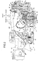
FIG. 2 ] It is a sectional view taken along the line 2-2 ofFIG. 1 . - [
FIG. 3 ] It is an enlarged view of an essential part ofFIG. 2 . - [
FIG. 4 ] It is an enlarged sectional view of a transmission case cut along a section thereof including an axis of a transmission shaft and an axis of an intermediate shaft. - [
FIG. 5 ] It is an enlarged view of a portion shown by the arrow 5 ofFIG. 3 . - [
FIG. 6 ] It is a sectional view taken along the line 6-6 ofFIG. 3 in a state where a gear cover and a fixing tool are omitted. - [
FIG. 7 ] It corresponds toFIG. 6 , and is a sectional view in a state where the fixing tool is furnished. - [
FIG. 8 ] It is a sectional view taken along the line 8-8 ofFIG. 3 for showing an attached state of the fixing tool. - Hereinafter, an embodiment of the present invention will be explained referring to the attached drawings. Also, in the explanation below, the front, rear, left, right, upward, and downward are to be directions as viewed by an occupant riding on a two-wheeled motor vehicle (scooter).
- As shown in
FIG. 1 , a two-wheeled motor vehicle B that is a saddle-ride type vehicle includes abody frame 11. Here, apivot frame 11a and arear frame 11b are illustrated, thepivot frame 11a and therear frame 11b configuring thebody frame 11, therear frame 11b extending upward to the rear from thepivot frame 11a. Above therear frame 11b, ariding seat 12 is supported by thebody frame 11. Below therear frame 11b, arear wheel unit 13 is connected to thepivot frame 11a in an up-down swingable manner. Therear wheel unit 13 includes a rear wheel WR and apower unit 15, the rear wheel WR rotating around anaxle 14, theaxle 14 extending horizontally in a vehicle width direction, thepower unit 15 generating power that drives the rear wheel WR. Arear cushion unit 16 is disposed between therear wheel unit 13 and therear frame 11b. Therear cushion unit 16 absorbs up-down motion of the rear wheel WR with respect to therear frame 11b. - The
power unit 15 includes a water-cooledengine 17 that is a power source, anintake device 18, and apower transmission device 21, theintake device 18 being connected to theengine 17 and supplying air to theengine 17, thepower transmission device 21 being stored in a transmission case (external case) 19 that is fixed to theengine 17. Theaxle 14 of the rear wheel WR is supported at both ends by of thetransmission case 19 and a support arm which will be described below. The power from theengine 17 is transmitted to the rear wheel WR through thepower transmission device 21. Theengine 17 includes anengine body 23 and acrankshaft 24, theengine body 23 including acrankcase 22, thecrankshaft 24 being rotatably supported by thecrankcase 22 and having an axis along the vehicle width direction. Theintake device 18 includes anair cleaner 25 that is joined to an upper part of thetransmission case 19. Theair cleaner 25 is connected to acylinder head 26 of theengine body 23, and has a function of removing dust from the air that is supplied to a combustion chamber of theengine body 23. - As shown in
FIG. 2 , thepower transmission device 21 includes a belt-type continuouslyvariable transmission 28, a centrifugaltype startup clutch 29, and amechanical transmission 32, the belt-type continuouslyvariable transmission 28 transmitting rotational power of thecrankshaft 24 to atransmission shaft 27 while changing the rotational speed of thecrankshaft 24 in a continuously variable manner, thestartup clutch 29 being interposed between thetransmission shaft 27 and the belt-type continuouslyvariable transmission 28, themechanical transmission 32 being arranged between thetransmission shaft 27 and theaxle 14 of the rear wheel WR, transmitting the rotational power from thetransmission shaft 27 to anintermediate shaft 31 while switching the gear shift stage between a high-speed stage and a low-speed stage, and transmitting the rotational power from theintermediate shaft 31 to theaxle 14 while reducing the speed. Thetransmission shaft 27, theintermediate shaft 31, and theaxle 14 have axes that are parallel to each other. Anoutput gear 33 is cut in theintermediate shaft 31. Theoutput gear 33 meshes with a drivengear 34 that is fixed to theaxle 14. - The rear wheel WR includes a
wheel hub 35, awheel rim 37, and a connectingportion 38, thewheel hub 35 being supported by theaxle 14 in a relatively non-rotatable manner, thewheel rim 37 being coaxially disposed to thewheel hub 35 and retaining atire 36 in a coaxial manner with thewheel hub 35, the connectingportion 38 connecting thewheel hub 35 and thewheel rim 37 with each other. Themechanical transmission 32 is disposed in a space between the connectingportion 38 and the belt-type continuouslyvariable transmission 28 in the vehicle width direction. - The front end in a vehicle longitudinal direction of a
support arm 39 is fastened to thecrankcase 22 of theengine body 23. Afirst bearing 41 is supported by thesupport arm 39, thefirst bearing 41 being connected to one end of theaxle 14 at the inner ring. Thefirst bearing 41 connects theaxle 14 to thesupport arm 39 in a rotatable manner. Thefirst bearing 41 is configured with a ball bearing for example. Between thefirst bearing 41 and thewheel hub 35, aspacer 42 is furnished on theaxle 14. Between thewheel hub 35 and thesupport arm 39, thespacer 42 forms a disposal space for abrake disk 43. - At an end surface of the
wheel hub 35, an annular protrudingportion 44 that is coaxial with theaxle 14 is arranged integrally. Thebrake disk 43 is fastened to the annular protrudingportion 44 by a plurality ofbolts 45. According to the present embodiment, adrum brake 46 for parking is disposed between thesupport arm 39 and thewheel hub 35. Thedrum brake 46 includes abrake drum 47 that is fixed to thespacer 42. However, thisdrum brake 46 may be omitted. - The
transmission case 19 includes a casemain body 48, acover member 51, and agear cover 53, the casemain body 48 continuing from thecrankcase 22 and extending rearward on the lateral side of the rear wheel WR, thecover member 51 being joined to the casemain body 48 and forming, between thecover member 51 and the outward surface of the casemain body 48, a belt-type continuouslyvariable transmission chamber 49 that stores the belt-type continuouslyvariable transmission 28, thegear cover 53 being joined to the casemain body 48, extending along the outer shape of the rear wheel WR, and forming, between thegear cover 53 and the inward surface of the casemain body 48, amechanical transmission chamber 52 that stores themechanical transmission 32. - The
gear cover 53 includes asecond bearing housing 55 of a bottomed cylindrical body, athird bearing housing 57 of a bottomed cylindrical body, and a fourth bearinghousing 59 of a through cylindrical body, the second bearinghousing 55 supporting asecond bearing 54 that is joined to one end of thetransmission shaft 27 at the inner ring, the third bearinghousing 57 supporting athird bearing 56 that is joined to one end of theintermediate shaft 31 at the inner ring, the fourth bearinghousing 59 supporting afourth bearing 58 that is joined to an intermediate position of theaxle 14 at the inner ring. Thesecond bearing 54 rotatably connects thetransmission shaft 27 to thegear cover 53. Thethird bearing 56 rotatably connects theintermediate shaft 31 to thegear cover 53. Thefourth bearing 58 rotatably connects theaxle 14 to thegear cover 53. Here, thesecond bearing 54, thethird bearing 56, and thefourth bearing 58 are configured with ball bearings.Seal members housing 59, theseal members housing 59 and theaxle 14. A storage space of thefourth bearing 58 is partitioned between theseal members gear cover 53, a protrudingportion 63 is partitioned, the protrudingportion 63 protruding toward the inside of themechanical transmission chamber 52 corresponding to the annular ridge line of the wheel rim 37 of the rear wheel WR. A surface of the protrudingportion 63 has a curved shape in the inside of themechanical transmission chamber 52. - The case
main body 48 includes a fifth bearinghousing 65 of a through cylindrical body, a sixth bearinghousing 67 of a bottomed cylindrical body, and a seventh bearinghousing 69 of a bottomed cylindrical body, the fifth bearinghousing 65 supporting afifth bearing 64 that is joined to an intermediate position of thetransmission shaft 27 at the inner ring, the sixth bearinghousing 67 supporting asixth bearing 66 that is joined to the other end of theintermediate shaft 31 at the inner ring, the seventh bearinghousing 69 supporting aseventh bearing 68 that is joined to one end of theaxle 14 at the inner ring. Thefifth bearing 64 rotatably connects thetransmission shaft 27 to the casemain body 48. Thesixth bearing 66 rotatably connects theintermediate shaft 31 to the casemain body 48. Theseventh bearing 68 rotatably connects theaxle 14 to the casemain body 48. Thus, thetransmission shaft 27 is supported at both ends by of thesecond bearing 54 and thefifth bearing 64. Theintermediate shaft 31 is supported at both ends by of thethird bearing 56 and thesixth bearing 66. Theaxle 14 is supported at both ends by of thefourth bearing 58 and theseventh bearing 68. Here, thefifth bearing 64 and theseventh bearing 68 are configured with ball bearings, and thesixth bearing 66 is configured with a needle bearing. A seal member 71 formed in an annular shape is incorporated in the fifth bearinghousing 65, the seal member 71 ensuring liquid-tightness between the fifth bearinghousing 65 and thetransmission shaft 27. - The belt-type continuously
variable transmission 28 includes adrive pulley 72, afollower pulley 73, and a V-belt 74 formed in an annular shape, thedrive pulley 72 being disposed inside the belt-type continuouslyvariable transmission chamber 49 and being connected to one end of thecrankshaft 24, thefollower pulley 73 being supported in a relatively rotatable manner by thetransmission shaft 27 that has an axis parallel to thecrankshaft 24, the V-belt 74 being wound around thedrive pulley 72 and thefollower pulley 73. Thecrankshaft 24 protrudes from thecrankcase 22, and enters the belt-type continuouslyvariable transmission chamber 49. - The
drive pulley 72 includes a fixedpulley half body 75a and a movablepulley half body 75b, the fixedpulley half body 75a being fixed to thecrankshaft 24, the movablepulley half body 75b being relatively displaceable in the axial direction with respect to the fixedpulley half body 75a. The movablepulley half body 75b is driven in the axial direction by a centrifugal force applied to aweight roller 77 that is disposed between aramp plate 76 and the movablepulley half body 75b, theramp plate 76 being fixed to thecrankshaft 24. The V-belt 74 is wound between the fixedpulley half body 75a and the movablepulley half body 75b. - The
follower pulley 73 includes aninner cylinder 78 of a cylindrical body, a fixedpulley half body 79a, anouter cylinder 81, and a movablepulley half body 79b, theinner cylinder 78 being furnished to thetransmission shaft 27 in a relatively rotatable manner and in a coaxial manner with thetransmission shaft 27, the fixedpulley half body 79a being fixed to theinner cylinder 78, theouter cylinder 81 being furnished to theinner cylinder 78 so as to be relatively displaceable in the axial direction and be relatively rotatable with respect to theinner cylinder 78, the movablepulley half body 79b being fixed to theouter cylinder 81 and supported by theinner cylinder 78 so as to be displaceable in the axial direction with respect to the fixedpulley half body 79a. The V-belt 74 is wound between the fixedpulley half body 79a and the movablepulley half body 79b. Between theinner cylinder 78 and theouter cylinder 81, atorque cam mechanism 82 is incorporated, thetorque cam mechanism 82 exerting a drive force to the movablepulley half body 79b in the axial direction according to the relative rotational phase difference between the movablepulley half body 79b and the fixedpulley half body 79a. The movablepulley half body 79b is pressed elastically to the fixedpulley half body 79a by acoil spring 83. - As shown in
FIG. 3 , thestartup clutch 29 includes a clutch outer 84, a clutch inner 85,centrifugal weights 87, andclutch springs 88, the clutch outer 84 being fixed to thetransmission shaft 27 and formed into a bowl shape, the clutch inner 85 being fixed to theinner cylinder 78, thecentrifugal weights 87 being rotatably supported aroundshafts 86 at plural positions of the clutch inner 85, the clutch springs 88 being arranged between respectivecentrifugal weights 87 and the clutch inner 85. When a rotational drive force is transmitted from the belt-type continuouslyvariable transmission 28 and the clutch inner 85 rotates, respectivecentrifugal weights 87 open to the centrifugal direction resisting the elastic force of the clutch springs 88 by action of the centrifugal force. When the rotational speed of theengine 17 reaches equal to or higher than a predetermined startup rotational speed, the centrifugal force applied to eachcentrifugal weight 87 surpasses the spring force of theclutch spring 88, the tip ends of thecentrifugal weights 87 having opened is in contact with the inner periphery of the clutch outer 84, and frictional connection is established. According to establishment of the friction connection, theinner cylinder 78 namely the fixedpulley half body 79a and the clutch outer 84 namely thetransmission shaft 27 are joined to each other. - The
mechanical transmission 32 includes aplanetary gear mechanism 89, a firstpower transmission gear 93, a secondpower transmission gear 94, and ashift clutch 96, theplanetary gear mechanism 89 being furnished to theintermediate shaft 31, the firstpower transmission gear 93 being joined to thetransmission shaft 27 in a relatively non-rotatable manner and connected to aring gear 92 of theplanetary gear mechanism 89, the secondpower transmission gear 94 being furnished to thetransmission shaft 27 in a relatively rotatable manner and connected to asun gear 91 of theplanetary gear mechanism 89, the shift clutch 96 being combined to a one-way clutch 95 and switching the gear shift stage between the low-speed stage and the high-speed stage, the one-way clutch 95 being joined to the secondpower transmission gear 94. - With reference also to
FIG. 4 , theplanetary gear mechanism 89 includes thesun gear 91, thering gear 92, a plurality ofplanetary gears 97, and aplanetary carrier 98, thesun gear 91 being supported by theintermediate shaft 31 in a relatively rotatable manner and having external teeth that are coaxially and annularly disposed to theintermediate shaft 31, thering gear 92 being supported by theintermediate shaft 31 in a relatively rotatable manner so as to surround thesun gear 91 and having internal teeth that are coaxially and annularly disposed to theintermediate shaft 31, theplanetary gears 97 having rotational axes parallel to the axis of theintermediate shaft 31 and meshing with the external teeth of thesun gear 91 and the internal teeth of thering gear 92, theplanetary carrier 98 being supported by theintermediate shaft 31 in a relatively non-rotatable manner and rotatably supporting the planetary gears 97. - On the outer periphery of the
ring gear 92, a thirdpower transmission gear 101 is formed integrally. The thirdpower transmission gear 101 meshes with the firstpower transmission gear 93. Therefore, rotational power is transmitted from thetransmission shaft 27 to thering gear 92 according to the gear ratio of the firstpower transmission gear 93 and the thirdpower transmission gear 101. - The
planetary carrier 98 includes aboss 102 formed in a cylindrical shape, theboss 102 being furnished to theintermediate shaft 31 in a coaxial manner with theintermediate shaft 31. Theboss 102 is joined to theintermediate shaft 31 in a relatively non-rotatable manner by a spline of the inner side. Therefore, theplanetary carrier 98 rotates along with theintermediate shaft 31. - The
sun gear 91 is coaxially formed to theintermediate shaft 31 and connected to atubular body 103 that is furnished to theboss 102 of theplanetary carrier 98 in a coaxial manner and in a relatively rotatable manner. On thetubular body 103, a fourthpower transmission gear 104 is formed integrally, the fourthpower transmission gear 104 meshing with the secondpower transmission gear 94. Thesun gear 91 is joined to thetubular body 103 in a relatively non-rotatable manner by a spline for example. Therefore, the fourthpower transmission gear 104 and thesun gear 91 rotate integrally. The fourthpower transmission gear 104 has the same diameter and the same number of teeth as the thirdpower transmission gear 101. - In such
planetary gear mechanism 89, when thetransmission shaft 27 rotates according to the rotational power of theengine 17, a rotational force is transmitted from the firstpower transmission gear 93 to the thirdpower transmission gear 101, and thering gear 92 rotates around the axis of theintermediate shaft 31 reversely to the rotational direction of thetransmission shaft 27. A rotational force is applied to theplanetary gears 97 in the same direction as the rotational direction of thering gear 92. A rotational force is applied to thesun gear 91 in the same direction as the rotational direction of thetransmission shaft 27. - At this time, when the
shift clutch 96 is in a disconnected state, a clutch outer 107 is supported on thetransmission shaft 27 in a relatively rotatable manner. Power is not transmitted to the clutch outer 107 from thetransmission shaft 27. Therefore, a rotational force in a direction reverse to the rotational direction of thetransmission shaft 27 is applied to the clutch outer 107 from the fourthpower transmission gear 104 that rotates integrally with thesun gear 91. Rotation of the clutch outer 107 is hindered by the one-way clutch 95. As a result, thesun gear 91 becomes a stationary state. With respect to thesun gear 91 having stopped, the rotational force of theplanetary gear 97 causes rotation of theplanetary carrier 98 around theintermediate shaft 31. Thus, a rotational driving force is transmitted to theintermediate shaft 31 from thetransmission shaft 27 with a preset reduction ratio. Rotation of theintermediate shaft 31 is transmitted to theaxle 14 of the rear wheel WR through theoutput gear 33 and the drivengear 34. "low-speed stage (LOW)" is established in themechanical transmission 32. - When the rotational speed of the
transmission shaft 27 increases and theshift clutch 96 comes into a connected state, a rotational force is applied to the clutch outer 107 from thetransmission shaft 27 through a clutch inner 108 in the same direction as the rotational direction of thetransmission shaft 27. At this time, restriction by the one-way clutch 95 is released in the clutch outer 107 of theshift clutch 96. The clutch outer 107 rotates along with thetransmission shaft 27. Rotation of the clutch outer 107 causes rotation of thesun gear 91 through the secondpower transmission gear 94 and the fourthpower transmission gear 104. Thesun gear 91 rotates in the same direction as the rotational direction of thering gear 92. In theplanetary gear mechanism 89, rotation difference for each gear is cancelled. Theplanetary carrier 98 rotates around theintermediate shaft 31 at a speed equal to that of thering gear 92 and thesun gear 91. As a result, "high-speed stage (HIGH)" is established in themechanical transmission 32. Also, in themechanical transmission 32, switching of the gear shift stage is effected in a state where the gear ratio in the belt-type continuouslyvariable transmission 28 is low. - As shown in
FIG. 5 , the secondpower transmission gear 94 is furnished to thetransmission shaft 27 in a relatively rotatable manner, and includes acylindrical body 105 that is coaxial with thetransmission shaft 27. Thecylindrical body 105 is supported by thetransmission shaft 27 through aneighth bearing 106 that is a needle bearing. The secondpower transmission gear 94 has the same diameter (D1=D2) and the same number of teeth as the firstpower transmission gear 93. - The
shift clutch 96 includes the clutch outer 107, the clutch inner 108,centrifugal weights 111, and clutch springs (not illustrated), the clutch outer 107 being supported by thetransmission shaft 27 in a relatively rotatable manner and formed into a bowl shape, the clutch inner 108 being connected to thetransmission shaft 27 in a relatively non-rotatable manner inside the clutch outer 107, thecentrifugal weights 111 being rotatably supported aroundshafts 109 at plural positions of the clutch inner 108, the clutch springs 88 being arranged between respectivecentrifugal weights 111 and theclutch inner 108. The clutch outer 107 is joined to thecylindrical body 105 of the secondpower transmission gear 94 in a relatively non-rotatable manner. Therefore, the secondpower transmission gear 94 and the clutch outer 107 rotate integrally around the axis of thetransmission shaft 27. The firstpower transmission gear 93, thecylindrical body 105 of the secondpower transmission gear 94, and the clutch inner 108 are sandwiched between the step of thetransmission shaft 27 and thesecond bearing 54, and restricted in the axial direction of thetransmission shaft 27 in a state of not being relatively displaceable. - In this shift clutch 96, when the clutch inner 108 rotates along with the
transmission shaft 27, respectivecentrifugal weights 111 open toward the centrifugal direction resisting the elastic force of the clutch springs by action of the centrifugal force. When the rotational speed of the clutch inner 108 becomes equal to or higher than a predetermined rotational speed, the centrifugal force applied to eachcentrifugal weight 111 surpasses the spring force of the clutch spring, and thecentrifugal weights 111 effect frictional engagement with the inner periphery of the clutch outer 107. According to establishment of the frictional engagement, the clutch outer 107 and the secondpower transmission gear 94 rotate along with thetransmission shaft 27. - Here, the connection rotational speed at which the
shift clutch 96 comes from the disconnected state into the connected state is higher than the connection rotational speed at which thestartup clutch 29 comes from the disconnected state into the connected state, and the disconnection rotational speed at which theshift clutch 96 comes from the connected state into the disconnected state is also higher than the disconnection rotational speed at which thestartup clutch 29 comes from the connected state into the disconnected state. - As shown in
FIG. 6 , the one-way clutch 95 includes aninner ring 112, anouter ring 113, and a plurality ofroller cams 114, theinner ring 112 being furnished to thetransmission shaft 27 in a coaxial manner with thetransmission shaft 27, theouter ring 113 being coaxially disposed to theinner ring 112 and relatively rotating with respect to theinner ring 112, theroller cams 114 being disposed between theinner ring 112 and theouter ring 113. In theroller cam 114, a cam surface is formed. When theouter ring 113 rotates toward the first direction around the axis of thetransmission shaft 27 with respect to theinner ring 112, the cam surface establishes the connected state between theinner ring 112 and theouter ring 113 with theroller cams 114 being bitten between theinner ring 112 and theouter ring 113 to prevent relative rotation of theouter ring 113 with respect to theinner ring 112. When theouter ring 113 rotates toward the second direction that is opposite to the first direction around the axis of thetransmission shaft 27 with respect to theinner ring 112, the cam surface allows slippage of theouter ring 113, and establishes the disconnected state between theinner ring 112 and theouter ring 113. Here, theinner ring 112 is immovably fixed. Therefore, even if a rotational force is applied to theouter ring 113 in the first direction, theouter ring 113 is restricted with respect to theinner ring 112 according to biting of theroller cams 114, and rotation of theouter ring 113 is prevented. On the other hand, when a rotational force is applied in the second direction, theroller cams 114 are not bitten, and theouter ring 113 runs idle with respect to theinner ring 112. - As shown in
FIG. 7 , theinner ring 112 is fixed to the casemain body 48 of thetransmission case 19 by afixing tool 115. The fixingtool 115 includes asupport body 116 and acover 118, thesupport body 116 being formed into an annular plate shape surrounding the outer periphery of theouter ring 113, thecover 118 being joined to thesupport body 116 and theinner ring 112 so as to fix theinner ring 112 to thesupport body 116, including acutout portion 117, and covering theroller cams 114 and theouter ring 113, a part of theouter ring 113 facing thecutout portion 117 over a predetermined central angle. In thesupport body 116, three attachingarm portions 119 are formed, the attachingarm portions 119 expanding outward. The attachingarm portions 119 are laid over the casemain body 48. Thecover 118 is formed into an annular shape surrounding theinner ring 112 and welded to theinner ring 112 over the entire periphery of theinner ring 112. The outer periphery of thecover 118 is welded and fixed to thesupport body 116 excepting thecutout portion 117. As viewed along the axial direction of theouter ring 113 and theinner ring 112, thecutout portion 117 has an arc shape that has the center of curvature at anaxis 27a of thetransmission shaft 27, by reflecting the shape of the protrudingportion 63. - As shown in
FIG. 8 , acollar 121 and the attachingarm portions 119 of thefixing tool 115 are laid in this order over amating surface 48a of the casemain body 48. Themating surface 48a is orthogonal to theaxis 27a of thetransmission shaft 27. Thegear cover 53 is joined to themating surface 48a of the casemain body 48. In joining, a plurality ofbolts 122 are used. Thebolts 122 penetrate the casemain body 48, and are screwed intoscrew holes 123 of thegear cover 53. The attachingarm portions 119 and thecollar 121 are sandwiched between thegear cover 53 and the casemain body 48. Thebolts 122 and the screw holes 123 have axes parallel to theaxis 27a of thetransmission shaft 27. Thus, the fixingtool 115 is fixed in the axial direction of thetransmission shaft 27. -
Support tubes 124 formed in a cylindrical shape are fitted into themating surface 48a of the casemain body 48. In themating surface 48a, bottomedholes 125 are defined, the bottomedholes 125 receiving thesupport tubes 124. The bottomedhole 125 defines a cylindrical space that has an axis orthogonal to themating surface 48a. A rubber 126 is baked to be attached to the outer peripheral surface of thesupport tube 124 over the entire region. Thesupport tubes 124 penetrate thecollar 121, and are fitted to supportholes 119a of the attachingarm portions 119. Thus, the fixingtool 115 is immovably supported around theaxis 27a of thetransmission shaft 27. - With reference to
FIG. 5 , theinner ring 112 of the one-way clutch 95 is supported by thecylindrical body 105 of the secondpower transmission gear 94 in a relatively rotatable manner through aninth bearing 120 that is a needle bearing. Theouter ring 113 of the one-way clutch 95 is fixed to the clutch outer 107. Therefore, theouter ring 113 rotates integrally with the clutch outer 107. In the one-way clutch 95, when a rotational force is applied to the clutch outer 107 in the direction opposite to the rotational direction of thetransmission shaft 27, theroller cams 114 are bitten between theinner ring 112 and theouter ring 113, and the connected state is established between the fixingtool 115 and the clutch outer 107. According to biting of theroller cams 114, theouter ring 113 is restricted with respect to theinner ring 112, and rotation of theouter ring 113 is controlled. When a rotational force is applied to the clutch outer 107 in the same direction as the rotational direction of thetransmission shaft 27, theroller cams 114 allow slippage of theouter ring 113, and the disconnected state is established between the fixingtool 115 and the clutch outer 107. Biting of theroller cams 114 does not occur, and the clutch outer 107 runs idle with respect to thefixing tool 115. Rotation of the clutch outer 107 is allowed. - With reference to
FIG. 4 to FIG. 6 , in themechanical transmission 32, anoil supply mechanism 127 is incorporated, theoil supply mechanism 127 supplying oil as a lubricating oil to movable bodies. The oil supply mechanism 127 includes a first oil passage 128, a second oil passage 129, a third oil passage 131, a fourth oil passage 132, a fifth oil passage 133, an oil receiver 134 formed in a gutter-shape, a first oil supply passage 135, and a second oil supply passage 136, the first oil passage 128 being formed in the transmission shaft 27 and extending in the axial direction from the end surface on the second bearing 54 side, the second oil passage 129 extending from the first oil passage 128 in the radial direction of the transmission shaft 27 and opening to the outer peripheral surface of the transmission shaft 27 toward the eighth bearing 106, the third oil passage 131 being formed in the intermediate shaft 31 and penetrating the intermediate shaft 31 in the axial direction from the end surface on the sixth bearing 66 side to the end surface on the third bearing 56 side, the fourth oil passage 132 extending from the third oil passage 131 in the radial direction of the intermediate shaft 31 and opening to the outer peripheral surface of the intermediate shaft 31 in a sliding region between the boss 102 and the tubular body 103, the fifth oil passage 133 extending from the third oil passage 131 in the radial direction of the intermediate shaft 31 and opening to the outer peripheral surface of the intermediate shaft 31 in a sliding region between the intermediate shaft 31 and the ring gear 92, the oil receiver 134 being formed in the case main body 48 and the gear cover 53 above the transmission shaft 27 and the intermediate shaft 31 and receiving the oil scraped up by the first to fourth power transmission gears 93, 94, 101, 104, the first oil supply passage 135 being formed in the gear cover 53, extending from the oil receiver 134 downward in the gravitational direction, and being connected to the first oil passage 128 in the second bearing housing 55, the second oil supply passage 136 being formed in the case main body 48, extending from the oil receiver 134 downward in the gravitational direction, and being connected to the third oil passage 131 in the sixth bearing housing 67. In thecylindrical body 105 of the secondpower transmission gear 94, asixth oil passage 137 is defined, thesixth oil passage 137 penetrating in the radial direction and opening to the inner peripheral surface and the outer peripheral surface of thecylindrical body 105. - Inside the
mechanical transmission chamber 52, oil accumulates at the bottom by action of the gravity. The oil having accumulated is agitated by the first and second power transmission gears 93, 94 on therotating transmission shaft 27 and the third and fourth power transmission gears 101, 104 on the rotatingintermediate shaft 31, and splatters inside themechanical transmission chamber 52. The splattering oil is collected by theoil receiver 134, and is supplied to theeighth bearing 106 through the firstoil supply passage 135, thefirst oil passage 128, and thesecond oil passage 129. The oil having lubricated theeighth bearing 106 is supplied to theninth bearing 120 further going through thesixth oil passage 137. In a similar manner, the oil having been collected is supplied to the sliding region between theboss 102 and thetubular body 103 through the secondoil supply passage 136, thethird oil passage 131, and thefourth oil passage 132, and is supplied to the sliding region of thering gear 92 through the secondoil supply passage 136, thethird oil passage 131, and thefifth oil passage 133. - Here, the second
oil supply passage 136 passes through the sixth bearinghousing 67 from theoil receiver 134, extends in the up-down direction, and opens to the outer surface of the casemain body 48. Such secondoil supply passage 136 can be formed by drilling from the outer surface of the casemain body 48. The lower end opening of the secondoil supply passage 136 is closed by aplug member 138 that is screwed into the casemain body 48. - As shown in
FIG. 5 , thecutout portion 117 of thefixing tool 115 is formed along the protrudingportion 63 of thegear cover 53. Thecutout portion 117 makes a part of theouter ring 113 of the one-way clutch 95 face the inner wall surface of the protrudingportion 63. Here, afirst gap 139 is formed between the fixingtool 115 and thegear cover 53, thefirst gap 139 being connected to thecutout portion 117. By rotation of the one-way clutch 95, the oil splattering from theouter ring 113 passes through thecutout portion 117 and thefirst gap 139, and is discharged to thegear cover 53 side. The oil discharge structure is configured with thecutout portion 117 and thefirst gap 139. - A
second gap 141 is formed between the clutch outer 107 and theinner ring 112. Thesecond gap 141 connects a space on the inner side and a space on the outer side of theinner ring 112 to each other. Therefore, the oil having lubricated theninth bearing 120 flows out from thesecond gap 141 toward thefirst gap 139 according to the centrifugal force of the clutch outer 107. - Next, the operation of this embodiment will be explained. The oil discharge structure of the one-way clutch 95 includes the fixing
tool 115 that is fixed to thetransmission case 19, thetransmission case 19 storing the one-way clutch 95 in the inside, the fixingtool 115 includes thecutout portion 117 that is formed along the protrudingportion 63 of thetransmission case 19, thefirst gap 139 is formed between thecutout portion 117 and the protrudingportion 63, and the oil flowing out by rotation of theouter ring 113 of the one-way clutch 95 passes through thecutout portion 117 and thefirst gap 139, and is discharged to thegear cover 53 side. Since the protrudingportion 63 is arranged close to thecutout portion 117, the oil vigorously discharged from thecutout portion 117 is received by the protrudingportion 63, and is suppressed from splattering to the periphery. Since splattering is reduced, occurrence of air entrainment is suppressed. Even if thefixing tool 115 comes close to the protrudingportion 63, interference between the fixingtool 115 and the protrudingportion 63 is avoided by action of thecutout portion 117, and therefore thefixing tool 115 can be efficiently stored in an internal space of thetransmission case 19. Therefore, it can contribute to compactization of thetransmission case 19. - As described above, since the protruding
portion 63 has an arc shape as viewed along the axial direction of thetransmission shaft 27, the protrudingportion 63 can receive the oil that has been vigorously discharged in any radial direction. Furthermore, since the protrudingportion 63 has a curved shape, the oil having been vigorously discharged can be received without splattering. - The one-way clutch 95 is configured with the
outer ring 113 and theinner ring 112, theouter ring 113 being rotatable, rotation of theinner ring 112 being restricted, and thefixing tool 115 fixes theinner ring 112 while covering at least a part of theouter ring 113. Since a part of the rotatingouter ring 113 is covered with the fixingtool 115, the oil can be prevented from splattering. - According to this oil discharge structure, there exists the
second gap 141 between the clutch outer 107 and theinner ring 112, the clutch outer 107 rotating integrally with theouter ring 113, and the oil supplied from the inner side of theinner ring 112 is discharged through thesecond gap 141. Therefore, the oil supplied from the inner side of theinner ring 112 can be also discharged since the oil passes through thesecond gap 141. - As described above, the
power transmission device 21 includes theinner ring 112, theouter ring 113, thesupport body 116, and thecover 118, theouter ring 113 being coaxially disposed to theinner ring 112 and relatively rotating with respect to theinner ring 112, thesupport body 116 being fixed to thetransmission case 19 and surrounding the outer periphery of theouter ring 113, thetransmission case 19 storing theinner ring 112 and theout ring 113, thecover 118 being joined to thesupport body 116 and theinner ring 112 so as to fix theinner ring 112 to thesupport body 116, including thecutout portion 117 that makes a part of theouter ring 113 face the inner wall surface of thetransmission case 19, and covering the side surface of theinner ring 112 and theouter ring 113. At this time, thefirst gap 139 is formed between thecover 118 and the inner wall surface of thetransmission case 19, thefirst gap 139 being connected to thecutout portion 117. - While the
outer ring 113 rotates, the oil splattering outward in the radial direction from theouter ring 113 is vigorously discharged outward from thecutout portion 117. The oil having discharged from thecutout portion 117 hits and is received by the inner surface wall of thetransmission case 19. The oil flows along the inner surface wall of thetransmission case 19 from thefirst gap 139, and is collected efficiently. Since splattering of the oil is reduced, occurrence of air entrainment is suppressed. Also, thetransmission case 19 can come close to theouter ring 113 as much as possible by action of thecutout portion 117. Therefore, it can contribute to compactization of thetransmission case 19. - The embodiment of the present invention has been explained above. However, the present invention is not limited to the embodiment described above, and various design changes can be effected without departing from the gist of the present invention.
To provide an oil discharge structure of a rotational body capable of effectively suppressing occurrence of air entrainment.
The oil discharge structure of arotational body 95 includes afixing tool 115 that is fixed to anexternal case 53, theexternal case 53 storing therotational body 95 in an inside thereof in a rotatable manner. The fixingtool 115 includes acutout portion 117 that is formed along a protrudingportion 63 of theexternal case 53, afirst gap 139 is formed between thecutout portion 117 and the protrudingportion 63, and oil flowing out by rotation of therotational body 95 passes through thecutout portion 117 and thefirst gap 139 so as to be discharged to theexternal case 53 side -
- 19
- External case (transmission case)
- 63
- Protruding portion
- 95
- Rotational body (one-way clutch)
- 107
- Rotational portion (clutch outer)
- 112
- Inner ring
- 113
- Outer ring
- 115
- Fixing tool
- 117
- Cutout portion
- 139
- First gap
- 141
- Second gap
Claims (5)
- An external case comprising a gear cover (53) and equipped with a rotational body (95) and an oil discharge structure (117, 13) therein,
wherein a protruding portion (63) is formed in the external case (19),
the rotational body (95) is provided inside the external case (19) in a rotatable manner, and
a fixing tool (115) is fixed to the external case (19),
characterized in that the fixing tool (115) includes a cutout portion (117) that is formed along a the protruding portion (63) of the external case (19),
the oil discharge structure comprises the cutout portion (117) and a first gap (139) which is formed between the cutout portion (117) and the protruding portion (63), and
the oil discharge structure permits oil flowing out by rotation of the rotational body (95) to pass through the cutout portion (117) and the first gap (139) so as to be discharged to the gear cover (53) side. - The external case according to claim 1, wherein the protruding portion (63) has an arc shape as viewed in an axial direction of the rotational body (95).
- The external case according to claim 1 or 2, wherein the protruding portion (63) has a surface of a curved shape.
- The external case according to any one of claims 1 to 3,
wherein the rotational body (95) is configured with an outer ring (113) and an inner ring (112), the outer ring (113) being rotatable, rotation of the inner ring (112) being restricted, and
the fixing tool (115) fixes the inner ring (112) while covering at least a part of the outer ring (113). - The external case according to claim 4,
wherein a second gap (141) exists between a rotational portion (107) and the inner ring (112), the rotational portion (107) rotating integrally with the outer ring (113), and
oil supplied from an inner side of the inner ring (112) is discharged through the second gap (141).
Applications Claiming Priority (1)
| Application Number | Priority Date | Filing Date | Title |
|---|---|---|---|
| JP2016238532A JP6499143B2 (en) | 2016-12-08 | 2016-12-08 | Oil discharge structure of rotating body |
Publications (2)
| Publication Number | Publication Date |
|---|---|
| EP3333460A1 EP3333460A1 (en) | 2018-06-13 |
| EP3333460B1 true EP3333460B1 (en) | 2019-07-10 |
Family
ID=60268262
Family Applications (1)
| Application Number | Title | Priority Date | Filing Date |
|---|---|---|---|
| EP17200081.2A Active EP3333460B1 (en) | 2016-12-08 | 2017-11-06 | Oil discharge structure of rotational body |
Country Status (2)
| Country | Link |
|---|---|
| EP (1) | EP3333460B1 (en) |
| JP (1) | JP6499143B2 (en) |
Families Citing this family (1)
| Publication number | Priority date | Publication date | Assignee | Title |
|---|---|---|---|---|
| JP2021110359A (en) * | 2020-01-08 | 2021-08-02 | Nskワーナー株式会社 | Ratchet type clutch |
Family Cites Families (6)
| Publication number | Priority date | Publication date | Assignee | Title |
|---|---|---|---|---|
| US3466947A (en) * | 1967-11-08 | 1969-09-16 | Gen Motors Corp | Releasable one-way device and transmission |
| JPS5919139Y2 (en) * | 1979-09-13 | 1984-06-02 | アイシン・ワ−ナ−株式会社 | one way clutch |
| JPS59136069U (en) * | 1983-03-01 | 1984-09-11 | トヨタ自動車株式会社 | Oil circulation device for manual gear transmission |
| JP2002310200A (en) * | 2001-04-12 | 2002-10-23 | Nsk Warner Kk | One-way clutch assembly |
| JP6439995B2 (en) * | 2014-10-31 | 2018-12-26 | 愛知機械工業株式会社 | Transmission case and transmission including the same |
| EP3184414B1 (en) * | 2015-12-25 | 2018-02-28 | Honda Motor Co., Ltd. | Power transmission device for saddle-ridden vehicle |
-
2016
- 2016-12-08 JP JP2016238532A patent/JP6499143B2/en active Active
-
2017
- 2017-11-06 EP EP17200081.2A patent/EP3333460B1/en active Active
Non-Patent Citations (1)
| Title |
|---|
| None * |
Also Published As
| Publication number | Publication date |
|---|---|
| JP6499143B2 (en) | 2019-04-10 |
| EP3333460A1 (en) | 2018-06-13 |
| JP2018096396A (en) | 2018-06-21 |
Similar Documents
| Publication | Publication Date | Title |
|---|---|---|
| US20170305499A1 (en) | Adjustable friction ring transmission for a vehicle operable using motor power and/or pedal power | |
| US8836181B2 (en) | Vehicle drive device | |
| US9644531B2 (en) | Hybrid drive device | |
| JP5506601B2 (en) | Continuously variable transmission structure | |
| EP1455085A2 (en) | Automotive internal combustion engine control system | |
| CN101244748B (en) | Power unit and straddle-type vehicle | |
| EP3718806B1 (en) | Hybrid vehicle | |
| US8464681B2 (en) | Power unit for vehicle | |
| EP3514400B1 (en) | Multiplate friction clutch | |
| JP2007113683A (en) | Lubrication structure of device for shifting forward/reverse gears | |
| EP3333460B1 (en) | Oil discharge structure of rotational body | |
| JP6238357B2 (en) | Power transmission device for saddle-ride type vehicles | |
| JP6103431B2 (en) | Power transmission device for saddle-ride type vehicles | |
| JP5654389B2 (en) | Continuous transmission structure | |
| JP5072672B2 (en) | Lubricating structure of planetary gear unit | |
| US6945902B2 (en) | Output shaft supporting apparatus for automatic transmission | |
| US20100229816A1 (en) | Power unit for vehicle | |
| EP2546550B1 (en) | Transmission apparatus and saddle type vehicle including the same | |
| JP5506602B2 (en) | Continuously variable transmission structure | |
| KR20050033834A (en) | Automatic two-wheel vehicle | |
| EP3339687A1 (en) | Planetary gear device | |
| EP2551551B1 (en) | Power unit for small vehicle | |
| JP5688482B2 (en) | Continuously variable transmission structure | |
| JP2022168660A (en) | Rotary electric machine cooling structure | |
| JP3703177B2 (en) | Automotive transfer equipment |
Legal Events
| Date | Code | Title | Description |
|---|---|---|---|
| PUAI | Public reference made under article 153(3) epc to a published international application that has entered the european phase |
Free format text: ORIGINAL CODE: 0009012 |
|
| STAA | Information on the status of an ep patent application or granted ep patent |
Free format text: STATUS: REQUEST FOR EXAMINATION WAS MADE |
|
| 17P | Request for examination filed |
Effective date: 20171106 |
|
| AK | Designated contracting states |
Kind code of ref document: A1 Designated state(s): AL AT BE BG CH CY CZ DE DK EE ES FI FR GB GR HR HU IE IS IT LI LT LU LV MC MK MT NL NO PL PT RO RS SE SI SK SM TR |
|
| AX | Request for extension of the european patent |
Extension state: BA ME |
|
| GRAP | Despatch of communication of intention to grant a patent |
Free format text: ORIGINAL CODE: EPIDOSNIGR1 |
|
| STAA | Information on the status of an ep patent application or granted ep patent |
Free format text: STATUS: GRANT OF PATENT IS INTENDED |
|
| RIC1 | Information provided on ipc code assigned before grant |
Ipc: F16H 57/02 20120101ALN20190118BHEP Ipc: F16H 57/04 20100101AFI20190118BHEP Ipc: F16D 41/07 20060101ALI20190118BHEP |
|
| INTG | Intention to grant announced |
Effective date: 20190206 |
|
| GRAS | Grant fee paid |
Free format text: ORIGINAL CODE: EPIDOSNIGR3 |
|
| GRAA | (expected) grant |
Free format text: ORIGINAL CODE: 0009210 |
|
| STAA | Information on the status of an ep patent application or granted ep patent |
Free format text: STATUS: THE PATENT HAS BEEN GRANTED |
|
| AK | Designated contracting states |
Kind code of ref document: B1 Designated state(s): AL AT BE BG CH CY CZ DE DK EE ES FI FR GB GR HR HU IE IS IT LI LT LU LV MC MK MT NL NO PL PT RO RS SE SI SK SM TR |
|
| REG | Reference to a national code |
Ref country code: GB Ref legal event code: FG4D |
|
| REG | Reference to a national code |
Ref country code: CH Ref legal event code: EP Ref country code: AT Ref legal event code: REF Ref document number: 1153916 Country of ref document: AT Kind code of ref document: T Effective date: 20190715 |
|
| REG | Reference to a national code |
Ref country code: DE Ref legal event code: R096 Ref document number: 602017005188 Country of ref document: DE |
|
| REG | Reference to a national code |
Ref country code: IE Ref legal event code: FG4D |
|
| REG | Reference to a national code |
Ref country code: NL Ref legal event code: MP Effective date: 20190710 |
|
| REG | Reference to a national code |
Ref country code: LT Ref legal event code: MG4D |
|
| REG | Reference to a national code |
Ref country code: AT Ref legal event code: MK05 Ref document number: 1153916 Country of ref document: AT Kind code of ref document: T Effective date: 20190710 |
|
| PG25 | Lapsed in a contracting state [announced via postgrant information from national office to epo] |
Ref country code: HR Free format text: LAPSE BECAUSE OF FAILURE TO SUBMIT A TRANSLATION OF THE DESCRIPTION OR TO PAY THE FEE WITHIN THE PRESCRIBED TIME-LIMIT Effective date: 20190710 Ref country code: AT Free format text: LAPSE BECAUSE OF FAILURE TO SUBMIT A TRANSLATION OF THE DESCRIPTION OR TO PAY THE FEE WITHIN THE PRESCRIBED TIME-LIMIT Effective date: 20190710 Ref country code: PT Free format text: LAPSE BECAUSE OF FAILURE TO SUBMIT A TRANSLATION OF THE DESCRIPTION OR TO PAY THE FEE WITHIN THE PRESCRIBED TIME-LIMIT Effective date: 20191111 Ref country code: NL Free format text: LAPSE BECAUSE OF FAILURE TO SUBMIT A TRANSLATION OF THE DESCRIPTION OR TO PAY THE FEE WITHIN THE PRESCRIBED TIME-LIMIT Effective date: 20190710 Ref country code: NO Free format text: LAPSE BECAUSE OF FAILURE TO SUBMIT A TRANSLATION OF THE DESCRIPTION OR TO PAY THE FEE WITHIN THE PRESCRIBED TIME-LIMIT Effective date: 20191010 Ref country code: LT Free format text: LAPSE BECAUSE OF FAILURE TO SUBMIT A TRANSLATION OF THE DESCRIPTION OR TO PAY THE FEE WITHIN THE PRESCRIBED TIME-LIMIT Effective date: 20190710 Ref country code: BG Free format text: LAPSE BECAUSE OF FAILURE TO SUBMIT A TRANSLATION OF THE DESCRIPTION OR TO PAY THE FEE WITHIN THE PRESCRIBED TIME-LIMIT Effective date: 20191010 Ref country code: FI Free format text: LAPSE BECAUSE OF FAILURE TO SUBMIT A TRANSLATION OF THE DESCRIPTION OR TO PAY THE FEE WITHIN THE PRESCRIBED TIME-LIMIT Effective date: 20190710 Ref country code: SE Free format text: LAPSE BECAUSE OF FAILURE TO SUBMIT A TRANSLATION OF THE DESCRIPTION OR TO PAY THE FEE WITHIN THE PRESCRIBED TIME-LIMIT Effective date: 20190710 |
|
| PG25 | Lapsed in a contracting state [announced via postgrant information from national office to epo] |
Ref country code: RS Free format text: LAPSE BECAUSE OF FAILURE TO SUBMIT A TRANSLATION OF THE DESCRIPTION OR TO PAY THE FEE WITHIN THE PRESCRIBED TIME-LIMIT Effective date: 20190710 Ref country code: LV Free format text: LAPSE BECAUSE OF FAILURE TO SUBMIT A TRANSLATION OF THE DESCRIPTION OR TO PAY THE FEE WITHIN THE PRESCRIBED TIME-LIMIT Effective date: 20190710 Ref country code: AL Free format text: LAPSE BECAUSE OF FAILURE TO SUBMIT A TRANSLATION OF THE DESCRIPTION OR TO PAY THE FEE WITHIN THE PRESCRIBED TIME-LIMIT Effective date: 20190710 Ref country code: GR Free format text: LAPSE BECAUSE OF FAILURE TO SUBMIT A TRANSLATION OF THE DESCRIPTION OR TO PAY THE FEE WITHIN THE PRESCRIBED TIME-LIMIT Effective date: 20191011 Ref country code: IS Free format text: LAPSE BECAUSE OF FAILURE TO SUBMIT A TRANSLATION OF THE DESCRIPTION OR TO PAY THE FEE WITHIN THE PRESCRIBED TIME-LIMIT Effective date: 20191110 Ref country code: ES Free format text: LAPSE BECAUSE OF FAILURE TO SUBMIT A TRANSLATION OF THE DESCRIPTION OR TO PAY THE FEE WITHIN THE PRESCRIBED TIME-LIMIT Effective date: 20190710 |
|
| PG25 | Lapsed in a contracting state [announced via postgrant information from national office to epo] |
Ref country code: TR Free format text: LAPSE BECAUSE OF FAILURE TO SUBMIT A TRANSLATION OF THE DESCRIPTION OR TO PAY THE FEE WITHIN THE PRESCRIBED TIME-LIMIT Effective date: 20190710 |
|
| PG25 | Lapsed in a contracting state [announced via postgrant information from national office to epo] |
Ref country code: EE Free format text: LAPSE BECAUSE OF FAILURE TO SUBMIT A TRANSLATION OF THE DESCRIPTION OR TO PAY THE FEE WITHIN THE PRESCRIBED TIME-LIMIT Effective date: 20190710 Ref country code: DK Free format text: LAPSE BECAUSE OF FAILURE TO SUBMIT A TRANSLATION OF THE DESCRIPTION OR TO PAY THE FEE WITHIN THE PRESCRIBED TIME-LIMIT Effective date: 20190710 Ref country code: RO Free format text: LAPSE BECAUSE OF FAILURE TO SUBMIT A TRANSLATION OF THE DESCRIPTION OR TO PAY THE FEE WITHIN THE PRESCRIBED TIME-LIMIT Effective date: 20190710 Ref country code: PL Free format text: LAPSE BECAUSE OF FAILURE TO SUBMIT A TRANSLATION OF THE DESCRIPTION OR TO PAY THE FEE WITHIN THE PRESCRIBED TIME-LIMIT Effective date: 20190710 |
|
| PG25 | Lapsed in a contracting state [announced via postgrant information from national office to epo] |
Ref country code: IS Free format text: LAPSE BECAUSE OF FAILURE TO SUBMIT A TRANSLATION OF THE DESCRIPTION OR TO PAY THE FEE WITHIN THE PRESCRIBED TIME-LIMIT Effective date: 20200224 Ref country code: CZ Free format text: LAPSE BECAUSE OF FAILURE TO SUBMIT A TRANSLATION OF THE DESCRIPTION OR TO PAY THE FEE WITHIN THE PRESCRIBED TIME-LIMIT Effective date: 20190710 Ref country code: SK Free format text: LAPSE BECAUSE OF FAILURE TO SUBMIT A TRANSLATION OF THE DESCRIPTION OR TO PAY THE FEE WITHIN THE PRESCRIBED TIME-LIMIT Effective date: 20190710 Ref country code: SM Free format text: LAPSE BECAUSE OF FAILURE TO SUBMIT A TRANSLATION OF THE DESCRIPTION OR TO PAY THE FEE WITHIN THE PRESCRIBED TIME-LIMIT Effective date: 20190710 |
|
| REG | Reference to a national code |
Ref country code: DE Ref legal event code: R097 Ref document number: 602017005188 Country of ref document: DE Ref country code: DE Ref legal event code: R119 Ref document number: 602017005188 Country of ref document: DE |
|
| PLBE | No opposition filed within time limit |
Free format text: ORIGINAL CODE: 0009261 |
|
| STAA | Information on the status of an ep patent application or granted ep patent |
Free format text: STATUS: NO OPPOSITION FILED WITHIN TIME LIMIT |
|
| PG2D | Information on lapse in contracting state deleted |
Ref country code: IS |
|
| PG25 | Lapsed in a contracting state [announced via postgrant information from national office to epo] |
Ref country code: LU Free format text: LAPSE BECAUSE OF NON-PAYMENT OF DUE FEES Effective date: 20191106 Ref country code: MC Free format text: LAPSE BECAUSE OF FAILURE TO SUBMIT A TRANSLATION OF THE DESCRIPTION OR TO PAY THE FEE WITHIN THE PRESCRIBED TIME-LIMIT Effective date: 20190710 |
|
| 26N | No opposition filed |
Effective date: 20200603 |
|
| REG | Reference to a national code |
Ref country code: BE Ref legal event code: MM Effective date: 20191130 |
|
| PG25 | Lapsed in a contracting state [announced via postgrant information from national office to epo] |
Ref country code: SI Free format text: LAPSE BECAUSE OF FAILURE TO SUBMIT A TRANSLATION OF THE DESCRIPTION OR TO PAY THE FEE WITHIN THE PRESCRIBED TIME-LIMIT Effective date: 20190710 |
|
| PG25 | Lapsed in a contracting state [announced via postgrant information from national office to epo] |
Ref country code: DE Free format text: LAPSE BECAUSE OF NON-PAYMENT OF DUE FEES Effective date: 20200603 Ref country code: FR Free format text: LAPSE BECAUSE OF NON-PAYMENT OF DUE FEES Effective date: 20191130 Ref country code: IE Free format text: LAPSE BECAUSE OF NON-PAYMENT OF DUE FEES Effective date: 20191106 |
|
| PG25 | Lapsed in a contracting state [announced via postgrant information from national office to epo] |
Ref country code: BE Free format text: LAPSE BECAUSE OF NON-PAYMENT OF DUE FEES Effective date: 20191130 |
|
| PG25 | Lapsed in a contracting state [announced via postgrant information from national office to epo] |
Ref country code: CY Free format text: LAPSE BECAUSE OF FAILURE TO SUBMIT A TRANSLATION OF THE DESCRIPTION OR TO PAY THE FEE WITHIN THE PRESCRIBED TIME-LIMIT Effective date: 20190710 |
|
| PG25 | Lapsed in a contracting state [announced via postgrant information from national office to epo] |
Ref country code: LI Free format text: LAPSE BECAUSE OF FAILURE TO SUBMIT A TRANSLATION OF THE DESCRIPTION OR TO PAY THE FEE WITHIN THE PRESCRIBED TIME-LIMIT Effective date: 20201130 Ref country code: CH Free format text: LAPSE BECAUSE OF FAILURE TO SUBMIT A TRANSLATION OF THE DESCRIPTION OR TO PAY THE FEE WITHIN THE PRESCRIBED TIME-LIMIT Effective date: 20201130 |
|
| REG | Reference to a national code |
Ref country code: CH Ref legal event code: PL |
|
| PG25 | Lapsed in a contracting state [announced via postgrant information from national office to epo] |
Ref country code: MT Free format text: LAPSE BECAUSE OF FAILURE TO SUBMIT A TRANSLATION OF THE DESCRIPTION OR TO PAY THE FEE WITHIN THE PRESCRIBED TIME-LIMIT Effective date: 20190710 Ref country code: HU Free format text: LAPSE BECAUSE OF FAILURE TO SUBMIT A TRANSLATION OF THE DESCRIPTION OR TO PAY THE FEE WITHIN THE PRESCRIBED TIME-LIMIT; INVALID AB INITIO Effective date: 20171106 |
|
| PG25 | Lapsed in a contracting state [announced via postgrant information from national office to epo] |
Ref country code: MK Free format text: LAPSE BECAUSE OF FAILURE TO SUBMIT A TRANSLATION OF THE DESCRIPTION OR TO PAY THE FEE WITHIN THE PRESCRIBED TIME-LIMIT Effective date: 20190710 |
|
| GBPC | Gb: european patent ceased through non-payment of renewal fee |
Effective date: 20211106 |
|
| PG25 | Lapsed in a contracting state [announced via postgrant information from national office to epo] |
Ref country code: GB Free format text: LAPSE BECAUSE OF NON-PAYMENT OF DUE FEES Effective date: 20211106 |
|
| PGFP | Annual fee paid to national office [announced via postgrant information from national office to epo] |
Ref country code: IT Payment date: 20231010 Year of fee payment: 7 |