EP3333440B1 - Drehmomentübertragungsvorrichtung, insbesondere für kraftfahrzeug - Google Patents
Drehmomentübertragungsvorrichtung, insbesondere für kraftfahrzeug Download PDFInfo
- Publication number
- EP3333440B1 EP3333440B1 EP17204600.5A EP17204600A EP3333440B1 EP 3333440 B1 EP3333440 B1 EP 3333440B1 EP 17204600 A EP17204600 A EP 17204600A EP 3333440 B1 EP3333440 B1 EP 3333440B1
- Authority
- EP
- European Patent Office
- Prior art keywords
- torque
- rotation
- freewheel mechanism
- actuating member
- diaphragm
- Prior art date
- Legal status (The legal status is an assumption and is not a legal conclusion. Google has not performed a legal analysis and makes no representation as to the accuracy of the status listed.)
- Not-in-force
Links
Images



Classifications
-
- F—MECHANICAL ENGINEERING; LIGHTING; HEATING; WEAPONS; BLASTING
- F16—ENGINEERING ELEMENTS AND UNITS; GENERAL MEASURES FOR PRODUCING AND MAINTAINING EFFECTIVE FUNCTIONING OF MACHINES OR INSTALLATIONS; THERMAL INSULATION IN GENERAL
- F16D—COUPLINGS FOR TRANSMITTING ROTATION; CLUTCHES; BRAKES
- F16D41/00—Freewheels or freewheel clutches
- F16D41/04—Freewheels or freewheel clutches combined with a clutch for locking the driving and driven members
-
- F—MECHANICAL ENGINEERING; LIGHTING; HEATING; WEAPONS; BLASTING
- F16—ENGINEERING ELEMENTS AND UNITS; GENERAL MEASURES FOR PRODUCING AND MAINTAINING EFFECTIVE FUNCTIONING OF MACHINES OR INSTALLATIONS; THERMAL INSULATION IN GENERAL
- F16D—COUPLINGS FOR TRANSMITTING ROTATION; CLUTCHES; BRAKES
- F16D47/00—Systems of clutches, or clutches and couplings, comprising devices of types grouped under at least two of the following sets of groups: F16D1/00 - F16D9/00, F16D11/00 - F16D23/00, F16D25/00 - F16D29/00, F16D31/00 - F16D39/00, F16D41/00 - F16D45/00
- F16D47/04—Systems of clutches, or clutches and couplings, comprising devices of types grouped under at least two of the following sets of groups: F16D1/00 - F16D9/00, F16D11/00 - F16D23/00, F16D25/00 - F16D29/00, F16D31/00 - F16D39/00, F16D41/00 - F16D45/00 of which at least one is a freewheel
Definitions
- the present invention relates to a torque transmission device, especially for a motor vehicle, and a hybrid motorization system equipped with such a device.
- a transmission device for a hybrid motor vehicle comprising two clutches and an electric machine, arranged between the internal combustion engine of the vehicle and its gearbox.
- Such a device is, for example, described in the document FR 2,830,589 .
- Each of the clutches comprises a friction disk, a clutch abutment and a pressure plate mounted axially movable with respect to said reaction plate between an engaged position in which the friction disk is clamped between said pressure and reaction plates and a pressure plate. disengaged position.
- Both clutches are arranged on both sides of the electric machine.
- the pressure plate of a first clutch, arranged on the engine side is configured to be associated with the crankshaft of the internal combustion engine.
- the friction disk of the first clutch is mounted to rotate with an intermediate shaft which is fixed to a support hub of the rotor of the electric machine.
- the pressure plate as well as the reaction plate of the second clutch, disposed next to the gearbox, are mounted integral in rotation with said rotor support hub and the friction disc of said second clutch is intended to cooperate with a gear shaft. input of a gearbox.
- the clutch on the engine side, thus makes it possible to couple in rotation the crankshaft of the combustion engine to the rotor of the electric machine and the clutch, on the gearbox side, makes it possible to couple the rotor to the input shaft of the engine. the gearbox.
- the electric machine can also be a brake electric or provide extra energy to the combustion engine to assist or prevent it from stalling. When the internal combustion engine is running, the electric machine acts as an alternator or an electric torque generator.
- the electric machine may be a reversible rotary electric machine of the alternator-starter type or of the motor-generator type.
- a starter mode of operation the clutch located on the engine side is engaged and the electric machine allows the start of the internal combustion engine.
- the electric machine can recharge a battery of the vehicle and / or power organs or equipment consuming energy when the internal combustion engine is running. It is further configured to recover energy when braking the vehicle.
- the electric machine can in particular be configured to stop the internal combustion engine, for example, at a red light or in the caps, and then restart it (Stop and Go function in English). In one embodiment, it is capable of providing a surplus of power to prevent the engine stalls (boost function in English).
- the electric machine may be able to drive the vehicle, at least for a short distance, the clutch located on the motor side then being disengaged and the internal combustion engine stopped.
- Such a device is relatively complex, expensive and bulky.
- the electric machine in the first mode of operation, can rotate the crankshaft so as to restart the electric motor if it has been stopped (Stop and Go function in English). Furthermore, in the second mode of operation, if the clutch means are in the engaged position, the input shaft of the gearbox can be rotated by the engine.
- the coupling between the flywheel and the rotor is achieved by means of toothed members.
- toothed members it is important to control the torque transmitted from the rotor to the steering wheel, the risk of generating jolts and prematurely deteriorate said toothed organs and / or the engine.
- torque control is, in practice, complex to achieve.
- the patent application DE 10 2012 206 680 discloses a transmission device for a hybrid vehicle comprising in particular a clutch and a freewheel.
- the invention aims in particular to provide a simple, effective and economical solution to the aforementioned problems.
- the freewheel allows a greater torque passage than friction clutch means in a given space.
- the second path of torque passage is in particular devoid of friction clutch means.
- the fact that the pusher member is mounted axially between two bearings makes it possible to manage two speed differentials, namely a first speed differential between the diaphragm and the pusher member and a second speed differential between the pusher member and the movable actuating member. These two speed differentials are related to the fact that the movable actuating member is rotatably connected to an element of the freewheel.
- the clutch means may be friction clutch means for progressive synchronization of speeds.
- the crankshaft in the first position of the actuating member and during the rotation of the first part of the freewheel mechanism with respect to the second part in the second direction of rotation, the crankshaft can be rotated by the rotor of the electric machine, so as to restart the engine if it has been stopped for example, through the clutch means that can effectively and simply control the torque supplied to the crankshaft. This avoids jolts and any risk of damage to the engine and the torque transmission device.
- the transition from the first torque path to the second torque path can be done only when the speed difference of the input means and the output means does not exceed 100 tr / min.
- the means for torque input and the output means of torque can be coupled in rotation only by the first torque path having the clutch means, in particular for synchronizing the input and output means speeds before the torque passes through the second torque path.
- the input shaft of the box can be driven by the engine when it is started.
- the movable actuating member and the freewheel mechanism can be arranged so that in the second position of the actuating member and during the rotation of the first part of the freewheel mechanism with respect to the second part in the second direction of rotation, the torque input means and the torque output means are decoupled in rotation.
- This mode of operation thus corresponds to a so-called neutral mode.
- the electric machine may for example be able to drive the input shaft of the gearbox, and therefore the vehicle, at least for a short distance.
- the device may comprise a transmission member comprising a first coupling zone intended to be rotatably coupled to the input shaft of the gearbox, and a second coupling zone coupled to the second part of the freewheel mechanism, the first part of the freewheel mechanism being coupled to the torque input means.
- the first coupling zone may be located radially inside the transmission member, the second coupling zone being located radially outside the transmission member.
- the clutching means may comprise at least two plates and at least one friction disk located axially between the two plates, the friction disk, or respectively the plates, being coupled in rotation to a hub belonging to the torque output means, the plates, respectively the friction disk, being coupled to the torque input means, the plates being moved axially close to one another so as to grip the disk friction when the actuating member is moved to its first position.
- the clutch means may comprise an alternation of trays and friction discs.
- the clutch means may comprise a diaphragm adapted to swing between an engaged position in which it tends to grip the friction discs between the plates, and a disengaged position in which it releases the friction discs, the actuating member being adapted to bear on the diaphragm so as to move it to its engaged position in the first position of the actuating member.
- the diaphragm may be annular, the actuating member bearing on the radially inner periphery of the diaphragm in the first axial position, the diaphragm being pivotally mounted around a first radially outer bearing zone, the diaphragm bearing on one of the trays, directly or indirectly, in a second bearing zone located radially inside the first bearing zone.
- Such a structure thus corresponds to a clutch of normally open type.
- the elasticity of the diaphragm is such that, when it is not stressed by the actuating member, it is returned to its rest position, namely its open or disengaged position.
- the support points may be arranged differently, in the case of a clutch normally closed type. In this case, when the diaphragm is not biased by the actuating member (rest position), the diaphragm is returned to its closed or engaged position.
- the torque input means may comprise a cover housing, at least in part, the clutch means, the members actuating device, the transmission member, the freewheel mechanism and / or the hub.
- the torque input means may comprise a connecting member rotatably coupled to the cover, the second coupling zone of the transmission member and the connecting member being coupled in rotation, by means of the freewheel mechanism .
- the actuator may be annular and surround the input shaft of the gearbox.
- the pusher member may pass axially through an orifice of the transmission member, said pusher member being adapted to be displaced axially with respect to said transmission member.
- the pusher member is for example formed by a cylindrical rod.
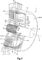
- the Figures 1 to 4 represent a torque transmission device 1, in particular for a motor vehicle, according to one embodiment of the invention.
- It comprises a cover 2 of axis X, comprising an annular radial portion 3 whose radially outer periphery is extended by a cylindrical portion 4 extending forwardly.
- the front face of the radial portion 3 comprises a bearing zone 5 projecting and annular shape, of rounded section.
- the bearing zone 5 is for example formed by deformation of the cover material, for example by stamping.
- the cylindrical portion 4 comprises a succession of grooves 6 extending axially and distributed over the entire circumference.
- the radial portion is intended to be coupled in rotation directly or indirectly to a crankshaft of an internal combustion engine 7 ( figures 3 and 4 ).
- the device 1 further comprises clutch means comprising a central hub 8 whose radially inner periphery is grooved and cooperates with splines 9 of an input shaft 10 of a gearbox 10a.
- the central hub 8 and the input shaft 10 of the gearbox are thus coupled in rotation.
- the clutch means further comprise friction discs 11 interposed between annular plates 12.
- the clutch means comprise four plates 12 and three friction discs 11, the plates 12 and the friction discs 11 being mounted alternately.
- the outer peripheries of the trays 12 comprise teeth 13 adapted to engage in the grooves 6 of the cover 2, so as to couple in rotation the trays 12 and the cover 2 while allowing the axial displacement of the trays 12.
- the internal peripheries of the friction discs 11 comprise teeth 14 adapted to engage with splines 15 of the radially outer periphery of the central hub 8 so as to couple in rotation the friction discs 11 and the central hub 8 while allowing a axial displacement of the friction discs 11 relative to the hub 8.
- the rear plate 12 is able to bear against the radial portion 3 of the cover 2, in particular on the projecting annular zone 5 of the cover 2.
- a support member 16 is mounted forward of the plate 12 before, the support member 16 having a bearing portion 17 annular projecting forwardly.
- the clutch means further comprise a diaphragm 18 whose outer periphery is adapted to bear against a conical washer 19 located directly in front of the diaphragm 18, said washer 19 itself bearing on an elastic ring or circlip 20, mounted in front of the conical washer 19, in a groove in the cylindrical portion 4 of the cover 2.
- the conical bearing washer 19 is fixed axially relative to the cover 2.
- the bearing zone 17 of the member 16 is able to bear on the diaphragm 18, in an area located radially inside the conical bearing washer 19.
- the device 1 further comprises actuating means comprising a clutch abutment 21.
- Said clutch abutment 21 comprises a portion 22 fixed relative to the cover 2, an actuating member 23 movable relative to the fixed portion 22 in the axial direction.
- the actuating member 23 has an annular shape and may be formed by a piston housed in a chamber of the fixed part 22, for example.
- a connecting member 24 is mounted inside the cylindrical portion 4 of the cover 2.
- the connecting member 24 is annular, extends radially and has teeth 25 at its radially outer periphery and is coupled to a first portion. 26 of a freewheel mechanism.
- the teeth 25 of the radially outer periphery cooperate with the splines 6 of the cylindrical portion 4 of the cover 2 so as to couple in rotation the connecting member 24 and the cover 2.
- the connecting member 24 is held axially between two members elastic or circlip 20 disposed respectively at the front and at the rear, mounted in grooves of the cover 2.
- An annular transmission member 28 is mounted around the input shaft 10 of the gearbox.
- the transmission member 28 extends radially, has teeth 29 at its radially inner periphery and is coupled to a second portion 30 of the freewheel mechanism.
- the teeth 29 of the radially inner periphery cooperate with the splines 9 of the input shaft 10 of the gearbox.
- Said freewheel mechanism is able to transmit torque from the first part 29 to the second part 30, in a first direction of rotation of the first part 29 with respect to the second part 30, said mechanism being able to decouple in rotation the first part 29 and the second part 30 in a direction of rotation, opposite to the first direction of rotation.
- the hub 8 and the transmission member 28 are held axially in position on the axis 10, by means of circlip-type elastic rings 8a, 28a mounted in grooves of the shaft 10.
- the transmission member 28 comprises at least one orifice 31, for example three orifices regularly distributed around the axis X.
- Each orifice 31 is traversed by a pusher member 32 able to slide axially through said orifice 31.
- Each pusher member 32 is mounted axially between two bearings 33, 34 formed here by rolling stops, more particularly needle stops.
- a first bearing 33 is interposed axially between the radially inner periphery of the diaphragm 18 and the pusher member 32.
- a second bearing 34 is interposed axially between the pusher member 32 and the actuating member 23.
- a washer 35 may be interposed axially between each bearing 33, 34 and the pusher member 32.
- the pusher member 32 is moved axially with the actuating member of the clutch abutment 21.
- the pusher member 32 is also integral in rotation with the transmission member.
- the cover 2 is intended to be coupled in rotation directly or indirectly with the crankshaft of the internal combustion engine 7 of a motor vehicle, schematically illustrated in FIGS. figures 3 and 4 .
- a rotor 37 of an electric machine is rotatably coupled, via a support 38 for example, to the input shaft 10 of the gearbox 10a. Such coupling can be ensured by any means.
- the electric machine is for example a reversible rotary electric machine of the alternator-starter type or of the motor-generator type.
- An additional cover 39 may be provided, said additional cover 39 housing the cover 2 and the clutch stop 21.
- additional cover 39 comprises here a radial portion 40 forward, annular and surrounding the input shaft 10, whose radially outer periphery is extended rearwardly by an axial portion 41.
- the actuating member 23 and the diaphragm 18 can be moved between a plurality of axial positions, as shown respectively in FIGS. figures 3 and 4 .
- the figure 3 illustrates a first mode of operation and / or a second mode of operation.
- the actuating member 23 in a first mode of operation, is moved forwards, that is to say to the right in said figure.
- the actuating member 23 does not push the diaphragm 18 towards its engaged position.
- the diaphragm 18 is recalled, because of its elasticity, to its disengaged position.
- the shaft 10, the transmission member 28 and the second portion 30 of the freewheel mechanism pivot in the second direction of rotation (so-called retro direction) relative to the cover 2, to the connecting member 24 and the first part 26 of the freewheel mechanism so that said freewheel mechanism transmits no torque between its first and second parts 26, 30.
- crankshaft 7 and the cover 2 are decoupled from the input shaft 10 of the gearbox 10a and the rotor 37 of the electric machine.
- the input shaft 10 of the gearbox 10a and the rotor 37 of the electric machine remain coupled in rotation.
- the electric machine can then be adapted to drive the input shaft 10 of the gearbox 10a, and thus the vehicle, at least for a short distance.
- actuating member 23 In a second mode of operation also illustrated by the figure 3 , the actuating member 23 remains moved forward, that is to say to the right in said figure. Thus, in the second mode of operation, the actuating member 23 does not push the diaphragm 18 towards its engaged position. In other words, the diaphragm 18 is recalled, because of its elasticity, to its disengaged position.
- the shaft 10, the transmission member 28 and the second portion 30 of the freewheel mechanism pivot in the first direction of rotation (direct direction) relative to the cover 2, to the connecting member 24 and the first part 26 of the freewheel mechanism so that said freewheel mechanism makes it possible to transmit the torque between its first and second parts 26, 30.
- crankshaft of the internal combustion engine 7 is then rotatably coupled to the input shaft 10 of the gearbox 10a, via the cover 2, the connecting member 24 and the transmission member. 28.
- the torque passage is thus made directly between the crankshaft and the input shaft 10 of the gearbox 10a, that is to say without the use of clutch means.
- Such an operating mode can in particular be used to drive the input shaft 10 of the gearbox 10a with the aid of the internal combustion engine 7, when the latter is started.
- the electric machine can operate in generator or alternator mode, in order to recharge a battery of the vehicle and / or to power the organs or equipment consuming energy when the internal combustion engine 7 is running.
- the electric machine may further be configured to recover energy when braking the vehicle.
- the electric machine is able to provide a surplus of power to prevent the internal combustion engine 7 stalls (boost function in English).
- the figure 4 illustrates a third mode of operation in which the actuating member 23 is moved rearward, that is to say to the left in said figure.
- the shaft 10, the transmission member 28 and the second portion 30 of the freewheel mechanism pivot in the second direction of rotation (so-called retro direction) relative to the cover 2, to the connecting member 24 and the first part 26 of the freewheel mechanism so that said freewheel mechanism transmits no torque between its first and second parts 26, 30.
- the pusher member 32 is moved backwards by the actuating member 23 so that the bearing 33 actuates the diaphragm 18 so as to move it towards its engaged position in which it brings the axially the plates 12 of the radial portion 3 of the cover 2.
- the friction discs 11 are sandwiched between the plates 12 and the cover 2 is coupled in rotation to the input shaft 10 of the gearbox 10a by through the trays 12, friction discs 11 and the central hub 8.
- the rotor 37 of the electric machine is rotatably coupled to the crankshaft of the internal combustion engine 7, via the aforementioned clutch means.
- Such a mode of operation can in particular be used in the case where it is desired to restart the internal combustion engine 7 with the help of the electric machine which then operates in engine mode (Stop and Go function, in English).
- the stopping of the internal combustion engine 7 may in particular be controlled during a short stop of the vehicle, for example in the case of a red light or in plugs.
- the torque generated by the rotor 37 of the electric machine is transmitted to the input shaft 10 of the gearbox 10a via the support 38, then to the crankshaft 7 via the cover 2 and aforementioned clutch means.
- the invention thus proposes a reliable torque transmission device, which is not very bulky axially and radially, is not very complex and inexpensive, compared with the prior art.
Landscapes
- Engineering & Computer Science (AREA)
- General Engineering & Computer Science (AREA)
- Mechanical Engineering (AREA)
- Mechanical Operated Clutches (AREA)
- Hybrid Electric Vehicles (AREA)
Claims (11)
- Vorrichtung (1) zur Drehmomentübertragung, insbesondere für ein Kraftfahrzeug, welche aufweist:- Drehmomenteingangsmittel (2), die dazu bestimmt sind, mit einer Kurbelwelle einer Brennkraftmaschine (7) drehgekoppelt zu werden,- Drehmomentausgangsmittel (8), die dazu bestimmt sind, mit einer Eingangswelle (10) eines Getriebes (10a) und mit einem Rotor (37) einer elektrischen Maschine drehgekoppelt zu werden, wobei die Drehmomenteingangsmittel (2) dafür ausgelegt sind, bezüglich der Drehmomentausgangsmittel um eine Achse (X) zu schwenken,- Kupplungsmittel, die eine Wechselfolge von Platten (12) und von Reibscheiben (11) aufweisen, sowie eine Membran (18), die dafür ausgelegt ist, zwischen einer eingekuppelten Position, in der sie bestrebt ist, die Reibscheiben (11) zwischen den Platten (12) festzuklemmen, und einer ausgekuppelten Position, in der sie die Reibscheiben (11) freigibt, umzuschalten,- ein Kupplungsausrücklager (21), das ein Betätigungsorgan (23) aufweist, das zwischen einer ersten axialen Position und einer zweiten axialen Position beweglich ist, wobei das Betätigungsorgan (23) über wenigstens ein Schuborgan (32) auf der Membran (18) abgestützt ist, wobei das Schuborgan (32) axial zwischen zwei Lagern (33, 34) angebracht ist,wobei die Vorrichtung einen Freilaufmechanismus aufweist, der einen ersten Teil (26) und einen zweiten Teil (30) aufweist, wobei der Mechanismus dafür ausgelegt ist, in einer ersten Drehrichtung des ersten Teils (26) bezüglich des zweiten Teils (30) Drehmoment vom ersten Teil (26) auf den zweiten Teil (30) zu übertragen, wobei der Mechanismus dafür ausgelegt ist, in einer zur ersten Drehrichtung entgegengesetzten Drehrichtung den ersten Teil (26) und den zweiten Teil (30) hinsichtlich der Drehung zu entkoppeln.
- Vorrichtung (1) nach Anspruch 1, dadurch gekennzeichnet, dass:- in der ersten Position des Betätigungsorgans (23) und während der Drehung des ersten Teils (26) des Freilaufmechanismus bezüglich des zweiten Teils (30) in der zweiten Drehrichtung die Drehmomenteingangsmittel (2) und die Drehmomentausgangsmittel ausschließlich über einen ersten Drehmomentübertragungsweg, der Kupplungsmittel (11, 12, 18) aufweist, drehgekoppelt sind, wobei die Kupplungsmittel eine Wechselfolge von Platten und von Reibscheiben aufweisen,- in der zweiten Position des Betätigungsorgans (23) und während der Drehung des ersten Teils (26) des Freilaufmechanismus bezüglich des zweiten Teils (30) in der ersten Drehrichtung die Drehmomenteingangsmittel (2) und die Drehmomentausgangsmittel ausschließlich über einen zweiten Drehmomentübertragungsweg, der den Freilaufmechanismus umfasst, drehgekoppelt sind.
- Vorrichtung (1) nach Anspruch 2, dadurch gekennzeichnet, dass das bewegliche Betätigungsorgan (23) und der Freilaufmechanismus (26, 30) so gestaltet sind, dass in der zweiten Position des Betätigungsorgans (23) und während der Drehung des ersten Teils (26) des Freilaufmechanismus bezüglich des zweiten Teils (30) in der zweiten Drehrichtung die Drehmomenteingangsmittel (2) und die Drehmomentausgangsmittel (8) drehentkoppelt sind.
- Vorrichtung nach einem der Ansprüche 1 bis 3, dadurch gekennzeichnet, dass sie ein Übertragungsorgan (28) aufweist, das einen ersten Kopplungsbereich (29), der dazu bestimmt ist, mit der Eingangswelle (10) des Getriebes (10a) drehgekoppelt zu werden, und einen zweiten Kopplungsbereich (30), der mit dem zweiten Teil (30) des Freilaufmechanismus gekoppelt ist, umfasst, wobei der erste Teil (26) des Freilaufmechanismus mit den Drehmomenteingangsmitteln (2) gekoppelt ist.
- Vorrichtung (1) nach Anspruch 4, dadurch gekennzeichnet, dass sich der erste Kopplungsbereich (29) radial innerhalb des Übertragungsorgans (28) befindet, während sich der zweite Kopplungsbereich (30) radial außerhalb des Übertragungsorgans (28) befindet.
- Vorrichtung (1) nach einem der Ansprüche 1 bis 5, dadurch gekennzeichnet, dass, wenn die Reibscheiben (11) bzw. die Platten (12) mit einer Nabe (8) drehgekoppelt sind, die zu den Drehmomentausgangsmitteln gehört, während die Platten (12) bzw. die Reibscheiben (11) mit den Drehmomenteingangsmitteln (2) gekoppelt sind, die Platte (12) derart axial aneinander angenähert werden, dass sie die Reibscheiben (11) festklemmen, wenn das Betätigungsorgan (23) in seine erste Position bewegt wird.
- Vorrichtung (1) nach einem der Ansprüche 1 bis 6, dadurch gekennzeichnet, dass die Membran (18) ringförmig ist, wobei das Betätigungsorgan (23) in der ersten axialen Position am radial inneren Umfang der Membran (18) zur Anlage kommt, wobei die Membran (18) schwenkbar um einen radial äußeren ersten Anlagebereich (19) gelagert ist, wobei die Membran (18) in einem zweiten Anlagebereich (17), der sich radial innerhalb des ersten Anlagebereichs (19) befindet, direkt oder indirekt an einer der Platten (12) zur Anlage kommt.
- Vorrichtung (1) nach einem der Ansprüche 1 bis 7, dadurch gekennzeichnet, dass die Drehmomenteingangsmittel eine Abdeckung (2) aufweisen, die wenigstens teilweise die Kupplungsmittel (11, 12, 18), das Betätigungsorgan (23), das Übertragungsorgan (28), den Freilaufmechanismus (26, 30) und die Nabe (8) aufnimmt.
- Vorrichtung (1) nach Anspruch 4 oder 5 und nach Anspruch 8, dadurch gekennzeichnet, dass die Drehmomenteingangsmittel ein Verbindungsorgan (24) aufweisen, das mit der Abdeckung (2) drehgekoppelt ist, wobei der zweite Kopplungsbereich (30) des Übertragungsorgans (28) und das Verbindungsorgan (24) über den Freilaufmechanismus (26, 30) drehgekoppelt sind.
- Vorrichtung (1) nach einem der Ansprüche 4 bis 9, dadurch gekennzeichnet, dass das Schuborgan (32) eine Öffnung (31) des Übertragungsorgans (28) axial durchquert, wobei das Schuborgan (32) dafür ausgelegt ist, bezüglich des Übertragungsorgans (28) axial verschoben zu werden.
- Hybridantriebssystem, welches umfasst:- eine Brennkraftmaschine (7), die eine Kurbelwelle aufweist, die dafür ausgelegt ist, um eine Achse (X) drehend angetrieben zu werden,- eine elektrische Maschine, die einen Stator und einen Rotor (37), der dafür ausgelegt ist, bezüglich des Stators um die Achse (X) drehend angetrieben zu werden, aufweist,- ein Getriebe (10a), das eine Eingangswelle (10) aufweist,- eine Vorrichtung (1) zur Drehmomentübertragung nach einem der Ansprüche 1 bis 10, wobei der Rotor (37), die Eingangswelle (10) des Getriebes (10a) und die Drehmomentausgangsmittel drehgekoppelt sind,- wobei die Drehmomenteingangsmittel (2) und die Kurbelwelle drehgekoppelt sind.
Applications Claiming Priority (1)
| Application Number | Priority Date | Filing Date | Title |
|---|---|---|---|
| FR1662221A FR3060083B1 (fr) | 2016-12-09 | 2016-12-09 | Dispositif de transmission de couple, notamment pour vehicule automobile |
Publications (2)
| Publication Number | Publication Date |
|---|---|
| EP3333440A1 EP3333440A1 (de) | 2018-06-13 |
| EP3333440B1 true EP3333440B1 (de) | 2019-03-13 |
Family
ID=58010038
Family Applications (1)
| Application Number | Title | Priority Date | Filing Date |
|---|---|---|---|
| EP17204600.5A Not-in-force EP3333440B1 (de) | 2016-12-09 | 2017-11-30 | Drehmomentübertragungsvorrichtung, insbesondere für kraftfahrzeug |
Country Status (2)
| Country | Link |
|---|---|
| EP (1) | EP3333440B1 (de) |
| FR (1) | FR3060083B1 (de) |
Families Citing this family (1)
| Publication number | Priority date | Publication date | Assignee | Title |
|---|---|---|---|---|
| FR3086714B1 (fr) * | 2018-10-01 | 2021-01-22 | Valeo Embrayages | Dispositif de transmission pour vehicule hybride |
Family Cites Families (3)
| Publication number | Priority date | Publication date | Assignee | Title |
|---|---|---|---|---|
| DE102007061895B4 (de) * | 2007-12-20 | 2018-05-09 | Dr. Ing. H.C. F. Porsche Aktiengesellschaft | Hybridfahrzeug und Verfahren zum Starten des Verbrennungsmotors eines Hybridfahrzeuges |
| WO2012149924A1 (de) * | 2011-05-05 | 2012-11-08 | Schaeffler Technologies AG & Co. KG | Hybridmodul für einen triebstrang eines fahrzeuges |
| CN107429759B (zh) * | 2015-04-17 | 2019-06-14 | 舍弗勒技术股份两合公司 | 离合器系统 |
-
2016
- 2016-12-09 FR FR1662221A patent/FR3060083B1/fr not_active Expired - Fee Related
-
2017
- 2017-11-30 EP EP17204600.5A patent/EP3333440B1/de not_active Not-in-force
Non-Patent Citations (1)
| Title |
|---|
| None * |
Also Published As
| Publication number | Publication date |
|---|---|
| FR3060083A1 (fr) | 2018-06-15 |
| EP3333440A1 (de) | 2018-06-13 |
| FR3060083B1 (fr) | 2019-11-01 |
Similar Documents
| Publication | Publication Date | Title |
|---|---|---|
| EP3254878B1 (de) | Drehmomentübertragungsvorrichtung, insbesondere für kraftfahrzeug | |
| EP2990678B1 (de) | Kupplungsvorrichtung für kraftfahrzeug | |
| EP4047235B1 (de) | Modul für ein system zur synchronisation und zum antrieb einer zwischenwelle eines getriebes | |
| WO2003031215A1 (fr) | Ensemble de transmission comprenant deux embrayages et une machine electrique, notamment pour vehicule automobile | |
| EP3580468B1 (de) | Lösbarer doppelkupplungsmechanismus | |
| EP4011670A1 (de) | Hybride unterantriebseinheit eines fahrzeugs | |
| FR3060083B1 (fr) | Dispositif de transmission de couple, notamment pour vehicule automobile | |
| FR3079455A1 (fr) | Dispositif de transmission pour vehicule hybride | |
| WO2018096114A1 (fr) | Assemblage radial d'un mecanisme d'embrayage sur une transmission | |
| EP4380810B1 (de) | Antriebsstrang für ein hybrid-antriebs- oder zugkraftfahrzeug mit einem mechanismus zum blockieren des verbrennungsmotors | |
| WO2019211244A1 (fr) | Dispositif de transmission pour vehicule automobile | |
| FR2862025A1 (fr) | Element de transmission a double embrayage pour chaine de traction hybride de vehicule automobile equipe d'un tel element | |
| FR3078378A1 (fr) | Dispositif de transmission pour vehicule | |
| WO2018037179A1 (fr) | Dispositif de transmission de couple | |
| FR3060082A1 (fr) | Dispositif de transmission de couple, notamment pour vehicule automobile | |
| FR3081949A1 (fr) | Dispositif de transmission pour vehicule hybride | |
| WO2019166510A1 (fr) | Dispositif de transmission pour vehicule hybride | |
| WO2019166516A1 (fr) | Dispositif de transmission pour vehicule hybride | |
| FR3150559A1 (fr) | MODULE MOTORISE ET ensemble DE TRANSMISSION hybride d’un véhicule | |
| WO2019092385A1 (fr) | Dispositif et systeme de transmission de couple | |
| FR2831861A1 (fr) | Systeme de propulsion pour un vehicule automobile | |
| WO2014049240A1 (fr) | Dispositif pour véhicule hybride avec un moyeu de support d'un rotor réalisé en tôle et portant un plateau de réaction d'un embrayage | |
| EP4279308A1 (de) | Hybridantriebsbaugruppe für ein fahrzeug | |
| FR3096101A1 (fr) | Module hybride pour véhicule automobile | |
| FR3117182A1 (fr) | BOITE DE VITESSES d’entraînement d’un véhicule |
Legal Events
| Date | Code | Title | Description |
|---|---|---|---|
| PUAI | Public reference made under article 153(3) epc to a published international application that has entered the european phase |
Free format text: ORIGINAL CODE: 0009012 |
|
| STAA | Information on the status of an ep patent application or granted ep patent |
Free format text: STATUS: REQUEST FOR EXAMINATION WAS MADE |
|
| 17P | Request for examination filed |
Effective date: 20171130 |
|
| AK | Designated contracting states |
Kind code of ref document: A1 Designated state(s): AL AT BE BG CH CY CZ DE DK EE ES FI FR GB GR HR HU IE IS IT LI LT LU LV MC MK MT NL NO PL PT RO RS SE SI SK SM TR |
|
| AX | Request for extension of the european patent |
Extension state: BA ME |
|
| GRAP | Despatch of communication of intention to grant a patent |
Free format text: ORIGINAL CODE: EPIDOSNIGR1 |
|
| STAA | Information on the status of an ep patent application or granted ep patent |
Free format text: STATUS: GRANT OF PATENT IS INTENDED |
|
| RIC1 | Information provided on ipc code assigned before grant |
Ipc: F16D 47/04 20060101ALI20181026BHEP Ipc: B60K 6/48 20071001ALN20181026BHEP Ipc: F16D 41/04 20060101AFI20181026BHEP |
|
| INTG | Intention to grant announced |
Effective date: 20181120 |
|
| GRAS | Grant fee paid |
Free format text: ORIGINAL CODE: EPIDOSNIGR3 |
|
| GRAA | (expected) grant |
Free format text: ORIGINAL CODE: 0009210 |
|
| STAA | Information on the status of an ep patent application or granted ep patent |
Free format text: STATUS: THE PATENT HAS BEEN GRANTED |
|
| RIC1 | Information provided on ipc code assigned before grant |
Ipc: F16D 41/04 20060101AFI20181026BHEP Ipc: B60K 6/48 20071001ALN20181026BHEP Ipc: F16D 47/04 20060101ALI20181026BHEP |
|
| AK | Designated contracting states |
Kind code of ref document: B1 Designated state(s): AL AT BE BG CH CY CZ DE DK EE ES FI FR GB GR HR HU IE IS IT LI LT LU LV MC MK MT NL NO PL PT RO RS SE SI SK SM TR |
|
| REG | Reference to a national code |
Ref country code: GB Ref legal event code: FG4D Free format text: NOT ENGLISH |
|
| REG | Reference to a national code |
Ref country code: CH Ref legal event code: EP Ref country code: AT Ref legal event code: REF Ref document number: 1108116 Country of ref document: AT Kind code of ref document: T Effective date: 20190315 |
|
| REG | Reference to a national code |
Ref country code: IE Ref legal event code: FG4D Free format text: LANGUAGE OF EP DOCUMENT: FRENCH |
|
| REG | Reference to a national code |
Ref country code: DE Ref legal event code: R096 Ref document number: 602017002715 Country of ref document: DE |
|
| REG | Reference to a national code |
Ref country code: NL Ref legal event code: MP Effective date: 20190313 |
|
| REG | Reference to a national code |
Ref country code: LT Ref legal event code: MG4D |
|
| PG25 | Lapsed in a contracting state [announced via postgrant information from national office to epo] |
Ref country code: LT Free format text: LAPSE BECAUSE OF FAILURE TO SUBMIT A TRANSLATION OF THE DESCRIPTION OR TO PAY THE FEE WITHIN THE PRESCRIBED TIME-LIMIT Effective date: 20190313 Ref country code: SE Free format text: LAPSE BECAUSE OF FAILURE TO SUBMIT A TRANSLATION OF THE DESCRIPTION OR TO PAY THE FEE WITHIN THE PRESCRIBED TIME-LIMIT Effective date: 20190313 Ref country code: FI Free format text: LAPSE BECAUSE OF FAILURE TO SUBMIT A TRANSLATION OF THE DESCRIPTION OR TO PAY THE FEE WITHIN THE PRESCRIBED TIME-LIMIT Effective date: 20190313 Ref country code: NO Free format text: LAPSE BECAUSE OF FAILURE TO SUBMIT A TRANSLATION OF THE DESCRIPTION OR TO PAY THE FEE WITHIN THE PRESCRIBED TIME-LIMIT Effective date: 20190613 |
|
| PG25 | Lapsed in a contracting state [announced via postgrant information from national office to epo] |
Ref country code: LV Free format text: LAPSE BECAUSE OF FAILURE TO SUBMIT A TRANSLATION OF THE DESCRIPTION OR TO PAY THE FEE WITHIN THE PRESCRIBED TIME-LIMIT Effective date: 20190313 Ref country code: BG Free format text: LAPSE BECAUSE OF FAILURE TO SUBMIT A TRANSLATION OF THE DESCRIPTION OR TO PAY THE FEE WITHIN THE PRESCRIBED TIME-LIMIT Effective date: 20190613 Ref country code: RS Free format text: LAPSE BECAUSE OF FAILURE TO SUBMIT A TRANSLATION OF THE DESCRIPTION OR TO PAY THE FEE WITHIN THE PRESCRIBED TIME-LIMIT Effective date: 20190313 Ref country code: GR Free format text: LAPSE BECAUSE OF FAILURE TO SUBMIT A TRANSLATION OF THE DESCRIPTION OR TO PAY THE FEE WITHIN THE PRESCRIBED TIME-LIMIT Effective date: 20190614 Ref country code: HR Free format text: LAPSE BECAUSE OF FAILURE TO SUBMIT A TRANSLATION OF THE DESCRIPTION OR TO PAY THE FEE WITHIN THE PRESCRIBED TIME-LIMIT Effective date: 20190313 Ref country code: NL Free format text: LAPSE BECAUSE OF FAILURE TO SUBMIT A TRANSLATION OF THE DESCRIPTION OR TO PAY THE FEE WITHIN THE PRESCRIBED TIME-LIMIT Effective date: 20190313 |
|
| REG | Reference to a national code |
Ref country code: AT Ref legal event code: MK05 Ref document number: 1108116 Country of ref document: AT Kind code of ref document: T Effective date: 20190313 |
|
| PG25 | Lapsed in a contracting state [announced via postgrant information from national office to epo] |
Ref country code: AL Free format text: LAPSE BECAUSE OF FAILURE TO SUBMIT A TRANSLATION OF THE DESCRIPTION OR TO PAY THE FEE WITHIN THE PRESCRIBED TIME-LIMIT Effective date: 20190313 Ref country code: PT Free format text: LAPSE BECAUSE OF FAILURE TO SUBMIT A TRANSLATION OF THE DESCRIPTION OR TO PAY THE FEE WITHIN THE PRESCRIBED TIME-LIMIT Effective date: 20190713 Ref country code: ES Free format text: LAPSE BECAUSE OF FAILURE TO SUBMIT A TRANSLATION OF THE DESCRIPTION OR TO PAY THE FEE WITHIN THE PRESCRIBED TIME-LIMIT Effective date: 20190313 Ref country code: SK Free format text: LAPSE BECAUSE OF FAILURE TO SUBMIT A TRANSLATION OF THE DESCRIPTION OR TO PAY THE FEE WITHIN THE PRESCRIBED TIME-LIMIT Effective date: 20190313 Ref country code: EE Free format text: LAPSE BECAUSE OF FAILURE TO SUBMIT A TRANSLATION OF THE DESCRIPTION OR TO PAY THE FEE WITHIN THE PRESCRIBED TIME-LIMIT Effective date: 20190313 Ref country code: IT Free format text: LAPSE BECAUSE OF FAILURE TO SUBMIT A TRANSLATION OF THE DESCRIPTION OR TO PAY THE FEE WITHIN THE PRESCRIBED TIME-LIMIT Effective date: 20190313 Ref country code: RO Free format text: LAPSE BECAUSE OF FAILURE TO SUBMIT A TRANSLATION OF THE DESCRIPTION OR TO PAY THE FEE WITHIN THE PRESCRIBED TIME-LIMIT Effective date: 20190313 Ref country code: CZ Free format text: LAPSE BECAUSE OF FAILURE TO SUBMIT A TRANSLATION OF THE DESCRIPTION OR TO PAY THE FEE WITHIN THE PRESCRIBED TIME-LIMIT Effective date: 20190313 |
|
| PG25 | Lapsed in a contracting state [announced via postgrant information from national office to epo] |
Ref country code: SM Free format text: LAPSE BECAUSE OF FAILURE TO SUBMIT A TRANSLATION OF THE DESCRIPTION OR TO PAY THE FEE WITHIN THE PRESCRIBED TIME-LIMIT Effective date: 20190313 Ref country code: PL Free format text: LAPSE BECAUSE OF FAILURE TO SUBMIT A TRANSLATION OF THE DESCRIPTION OR TO PAY THE FEE WITHIN THE PRESCRIBED TIME-LIMIT Effective date: 20190313 |
|
| REG | Reference to a national code |
Ref country code: DE Ref legal event code: R097 Ref document number: 602017002715 Country of ref document: DE |
|
| PG25 | Lapsed in a contracting state [announced via postgrant information from national office to epo] |
Ref country code: IS Free format text: LAPSE BECAUSE OF FAILURE TO SUBMIT A TRANSLATION OF THE DESCRIPTION OR TO PAY THE FEE WITHIN THE PRESCRIBED TIME-LIMIT Effective date: 20190713 Ref country code: AT Free format text: LAPSE BECAUSE OF FAILURE TO SUBMIT A TRANSLATION OF THE DESCRIPTION OR TO PAY THE FEE WITHIN THE PRESCRIBED TIME-LIMIT Effective date: 20190313 |
|
| PLBE | No opposition filed within time limit |
Free format text: ORIGINAL CODE: 0009261 |
|
| STAA | Information on the status of an ep patent application or granted ep patent |
Free format text: STATUS: NO OPPOSITION FILED WITHIN TIME LIMIT |
|
| PG25 | Lapsed in a contracting state [announced via postgrant information from national office to epo] |
Ref country code: DK Free format text: LAPSE BECAUSE OF FAILURE TO SUBMIT A TRANSLATION OF THE DESCRIPTION OR TO PAY THE FEE WITHIN THE PRESCRIBED TIME-LIMIT Effective date: 20190313 |
|
| 26N | No opposition filed |
Effective date: 20191216 |
|
| PG25 | Lapsed in a contracting state [announced via postgrant information from national office to epo] |
Ref country code: TR Free format text: LAPSE BECAUSE OF FAILURE TO SUBMIT A TRANSLATION OF THE DESCRIPTION OR TO PAY THE FEE WITHIN THE PRESCRIBED TIME-LIMIT Effective date: 20190313 |
|
| PG25 | Lapsed in a contracting state [announced via postgrant information from national office to epo] |
Ref country code: MC Free format text: LAPSE BECAUSE OF FAILURE TO SUBMIT A TRANSLATION OF THE DESCRIPTION OR TO PAY THE FEE WITHIN THE PRESCRIBED TIME-LIMIT Effective date: 20190313 Ref country code: LU Free format text: LAPSE BECAUSE OF NON-PAYMENT OF DUE FEES Effective date: 20191130 |
|
| REG | Reference to a national code |
Ref country code: BE Ref legal event code: MM Effective date: 20191130 |
|
| PG25 | Lapsed in a contracting state [announced via postgrant information from national office to epo] |
Ref country code: IE Free format text: LAPSE BECAUSE OF NON-PAYMENT OF DUE FEES Effective date: 20191130 |
|
| PG25 | Lapsed in a contracting state [announced via postgrant information from national office to epo] |
Ref country code: BE Free format text: LAPSE BECAUSE OF NON-PAYMENT OF DUE FEES Effective date: 20191130 |
|
| PG25 | Lapsed in a contracting state [announced via postgrant information from national office to epo] |
Ref country code: CY Free format text: LAPSE BECAUSE OF FAILURE TO SUBMIT A TRANSLATION OF THE DESCRIPTION OR TO PAY THE FEE WITHIN THE PRESCRIBED TIME-LIMIT Effective date: 20190313 |
|
| REG | Reference to a national code |
Ref country code: CH Ref legal event code: PL |
|
| PG25 | Lapsed in a contracting state [announced via postgrant information from national office to epo] |
Ref country code: HU Free format text: LAPSE BECAUSE OF FAILURE TO SUBMIT A TRANSLATION OF THE DESCRIPTION OR TO PAY THE FEE WITHIN THE PRESCRIBED TIME-LIMIT; INVALID AB INITIO Effective date: 20171130 Ref country code: MT Free format text: LAPSE BECAUSE OF FAILURE TO SUBMIT A TRANSLATION OF THE DESCRIPTION OR TO PAY THE FEE WITHIN THE PRESCRIBED TIME-LIMIT Effective date: 20190313 |
|
| PG25 | Lapsed in a contracting state [announced via postgrant information from national office to epo] |
Ref country code: LI Free format text: LAPSE BECAUSE OF NON-PAYMENT OF DUE FEES Effective date: 20201130 Ref country code: CH Free format text: LAPSE BECAUSE OF NON-PAYMENT OF DUE FEES Effective date: 20201130 |
|
| PG25 | Lapsed in a contracting state [announced via postgrant information from national office to epo] |
Ref country code: SI Free format text: LAPSE BECAUSE OF FAILURE TO SUBMIT A TRANSLATION OF THE DESCRIPTION OR TO PAY THE FEE WITHIN THE PRESCRIBED TIME-LIMIT Effective date: 20190313 |
|
| PG25 | Lapsed in a contracting state [announced via postgrant information from national office to epo] |
Ref country code: MK Free format text: LAPSE BECAUSE OF FAILURE TO SUBMIT A TRANSLATION OF THE DESCRIPTION OR TO PAY THE FEE WITHIN THE PRESCRIBED TIME-LIMIT Effective date: 20190313 |
|
| GBPC | Gb: european patent ceased through non-payment of renewal fee |
Effective date: 20211130 |
|
| PG25 | Lapsed in a contracting state [announced via postgrant information from national office to epo] |
Ref country code: GB Free format text: LAPSE BECAUSE OF NON-PAYMENT OF DUE FEES Effective date: 20211130 |
|
| PGFP | Annual fee paid to national office [announced via postgrant information from national office to epo] |
Ref country code: FR Payment date: 20221122 Year of fee payment: 6 Ref country code: DE Payment date: 20221114 Year of fee payment: 6 |
|
| P01 | Opt-out of the competence of the unified patent court (upc) registered |
Effective date: 20230528 |
|
| REG | Reference to a national code |
Ref country code: DE Ref legal event code: R119 Ref document number: 602017002715 Country of ref document: DE |
|
| PG25 | Lapsed in a contracting state [announced via postgrant information from national office to epo] |
Ref country code: DE Free format text: LAPSE BECAUSE OF NON-PAYMENT OF DUE FEES Effective date: 20240601 |
|
| PG25 | Lapsed in a contracting state [announced via postgrant information from national office to epo] |
Ref country code: FR Free format text: LAPSE BECAUSE OF NON-PAYMENT OF DUE FEES Effective date: 20231130 |
|
| PG25 | Lapsed in a contracting state [announced via postgrant information from national office to epo] |
Ref country code: FR Free format text: LAPSE BECAUSE OF NON-PAYMENT OF DUE FEES Effective date: 20231130 Ref country code: DE Free format text: LAPSE BECAUSE OF NON-PAYMENT OF DUE FEES Effective date: 20240601 |