EP3333435B1 - Landebahnbeleuchtung - Google Patents
Landebahnbeleuchtung Download PDFInfo
- Publication number
- EP3333435B1 EP3333435B1 EP17204765.6A EP17204765A EP3333435B1 EP 3333435 B1 EP3333435 B1 EP 3333435B1 EP 17204765 A EP17204765 A EP 17204765A EP 3333435 B1 EP3333435 B1 EP 3333435B1
- Authority
- EP
- European Patent Office
- Prior art keywords
- top portion
- slots
- pin
- base portion
- lateral protrusions
- Prior art date
- Legal status (The legal status is an assumption and is not a legal conclusion. Google has not performed a legal analysis and makes no representation as to the accuracy of the status listed.)
- Active
Links
Images


Classifications
-
- B—PERFORMING OPERATIONS; TRANSPORTING
- B64—AIRCRAFT; AVIATION; COSMONAUTICS
- B64F—GROUND OR AIRCRAFT-CARRIER-DECK INSTALLATIONS SPECIALLY ADAPTED FOR USE IN CONNECTION WITH AIRCRAFT; DESIGNING, MANUFACTURING, ASSEMBLING, CLEANING, MAINTAINING OR REPAIRING AIRCRAFT, NOT OTHERWISE PROVIDED FOR; HANDLING, TRANSPORTING, TESTING OR INSPECTING AIRCRAFT COMPONENTS, NOT OTHERWISE PROVIDED FOR
- B64F1/00—Ground or aircraft-carrier-deck installations
- B64F1/18—Visual or acoustic landing aids
- B64F1/20—Arrangement of optical beacons
- B64F1/205—Arrangement of optical beacons arranged underground, e.g. underground runway lighting units
-
- F—MECHANICAL ENGINEERING; LIGHTING; HEATING; WEAPONS; BLASTING
- F21—LIGHTING
- F21S—NON-PORTABLE LIGHTING DEVICES; SYSTEMS THEREOF; VEHICLE LIGHTING DEVICES SPECIALLY ADAPTED FOR VEHICLE EXTERIORS
- F21S8/00—Lighting devices intended for fixed installation
- F21S8/02—Lighting devices intended for fixed installation of recess-mounted type, e.g. downlighters
- F21S8/022—Lighting devices intended for fixed installation of recess-mounted type, e.g. downlighters intended to be recessed in a floor or like ground surface, e.g. pavement or false floor
-
- F—MECHANICAL ENGINEERING; LIGHTING; HEATING; WEAPONS; BLASTING
- F21—LIGHTING
- F21S—NON-PORTABLE LIGHTING DEVICES; SYSTEMS THEREOF; VEHICLE LIGHTING DEVICES SPECIALLY ADAPTED FOR VEHICLE EXTERIORS
- F21S8/00—Lighting devices intended for fixed installation
- F21S8/03—Lighting devices intended for fixed installation of surface-mounted type
- F21S8/032—Lighting devices intended for fixed installation of surface-mounted type the surface being a floor or like ground surface, e.g. pavement
-
- F—MECHANICAL ENGINEERING; LIGHTING; HEATING; WEAPONS; BLASTING
- F21—LIGHTING
- F21V—FUNCTIONAL FEATURES OR DETAILS OF LIGHTING DEVICES OR SYSTEMS THEREOF; STRUCTURAL COMBINATIONS OF LIGHTING DEVICES WITH OTHER ARTICLES, NOT OTHERWISE PROVIDED FOR
- F21V17/00—Fastening of component parts of lighting devices, e.g. shades, globes, refractors, reflectors, filters, screens, grids or protective cages
- F21V17/10—Fastening of component parts of lighting devices, e.g. shades, globes, refractors, reflectors, filters, screens, grids or protective cages characterised by specific fastening means or way of fastening
- F21V17/14—Bayonet-type fastening
-
- F—MECHANICAL ENGINEERING; LIGHTING; HEATING; WEAPONS; BLASTING
- F21—LIGHTING
- F21V—FUNCTIONAL FEATURES OR DETAILS OF LIGHTING DEVICES OR SYSTEMS THEREOF; STRUCTURAL COMBINATIONS OF LIGHTING DEVICES WITH OTHER ARTICLES, NOT OTHERWISE PROVIDED FOR
- F21V19/00—Fastening of light sources or lamp holders
-
- F—MECHANICAL ENGINEERING; LIGHTING; HEATING; WEAPONS; BLASTING
- F21—LIGHTING
- F21V—FUNCTIONAL FEATURES OR DETAILS OF LIGHTING DEVICES OR SYSTEMS THEREOF; STRUCTURAL COMBINATIONS OF LIGHTING DEVICES WITH OTHER ARTICLES, NOT OTHERWISE PROVIDED FOR
- F21V23/00—Arrangement of electric circuit elements in or on lighting devices
-
- F—MECHANICAL ENGINEERING; LIGHTING; HEATING; WEAPONS; BLASTING
- F21—LIGHTING
- F21V—FUNCTIONAL FEATURES OR DETAILS OF LIGHTING DEVICES OR SYSTEMS THEREOF; STRUCTURAL COMBINATIONS OF LIGHTING DEVICES WITH OTHER ARTICLES, NOT OTHERWISE PROVIDED FOR
- F21V15/00—Protecting lighting devices from damage
- F21V15/01—Housings, e.g. material or assembling of housing parts
-
- F—MECHANICAL ENGINEERING; LIGHTING; HEATING; WEAPONS; BLASTING
- F21—LIGHTING
- F21W—INDEXING SCHEME ASSOCIATED WITH SUBCLASSES F21K, F21L, F21S and F21V, RELATING TO USES OR APPLICATIONS OF LIGHTING DEVICES OR SYSTEMS
- F21W2111/00—Use or application of lighting devices or systems for signalling, marking or indicating, not provided for in codes F21W2102/00 – F21W2107/00
- F21W2111/06—Use or application of lighting devices or systems for signalling, marking or indicating, not provided for in codes F21W2102/00 – F21W2107/00 for aircraft runways or the like
Definitions
- the present disclosure relates to devices and systems for runway lighting.
- Lighting may be installed in runways to provide improved aircraft landing and/or takeoff in low-visibility conditions.
- Previous approaches to runway lighting may use a light assembled onto a base using a combination of inserts and/or fasteners, such as hex head bolts.
- inserts and/or fasteners such as hex head bolts.
- vibrations, aircraft tire loads, and/or vacuums created by passing aircraft may loosen these components.
- the bolts and other portions of previous light assemblies may consequently become risks of foreign object damage (FOD).
- FOD foreign object damage
- runways may be periodically closed to allow for re-torquing and/or replacing of the fasteners of previous approaches. Closure of runways results in time delays, the costs of which may be onerous.
- US Patent Specification 2016/281965 discloses an illumination assembly that includes a light fixture and a base.
- the light fixture is secured to the base with a 90-degree rotation.
- embodiments of the present disclosure can include a runway lighting apparatus (sometimes referred to herein simply as a "device") that is not secured by means of screws or other tightened fasteners.
- the device can be comprised of a top portion and a base portion configured to receive the top portion.
- the top portion can include one or more lateral protrusions (referred to herein as "keys") that can slide into corresponding slots in the base portion. Once the keys are inserted downward through a vertical portion of the slots, the top portion can be rotated, and the keys can slide through a horizontal portion of the slots, until a securing mechanism (e.g., a spring-loaded pin) in the base portion engages a corresponding opening in the top portion. Thus, the top portion and the base portion can be secured together such that movement between the two is prevented in all directions.
- a securing mechanism e.g., a spring-loaded pin
- the base portion can be secured below a runway surface.
- the base portion can be embedded in concrete and can be fixed.
- the top portion can be removed by disengaging the securing mechanism (e.g., depressing the pin through the opening) and rotating the top portion in the reverse direction such that the keys slide back through the horizontal portion of the slots in the base into the vertical portion of the slots.
- a tool such as a screwdriver can be used to depress the pin. Rotation of the top portion is performed with the use of a tool such as a wrench (e.g., a socket wrench).
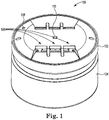
- Figures 1-5 illustrate different views of a lighting apparatus (device) in accordance with the present disclosure. It is noted that lighting apparatuses in accordance with embodiments herein are not limited to the example shown in Figures 1-5 . As will be appreciated, elements shown in the various embodiments herein can be added, exchanged, combined, and/or eliminated so as to provide a number of additional embodiments of the present disclosure. The proportion and the relative scale of the elements provided in the figures are intended to illustrate the embodiments of the present disclosure, and should not be taken in a limiting sense.
- the device 100 can be generally cylindrical in shape and can include a top portion 102 (hereinafter “top 102”) and a base portion 104 (hereinafter “base 104"). Visible on the exterior surfaces of the device 100 are a number of light emitting elements 106, a tool receiver 110 (hereinafter “socket 110"), and an opening 108 (hereinafter “pin hole 108").
- the top 102 and/or the base 104 can be made of metal, for instance, such as stainless steel. It is to be appreciated that other materials may be used.
- the light emitting elements 106 can include bulbs, diodes, and/or other lighting devices, and are not intended to be limited herein to a particular type and/or number of light emitting element.
- the base 104 can be embedded in a runway, for instance (e.g., concrete). In some embodiments, the base 104 is located entirely below a surface of a runway. In some embodiments, the base 104 can include an anchoring feature to allow for improved securing in the runway (not shown in Figures 1-5 ).
- a bottom portion of the base 104 can include a bulbous end and/or an hourglass shape.
- the top 102 can extend above the surface of the runway by a particular amount (e.g., to a maximum of 6.3 millimeters).
- the top 102 can be detached from the base 104.
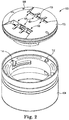
- the base 104 can include a number of surfaces defining a number of slots 114.
- Each of the slots 114 can include a vertical portion and an adjoining horizontal portion.
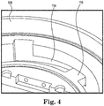
- the slots can be sized to accommodate keys 116 of the top 102 (seen in Fig. 4 ), for instance.
- the base can include a spring-loaded pin 112 extending vertically upward.
- the pin 112 can be biased in a raised position by a spring 118, shown in Figure 3 , such that the pin 112 protrudes from an interior surface of the base 104.
- the keys 116 can slide into corresponding slots 114 in the base portion 104. Once the keys 116 are inserted downward through the vertical portion of the slots, the top 102 can be rotated (e.g., using a tool 120, shown in Figure 5 ), and the keys 116 can slide through the horizontal portion of the slots 114 until rotation terminates at the end of the slots 114 (as shown in Figure 4 ). A distance of the horizontal portion of the slots 114 equate to between a 25 and 45 degree rotation of the top portion 102.
- the pin 112 in the base 104 can be pressed and held downward by a bottom surface of the top 102.
- the pin 112 aligns with the pin hole 108 in the top 102 and the spring 118 can force the pin through the pin hole 108 (e.g., through a portion of the pin hole 108).
- the top 102 and the base 104 can be secured together such that movement between the two is prevented in all directions.
- the top 102 can be removed from the base 104 by depressing the pin 112 through the pin hole 108 (e.g., via an elongate tool) and rotating the top portion in the reverse direction until the pin 112 no longer aligns with the pin hole 108. Further rotation of the top 102 such that the keys 116 slide back through the horizontal portion of the slots 114 into the vertical portion of the slots can be carried out with the aid of a tool 120, for instance.
- a screwdriver e.g., having a diameter of 5 millimeters
- a socket wrench can be used to rotate the top 102, though embodiments herein are not so limited.
- the top 102 can include 2 keys 116 on opposing sides. In some embodiments, the top 102 can include 2 keys, wherein one key 116 is located on a first side and another key 116 is offset 25 degrees from the opposite side. In some embodiments, the base 104 can include two pins 112, and the top can include two corresponding pin holes 108, though it is noted that other quantities of these components are in accordance with embodiments of the present disclosure.
- an O-ring or gasket can be located between a portion of the top 102 and the base 104 to prevent moisture and/or other materials from reaching internal areas of the device 100.
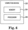
- FIG. 6 illustrates a computing device 222 for runway lighting in accordance with one or more embodiments of the present disclosure.
- Computing device 222 can be, for example, a laptop computer, a desktop computer, or a mobile device (e.g., a mobile phone, a personal digital assistant, etc.), among other types of computing devices.
- the computing device can be connected to the lighting apparatus 100 via a wired and/or wireless connection.
- computing device 222 includes a memory 224 and a processor 226 coupled to memory 224.
- Memory 224 can be any type of storage medium that can be accessed by processor 226 to perform various examples of the present disclosure.
- memory 224 can be a non-transitory computer readable medium having computer readable instructions (e.g., computer program instructions) stored thereon that are executable by processor 226 to provide runway lighting by controlling a number of operations of the lighting apparatus 100 in accordance with one or more embodiments of the present disclosure.
- Memory 224 can be volatile or nonvolatile memory. Memory 224 can also be removable (e.g., portable) memory, or non-removable (e.g., internal) memory.
- memory 224 can be random access memory (RAM) (e.g., dynamic random access memory (DRAM) and/or phase change random access memory (PCRAM)), read-only memory (ROM) (e.g., electrically erasable programmable read-only memory (EEPROM) and/or compact-disc read-only memory (CD-ROM)), flash memory, a laser disc, a digital versatile disc (DVD) or other optical disk storage, and/or a magnetic medium such as magnetic cassettes, tapes, or disks, among other types of memory.
- RAM random access memory
- DRAM dynamic random access memory
- PCRAM phase change random access memory
- ROM read-only memory
- EEPROM electrically erasable programmable read-only memory
- CD-ROM compact-disc read-only memory
- flash memory a laser disc, a digital
- memory 224 is illustrated as being located in computing device 222, embodiments of the present disclosure are not so limited.
- memory 224 can also be located internal to another computing resource (e.g., enabling computer readable instructions to be downloaded over the Internet or another wired or wireless connection).
Landscapes
- Engineering & Computer Science (AREA)
- General Engineering & Computer Science (AREA)
- Physics & Mathematics (AREA)
- Acoustics & Sound (AREA)
- Mechanical Engineering (AREA)
- Aviation & Aerospace Engineering (AREA)
- Non-Portable Lighting Devices Or Systems Thereof (AREA)
Claims (10)
- Landebahnbeleuchtungsvorrichtung (100), umfassend:einen Kopfabschnitt (102), der eine Vielzahl Licht emittierender Elemente (106), eine Vielzahl seitlicher Vorsprünge (116) und eine Werkzeugaufnahme (110) auf einer Außenfläche des Kopfabschnitts (102) beinhaltet, undeinen Sockelabschnitt (104), der eine Vielzahl von Flächen beinhaltet, die eine Vielzahl von Schlitzen (114) definieren,wobei jeder Schlitz (114) dafür konfiguriert ist, einen der Vielzahl seitlicher Vorsprünge (116) aufzunehmen, um den Kopfabschnitt (102) an dem Sockelabschnitt (104) zu sichern,wobei jeder Schlitz (114) einen vertikalen Abschnitt und einen horizontalen Abschnitt beinhaltet undwobei eine Strecke des horizontalen Abschnitts jedes jeweiligen Schlitzes (114) einer Drehung des Kopfabschnitts (102) zwischen 25 Grad und 45 Grad entspricht, um den Kopfabschnitt (102) an dem Sockelabschnitt (104) zu sichern.
- Vorrichtung (100) nach Anspruch 1, wobei der vertikale Abschnitt jedes jeweiligen Schlitzes (114) an dem horizontalen Abschnitt des jeweiligen Schlitzes (114) endet.
- Vorrichtung (100) nach Anspruch 2, wobei der Sockelabschnitt (104) einen Stift (112) beinhaltet und wobei der Kopfabschnitt (102) eine Fläche beinhaltet, die eine zum Aufnehmen des Stifts (112) konfigurierte Öffnung (108) definiert.
- Vorrichtung (100) nach Anspruch 3,
wobei der Stift (112) durch eine Feder (118) in eine angehobene Position vorgespannt ist. - Vorrichtung (100) nach Anspruch 4,
wobei die Öffnung (108) dafür konfiguriert ist, den Stift (112) aufzunehmen, wenn sich jeder der Vielzahl seitlicher Vorsprünge (116) an einem jeweiligen Ende eines horizontalen Abschnitts eines jeweiligen Schlitzes (114) der Vielzahl von Schlitzen (114) befindet. - Vorrichtung (100) nach Anspruch 1, wobei die Vielzahl seitlicher Vorsprünge (116) einen ersten seitlichen Vorsprung (116) umfasst, der einem zweiten seitlichen Vorsprung (116) direkt entgegengesetzt ist.
- Vorrichtung (100) nach Anspruch 1, wobei die Vielzahl seitlicher Vorsprünge (116) einen ersten seitlichen Vorsprung (116) und einen zweiten seitlichen Vorsprung (116) umfasst, der zu einer dem ersten seitlichen Vorsprung (116) direkt entgegengesetzten Position versetzt ist.
- Vorrichtung (100) nach Anspruch 1, wobei der Sockelabschnitt (104) dafür konfiguriert ist, unterhalb einer Oberfläche einer Landebahn gesichert zu werden.
- Verfahren zum Bereitstellen einer Landebahnbeleuchtung, umfassend:Bereitstellen eines Kopfabschnitts (102), wobei der Kopfabschnitt (102) eine Vielzahl Licht emittierender Elemente (106) und eine Vielzahl seitlicher Vorsprünge (116) beinhaltet, undBereitstellen eines Sockelabschnitts (104), wobei der Sockelabschnitt (104) eine Vielzahl von Flächen beinhaltet, die eine Vielzahl von Schlitzen (114) definieren, wobei jeder Schlitz (114) dafür konfiguriert ist, einen der Vielzahl seitlicher Vorsprünge (116) aufzunehmen,Einsetzen des Kopfabschnitts (102) in den Sockelabschnitt (104) derart, dass die Vielzahl seitlicher Vorsprünge (116) abwärts durch vertikale Abschnitte der Vielzahl von Schlitzen (114) läuft, undmittels eines teilweise in eine Werkzeugaufnahme (110) auf einer Außenfläche des Kopfabschnitts (102) eingesetzten Werkzeugs (120) erfolgendes Drehen des Kopfabschnitts (102) in einer ersten Richtung zwischen 25 Grad und 45 Grad derart, dass die Vielzahl seitlicher Vorsprünge (116) horizontale Abschnitte der Vielzahl von Schlitzen (114) durchläuft, bis ein Stift (112) des Sockelabschnitts (104) durch eine Öffnung (108) des Kopfabschnitts (102) tritt, um eine Landebahnbeleuchtungsvorrichtung (100) bereitzustellen.
- Verfahren nach Anspruch 9, wobei das Verfahren ferner Folgendes beinhaltet:Herabdrücken des Stifts (112) des Sockelabschnitts (104) derart, dass der Stift (112) nicht mehr durch die Öffnung (108) des Kopfabschnitts (102) tritt,Drehen des Kopfabschnitts (102) in einer zweiten Richtung derart, dass die Vielzahl seitlicher Vorsprünge (116) durch die horizontalen Abschnitte der Vielzahl von Schlitzen (114) zurückläuft, undAbnehmen des Kopfabschnitts (102) von dem Sockelabschnitt (104) derart, dass die Vielzahl seitlicher Vorsprünge (116) aufwärts durch vertikale Abschnitte der Vielzahl von Schlitzen (114) läuft.
Applications Claiming Priority (1)
| Application Number | Priority Date | Filing Date | Title |
|---|---|---|---|
| US201662431646P | 2016-12-08 | 2016-12-08 |
Publications (2)
| Publication Number | Publication Date |
|---|---|
| EP3333435A1 EP3333435A1 (de) | 2018-06-13 |
| EP3333435B1 true EP3333435B1 (de) | 2020-02-12 |
Family
ID=60569701
Family Applications (1)
| Application Number | Title | Priority Date | Filing Date |
|---|---|---|---|
| EP17204765.6A Active EP3333435B1 (de) | 2016-12-08 | 2017-11-30 | Landebahnbeleuchtung |
Country Status (3)
| Country | Link |
|---|---|
| US (1) | US10501206B2 (de) |
| EP (1) | EP3333435B1 (de) |
| CN (1) | CN108180422A (de) |
Families Citing this family (5)
| Publication number | Priority date | Publication date | Assignee | Title |
|---|---|---|---|---|
| CN109163243A (zh) * | 2018-06-29 | 2019-01-08 | 铜陵祥意和贸易有限责任公司 | 一种户外用安装于地面的筒灯 |
| US11420767B2 (en) * | 2018-10-26 | 2022-08-23 | HotaluX, Ltd. | Runway-embedded flash lighting device and heat conducting member |
| EP3872390B1 (de) | 2018-10-26 | 2024-08-28 | HotaluX, Ltd. | In rollfeld eingebettete blitzlichtvorrichtung |
| JP7360173B2 (ja) * | 2018-10-26 | 2023-10-12 | 株式会社ホタルクス | 滑走路埋込型閃光装置 |
| US12492805B1 (en) * | 2024-06-11 | 2025-12-09 | Honeywell International Inc. | Securing a light assembly of an airfield light |
Family Cites Families (18)
| Publication number | Priority date | Publication date | Assignee | Title |
|---|---|---|---|---|
| US2854274A (en) | 1955-08-30 | 1958-09-30 | North American Aviation Inc | Pressure reservoir cap |
| US3113726A (en) * | 1960-08-30 | 1963-12-10 | Westinghouse Electric Corp | Runway lighting unit |
| CH672830A5 (de) * | 1987-03-16 | 1989-12-29 | Meta Fer Ag | |
| US6840649B2 (en) * | 1998-07-10 | 2005-01-11 | Gary L. Reinert, Sr. | Stainless steel airport light container apparatus and method |
| US6669351B1 (en) * | 1999-10-21 | 2003-12-30 | Cooper Industries, Inc. | Airport in-pavement lighting fixture |
| JP3995434B2 (ja) | 2001-07-23 | 2007-10-24 | 株式会社ユーシン | ステアリングロック装置 |
| DE20203550U1 (de) * | 2002-03-05 | 2002-07-18 | Gläser, Dietmar, 97519 Riedbach | Werkzeugloses Befestigungssystem von Bauteilen, z.B. Leuchten, in der Haustechnik |
| TW542393U (en) | 2002-09-17 | 2003-07-11 | Lite On It Corp | Ejecting and locking device for lifting lid of external type CD drive |
| US6929226B1 (en) | 2003-08-11 | 2005-08-16 | The United States Of America As Represented By The Secretary Of The Army | Twist lock mounting system |
| US7198098B2 (en) * | 2004-04-22 | 2007-04-03 | Williams John R | Mechanical connection system |
| WO2009081382A1 (en) * | 2007-12-22 | 2009-07-02 | Philips Solid-State Lighting Solutions Inc. | Led-based luminaires for large-scale architectural illumination |
| CN101660695A (zh) * | 2009-09-15 | 2010-03-03 | 陈鸿蛟 | 一种led埋地灯 |
| WO2014111541A1 (en) * | 2013-01-18 | 2014-07-24 | Adb Bvba | Modular inset light container |
| JP6211909B2 (ja) | 2013-12-02 | 2017-10-11 | 株式会社ニフコ | リッド装置 |
| CN105098551B (zh) * | 2014-05-19 | 2019-01-25 | 朗德万斯公司 | 连接器装置和包括该连接器装置的照明装置 |
| US9853413B2 (en) * | 2014-11-12 | 2017-12-26 | Tae Jin Kim | Airport runway approach lighting apparatus |
| US20160281965A1 (en) * | 2015-03-24 | 2016-09-29 | Cooper Technologies Company | Bolt-less Inset Light Fixture & Base |
| CN205782391U (zh) * | 2016-05-20 | 2016-12-07 | 中山市和城照明电器有限公司 | 一种采用分体式光源的筒灯 |
-
2017
- 2017-11-30 EP EP17204765.6A patent/EP3333435B1/de active Active
- 2017-12-05 US US15/832,167 patent/US10501206B2/en active Active
- 2017-12-08 CN CN201711289890.2A patent/CN108180422A/zh active Pending
Non-Patent Citations (1)
| Title |
|---|
| KENNEDY ROAD WINDSOR ET AL: "Eaton Crouse-Hinds Series Airport Lighting Products Instruction Manual", 13 July 2016 (2016-07-13), XP055563162, Retrieved from the Internet <URL:http://www.cooperindustries.com/content/dam/public/crousehinds/airport-lighting/product-manuals/9929.pdf> * |
Also Published As
| Publication number | Publication date |
|---|---|
| CN108180422A (zh) | 2018-06-19 |
| US10501206B2 (en) | 2019-12-10 |
| EP3333435A1 (de) | 2018-06-13 |
| US20180162554A1 (en) | 2018-06-14 |
Similar Documents
| Publication | Publication Date | Title |
|---|---|---|
| EP3333435B1 (de) | Landebahnbeleuchtung | |
| CN101784802A (zh) | 铆接螺钉及其用于将钻孔格板临时地固定于待组装元件的应用 | |
| US9689634B2 (en) | Firearm magazine securing apparatus, method and kit | |
| AU2011100145A4 (en) | Adjustable wall hanger | |
| DK2909489T3 (en) | ANCHORED MOVING DEVICE | |
| US10371362B2 (en) | Runway fixture ring | |
| US20150168245A1 (en) | Torque tool calibration fixture | |
| CN104428087A (zh) | 连结装置和切削工具 | |
| US20160151890A1 (en) | Clamp device | |
| CN109311638A (zh) | 轨道固定装置 | |
| US20150224350A1 (en) | Safety harness anchoring system | |
| US8925211B2 (en) | Laser-based alignment device and associated methods thereof | |
| US2393447A (en) | Turbine blade locking apparatus | |
| JP2014081380A (ja) | 位置決め機構及び位置決め方法 | |
| US20170306689A1 (en) | Inspection device and method for use | |
| JP2015230055A (ja) | 支持脚 | |
| US2390173A (en) | Lock fastener | |
| US20170276292A1 (en) | Tilt prevention structure for test seat | |
| CA2957212A1 (en) | Securing device | |
| JP2015182200A (ja) | 位置決め装置 | |
| ES2632166B1 (es) | Dispositivo de mecanizado de superficies laminares curvas | |
| US11940002B2 (en) | Adjustable potted insert | |
| US9689460B2 (en) | Diaper pin vibration damper | |
| JP6133243B2 (ja) | 標示板 | |
| US10208447B1 (en) | Apparatus and method for stabilizing cracks and joints |
Legal Events
| Date | Code | Title | Description |
|---|---|---|---|
| PUAI | Public reference made under article 153(3) epc to a published international application that has entered the european phase |
Free format text: ORIGINAL CODE: 0009012 |
|
| STAA | Information on the status of an ep patent application or granted ep patent |
Free format text: STATUS: REQUEST FOR EXAMINATION WAS MADE |
|
| 17P | Request for examination filed |
Effective date: 20171130 |
|
| AK | Designated contracting states |
Kind code of ref document: A1 Designated state(s): AL AT BE BG CH CY CZ DE DK EE ES FI FR GB GR HR HU IE IS IT LI LT LU LV MC MK MT NL NO PL PT RO RS SE SI SK SM TR |
|
| AX | Request for extension of the european patent |
Extension state: BA ME |
|
| STAA | Information on the status of an ep patent application or granted ep patent |
Free format text: STATUS: EXAMINATION IS IN PROGRESS |
|
| 17Q | First examination report despatched |
Effective date: 20180903 |
|
| GRAP | Despatch of communication of intention to grant a patent |
Free format text: ORIGINAL CODE: EPIDOSNIGR1 |
|
| STAA | Information on the status of an ep patent application or granted ep patent |
Free format text: STATUS: GRANT OF PATENT IS INTENDED |
|
| INTG | Intention to grant announced |
Effective date: 20190927 |
|
| RIN1 | Information on inventor provided before grant (corrected) |
Inventor name: ALVAREZ, OSCAR Inventor name: MARQUEZ, JOSE FRANCISCO Inventor name: LANGSTON, TODD |
|
| GRAS | Grant fee paid |
Free format text: ORIGINAL CODE: EPIDOSNIGR3 |
|
| GRAA | (expected) grant |
Free format text: ORIGINAL CODE: 0009210 |
|
| STAA | Information on the status of an ep patent application or granted ep patent |
Free format text: STATUS: THE PATENT HAS BEEN GRANTED |
|
| AK | Designated contracting states |
Kind code of ref document: B1 Designated state(s): AL AT BE BG CH CY CZ DE DK EE ES FI FR GB GR HR HU IE IS IT LI LT LU LV MC MK MT NL NO PL PT RO RS SE SI SK SM TR |
|
| REG | Reference to a national code |
Ref country code: GB Ref legal event code: FG4D |
|
| REG | Reference to a national code |
Ref country code: CH Ref legal event code: EP |
|
| REG | Reference to a national code |
Ref country code: AT Ref legal event code: REF Ref document number: 1232490 Country of ref document: AT Kind code of ref document: T Effective date: 20200215 |
|
| REG | Reference to a national code |
Ref country code: IE Ref legal event code: FG4D |
|
| REG | Reference to a national code |
Ref country code: DE Ref legal event code: R096 Ref document number: 602017011582 Country of ref document: DE |
|
| PG25 | Lapsed in a contracting state [announced via postgrant information from national office to epo] |
Ref country code: NO Free format text: LAPSE BECAUSE OF FAILURE TO SUBMIT A TRANSLATION OF THE DESCRIPTION OR TO PAY THE FEE WITHIN THE PRESCRIBED TIME-LIMIT Effective date: 20200512 Ref country code: RS Free format text: LAPSE BECAUSE OF FAILURE TO SUBMIT A TRANSLATION OF THE DESCRIPTION OR TO PAY THE FEE WITHIN THE PRESCRIBED TIME-LIMIT Effective date: 20200212 Ref country code: FI Free format text: LAPSE BECAUSE OF FAILURE TO SUBMIT A TRANSLATION OF THE DESCRIPTION OR TO PAY THE FEE WITHIN THE PRESCRIBED TIME-LIMIT Effective date: 20200212 |
|
| REG | Reference to a national code |
Ref country code: LT Ref legal event code: MG4D |
|
| REG | Reference to a national code |
Ref country code: NL Ref legal event code: MP Effective date: 20200212 |
|
| PG25 | Lapsed in a contracting state [announced via postgrant information from national office to epo] |
Ref country code: BG Free format text: LAPSE BECAUSE OF FAILURE TO SUBMIT A TRANSLATION OF THE DESCRIPTION OR TO PAY THE FEE WITHIN THE PRESCRIBED TIME-LIMIT Effective date: 20200512 Ref country code: IS Free format text: LAPSE BECAUSE OF FAILURE TO SUBMIT A TRANSLATION OF THE DESCRIPTION OR TO PAY THE FEE WITHIN THE PRESCRIBED TIME-LIMIT Effective date: 20200612 Ref country code: GR Free format text: LAPSE BECAUSE OF FAILURE TO SUBMIT A TRANSLATION OF THE DESCRIPTION OR TO PAY THE FEE WITHIN THE PRESCRIBED TIME-LIMIT Effective date: 20200513 Ref country code: HR Free format text: LAPSE BECAUSE OF FAILURE TO SUBMIT A TRANSLATION OF THE DESCRIPTION OR TO PAY THE FEE WITHIN THE PRESCRIBED TIME-LIMIT Effective date: 20200212 Ref country code: LV Free format text: LAPSE BECAUSE OF FAILURE TO SUBMIT A TRANSLATION OF THE DESCRIPTION OR TO PAY THE FEE WITHIN THE PRESCRIBED TIME-LIMIT Effective date: 20200212 Ref country code: SE Free format text: LAPSE BECAUSE OF FAILURE TO SUBMIT A TRANSLATION OF THE DESCRIPTION OR TO PAY THE FEE WITHIN THE PRESCRIBED TIME-LIMIT Effective date: 20200212 |
|
| PG25 | Lapsed in a contracting state [announced via postgrant information from national office to epo] |
Ref country code: NL Free format text: LAPSE BECAUSE OF FAILURE TO SUBMIT A TRANSLATION OF THE DESCRIPTION OR TO PAY THE FEE WITHIN THE PRESCRIBED TIME-LIMIT Effective date: 20200212 |
|
| PG25 | Lapsed in a contracting state [announced via postgrant information from national office to epo] |
Ref country code: ES Free format text: LAPSE BECAUSE OF FAILURE TO SUBMIT A TRANSLATION OF THE DESCRIPTION OR TO PAY THE FEE WITHIN THE PRESCRIBED TIME-LIMIT Effective date: 20200212 Ref country code: PT Free format text: LAPSE BECAUSE OF FAILURE TO SUBMIT A TRANSLATION OF THE DESCRIPTION OR TO PAY THE FEE WITHIN THE PRESCRIBED TIME-LIMIT Effective date: 20200705 Ref country code: LT Free format text: LAPSE BECAUSE OF FAILURE TO SUBMIT A TRANSLATION OF THE DESCRIPTION OR TO PAY THE FEE WITHIN THE PRESCRIBED TIME-LIMIT Effective date: 20200212 Ref country code: RO Free format text: LAPSE BECAUSE OF FAILURE TO SUBMIT A TRANSLATION OF THE DESCRIPTION OR TO PAY THE FEE WITHIN THE PRESCRIBED TIME-LIMIT Effective date: 20200212 Ref country code: CZ Free format text: LAPSE BECAUSE OF FAILURE TO SUBMIT A TRANSLATION OF THE DESCRIPTION OR TO PAY THE FEE WITHIN THE PRESCRIBED TIME-LIMIT Effective date: 20200212 Ref country code: SK Free format text: LAPSE BECAUSE OF FAILURE TO SUBMIT A TRANSLATION OF THE DESCRIPTION OR TO PAY THE FEE WITHIN THE PRESCRIBED TIME-LIMIT Effective date: 20200212 Ref country code: SM Free format text: LAPSE BECAUSE OF FAILURE TO SUBMIT A TRANSLATION OF THE DESCRIPTION OR TO PAY THE FEE WITHIN THE PRESCRIBED TIME-LIMIT Effective date: 20200212 Ref country code: EE Free format text: LAPSE BECAUSE OF FAILURE TO SUBMIT A TRANSLATION OF THE DESCRIPTION OR TO PAY THE FEE WITHIN THE PRESCRIBED TIME-LIMIT Effective date: 20200212 Ref country code: DK Free format text: LAPSE BECAUSE OF FAILURE TO SUBMIT A TRANSLATION OF THE DESCRIPTION OR TO PAY THE FEE WITHIN THE PRESCRIBED TIME-LIMIT Effective date: 20200212 |
|
| REG | Reference to a national code |
Ref country code: DE Ref legal event code: R097 Ref document number: 602017011582 Country of ref document: DE |
|
| REG | Reference to a national code |
Ref country code: AT Ref legal event code: MK05 Ref document number: 1232490 Country of ref document: AT Kind code of ref document: T Effective date: 20200212 |
|
| PLBE | No opposition filed within time limit |
Free format text: ORIGINAL CODE: 0009261 |
|
| STAA | Information on the status of an ep patent application or granted ep patent |
Free format text: STATUS: NO OPPOSITION FILED WITHIN TIME LIMIT |
|
| 26N | No opposition filed |
Effective date: 20201113 |
|
| PG25 | Lapsed in a contracting state [announced via postgrant information from national office to epo] |
Ref country code: IT Free format text: LAPSE BECAUSE OF FAILURE TO SUBMIT A TRANSLATION OF THE DESCRIPTION OR TO PAY THE FEE WITHIN THE PRESCRIBED TIME-LIMIT Effective date: 20200212 Ref country code: AT Free format text: LAPSE BECAUSE OF FAILURE TO SUBMIT A TRANSLATION OF THE DESCRIPTION OR TO PAY THE FEE WITHIN THE PRESCRIBED TIME-LIMIT Effective date: 20200212 |
|
| PG25 | Lapsed in a contracting state [announced via postgrant information from national office to epo] |
Ref country code: SI Free format text: LAPSE BECAUSE OF FAILURE TO SUBMIT A TRANSLATION OF THE DESCRIPTION OR TO PAY THE FEE WITHIN THE PRESCRIBED TIME-LIMIT Effective date: 20200212 Ref country code: PL Free format text: LAPSE BECAUSE OF FAILURE TO SUBMIT A TRANSLATION OF THE DESCRIPTION OR TO PAY THE FEE WITHIN THE PRESCRIBED TIME-LIMIT Effective date: 20200212 |
|
| PG25 | Lapsed in a contracting state [announced via postgrant information from national office to epo] |
Ref country code: MC Free format text: LAPSE BECAUSE OF FAILURE TO SUBMIT A TRANSLATION OF THE DESCRIPTION OR TO PAY THE FEE WITHIN THE PRESCRIBED TIME-LIMIT Effective date: 20200212 |
|
| REG | Reference to a national code |
Ref country code: CH Ref legal event code: PL |
|
| PG25 | Lapsed in a contracting state [announced via postgrant information from national office to epo] |
Ref country code: LU Free format text: LAPSE BECAUSE OF NON-PAYMENT OF DUE FEES Effective date: 20201130 |
|
| REG | Reference to a national code |
Ref country code: BE Ref legal event code: MM Effective date: 20201130 |
|
| PG25 | Lapsed in a contracting state [announced via postgrant information from national office to epo] |
Ref country code: LI Free format text: LAPSE BECAUSE OF NON-PAYMENT OF DUE FEES Effective date: 20201130 Ref country code: CH Free format text: LAPSE BECAUSE OF NON-PAYMENT OF DUE FEES Effective date: 20201130 |
|
| REG | Reference to a national code |
Ref country code: IE Ref legal event code: MM4A |
|
| PG25 | Lapsed in a contracting state [announced via postgrant information from national office to epo] |
Ref country code: IE Free format text: LAPSE BECAUSE OF NON-PAYMENT OF DUE FEES Effective date: 20201130 |
|
| PG25 | Lapsed in a contracting state [announced via postgrant information from national office to epo] |
Ref country code: TR Free format text: LAPSE BECAUSE OF FAILURE TO SUBMIT A TRANSLATION OF THE DESCRIPTION OR TO PAY THE FEE WITHIN THE PRESCRIBED TIME-LIMIT Effective date: 20200212 Ref country code: MT Free format text: LAPSE BECAUSE OF FAILURE TO SUBMIT A TRANSLATION OF THE DESCRIPTION OR TO PAY THE FEE WITHIN THE PRESCRIBED TIME-LIMIT Effective date: 20200212 Ref country code: CY Free format text: LAPSE BECAUSE OF FAILURE TO SUBMIT A TRANSLATION OF THE DESCRIPTION OR TO PAY THE FEE WITHIN THE PRESCRIBED TIME-LIMIT Effective date: 20200212 |
|
| PG25 | Lapsed in a contracting state [announced via postgrant information from national office to epo] |
Ref country code: MK Free format text: LAPSE BECAUSE OF FAILURE TO SUBMIT A TRANSLATION OF THE DESCRIPTION OR TO PAY THE FEE WITHIN THE PRESCRIBED TIME-LIMIT Effective date: 20200212 Ref country code: AL Free format text: LAPSE BECAUSE OF FAILURE TO SUBMIT A TRANSLATION OF THE DESCRIPTION OR TO PAY THE FEE WITHIN THE PRESCRIBED TIME-LIMIT Effective date: 20200212 |
|
| PG25 | Lapsed in a contracting state [announced via postgrant information from national office to epo] |
Ref country code: BE Free format text: LAPSE BECAUSE OF NON-PAYMENT OF DUE FEES Effective date: 20201130 |
|
| P01 | Opt-out of the competence of the unified patent court (upc) registered |
Effective date: 20230523 |
|
| PGFP | Annual fee paid to national office [announced via postgrant information from national office to epo] |
Ref country code: FR Payment date: 20241126 Year of fee payment: 8 |
|
| PGFP | Annual fee paid to national office [announced via postgrant information from national office to epo] |
Ref country code: DE Payment date: 20251126 Year of fee payment: 9 |
|
| PGFP | Annual fee paid to national office [announced via postgrant information from national office to epo] |
Ref country code: GB Payment date: 20251125 Year of fee payment: 9 |