EP3333386A1 - Système de dissolution de dépôt d'injecteur et procédé - Google Patents
Système de dissolution de dépôt d'injecteur et procédé Download PDFInfo
- Publication number
- EP3333386A1 EP3333386A1 EP16203403.7A EP16203403A EP3333386A1 EP 3333386 A1 EP3333386 A1 EP 3333386A1 EP 16203403 A EP16203403 A EP 16203403A EP 3333386 A1 EP3333386 A1 EP 3333386A1
- Authority
- EP
- European Patent Office
- Prior art keywords
- reductant
- supply line
- injection system
- injector
- inlet
- Prior art date
- Legal status (The legal status is an assumption and is not a legal conclusion. Google has not performed a legal analysis and makes no representation as to the accuracy of the status listed.)
- Granted
Links
Images


Classifications
-
- F—MECHANICAL ENGINEERING; LIGHTING; HEATING; WEAPONS; BLASTING
- F01—MACHINES OR ENGINES IN GENERAL; ENGINE PLANTS IN GENERAL; STEAM ENGINES
- F01N—GAS-FLOW SILENCERS OR EXHAUST APPARATUS FOR MACHINES OR ENGINES IN GENERAL; GAS-FLOW SILENCERS OR EXHAUST APPARATUS FOR INTERNAL-COMBUSTION ENGINES
- F01N3/00—Exhaust or silencing apparatus having means for purifying, rendering innocuous, or otherwise treating exhaust
- F01N3/08—Exhaust or silencing apparatus having means for purifying, rendering innocuous, or otherwise treating exhaust for rendering innocuous
- F01N3/10—Exhaust or silencing apparatus having means for purifying, rendering innocuous, or otherwise treating exhaust for rendering innocuous by thermal or catalytic conversion of noxious components of exhaust
- F01N3/24—Exhaust or silencing apparatus having means for purifying, rendering innocuous, or otherwise treating exhaust for rendering innocuous by thermal or catalytic conversion of noxious components of exhaust characterised by constructional aspects of converting apparatus
-
- F—MECHANICAL ENGINEERING; LIGHTING; HEATING; WEAPONS; BLASTING
- F01—MACHINES OR ENGINES IN GENERAL; ENGINE PLANTS IN GENERAL; STEAM ENGINES
- F01N—GAS-FLOW SILENCERS OR EXHAUST APPARATUS FOR MACHINES OR ENGINES IN GENERAL; GAS-FLOW SILENCERS OR EXHAUST APPARATUS FOR INTERNAL-COMBUSTION ENGINES
- F01N3/00—Exhaust or silencing apparatus having means for purifying, rendering innocuous, or otherwise treating exhaust
- F01N3/08—Exhaust or silencing apparatus having means for purifying, rendering innocuous, or otherwise treating exhaust for rendering innocuous
- F01N3/10—Exhaust or silencing apparatus having means for purifying, rendering innocuous, or otherwise treating exhaust for rendering innocuous by thermal or catalytic conversion of noxious components of exhaust
- F01N3/18—Exhaust or silencing apparatus having means for purifying, rendering innocuous, or otherwise treating exhaust for rendering innocuous by thermal or catalytic conversion of noxious components of exhaust characterised by methods of operation; Control
- F01N3/20—Exhaust or silencing apparatus having means for purifying, rendering innocuous, or otherwise treating exhaust for rendering innocuous by thermal or catalytic conversion of noxious components of exhaust characterised by methods of operation; Control specially adapted for catalytic conversion
- F01N3/206—Adding periodically or continuously substances to exhaust gases for promoting purification, e.g. catalytic material in liquid form, NOx reducing agents
- F01N3/2066—Selective catalytic reduction [SCR]
-
- F—MECHANICAL ENGINEERING; LIGHTING; HEATING; WEAPONS; BLASTING
- F01—MACHINES OR ENGINES IN GENERAL; ENGINE PLANTS IN GENERAL; STEAM ENGINES
- F01N—GAS-FLOW SILENCERS OR EXHAUST APPARATUS FOR MACHINES OR ENGINES IN GENERAL; GAS-FLOW SILENCERS OR EXHAUST APPARATUS FOR INTERNAL-COMBUSTION ENGINES
- F01N2470/00—Structure or shape of exhaust gas passages, pipes or tubes
-
- F—MECHANICAL ENGINEERING; LIGHTING; HEATING; WEAPONS; BLASTING
- F01—MACHINES OR ENGINES IN GENERAL; ENGINE PLANTS IN GENERAL; STEAM ENGINES
- F01N—GAS-FLOW SILENCERS OR EXHAUST APPARATUS FOR MACHINES OR ENGINES IN GENERAL; GAS-FLOW SILENCERS OR EXHAUST APPARATUS FOR INTERNAL-COMBUSTION ENGINES
- F01N2610/00—Adding substances to exhaust gases
- F01N2610/02—Adding substances to exhaust gases the substance being ammonia or urea
-
- F—MECHANICAL ENGINEERING; LIGHTING; HEATING; WEAPONS; BLASTING
- F01—MACHINES OR ENGINES IN GENERAL; ENGINE PLANTS IN GENERAL; STEAM ENGINES
- F01N—GAS-FLOW SILENCERS OR EXHAUST APPARATUS FOR MACHINES OR ENGINES IN GENERAL; GAS-FLOW SILENCERS OR EXHAUST APPARATUS FOR INTERNAL-COMBUSTION ENGINES
- F01N2610/00—Adding substances to exhaust gases
- F01N2610/14—Arrangements for the supply of substances, e.g. conduits
- F01N2610/1493—Purging the reducing agent out of the conduits or nozzle
-
- Y—GENERAL TAGGING OF NEW TECHNOLOGICAL DEVELOPMENTS; GENERAL TAGGING OF CROSS-SECTIONAL TECHNOLOGIES SPANNING OVER SEVERAL SECTIONS OF THE IPC; TECHNICAL SUBJECTS COVERED BY FORMER USPC CROSS-REFERENCE ART COLLECTIONS [XRACs] AND DIGESTS
- Y02—TECHNOLOGIES OR APPLICATIONS FOR MITIGATION OR ADAPTATION AGAINST CLIMATE CHANGE
- Y02T—CLIMATE CHANGE MITIGATION TECHNOLOGIES RELATED TO TRANSPORTATION
- Y02T10/00—Road transport of goods or passengers
- Y02T10/10—Internal combustion engine [ICE] based vehicles
- Y02T10/12—Improving ICE efficiencies
Definitions
- the present disclosure generally relates to an SCR injection system, and in particular to a system and method for dissolving deposits of crystallized reductant in an injector of such an SCR injection system.
- Engine systems for vehicles and the like may comprise an aftertreatment module for removing unwanted gaseous emissions or pollutants from the exhaust gases of an internal combustion engine.
- a selective catalytic reduction (SCR) system may be provided in the exhaust gas stream for removing nitrogen oxides (NOx).
- an SCR system comprises a reductant injector reaching into a mixing pipe located upstream of a catalyst.
- the reductant injector may inject a liquid reductant into the exhaust gases before they contact the catalyst.
- Suitable liquid reductants may include anhydrous ammonia, aqueous ammonia and urea.
- the high temperature of the exhaust gases may evaporate the liquid reductant, and upon contact with the catalyst, the gaseous reductant may react with the NOx in the exhaust gas to form nitrogen and water.
- the reductant may be deposited as solid compounds on components of the SCR system.
- the reductant may be deposited on or around an outlet nozzle of the reductant injector when eddy currents in the exhaust gas flow redirect injected reductant back onto the outlet nozzle.
- the reductant may crystallize and form deposits inside the reductant injector.
- WO 2015/153350 A1 discloses an anti-clogging device for a diesel exhaust fluid (DEF) supply, wherein a reservoir for air trapped in a feed line for supplying DEF to a dosing module is placed vertically above the dosing module.
- DEF diesel exhaust fluid
- the present disclosure is directed, at least in part, to improving or overcoming one or more aspects of prior systems.
- the present disclosure relates to an SCR injection system for an internal combustion engine.
- the SCR injection system comprises a reductant injector having a housing, a reductant inlet formed in the housing, and a reductant supply line.
- the reductant supply line is fluidly connected to the reductant inlet and configured to supply reductant to the reductant injector.
- the reductant supply line includes a downwardly inclined portion extending towards the reductant injector. The downwardly inclined portion is disposed at least in part above the reductant inlet of the reductant injector with respect to a horizontal datum line passing through the reductant inlet.
- the present disclosure relates to an engine system comprising an internal combustion engine and an SCR injection system.
- the SCR injection system comprises a reductant injector having a housing, a reductant inlet formed in the housing, and a reductant supply line.
- the reductant supply line is fluidly connected to the reductant inlet and configured to supply reductant to the reductant injector.
- the reductant supply line includes a downwardly inclined portion extending towards the reductant injector. The downwardly inclined portion is disposed at least in part above the reductant inlet of the reductant injector with respect to a horizontal datum line passing through the reductant inlet.
- the present disclosure relates to an SCR injection system for an internal combustion engine.
- the SCR injection system comprises a reductant injector having a housing, a reductant inlet formed in the housing and a reductant supply line fluidly connected to the reductant inlet for supplying reductant to the reductant injector.
- the SCR injection system further comprises an air release valve arranged in the reductant supply line or the reductant injector and configured to be actuated to allow air in the reductant supply line to escape from the system.
- a control unit may be configured to open the air release valve at a predetermined timing associated with a priming operation of the SCR injection system, or based on a detection by at least one sensor, for example, a fluid sensor and/or a pressure sensor disposed in the SCR injection system.
- the control unit may further be configured to close the air release valve after lapse of a predetermined time interval from initiating the priming operation, or based on a detection by at least one sensor, for example, a fluid sensor and/or a pressure sensor disposed in the SCR injection system.
- the present disclosure is based in part on the realization that deposits in a reductant injector, in particular, crystallized reductant, may cause the reductant injector to stick, which may result in a failure of the associated SCR injection system. It has been realized that one possibility to dissolve the crystals formed in the reductant injector is to supply reductant fluid to the injector in order to dissolve the crystals. However, this is generally difficult, because, when the SCR injection system is primed, i.e., a pump begins supplying pressurized fluid to a reductant supply line, the air in the reductant supply line is compressed and pushed towards the injector. As a result, a pocket of pressurized air is formed in the stuck injector and the part of the reductant supply line adjacent to the injector, which stops the reductant fluid from entering the reductant injector.
- the present disclosure is based in part on the realization that one possibility to avoid the above-mentioned problem is to use a specific routing of the reductant supply line.
- the above problem can be suppressed when the reductant supply line is arranged with a downward slope towards the injector. In this manner, when the system is pressurized, the reductant will flow to the injector due to gravity despite the air pocket being formed, allowing the dissolution of the crystals formed within the reductant injector.
- the present disclosure is further based on the realization that, when the reductant supply line is routed such that it immediately extends upwards from the reductant injector, there is a possibility that some reductant can flow back into the injector during a purge operation, which can result in potential freeze damage to the injector.
- this issue can be dealt with by providing a bent portion arranged at least in part below the inlet of the reductant injector in the reductant supply line.
- the reductant supply line may extend downwards from the reductant injector towards the bent portion, and may then extend upwards from the bent portion to thereby trap reductant that might otherwise enter the injector in the bent portion.
- the present disclosure is further based on the realization that a provision of an air release valve may also inhibit the problem of getting reductant to the injector when the system is primed.
- a provision of an air release valve in a reductant supply line having the above-described configuration with a downward slope of the reductant supply line may allow reducing the length of the sloped portion of the reductant supply line, as the pocket of compressed air will be much smaller when the air is released by the air release valve prior to the reductant reaching the same.
- the portion having the downward slope may be omitted, in particular, when the air release valve is arranged on the reductant injector or immediately adjacent to the inlet of the same.
- the present disclosure is also based on the realization that, when the configuration having the above-mentioned bent portion is used, it is advantageous when the distance in the vertical direction between the lowermost part of the bent portion and the inlet of the reductant injector is less than the diameter of the reductant supply line at the bent portion in order to allow air downstream of the bent portion to escape and the reductant fluid to reach the injector.
- a reductant reservoir disposed above the inlet of the reductant injector in the vertical direction and fluidly connected to the same by a supply valve can also be used to supply reductant fluid to the injector in order to dissolve the deposited crystals, in particular, prior to priming the system.
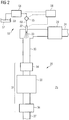
- FIG. 1 illustrates an exemplary embodiment of an engine system 10 suitable for implementing the teachings of the present disclosure.
- the engine system 10 comprises an engine 19 and an aftertreatment module 25. Additionally, as shown in Fig. 1 , the engine system 10 may comprise a turbocharger 12, a supercharger 16, and a cooler 21.
- the engine system 10 comprises a first conduit 11 for directing intake gas, such as atmospheric air, to the turbocharger 12.
- the turbocharger 12 comprises a turbocharger compressor 13.
- the turbocharger compressor 13 is connected to the first conduit 11 and arranged to be driven by a turbine 14 via a shaft 15.
- the engine system 10 further comprises the supercharger 16 for receiving intake gas from the turbocharger compressor 13 via a second conduit 17.
- a supercharger drive arrangement 18 may be provided for selectively driving the supercharger 16.
- the engine 19 is arranged to provide power to the supercharger 16 mechanically via the supercharger drive arrangement 18.
- the engine system 10 further comprises a third conduit 20 for directing the intake gas from the supercharger 16 to the cooler 21.
- the engine system 10 further comprises a supercharger bypass arrangement 22 for selectively allowing intake gas to bypass the supercharger 16.
- the engine 19 may be an internal combustion engine, such as a compression-ignition or spark-ignition engine.
- Fuel such as diesel, gasoline or natural gas, may be selectively provided to engine cylinders in the engine 19 to combust with the intake gas and drive the pistons, thereby rotating a crankshaft and providing an engine output torque and power.
- the byproduct of the combustion process is exhaust gas, which is directed from the engine cylinders along a fifth conduit 23 of the engine system 10 via, for example, an exhaust manifold.
- the exhaust gas may comprise unwanted gaseous emissions or pollutants, such as nitrogen oxides (NOx), particulate matter (such as soot), sulphur oxides, carbon monoxide, unburnt hydrocarbons and/or other organic compounds.
- the fifth conduit 23 directs exhaust gas from the engine 19 to the turbine 14 of the turbocharger 12.
- the engine system 10 further comprises a sixth conduit 24 for directing exhaust gas from the turbine 14 to the exhaust aftertreatment module 25.
- a turbine bypass arrangement 26 may be provided for selectively allowing exhaust gas to bypass the turbine 14.
- the exhaust aftertreatment module 25 receives and treats the exhaust gas to remove pollutants prior to directing the exhaust gas to the atmosphere via a seventh conduit 27.
- the exhaust aftertreatment module 25 comprises a selective catalytic reduction (SCR) system 28 and a diesel oxidation catalyst (DOC) 29.
- the DOC 29 may be arranged to receive exhaust gases from the sixth conduit 24 and may be located upstream of the SCR system 28.
- the SCR system 28 comprises an SCR conduit 30 leading from the DOC 29 to an SCR catalyst arrangement 31.
- the SCR system 28 further comprises an SCR injection system 50.
- the SCR injection system 50 comprises a reductant injector 32, a reductant tank 52, and a pump 54.
- the reductant injector 32 projects into the SCR conduit 30 for selectively injecting reductant fluid 33 into the SCR conduit 30 upstream of the SCR catalyst arrangement 31.
- the reductant tank 52 is configured to store the reductant fluid 33, which may comprise aqueous urea, aqueous ammonia or the like.
- the reductant fluid 33 may be diesel exhaust fluid (DEF), and the DEF may meet the IS022241 standard and comprise from 31.8% to 33.2% urea by weight.
- the pump 54 is configured to pump the reductant fluid 33 from the reductant tank 52 to the reductant injector 32 via a reductant supply line 60.
- the pump 54 may be a diaphragm pump.
- a pressure sensor 55 may be arranged and configured to measure a fluid pressure of the reductant fluid 33 in and/or downstream of the pump 54.
- the pressure sensor 55 is connected to the reductant supply line 60 between the pump 54 and the reductant injector 32.
- the pressure sensor 55 may be integrated into the pump 54 and/or the reductant injector 32
- a control unit 58 is operatively connected to the pump 54, the pressure sensor 55 and the reductant injector 32.
- the control unit 58 is configured to receive pressure data from the pressure sensor 55, to control the pump 54, and to control (actuate) the reductant injector 32.
- the SCR catalyst arrangement 31 comprises, in the direction of exhaust gas flow, a mixer 34, a catalyst substrate 35 and a further oxidation catalyst or AMOx 36.
- the reductant injector 32 may selectively inject the reductant fluid 33, preferably as a liquid, into the stream of exhaust gas to provide a dose of reductant fluid 33 to the SCR catalyst arrangement 31.
- the high exhaust gas temperature may cause the reductant fluid 33 to evaporate, and the resulting combination of gases may reach the catalyst substrate 35.
- the reductant fluid 33 may react with the NOx in the exhaust gas to reduce it to nitrogen and water, which may exit engine system 10 via the seventh conduit 27.
- the catalyst substrate 35 may comprise zeolites, vanadium or the like.
- the engine system 10 may further comprise at least one sensor arranged to sense one or more parameters relating to one or more of the components of the engine system 10 and send signals relating thereto to the control unit 58.
- the engine system 10 may comprise a temperature sensor in communication with the control unit 58 for determining the exhaust gas temperature at the outlet of the engine 19 and/or in the exhaust aftertreatment module 25.
- the control unit 58 may also be in communication with one or more actuators for controlling the operation of the engine 19.
- the control unit 58 may be operable to control the turbocharger 12, the supercharger 16, the rate of fuel injection to the engine 19 and the injection of the reductant fluid 33 by the reductant injector 32.
- the control unit 58 may be a computer and may be operable to store and implement one or more computer programs and may comprise at least one memory, at least one processing unit and at least one communication means.
- the control unit 58 may be an engine control unit (ECU).
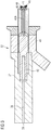
- FIG. 3 An exemplary reductant injector 32 suitable for the engine system 10 is illustrated in FIG. 3 .
- the reductant injector 32 comprises a housing 37 for mounting in the SCR system 28, particularly in the wall of the SCR conduit 30, upstream of the SCR catalyst arrangement 31. Inside the housing 37, a passageway 38 leads from a reductant inlet 39 to a nozzle 40 and injector or nozzle outlet 41. The reductant inlet 39 is in fluid communication with the pump 54 (see Fig. 2 ).
- a valve member 42 including, for example, a needle element 42A is located within the passageway 38.
- the valve member 42 is moveable by an actuator 43 between an open position and a closed position.
- the actuator 43 may be an electrically activated solenoid or the like.
- the actuator 43 is communicatively connected to the control unit 58 such that the control unit 58 controls the movement of the valve member 42 (the needle element 42A) between the open and closed positions.
- the closed position is illustrated in FIG. 3 .
- the control unit 58 controls the injection of reductant fluid 33 in order to control the reduction of NOx by the SCR system 28.
- the reductant fluid 33 may be directed back onto the nozzle 40 after injection by eddy currents in exhaust gases passing through the SCR conduit 30.
- reductant fluid 33 may remain in or enter the reductant injector 32, crystallize and form deposits inside the reductant injector 32. The crystallized deposits may then result in sticking of the valve member 42 (the needle element 42A).
- the control unit 58 controls the actuator 43 to actuate the valve member 42, movement of the valve member 42 may be inhibited or blocked. As a consequence, the supply of reductant may be limited or blocked. This may result in the conversion efficiency of the SCR system 28 being severely reduced and may even lead to failure of the SCR system 28.
- each start of the SCR system 28 triggers one priming operation, and each shutdown of the SCR system 28 triggers one purging operation.
- the term "priming operation” refers to an operation mode of the SCR injection system 50 in which the SCR injection system 50 is made ready for operation.
- the priming operation includes activating the pump 54 to pump reductant from the reductant tank 52 to the reductant injector 32.
- the priming operation further includes actuating the reductant injector 32 to move into the open position.
- the term "purging operation” refers to an operation mode of the SCR injection system 50 in which the SCR injection system 50 is cleaned from remaining reductant in the SCR injection system 50.
- the purging operation includes activating and operating the pump 54 to pump remaining reductant from the reductant injector 32 back to the reductant tank 52.
- the purging operation further includes actuating the reductant injector 32 to move into the open position.
- An end of the purging operation is indicated by a negative pressure building up in the SCR injection system 50, particularly between the pump 54 and the reductant injector 32, because no fluid is left in the reductant injector 32 and the reductant supply line 60.
- FIG. 4 an SCR injection system 50 in accordance with an embodiment of the present disclosure is shown.
- the housing 37 of the reductant injector 32 is mounted to the conduit 30 of the SCR system 28.
- the reductant injector 32 is mounted such that it extends into the conduit 30 in order to inject reductant fluid into the same in accordance with the control by the control unit 58.
- the reductant supply line 60 is connected to the reductant inlet 39 of the reductant injector 32 and connects the same to the pump 54, as described above.
- the reductant supply line 60 includes a portion 60C having an upward slope and extending from the pump 54 (not shown in Fig. 4 ) to a first bent portion 64. From the first bent portion 64, a first supply line portion 60A having a downward slope extends towards the reductant injector 32. In the embodiment shown in Fig. 4 , the supply line portion having the downward slope extends to a second bent portion 62. From the second bent portion 62, a further supply line portion 60B extends upwards to the reductant inlet 39 of the reductant injector 32.
- the first bent portion 64 is disposed above a horizontal datum line D that passes through the reductant inlet 39 of the reductant injector 32.
- the second bent portion 62 is disposed below the datum line D.
- the first bent portion 64 is disposed above the reductant inlet 39 of the reductant injector 32 in the vertical direction
- the second bent portion 62 is disposed below the reductant inlet 39 of the reductant injector 32 in the vertical direction.
- the length of the individual portions of the reductant supply line 60 are configured such that the volume of the compressed air is smaller than the total volume of the reductant supply line 60 between the first bent portion 64 and the reductant inlet 39 of the reductant injector 32. In this manner, it can be assured that the pressurized fluid supplied by the pump 54 reaches the bent portion 64. When the pressurized fluid reaches the bent portion 64, gravity ensures that at least some reductant will flow towards the reductant inlet 39 and into the reductant injector 32 while the corresponding amount of compressed air is pushed out.
- a ratio of the length of the reductant supply line 60 between the first bent portion 64 and the reductant inlet 39 to a total length of the reductant supply line 60 is between around 0.05 and around 0.3, preferably between around 0.1 and around 0.2.
- the ratio will be at least 0.1. It will be readily appreciated that any appropriate ratio can be selected based on the system pressure in order to assure that the reductant fluid 33 reaches the first bent portion 64.
- the second bent portion 62 should be disposed above the datum line D.
- the system is configured such that a distance d from the datum line D to the lowermost portion of the second bent portion 62 is less than the diameter of the reductant supply line 60 at the bent portion 62.
- the datum line D may be defined by the lower edge of the reductant inlet 39.
- the SCR injection system 50 further includes an air release valve 66 arranged in the reductant supply line 60 downstream of the first bent portion 64.
- the air release valve 66 may be arranged in the portion having the downward slope extending from the first bent portion 64 towards the second bent portion 62.
- the air release valve 66 may be arranged in the portion extending from the second bent portion 62 towards the reductant inlet 39 or on the reductant injector 32, if desired.
- the control unit 58 may be configured to open the air release valve 66 at a predetermined time associated with a priming operation of the SCR injection system 50.
- control unit 58 may be configured to open the air release valve 66 prior to or upon initiating the supply of pressurized reductant fluid 33 to reductant supply line 60. It will be readily appreciated that opening of the air release valve 66 allows the air in the reductant supply line 60 to escape from the system, thereby resulting in suppression of the formation of the pocket of compressed air. Accordingly, as will also be readily appreciated, due to the provision of the air release valve 66, the length of the supply line portion 60A may be shortened. This may facilitate the installation of the system in case there is only limited space available in the engine system 10. Of course, the control unit 58 is further configured to close the air release valve 66 prior to the reductant fluid reaching the same in order to avoid leakage of the reductant fluid via the air release valve 66.
- control unit 58 may be configured to close the air release valve 66 after lapse of a predetermined time interval, for example, from initiating the priming operation.
- a predetermined time interval can be determined, for example, by experiment, based on the length of the reductant supply line 60 from the pump 54 to the air release valve 66, the pressure in the system, etc.
- a fluid sensor 69 may be provided in the reductant supply line 60 upstream of the air release valve 66. The fluid sensor 69 may be configured to detect a presence of reductant fluid in the reductant supply line 60.
- the control unit 58 may be operatively connected to the fluid sensor 69, and, upon receiving a corresponding detection result from the fluid sensor 69, close the air release valve 66 before reductant fluid reaches the same. It should be noted that, in other embodiments, the air release valve 66 and/or the fluid sensor 69 may be omitted.
- the second bent portion 62 may be omitted.
- the reductant supply line 60 may only include the first bent portion 64, such that the reductant supply line 60 immediately extends upwards from the reductant inlet 39 of the reductant injector 32 towards the first bent portion 64.
- the remaining configuration may be identical to the configuration shown in Fig. 4 , i.e., the air release valve 66 and the fluid sensor 69 may be provided, if desired. Likewise, the above-mentioned ratios of the respective lengths of the supply line portions also apply.
- the reductant supply line 60 may be arranged such that it extends from the pump 54 towards the reductant inlet 39 of the reductant injector 32 without a portion having a downward slope. It will be readily appreciated that this assures that, during a purge operation, no reductant fluid will flow back towards the reductant injector 32. In this case, however, in order to allow the reductant fluid to reach the reductant inlet 39 during priming of the SCR injection system 50, it is necessary to provide the above-mentioned air release valve 66 either at the reductant inlet 39 or in or on the reductant injector 32.
- control unit 58 may implement the above-described control of the air release valve 66 in order to assure that pressurized reductant fluid can reach the reductant inlet 39, and to close the air release valve 66 at the appropriate timing in order to assure that no reductant fluid leaks via the air release valve 66.
- the fluid sensor 69 may be provided, or that the appropriate timing may be determined in advance based on the system configuration and the system pressure.
- a reductant reservoir 102 may be provided in order to supply reductant fluid to the reductant injector 32 in addition to the reductant fluid supplied via main reductant supply line 60 by the pump 54.
- the reductant reservoir 102 is disposed above the reductant injector 32 and connected to the same by a further reductant supply line 160 that extends upwards from the reductant injector 32.
- a further reductant supply line 160 that extends upwards from the reductant injector 32.
- the reductant supply line 160 is also disposed above the datum line D, i.e., above the reductant injector 32.
- the reductant reservoir 102 does not need to be directly above the reductant injector 32, i.e., it may be offset with respect to the same in the horizontal direction, with an appropriate routing of the reductant supply line 160.
- a supply valve 104 is disposed in the reductant supply line 160 and operatively connected to the control unit 58.
- the control unit 58 is configured to open the supply valve 104, in particular, prior to initiating a priming operation of the SCR injection system 50, i.e., prior to initiating a supply of pressurized reductant fluid 33 by the pump 54.
- reductant fluid 33 in the reductant reservoir 102 will flow towards and into the reductant injector 32 due to gravity. In this manner, any crystallized deposits inside the reductant injector 32 can be dissolved.
- control unit 58 may be configured to open the supply valve 104 for a predetermined time interval, in order to assure that any crystals present inside the reductant injector 32 can be reliably dissolved. It will readily appreciated that the time interval can be determined based on, for example, experiments and the like. In addition, when the priming operation is initiated, the control unit 58 may close the supply valve 104 in order to prevent compressed air from entering the reductant reservoir 102. It will readily be appreciated that an appropriate supply of reductant fluid to the reductant reservoir 102 may be assured in many different ways.
- the reductant reservoir 102 may be fluidly connected to the reductant tank 52, for example, also via the pump 54, and the control unit 58 may be configured to actuate the pump 54 to supply pressurized reductant fluid to reductant reservoir 102 at an appropriate timing, for example, during priming of the system while the supply valve 104 is opened.
- the reductant reservoir 102 may also be fluidly connected to the reductant tank 52 in another manner, for example, by an additional pump or the like.
- the method according to the present disclosure may ensure that crystallized deposits formed in the reductant injector 32 during periods in which reductant fluid 33 is not injected into the SCR system 28 may be reliably dissolved by supplying reductant fluid to the injector.
- the method generally includes a step of supplying a flow of pressurized reductant fluid to a reductant supply line 60.
- the method further comprises directing a flow of reductant fluid upwards to a first bent portion 64 of the reductant supply line 60, and then directing the flow of pressurized reductant fluid downwards from the first bent portion 64 to the reductant injector 32. In this manner, it can be assured that any reductant fluid that has reached the bent portion 64 can flow towards the reductant injector 32 due to gravity.
- the method may further include directing the flow of pressurized reductant fluid upwards to the reductant injector 32 from a second bent portion 62 arranged between the reductant inlet 39 of the reductant injector 32 and the first bent portion 64.
- the methods disclosed herein may include a step of opening an air release valve in order to release air from the reductant supply line 60 during priming of the SCR injection system 50.
- the methods may further comprise a step of closing the air release valve 66 prior to any reductant fluid reaching the same. In this manner, it can also be reliably ensured that reductant fluid reaches the reductant inlet 39 without being blocked by a pocket of compressed air inside reductant supply line 60.
- the methods disclosed herein may comprise the step of providing a reductant reservoir 102 that is disposed above the reductant inlet 39 in the vertical direction.
- the method may include opening of a supply valve 104 disposed in a reductant supply line 160 extending from the reductant injector 32 to the reductant reservoir 102 in order to allow reductant fluid to flow into reductant injector 32 due to gravity.
- the method may include a step of opening the supply valve 104 prior to priming the SCR injection system 50, and closing the same after lapse of a predetermined time interval that is sufficient to ensure that any crystallized deposits inside the reductant injector 32 can be dissolved.
Landscapes
- Chemical & Material Sciences (AREA)
- Engineering & Computer Science (AREA)
- Chemical Kinetics & Catalysis (AREA)
- Health & Medical Sciences (AREA)
- Toxicology (AREA)
- Combustion & Propulsion (AREA)
- Mechanical Engineering (AREA)
- General Engineering & Computer Science (AREA)
- Exhaust Gas After Treatment (AREA)
Priority Applications (2)
| Application Number | Priority Date | Filing Date | Title |
|---|---|---|---|
| EP16203403.7A EP3333386B1 (fr) | 2016-12-12 | 2016-12-12 | Système de dissolution de dépôt d'injecteur et procédé |
| US15/829,191 US10400650B2 (en) | 2016-12-12 | 2017-12-01 | Injector deposit dissolution system and method |
Applications Claiming Priority (1)
| Application Number | Priority Date | Filing Date | Title |
|---|---|---|---|
| EP16203403.7A EP3333386B1 (fr) | 2016-12-12 | 2016-12-12 | Système de dissolution de dépôt d'injecteur et procédé |
Publications (2)
| Publication Number | Publication Date |
|---|---|
| EP3333386A1 true EP3333386A1 (fr) | 2018-06-13 |
| EP3333386B1 EP3333386B1 (fr) | 2019-08-28 |
Family
ID=57542859
Family Applications (1)
| Application Number | Title | Priority Date | Filing Date |
|---|---|---|---|
| EP16203403.7A Active EP3333386B1 (fr) | 2016-12-12 | 2016-12-12 | Système de dissolution de dépôt d'injecteur et procédé |
Country Status (2)
| Country | Link |
|---|---|
| US (1) | US10400650B2 (fr) |
| EP (1) | EP3333386B1 (fr) |
Families Citing this family (2)
| Publication number | Priority date | Publication date | Assignee | Title |
|---|---|---|---|---|
| GB2570140B (en) * | 2018-01-12 | 2020-07-01 | Perkins Engines Co Ltd | Exhaust gas flowhood with treatment fluid injector and variable mounting angle |
| IT201900004639A1 (it) * | 2019-03-28 | 2020-09-28 | Magneti Marelli Spa | Metodo e sistema di iniezione per l'iniezione di acqua in un motore a combustione interna |
Citations (5)
| Publication number | Priority date | Publication date | Assignee | Title |
|---|---|---|---|---|
| WO2006074833A1 (fr) * | 2005-01-17 | 2006-07-20 | Robert Bosch Gmbh | Procede et dispositif pour le post-traitement de gaz d'echappement |
| EP2105592A1 (fr) * | 2008-03-28 | 2009-09-30 | Magneti Marelli Powertrain S.p.A. | Dispositif de montage pour un injecteur dans un système d'échappement de moteur à combustion interne |
| US20110094206A1 (en) * | 2009-10-27 | 2011-04-28 | Cummins Filtration Ip, Inc | Reductant injection and decomposition system |
| EP2631443A1 (fr) * | 2010-10-22 | 2013-08-28 | Bosch Corporation | Dispositif d'alimentation en réducteur ainsi que procédé de commande de celui-ci, et dispositif d'épuration de gaz d'échappement |
| WO2015153350A1 (fr) | 2014-04-04 | 2015-10-08 | Volvo Truck Corporation | Dispositif anti-obstruction pour appareil d'alimentation en fluide d'échappement diesel |
Family Cites Families (10)
| Publication number | Priority date | Publication date | Assignee | Title |
|---|---|---|---|---|
| US6852292B2 (en) | 2002-04-24 | 2005-02-08 | Kleenair Systems, Inc. | Ammonia storage and injection in NOx control |
| DE102006061732A1 (de) | 2006-12-28 | 2008-07-03 | Robert Bosch Gmbh | Vorrichtung zum Dosieren eines flüssigen Reduktionsmittels |
| US7911636B2 (en) * | 2007-07-25 | 2011-03-22 | Eastman Kodak Company | Multi-head press data delivery rate control |
| EP2116700B1 (fr) | 2008-05-09 | 2010-11-10 | Magneti Marelli S.p.A. | Procédé d'injection et dispositif d'injection d'un agent réducteur dans un système d'échappement d'un moteur à combustion interne |
| DE102009011516A1 (de) | 2009-03-06 | 2010-09-16 | Kautex Textron Gmbh & Co. Kg | Betriebsflüssigkeitsbehälter |
| EP2565412A1 (fr) * | 2011-08-29 | 2013-03-06 | Inergy Automotive Systems Research (Société Anonyme) | Système de fourniture de liquide |
| US8800276B2 (en) | 2012-03-14 | 2014-08-12 | Ford Global Technologies, Llc | Mixing system |
| DE102013105712B4 (de) | 2013-06-04 | 2025-08-07 | Schaeffler Technologies AG & Co. KG | Verfahren zum Betrieb einer Vorrichtung zur Förderung einer Flüssigkeit |
| US20150192046A1 (en) | 2015-03-18 | 2015-07-09 | Perkins Engines Company | Injector unit for after-treatment system |
| GB2537598B (en) | 2015-04-13 | 2017-09-13 | Perkins Engines Co Ltd | Method of controlling an engine system |
-
2016
- 2016-12-12 EP EP16203403.7A patent/EP3333386B1/fr active Active
-
2017
- 2017-12-01 US US15/829,191 patent/US10400650B2/en active Active
Patent Citations (5)
| Publication number | Priority date | Publication date | Assignee | Title |
|---|---|---|---|---|
| WO2006074833A1 (fr) * | 2005-01-17 | 2006-07-20 | Robert Bosch Gmbh | Procede et dispositif pour le post-traitement de gaz d'echappement |
| EP2105592A1 (fr) * | 2008-03-28 | 2009-09-30 | Magneti Marelli Powertrain S.p.A. | Dispositif de montage pour un injecteur dans un système d'échappement de moteur à combustion interne |
| US20110094206A1 (en) * | 2009-10-27 | 2011-04-28 | Cummins Filtration Ip, Inc | Reductant injection and decomposition system |
| EP2631443A1 (fr) * | 2010-10-22 | 2013-08-28 | Bosch Corporation | Dispositif d'alimentation en réducteur ainsi que procédé de commande de celui-ci, et dispositif d'épuration de gaz d'échappement |
| WO2015153350A1 (fr) | 2014-04-04 | 2015-10-08 | Volvo Truck Corporation | Dispositif anti-obstruction pour appareil d'alimentation en fluide d'échappement diesel |
Also Published As
| Publication number | Publication date |
|---|---|
| US20180163595A1 (en) | 2018-06-14 |
| US10400650B2 (en) | 2019-09-03 |
| EP3333386B1 (fr) | 2019-08-28 |
Similar Documents
| Publication | Publication Date | Title |
|---|---|---|
| US7908843B2 (en) | Exhaust gas purification device | |
| CN101903624B (zh) | 用于喷射排气处理装置用的流体的设备和方法 | |
| US20110225969A1 (en) | Compressor bypass to exhaust for particulate trap regeneration | |
| US7878183B2 (en) | Apparatus, system, and method to provide air to a doser injector nozzle | |
| US20150204227A1 (en) | Method of Controlling Operation of an Engine Having Both an Exhaust Fluid Recirculation Apparatus and an Exhaust Fluid Treatment Apparatus | |
| US20160298515A1 (en) | Method of Controlling an Engine System | |
| JP2010037979A (ja) | 排気浄化装置 | |
| JP2010019134A (ja) | 内燃機関の排気浄化装置 | |
| US10400650B2 (en) | Injector deposit dissolution system and method | |
| CN108223072B (zh) | 用于选择性催化还原喷射系统的喷射器沉淀检测 | |
| US20150240683A1 (en) | Reductant supply system | |
| EP1826372A1 (fr) | Dispositif antipollution pour l'échappement | |
| CN102162390B (zh) | 一种多次定量精确喷射的选择性催化还原系统 | |
| JP2011144747A (ja) | ディーゼルエンジンの排気浄化装置 | |
| JP5076975B2 (ja) | 内燃機関の排気浄化装置 | |
| EP2460996B1 (fr) | Purificateur d'émission d'échappement de moteur à combustion interne | |
| EP1999348B1 (fr) | Structure de dosage d'échappement de système diesel | |
| EP2273082A1 (fr) | Appareil pour conserver une solution d'urée dans un état liquide pour le traitement d'échappement pour diesel | |
| EP3333388A1 (fr) | Procédé et dispositif de surveillance d'un système d'injection pour un système scr | |
| JP5115734B2 (ja) | 排気浄化装置 | |
| CN105531451B (zh) | 内燃机 | |
| US20230060731A1 (en) | Filter arrangement for a selective catalytic reduction system | |
| JP6281693B2 (ja) | 内燃機関の排気浄化装置 | |
| JP4858724B2 (ja) | 排気浄化装置 | |
| JP2007146750A (ja) | 内燃機関の燃料添加装置 |
Legal Events
| Date | Code | Title | Description |
|---|---|---|---|
| PUAI | Public reference made under article 153(3) epc to a published international application that has entered the european phase |
Free format text: ORIGINAL CODE: 0009012 |
|
| STAA | Information on the status of an ep patent application or granted ep patent |
Free format text: STATUS: THE APPLICATION HAS BEEN PUBLISHED |
|
| AK | Designated contracting states |
Kind code of ref document: A1 Designated state(s): AL AT BE BG CH CY CZ DE DK EE ES FI FR GB GR HR HU IE IS IT LI LT LU LV MC MK MT NL NO PL PT RO RS SE SI SK SM TR |
|
| AX | Request for extension of the european patent |
Extension state: BA ME |
|
| STAA | Information on the status of an ep patent application or granted ep patent |
Free format text: STATUS: REQUEST FOR EXAMINATION WAS MADE |
|
| 17P | Request for examination filed |
Effective date: 20181129 |
|
| RBV | Designated contracting states (corrected) |
Designated state(s): AL AT BE BG CH CY CZ DE DK EE ES FI FR GB GR HR HU IE IS IT LI LT LU LV MC MK MT NL NO PL PT RO RS SE SI SK SM TR |
|
| GRAP | Despatch of communication of intention to grant a patent |
Free format text: ORIGINAL CODE: EPIDOSNIGR1 |
|
| STAA | Information on the status of an ep patent application or granted ep patent |
Free format text: STATUS: GRANT OF PATENT IS INTENDED |
|
| INTG | Intention to grant announced |
Effective date: 20190312 |
|
| GRAS | Grant fee paid |
Free format text: ORIGINAL CODE: EPIDOSNIGR3 |
|
| GRAA | (expected) grant |
Free format text: ORIGINAL CODE: 0009210 |
|
| STAA | Information on the status of an ep patent application or granted ep patent |
Free format text: STATUS: THE PATENT HAS BEEN GRANTED |
|
| AK | Designated contracting states |
Kind code of ref document: B1 Designated state(s): AL AT BE BG CH CY CZ DE DK EE ES FI FR GB GR HR HU IE IS IT LI LT LU LV MC MK MT NL NO PL PT RO RS SE SI SK SM TR |
|
| REG | Reference to a national code |
Ref country code: GB Ref legal event code: FG4D |
|
| REG | Reference to a national code |
Ref country code: CH Ref legal event code: EP |
|
| REG | Reference to a national code |
Ref country code: AT Ref legal event code: REF Ref document number: 1172673 Country of ref document: AT Kind code of ref document: T Effective date: 20190915 |
|
| REG | Reference to a national code |
Ref country code: IE Ref legal event code: FG4D |
|
| REG | Reference to a national code |
Ref country code: DE Ref legal event code: R096 Ref document number: 602016019332 Country of ref document: DE |
|
| REG | Reference to a national code |
Ref country code: NL Ref legal event code: MP Effective date: 20190828 |
|
| REG | Reference to a national code |
Ref country code: LT Ref legal event code: MG4D |
|
| PG25 | Lapsed in a contracting state [announced via postgrant information from national office to epo] |
Ref country code: SE Free format text: LAPSE BECAUSE OF FAILURE TO SUBMIT A TRANSLATION OF THE DESCRIPTION OR TO PAY THE FEE WITHIN THE PRESCRIBED TIME-LIMIT Effective date: 20190828 Ref country code: HR Free format text: LAPSE BECAUSE OF FAILURE TO SUBMIT A TRANSLATION OF THE DESCRIPTION OR TO PAY THE FEE WITHIN THE PRESCRIBED TIME-LIMIT Effective date: 20190828 Ref country code: PT Free format text: LAPSE BECAUSE OF FAILURE TO SUBMIT A TRANSLATION OF THE DESCRIPTION OR TO PAY THE FEE WITHIN THE PRESCRIBED TIME-LIMIT Effective date: 20191230 Ref country code: FI Free format text: LAPSE BECAUSE OF FAILURE TO SUBMIT A TRANSLATION OF THE DESCRIPTION OR TO PAY THE FEE WITHIN THE PRESCRIBED TIME-LIMIT Effective date: 20190828 Ref country code: LT Free format text: LAPSE BECAUSE OF FAILURE TO SUBMIT A TRANSLATION OF THE DESCRIPTION OR TO PAY THE FEE WITHIN THE PRESCRIBED TIME-LIMIT Effective date: 20190828 Ref country code: NL Free format text: LAPSE BECAUSE OF FAILURE TO SUBMIT A TRANSLATION OF THE DESCRIPTION OR TO PAY THE FEE WITHIN THE PRESCRIBED TIME-LIMIT Effective date: 20190828 Ref country code: BG Free format text: LAPSE BECAUSE OF FAILURE TO SUBMIT A TRANSLATION OF THE DESCRIPTION OR TO PAY THE FEE WITHIN THE PRESCRIBED TIME-LIMIT Effective date: 20191128 Ref country code: NO Free format text: LAPSE BECAUSE OF FAILURE TO SUBMIT A TRANSLATION OF THE DESCRIPTION OR TO PAY THE FEE WITHIN THE PRESCRIBED TIME-LIMIT Effective date: 20191128 |
|
| PG25 | Lapsed in a contracting state [announced via postgrant information from national office to epo] |
Ref country code: AL Free format text: LAPSE BECAUSE OF FAILURE TO SUBMIT A TRANSLATION OF THE DESCRIPTION OR TO PAY THE FEE WITHIN THE PRESCRIBED TIME-LIMIT Effective date: 20190828 Ref country code: ES Free format text: LAPSE BECAUSE OF FAILURE TO SUBMIT A TRANSLATION OF THE DESCRIPTION OR TO PAY THE FEE WITHIN THE PRESCRIBED TIME-LIMIT Effective date: 20190828 Ref country code: IS Free format text: LAPSE BECAUSE OF FAILURE TO SUBMIT A TRANSLATION OF THE DESCRIPTION OR TO PAY THE FEE WITHIN THE PRESCRIBED TIME-LIMIT Effective date: 20191228 Ref country code: LV Free format text: LAPSE BECAUSE OF FAILURE TO SUBMIT A TRANSLATION OF THE DESCRIPTION OR TO PAY THE FEE WITHIN THE PRESCRIBED TIME-LIMIT Effective date: 20190828 Ref country code: RS Free format text: LAPSE BECAUSE OF FAILURE TO SUBMIT A TRANSLATION OF THE DESCRIPTION OR TO PAY THE FEE WITHIN THE PRESCRIBED TIME-LIMIT Effective date: 20190828 Ref country code: GR Free format text: LAPSE BECAUSE OF FAILURE TO SUBMIT A TRANSLATION OF THE DESCRIPTION OR TO PAY THE FEE WITHIN THE PRESCRIBED TIME-LIMIT Effective date: 20191129 |
|
| REG | Reference to a national code |
Ref country code: AT Ref legal event code: MK05 Ref document number: 1172673 Country of ref document: AT Kind code of ref document: T Effective date: 20190828 |
|
| PG25 | Lapsed in a contracting state [announced via postgrant information from national office to epo] |
Ref country code: TR Free format text: LAPSE BECAUSE OF FAILURE TO SUBMIT A TRANSLATION OF THE DESCRIPTION OR TO PAY THE FEE WITHIN THE PRESCRIBED TIME-LIMIT Effective date: 20190828 |
|
| PG25 | Lapsed in a contracting state [announced via postgrant information from national office to epo] |
Ref country code: IT Free format text: LAPSE BECAUSE OF FAILURE TO SUBMIT A TRANSLATION OF THE DESCRIPTION OR TO PAY THE FEE WITHIN THE PRESCRIBED TIME-LIMIT Effective date: 20190828 Ref country code: RO Free format text: LAPSE BECAUSE OF FAILURE TO SUBMIT A TRANSLATION OF THE DESCRIPTION OR TO PAY THE FEE WITHIN THE PRESCRIBED TIME-LIMIT Effective date: 20190828 Ref country code: DK Free format text: LAPSE BECAUSE OF FAILURE TO SUBMIT A TRANSLATION OF THE DESCRIPTION OR TO PAY THE FEE WITHIN THE PRESCRIBED TIME-LIMIT Effective date: 20190828 Ref country code: AT Free format text: LAPSE BECAUSE OF FAILURE TO SUBMIT A TRANSLATION OF THE DESCRIPTION OR TO PAY THE FEE WITHIN THE PRESCRIBED TIME-LIMIT Effective date: 20190828 Ref country code: EE Free format text: LAPSE BECAUSE OF FAILURE TO SUBMIT A TRANSLATION OF THE DESCRIPTION OR TO PAY THE FEE WITHIN THE PRESCRIBED TIME-LIMIT Effective date: 20190828 Ref country code: PL Free format text: LAPSE BECAUSE OF FAILURE TO SUBMIT A TRANSLATION OF THE DESCRIPTION OR TO PAY THE FEE WITHIN THE PRESCRIBED TIME-LIMIT Effective date: 20190828 |
|
| PG25 | Lapsed in a contracting state [announced via postgrant information from national office to epo] |
Ref country code: IS Free format text: LAPSE BECAUSE OF FAILURE TO SUBMIT A TRANSLATION OF THE DESCRIPTION OR TO PAY THE FEE WITHIN THE PRESCRIBED TIME-LIMIT Effective date: 20200224 Ref country code: SK Free format text: LAPSE BECAUSE OF FAILURE TO SUBMIT A TRANSLATION OF THE DESCRIPTION OR TO PAY THE FEE WITHIN THE PRESCRIBED TIME-LIMIT Effective date: 20190828 Ref country code: SM Free format text: LAPSE BECAUSE OF FAILURE TO SUBMIT A TRANSLATION OF THE DESCRIPTION OR TO PAY THE FEE WITHIN THE PRESCRIBED TIME-LIMIT Effective date: 20190828 Ref country code: CZ Free format text: LAPSE BECAUSE OF FAILURE TO SUBMIT A TRANSLATION OF THE DESCRIPTION OR TO PAY THE FEE WITHIN THE PRESCRIBED TIME-LIMIT Effective date: 20190828 |
|
| REG | Reference to a national code |
Ref country code: DE Ref legal event code: R097 Ref document number: 602016019332 Country of ref document: DE |
|
| PLBE | No opposition filed within time limit |
Free format text: ORIGINAL CODE: 0009261 |
|
| STAA | Information on the status of an ep patent application or granted ep patent |
Free format text: STATUS: NO OPPOSITION FILED WITHIN TIME LIMIT |
|
| PG2D | Information on lapse in contracting state deleted |
Ref country code: IS |
|
| REG | Reference to a national code |
Ref country code: CH Ref legal event code: PL |
|
| 26N | No opposition filed |
Effective date: 20200603 |
|
| REG | Reference to a national code |
Ref country code: BE Ref legal event code: MM Effective date: 20191231 |
|
| PG25 | Lapsed in a contracting state [announced via postgrant information from national office to epo] |
Ref country code: MC Free format text: LAPSE BECAUSE OF FAILURE TO SUBMIT A TRANSLATION OF THE DESCRIPTION OR TO PAY THE FEE WITHIN THE PRESCRIBED TIME-LIMIT Effective date: 20190828 Ref country code: SI Free format text: LAPSE BECAUSE OF FAILURE TO SUBMIT A TRANSLATION OF THE DESCRIPTION OR TO PAY THE FEE WITHIN THE PRESCRIBED TIME-LIMIT Effective date: 20190828 |
|
| PG25 | Lapsed in a contracting state [announced via postgrant information from national office to epo] |
Ref country code: IE Free format text: LAPSE BECAUSE OF NON-PAYMENT OF DUE FEES Effective date: 20191212 Ref country code: FR Free format text: LAPSE BECAUSE OF NON-PAYMENT OF DUE FEES Effective date: 20191231 Ref country code: LU Free format text: LAPSE BECAUSE OF NON-PAYMENT OF DUE FEES Effective date: 20191212 |
|
| PG25 | Lapsed in a contracting state [announced via postgrant information from national office to epo] |
Ref country code: BE Free format text: LAPSE BECAUSE OF NON-PAYMENT OF DUE FEES Effective date: 20191231 Ref country code: CH Free format text: LAPSE BECAUSE OF NON-PAYMENT OF DUE FEES Effective date: 20191231 Ref country code: LI Free format text: LAPSE BECAUSE OF NON-PAYMENT OF DUE FEES Effective date: 20191231 |
|
| PG25 | Lapsed in a contracting state [announced via postgrant information from national office to epo] |
Ref country code: CY Free format text: LAPSE BECAUSE OF FAILURE TO SUBMIT A TRANSLATION OF THE DESCRIPTION OR TO PAY THE FEE WITHIN THE PRESCRIBED TIME-LIMIT Effective date: 20190828 |
|
| PG25 | Lapsed in a contracting state [announced via postgrant information from national office to epo] |
Ref country code: HU Free format text: LAPSE BECAUSE OF FAILURE TO SUBMIT A TRANSLATION OF THE DESCRIPTION OR TO PAY THE FEE WITHIN THE PRESCRIBED TIME-LIMIT; INVALID AB INITIO Effective date: 20161212 Ref country code: MT Free format text: LAPSE BECAUSE OF FAILURE TO SUBMIT A TRANSLATION OF THE DESCRIPTION OR TO PAY THE FEE WITHIN THE PRESCRIBED TIME-LIMIT Effective date: 20190828 |
|
| PG25 | Lapsed in a contracting state [announced via postgrant information from national office to epo] |
Ref country code: MK Free format text: LAPSE BECAUSE OF FAILURE TO SUBMIT A TRANSLATION OF THE DESCRIPTION OR TO PAY THE FEE WITHIN THE PRESCRIBED TIME-LIMIT Effective date: 20190828 |
|
| P01 | Opt-out of the competence of the unified patent court (upc) registered |
Effective date: 20230517 |
|
| PGFP | Annual fee paid to national office [announced via postgrant information from national office to epo] |
Ref country code: DE Payment date: 20251126 Year of fee payment: 10 |
|
| PGFP | Annual fee paid to national office [announced via postgrant information from national office to epo] |
Ref country code: GB Payment date: 20251120 Year of fee payment: 10 |