EP3333302B1 - Wasch- und/oder trocknungsmaschine - Google Patents
Wasch- und/oder trocknungsmaschine Download PDFInfo
- Publication number
- EP3333302B1 EP3333302B1 EP16203519.0A EP16203519A EP3333302B1 EP 3333302 B1 EP3333302 B1 EP 3333302B1 EP 16203519 A EP16203519 A EP 16203519A EP 3333302 B1 EP3333302 B1 EP 3333302B1
- Authority
- EP
- European Patent Office
- Prior art keywords
- toothed profile
- machine
- toothed
- connecting device
- frame
- Prior art date
- Legal status (The legal status is an assumption and is not a legal conclusion. Google has not performed a legal analysis and makes no representation as to the accuracy of the status listed.)
- Active
Links
Images




Classifications
-
- D—TEXTILES; PAPER
- D06—TREATMENT OF TEXTILES OR THE LIKE; LAUNDERING; FLEXIBLE MATERIALS NOT OTHERWISE PROVIDED FOR
- D06F—LAUNDERING, DRYING, IRONING, PRESSING OR FOLDING TEXTILE ARTICLES
- D06F37/00—Details specific to washing machines covered by groups D06F21/00 - D06F25/00
- D06F37/26—Casings; Tubs
- D06F37/266—Gaskets mounted between tub and casing around the loading opening
Definitions
- the present invention relates to a washing and/or drying machine comprising a housing having an access opening closed by a door, a wash tub having an opening and enclosing a rotating drum, a sleeve disposed between the access opening of the housing and the opening built into the wash tub.
- the present invention relates to a top-loading washing and/or drying machine comprising a housing having a top access opening, a tub mounted in the cabinet with a top opening, a perforated drum rotatably mounted within said tub about a horizontal axis and having an aperture on its cylindrical side.
- the present invention refers to the clamp or clamps configured to fasten the sleeve to the housing and/or to the wash tub.
- washing and/or drying machines include a support cabinet, on which a washing tub is mounted, inside which rotates a drum, wherein the garments to be washed are placed.
- the tub has an opening through which the access to the drum is possible and clothes can be placed inside the drum.
- An opening closed by a door is also present on the cabinet or housing.
- EP1793029 discloses a machine for washing and/or drying clothes of top loading horizontal axis type, comprising a housing with an access opening closed by a door, a tub that has an opening and surrounds a rotary drum, and a sleeve between the access opening and the tub opening, comprises a sleeve with a fastener, one side of which is inserted into a U-shaped part of the sleeve that fits into a groove in the tub.
- the sleeve is usually made of flexible rubber or the like, it is subject to aging and deterioration and sometimes it should be replaced.
- the fastener allows to mount and dismantle said sleeve.
- Document KR 2000 0033178 A discloses a tub gasket clamp of a drum washing machine, wherein the clamp body ends are fastening portions provided with coupling holes for passing through a fastening screw.
- Another object of the present invention is to provide a clamping framework which allows the sleeve to be mounted and dismantled quickly and easily.
- Another object of the present invention is to provide a clamping framework which allows the sleeve to be mounted safely into the washing and/or drying machine and assure the correct and steady position of said sleeve during operation of the machine.
- a clamping framework comprising two frames which are releasably connected one to the other through a toothed connecting device, wherein said connecting device can be unlocked by exerting a force on the first frame and/or the second frame along a direction substantially perpendicular to a surface on which the clamping framework lies.
- present invention relates to a washing and/or drying machine as defined in independent claim 1.
- Preferred embodiments of the present invention are the subject-matter of the dependent claims.
- the Applicant verified that the position of the toothed profiles allows to move away the first toothed profile from the second toothed profile in order to disengage/unlock the connecting device in easy and rapid way. Therefore, the invention allows to disconnect the first frame from the second frame and to remove the clamping framework quickly and easily.
- the present invention in at least one of the aforesaid aspects, can have one or more of the preferred characteristics that are described hereinbelow.
- the first toothed profile lies on a face of the elongated element substantially parallel to the surface on which the clamping framework lies.
- the second toothed profile is placed inside said seat and lies substantially parallel to the surface on which the clamping framework lies.
- the seat presents a front opening to allow insertion of the elongated element into said seat and engagement of the first toothed profile with the second toothed profile.
- the second part comprises a C-shaped body provided with a first tab, a second tab and a connecting portion delimiting said seat.
- said seat opens laterally towards the outside of the clamping framework.
- the connecting portion is configured to be inserted into the slot to engage the first and second toothed profiles.
- the first tab presents an inner surface comprising the second toothed profile facing the first toothed profile of the elongated element.
- the second tab presents an inner substantially smooth surface configured to come into contact with a surface of the elongated element opposite the first toothed profile.
- first tab and/or the second tab are flexible so to allow disengagement of the first toothed profile from the second toothed profile by exerting a force on the first part and/or the second part along a direction substantially perpendicular to the surface on which the clamping framework lies.
- flexible means that the first tab and/or the second tab may be deformed during assembling and disassembling of the connecting device when subjected to the forces needed to engage/disengage the toothed profiles. When the first tab and/or the second tab are not subject to said forces, they are able to recover their un-deformed configurations.
- first toothed profile extends only in part on the respective surface of the elongated element.
- second toothed profile extends only in part on the respective surface of the first tab.
- the second toothed profile is shorter than the inner surface.
- the second part comprises a protrusion placed on the opposite side of the C-shaped body with respect to the front opening.
- a rear portion of the elongated element and said protrusion are configured to be clamped by an assembly tool to insert the elongated element in the seat through the front opening when mounting the clamping framework.
- the teeth of the first toothed profile are placed one after the other along a first direction.
- the teeth of the second toothed profile are placed one after the other along a second direction.
- engagement of the first toothed profile with the second toothed profile is performed by aligning the first and second directions and making the first toothed profile and the second toothed profile slide one over the other along said first and second common directions.
- the first U-shaped frame and the second U-shaped frame are identical and each comprises one first part placed on a first end and one second part placed on a second end.
- each of the first and second frames is made of plastic, preferably molded in one piece.
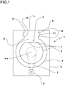
- FIG. 1 designates a top loading horizontal drum washing machine.
- a perforated rotating drum 2 of the machine 1 comprises a stainless steel cylindrical wrapper provided with a rectangular drum aperture 3 provided doors 4.
- the drum 2 is rotating within a plastic tub T mounted, with the interposition of known dampers, within a housing or cabinet C.
- Such cabinet C is provided with a lid L for closing an access opening 5 towards the drum 2.
- the tub T is fixed to the cabinet C and the drum 2 is mounted within said cabinet C and within the tub T to rotate about a horizontal axis X-X by means of a motor 6 mounted in the cabinet C and connected to the drum 2 through a pulley 7.
- the tub T has a tub opening 8 facing the access opening 5.
- the access opening 5 in the housing C is delimited by a first wall 9 protruding downwards in the cabinet towards the tub T.
- the tub opening 8 is delimited by a second wall 10 protruding upwards towards the access opening 5.
- a bellow sleeve 11 is connected to the first wall 9 and to the second wall 10 to delimit a tubular conduit extending between the access opening 5 and the tub opening 8.
- a first end of the bellow sleeve 11 surrounds the first wall 9 and a second end of the bellow sleeve 11 surrounds the second wall 10.
- a clamping framework 12 surrounds the first end of the bellow sleeve 11 to hold said first end onto the first wall 9.
- a further clamping framework 12 surrounds the second end of the bellow sleeve 11 to hold said second end onto the second wall 10.
- the ends of the bellow sleeve 11 and the respective clamping framework 12 may be positioned in a respective groove, not shown, made in the first wall 9 and/or in the second wall 10.
- the two clamping frameworks 12 have the same structure shown in figures 3 , 3A , 4 and 4A and detailed in the following passages.
- the access opening 5, the tub opening 8 and the clamping framework 12 present a substantially rectangular shape but other shapes may be adopted.
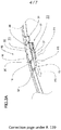
- the clamping framework 12 is preferably made of plastic and comprises a first U shaped frame 13 and a second U shaped frame 14. Each U shaped frame is a sort of rod shaped element profiled like a U.
- One end of the first U shaped frame 13 comprises a first part 15 of a connecting device 16.
- the other end of the first U shaped frame 13 comprises a second part 17 of another connecting device 16.
- One end of the second U shaped frame 14 comprises a first part 15 of the other connecting device 16.
- the other end of the second U shaped frame 14 comprises the second part 17 of the connecting device 16.
- the first part 15 of the first U shaped frame 13 is configured to be releasably connected to the second part 17 of the second U shaped frame 14 and the first part 15 of the second U shaped frame 14 is configured to be releasably connected to the second part 17 of the first U shaped frame 13 as shown in figures 3 and 4 .
- the assembly comprising a first part 15 and a second part 17 is a single connecting device 16 and will be detailed in the following passages.
- the first part 15 comprises an elongated element 18 attached, like an appendix, to a side of an end 19 of the frame 13, 14 and running parallel to said end 19. Said elongated element 18 and said end 19 delimit between them a slot 20.
- the elongated element 18 protrudes beyond said end 19 and presents a first and a second opposite faces lying substantially parallel to a surface onto which the clamping framework 12 lies.
- the upper face is flat and the lower face is provided with a first toothed profile 21.
- the first toothed profile 21 comprises a plurality of teeth placed in succession one after the other along a first direction Y. Each tooth presents a crest extending substantially perpendicular to the longitudinal extension of the elongated element 18.
- the end 19 is tapered and beveled.
- the second part 17 comprises a C-shaped body provided with a first tab 22, a second tab 23 and a portion 24 connecting the first tab 22 to the second tab 23.
- the connecting portion 23 is attached to an end 25 of the other frame 14, 13.
- the first tab 22, the second tab 23 and the connecting portion 24 delimit a seat 26 which opens laterally towards the outside of the clamping framework 12.
- Said seat 26 further presents a front opening 27 and a rear opening 28.
- the end 25 of the other frame 14, 13 is beveled to mate with the end 19 of the frame 13, 14.
- the first lower tab 22 presents an inner surface comprising a second toothed profile 29 facing upwards.
- the second toothed profile 29 is shorter than the first toothed profile 21 and comprises a plurality of teeth placed in succession one after the other along a second direction Z.
- Each tooth presents a crest extending substantially perpendicular to the longitudinal extension of the seat 26.
- the second upper tab 23 further presents an inner substantially smooth surface 30.
- the first tab 22 and/or the second tab 23 are flexible by exerting a force along a direction substantially perpendicular to the surface on which the clamping framework 12 lies.
- a protrusion 31 is placed on the frame 14, 13 close to the C-shaped body. Such protrusion 31 is spaced from the rear opening 28 and faces said rear opening 28. Further, the elongated element 18 presents a rear portion 32 configured to be clamped by an assembly tool together with the protrusion 31 as detailed in the following passages.
- the teeth of said first and second toothed profiles 21, 29 project substantially perpendicular to a surface S on which the clamping framework 12 lies (see figure 3 ).
- the first and second U shaped frames 13, 14 are assembled by inserting each elongated element 18 in the respective seat 26 through the front opening 27 of the C-shaped body along the common first and second direction Y, Z (arrows F1, F2). Simultaneously, the connecting portion 24 enters the slot 20.
- This movement may be performed manually or by means of a clamping tool, like a wrench, which grasps and brings the first part 15 towards the second part 17.
- the clamping tool acts on the rear portion 32 and the protrusion 31.
- the first toothed profile 21 faces the second toothed profile 29 and slides on said second toothed profile 29 thanks to the flexibility of the tabs 22, 23, until the bevels of the ends 19, 25 come into mutual contact.
- the inner substantially smooth surface 30 of the second tab 23 slides freely on the upper surface of the elongated element 18.
- the clamping framework 12 If the clamping framework 12 is to be disassembled, a force on the elongated element 18 along arrow F5 is exerted while the C-shaped body is held in place.
- the first tab 22 bends/deforms allowing the teeth of the first toothed profile 21 to disengage from the teeth of the second toothed profile 29. Then the elongated element 18 may be extracted along arrow F3 from the C-shaped body.
- F5 is the direction perpendicular to the surface on which the clamping framework 12 lies.
- clamping framework described herein by way of example may be subject to many possible variations without departing from the novelty spirit of the inventive idea.
- shape of the framework may be circular or elliptic.
Landscapes
- Engineering & Computer Science (AREA)
- Textile Engineering (AREA)
- Main Body Construction Of Washing Machines And Laundry Dryers (AREA)
- Clamps And Clips (AREA)
Claims (13)
- Wasch- und/oder Trockenmaschine, umfassend:ein Gehäuse (C) mit einer Zugangsöffnung (5);eine rotierende Trommel (2);eine Wanne (T) mit einer Wannenöffnung (8) und die rotierende Trommel (2) umgebend;eine Muffe (11), die zwischen der Zugangsöffnung (5) des Gehäuses (C) und der Wannenöffnung (8) der Wanne (T) angeordnet ist;mindestens einen Spannrahmen (12), der mindestens ein Ende der Muffe (11) umgibt, um die Muffe (11) an dem Gehäuse (C) und/oder der Wanne (T) zu befestigen;wobei der mindestens eine Spannrahmen (12) einen ersten U-förmigen Rahmen (13) umfasst und einen zweiten U-förmigen Rahmen (14) und eine erste Verbindungsvorrichtung (16) und eine zweite Verbindungsvorrichtung (16), wobei jede der ersten und der zweiten Verbindungsvorrichtung (16) konfiguriert ist, den ersten Rahmen (13) lösbar mit dem zweiten Rahmen (14) zu verbinden, wobei jede von der ersten und der zweiten Verbindungsvorrichtung (16) ein erstes Teil (15) umfasst, das mit einem ersten Zahnprofil (21) bereitgestellt wird, das in ein zweites Teil (17) greift, das mit einem zweiten Zahnprofil (29) bereitgestellt wird,wobei ein Ende des ersten U-förmigen Rahmens (13) das erste Teil (15) der ersten Verbindungsvorrichtung (16) umfasst, das andere Ende des ersten U-förmigen Rahmens (13) das zweite Teil (17) der zweiten Verbindungsvorrichtung (16) umfasst;wobei ein Ende des zweiten U-förmigen Rahmens (14) ein erstes Teil (15) der zweiten Verbindungsvorrichtung (16) umfasst, das andere Ende des zweiten U-förmigen Rahmens (14) das zweite Teil (17) der ersten Verbindungsvorrichtung (16) umfasst;wobei jedes erste Teil (15) ein längliches Element (18) umfasst, das mit dem ersten Zahnprofil (21) bereitgestellt wird und zusammen mit dem jeweiligen Ende (19) des ersten Rahmens (13) oder des zweiten Rahmens (4) einen Schlitz (20) begrenzt;wobei jedes zweite Teil (17) einen Sitz (26) aufweist, der an dem jeweiligen Ende (25) des zweiten Rahmens (14) oder des ersten Rahmens (13) platziert ist und konfiguriert ist, das längliche Element (18) aufzunehmen;wobei die Zähne des ersten und des zweiten Zahnprofils (21, 29) im Wesentlichen senkrecht zu einer Fläche (S) projizieren, auf der der Spannrahmen (12) liegt.
- Maschine nach Anspruch 1, wobei das erste Zahnprofil (21) auf einer Fläche des länglichen Elements (18) im Wesentlichen parallel zu der Fläche (S) liegt, auf der der Spannrahmen (12) liegt.
- Maschine nach Anspruch 1 oder 2, wobei das zweite Zahnprofil (29) innerhalb des Sitzes (26) platziert ist und im Wesentlichen parallel zu der Fläche (S) liegt, auf der der Spannrahmen (12) liegt.
- Maschine nach Anspruch 3, wobei der Sitz (26) eine vordere Öffnung (27) aufweist, um Einführen des länglichen Elements (18) in den Sitz (26) und Eingriff des ersten Zahnprofils (21) in das zweite Zahnprofil (29) zu ermöglichen.
- Maschine nach einem der vorstehenden Ansprüche, wobei das zweite Teil (17) einen C-förmigen Körper umfasst, der mit einer ersten Lasche (22), einer zweiten Lasche (23) und einem Verbindungsabschnitt (24), den Sitz (26) begrenzend, bereitgestellt wird.
- Maschine nach Anspruch 5, wobei der Sitz (26) lateral in Richtung der Außenseite des Spannrahmens (12) öffnet.
- Maschine nach Anspruch 5 oder 6, wobei der Verbindungsabschnitt (24) konfiguriert ist, in den Schlitz (20) eingeführt zu werden, um in das erste und das zweite Zahnprofil (21, 29) zu greifen.
- Maschine nach Anspruch 5, 6 oder 7, wobei, wenn die Verbindungsvorrichtung (16) montiert ist, die erste Lasche (22) eine innere Fläche aufweist, die das zweite Zahnprofil (29) aufweist, das dem ersten Zahnprofil (21) des länglichen Elements (18) zugewandt ist; wobei die zweite Lasche (23) eine innere, im Wesentlichen glatte Fläche (30) aufweist, die konfiguriert ist, in Kontakt mit einer Fläche des länglichen Elements (18) dem ersten Zahnprofil (21) gegenüber zu kommen.
- Maschine nach einem der Ansprüche 5 bis 8, wobei die erste Lasche (22) und/oder die zweite Lasche (23) flexibel sind, um Lösen des ersten Zahnprofils (21) von dem zweiten Zahnprofil (29) durch Ausüben einer Kraft auf das erste Teil (15) und/oder das zweite Teil (17) entlang einer Richtung im Wesentlichen senkrecht zu der Fläche (S), auf der der Spannrahmen (12) liegt, zu ermöglichen.
- Maschine nach Anspruch 8, wobei das zweite Zahnprofil (29) kürzer als die innere Fläche ist, um ein leichtes Lösen der Zahnprofile (21, 29) zu ermöglichen.
- Maschine nach einem der Ansprüche 5 bis 10, wobei das zweite Teil (17) einen Vorsprung (31) umfasst, der auf der gegenüberliegenden Seite des C-förmigen Körpers relativ zu der vorderen Öffnung (27) platziert ist, wobei ein hinterer Abschnitt (32) des länglichen Elements (18) und der Vorsprung (31) konfiguriert sind, von einem Montagewerkzeug geklemmt zu werden, um das längliche Element (18) in den Sitz (26) durch die vordere Öffnung (27) einzuführen, wenn der Spannrahmen (12) montiert wird.
- Maschine nach einem der vorstehenden Ansprüche, wobei die Zähne des ersten Zahnprofils (21) einer nach dem anderen entlang einer ersten Richtung (Y) platziert sind; wobei die Zähne des zweiten Zahnprofils (29) einer nach dem anderen entlang einer zweiten Richtung (Z) platziert sind; wobei Eingriff des ersten Zahnprofils (21) in das zweite Zahnprofil (29) durch Ausrichten der ersten und zweiten Richtungen (Y, Z) durchgeführt wird und durch übereinander Gleiten lassen des ersten Zahnprofils (21) und des zweiten Zahnprofils (29) über die andere entlang der ersten und zweiten gemeinsamen Richtungen (Y, Z).
- Maschine nach einem der vorstehenden Ansprüche, wobei der erste U-förmige Rahmen (13) und der zweite U-förmige Rahmen (14) identisch sind und jeweils ein erstes Teil (15) umfassen, das auf einem ersten Ende platziert ist, und ein zweites Teils (17), das auf einem zweiten Ende platziert ist.
Priority Applications (1)
| Application Number | Priority Date | Filing Date | Title |
|---|---|---|---|
| EP16203519.0A EP3333302B1 (de) | 2016-12-12 | 2016-12-12 | Wasch- und/oder trocknungsmaschine |
Applications Claiming Priority (1)
| Application Number | Priority Date | Filing Date | Title |
|---|---|---|---|
| EP16203519.0A EP3333302B1 (de) | 2016-12-12 | 2016-12-12 | Wasch- und/oder trocknungsmaschine |
Publications (2)
| Publication Number | Publication Date |
|---|---|
| EP3333302A1 EP3333302A1 (de) | 2018-06-13 |
| EP3333302B1 true EP3333302B1 (de) | 2020-06-10 |
Family
ID=57542897
Family Applications (1)
| Application Number | Title | Priority Date | Filing Date |
|---|---|---|---|
| EP16203519.0A Active EP3333302B1 (de) | 2016-12-12 | 2016-12-12 | Wasch- und/oder trocknungsmaschine |
Country Status (1)
| Country | Link |
|---|---|
| EP (1) | EP3333302B1 (de) |
Families Citing this family (1)
| Publication number | Priority date | Publication date | Assignee | Title |
|---|---|---|---|---|
| CN111733571A (zh) * | 2019-03-19 | 2020-10-02 | 青岛海尔滚筒洗衣机有限公司 | 一种洗衣机观察窗垫紧固圈及洗衣机 |
Family Cites Families (5)
| Publication number | Priority date | Publication date | Assignee | Title |
|---|---|---|---|---|
| FR2296048A1 (fr) * | 1974-12-24 | 1976-07-23 | Thomson Brandt | Machine a laver le linge a tambour |
| IT8434064V0 (it) * | 1984-10-22 | 1984-10-22 | Zanussi Elettrodomestici | Guarnizione, in particolare per apparecchiature elettrodomestiche. |
| KR100546577B1 (ko) * | 1998-11-20 | 2006-03-23 | 엘지전자 주식회사 | 드럼세탁기의 터브 가스켓 클램프 |
| EP1746321A1 (de) * | 2005-07-22 | 2007-01-24 | IMET S.r.l. | Befestigungseinrichtung für zylindrische Elemente, insbesondere Rohrleitungen und Kabel |
| FR2893955B1 (fr) | 2005-11-30 | 2007-12-28 | Brandt Ind Sas | Machine a laver et ou secher le linge munie d'une manchette de liaison cuve carrosserie et procede d'assemblage de ladite manchette |
-
2016
- 2016-12-12 EP EP16203519.0A patent/EP3333302B1/de active Active
Non-Patent Citations (1)
| Title |
|---|
| None * |
Also Published As
| Publication number | Publication date |
|---|---|
| EP3333302A1 (de) | 2018-06-13 |
Similar Documents
| Publication | Publication Date | Title |
|---|---|---|
| EP2861792B1 (de) | Wäschebehandlungsvorrichtung mit türanordnung | |
| RU2628962C2 (ru) | Интерфейс для переносного кухонного приспособления | |
| KR102482469B1 (ko) | 세탁기 | |
| US8356495B2 (en) | Laundry apparatus | |
| KR102255461B1 (ko) | 스위치기어 캐비닛 하우징용 힌지와 대응 스위치기어 캐비닛 하우징 및 장착 방법 | |
| EP1936018A1 (de) | System zur schraubenlosen Befestigung eines Körpers an einer Platte | |
| WO2016069125A1 (en) | Retaining device, in particular for removably connecting vehicle body parts | |
| KR101966087B1 (ko) | 조립 가구용 연결장치 | |
| EP3333302A1 (de) | Wasch- und/oder trocknungsmaschine | |
| CN106471301A (zh) | 夹具 | |
| DE502008002213D1 (de) | Satz umfassend ein hausgerät und zumindest eine transportsicherung | |
| KR20090119538A (ko) | 의류처리장치 | |
| CN105557080B (zh) | 风机装置 | |
| CN110872779B (zh) | 衣物处理设备 | |
| KR101945319B1 (ko) | 세탁기에 대해 프릭션 댐퍼를 커플링하기 위한 커플링 장치 | |
| CN111621964B (zh) | 门体装置和具有其的衣物处理设备 | |
| KR20060026317A (ko) | 건조기 | |
| KR20080037420A (ko) | 드럼세탁기 | |
| EP2204486A2 (de) | Elektrisches Haushaltsgerät mit oberer Abdeckung | |
| EP1923498A2 (de) | Frontbeschickbare Wäschebehandlungsmachine | |
| KR20140084947A (ko) | 드럼세탁기 | |
| KR102048023B1 (ko) | 슬라이딩 자동 도어 장치 | |
| EP1882437B1 (de) | Befestigungsvorrichtung zum Einbau eines Haushaltgerätes in einer Küchenschrankzelle | |
| EP2865800A1 (de) | Anordnungsverfahren und Anordnungsvorrichtung zur Anordnung des Laugenbehälters einer Waschmaschine | |
| WO2016155785A1 (en) | Laundry washing machine having an improved leak-proof door assembly |
Legal Events
| Date | Code | Title | Description |
|---|---|---|---|
| PUAI | Public reference made under article 153(3) epc to a published international application that has entered the european phase |
Free format text: ORIGINAL CODE: 0009012 |
|
| STAA | Information on the status of an ep patent application or granted ep patent |
Free format text: STATUS: THE APPLICATION HAS BEEN PUBLISHED |
|
| AK | Designated contracting states |
Kind code of ref document: A1 Designated state(s): AL AT BE BG CH CY CZ DE DK EE ES FI FR GB GR HR HU IE IS IT LI LT LU LV MC MK MT NL NO PL PT RO RS SE SI SK SM TR |
|
| AX | Request for extension of the european patent |
Extension state: BA ME |
|
| STAA | Information on the status of an ep patent application or granted ep patent |
Free format text: STATUS: REQUEST FOR EXAMINATION WAS MADE |
|
| 17P | Request for examination filed |
Effective date: 20181212 |
|
| RBV | Designated contracting states (corrected) |
Designated state(s): AL AT BE BG CH CY CZ DE DK EE ES FI FR GB GR HR HU IE IS IT LI LT LU LV MC MK MT NL NO PL PT RO RS SE SI SK SM TR |
|
| STAA | Information on the status of an ep patent application or granted ep patent |
Free format text: STATUS: EXAMINATION IS IN PROGRESS |
|
| 17Q | First examination report despatched |
Effective date: 20190918 |
|
| GRAP | Despatch of communication of intention to grant a patent |
Free format text: ORIGINAL CODE: EPIDOSNIGR1 |
|
| STAA | Information on the status of an ep patent application or granted ep patent |
Free format text: STATUS: GRANT OF PATENT IS INTENDED |
|
| INTG | Intention to grant announced |
Effective date: 20200310 |
|
| GRAS | Grant fee paid |
Free format text: ORIGINAL CODE: EPIDOSNIGR3 |
|
| GRAA | (expected) grant |
Free format text: ORIGINAL CODE: 0009210 |
|
| STAA | Information on the status of an ep patent application or granted ep patent |
Free format text: STATUS: THE PATENT HAS BEEN GRANTED |
|
| AK | Designated contracting states |
Kind code of ref document: B1 Designated state(s): AL AT BE BG CH CY CZ DE DK EE ES FI FR GB GR HR HU IE IS IT LI LT LU LV MC MK MT NL NO PL PT RO RS SE SI SK SM TR |
|
| REG | Reference to a national code |
Ref country code: GB Ref legal event code: FG4D |
|
| REG | Reference to a national code |
Ref country code: AT Ref legal event code: REF Ref document number: 1279274 Country of ref document: AT Kind code of ref document: T Effective date: 20200615 Ref country code: CH Ref legal event code: EP |
|
| REG | Reference to a national code |
Ref country code: DE Ref legal event code: R096 Ref document number: 602016037820 Country of ref document: DE |
|
| REG | Reference to a national code |
Ref country code: IE Ref legal event code: FG4D |
|
| REG | Reference to a national code |
Ref country code: LT Ref legal event code: MG4D |
|
| PG25 | Lapsed in a contracting state [announced via postgrant information from national office to epo] |
Ref country code: FI Free format text: LAPSE BECAUSE OF FAILURE TO SUBMIT A TRANSLATION OF THE DESCRIPTION OR TO PAY THE FEE WITHIN THE PRESCRIBED TIME-LIMIT Effective date: 20200610 Ref country code: SE Free format text: LAPSE BECAUSE OF FAILURE TO SUBMIT A TRANSLATION OF THE DESCRIPTION OR TO PAY THE FEE WITHIN THE PRESCRIBED TIME-LIMIT Effective date: 20200610 Ref country code: NO Free format text: LAPSE BECAUSE OF FAILURE TO SUBMIT A TRANSLATION OF THE DESCRIPTION OR TO PAY THE FEE WITHIN THE PRESCRIBED TIME-LIMIT Effective date: 20200910 Ref country code: GR Free format text: LAPSE BECAUSE OF FAILURE TO SUBMIT A TRANSLATION OF THE DESCRIPTION OR TO PAY THE FEE WITHIN THE PRESCRIBED TIME-LIMIT Effective date: 20200911 Ref country code: LT Free format text: LAPSE BECAUSE OF FAILURE TO SUBMIT A TRANSLATION OF THE DESCRIPTION OR TO PAY THE FEE WITHIN THE PRESCRIBED TIME-LIMIT Effective date: 20200610 |
|
| REG | Reference to a national code |
Ref country code: NL Ref legal event code: MP Effective date: 20200610 |
|
| PG25 | Lapsed in a contracting state [announced via postgrant information from national office to epo] |
Ref country code: BG Free format text: LAPSE BECAUSE OF FAILURE TO SUBMIT A TRANSLATION OF THE DESCRIPTION OR TO PAY THE FEE WITHIN THE PRESCRIBED TIME-LIMIT Effective date: 20200910 Ref country code: RS Free format text: LAPSE BECAUSE OF FAILURE TO SUBMIT A TRANSLATION OF THE DESCRIPTION OR TO PAY THE FEE WITHIN THE PRESCRIBED TIME-LIMIT Effective date: 20200610 Ref country code: LV Free format text: LAPSE BECAUSE OF FAILURE TO SUBMIT A TRANSLATION OF THE DESCRIPTION OR TO PAY THE FEE WITHIN THE PRESCRIBED TIME-LIMIT Effective date: 20200610 Ref country code: HR Free format text: LAPSE BECAUSE OF FAILURE TO SUBMIT A TRANSLATION OF THE DESCRIPTION OR TO PAY THE FEE WITHIN THE PRESCRIBED TIME-LIMIT Effective date: 20200610 |
|
| REG | Reference to a national code |
Ref country code: AT Ref legal event code: MK05 Ref document number: 1279274 Country of ref document: AT Kind code of ref document: T Effective date: 20200610 |
|
| PG25 | Lapsed in a contracting state [announced via postgrant information from national office to epo] |
Ref country code: NL Free format text: LAPSE BECAUSE OF FAILURE TO SUBMIT A TRANSLATION OF THE DESCRIPTION OR TO PAY THE FEE WITHIN THE PRESCRIBED TIME-LIMIT Effective date: 20200610 Ref country code: AL Free format text: LAPSE BECAUSE OF FAILURE TO SUBMIT A TRANSLATION OF THE DESCRIPTION OR TO PAY THE FEE WITHIN THE PRESCRIBED TIME-LIMIT Effective date: 20200610 |
|
| PG25 | Lapsed in a contracting state [announced via postgrant information from national office to epo] |
Ref country code: EE Free format text: LAPSE BECAUSE OF FAILURE TO SUBMIT A TRANSLATION OF THE DESCRIPTION OR TO PAY THE FEE WITHIN THE PRESCRIBED TIME-LIMIT Effective date: 20200610 Ref country code: AT Free format text: LAPSE BECAUSE OF FAILURE TO SUBMIT A TRANSLATION OF THE DESCRIPTION OR TO PAY THE FEE WITHIN THE PRESCRIBED TIME-LIMIT Effective date: 20200610 Ref country code: ES Free format text: LAPSE BECAUSE OF FAILURE TO SUBMIT A TRANSLATION OF THE DESCRIPTION OR TO PAY THE FEE WITHIN THE PRESCRIBED TIME-LIMIT Effective date: 20200610 Ref country code: PT Free format text: LAPSE BECAUSE OF FAILURE TO SUBMIT A TRANSLATION OF THE DESCRIPTION OR TO PAY THE FEE WITHIN THE PRESCRIBED TIME-LIMIT Effective date: 20201012 Ref country code: CZ Free format text: LAPSE BECAUSE OF FAILURE TO SUBMIT A TRANSLATION OF THE DESCRIPTION OR TO PAY THE FEE WITHIN THE PRESCRIBED TIME-LIMIT Effective date: 20200610 Ref country code: RO Free format text: LAPSE BECAUSE OF FAILURE TO SUBMIT A TRANSLATION OF THE DESCRIPTION OR TO PAY THE FEE WITHIN THE PRESCRIBED TIME-LIMIT Effective date: 20200610 Ref country code: SM Free format text: LAPSE BECAUSE OF FAILURE TO SUBMIT A TRANSLATION OF THE DESCRIPTION OR TO PAY THE FEE WITHIN THE PRESCRIBED TIME-LIMIT Effective date: 20200610 |
|
| PG25 | Lapsed in a contracting state [announced via postgrant information from national office to epo] |
Ref country code: IS Free format text: LAPSE BECAUSE OF FAILURE TO SUBMIT A TRANSLATION OF THE DESCRIPTION OR TO PAY THE FEE WITHIN THE PRESCRIBED TIME-LIMIT Effective date: 20201010 Ref country code: SK Free format text: LAPSE BECAUSE OF FAILURE TO SUBMIT A TRANSLATION OF THE DESCRIPTION OR TO PAY THE FEE WITHIN THE PRESCRIBED TIME-LIMIT Effective date: 20200610 Ref country code: PL Free format text: LAPSE BECAUSE OF FAILURE TO SUBMIT A TRANSLATION OF THE DESCRIPTION OR TO PAY THE FEE WITHIN THE PRESCRIBED TIME-LIMIT Effective date: 20200610 |
|
| REG | Reference to a national code |
Ref country code: DE Ref legal event code: R097 Ref document number: 602016037820 Country of ref document: DE |
|
| PLBE | No opposition filed within time limit |
Free format text: ORIGINAL CODE: 0009261 |
|
| STAA | Information on the status of an ep patent application or granted ep patent |
Free format text: STATUS: NO OPPOSITION FILED WITHIN TIME LIMIT |
|
| PG25 | Lapsed in a contracting state [announced via postgrant information from national office to epo] |
Ref country code: DK Free format text: LAPSE BECAUSE OF FAILURE TO SUBMIT A TRANSLATION OF THE DESCRIPTION OR TO PAY THE FEE WITHIN THE PRESCRIBED TIME-LIMIT Effective date: 20200610 |
|
| 26N | No opposition filed |
Effective date: 20210311 |
|
| PG25 | Lapsed in a contracting state [announced via postgrant information from national office to epo] |
Ref country code: SI Free format text: LAPSE BECAUSE OF FAILURE TO SUBMIT A TRANSLATION OF THE DESCRIPTION OR TO PAY THE FEE WITHIN THE PRESCRIBED TIME-LIMIT Effective date: 20200610 |
|
| REG | Reference to a national code |
Ref country code: CH Ref legal event code: PL |
|
| PG25 | Lapsed in a contracting state [announced via postgrant information from national office to epo] |
Ref country code: MC Free format text: LAPSE BECAUSE OF FAILURE TO SUBMIT A TRANSLATION OF THE DESCRIPTION OR TO PAY THE FEE WITHIN THE PRESCRIBED TIME-LIMIT Effective date: 20200610 |
|
| REG | Reference to a national code |
Ref country code: BE Ref legal event code: MM Effective date: 20201231 |
|
| PG25 | Lapsed in a contracting state [announced via postgrant information from national office to epo] |
Ref country code: LU Free format text: LAPSE BECAUSE OF NON-PAYMENT OF DUE FEES Effective date: 20201212 Ref country code: IE Free format text: LAPSE BECAUSE OF NON-PAYMENT OF DUE FEES Effective date: 20201212 |
|
| PG25 | Lapsed in a contracting state [announced via postgrant information from national office to epo] |
Ref country code: LI Free format text: LAPSE BECAUSE OF NON-PAYMENT OF DUE FEES Effective date: 20201231 Ref country code: CH Free format text: LAPSE BECAUSE OF NON-PAYMENT OF DUE FEES Effective date: 20201231 |
|
| PG25 | Lapsed in a contracting state [announced via postgrant information from national office to epo] |
Ref country code: TR Free format text: LAPSE BECAUSE OF FAILURE TO SUBMIT A TRANSLATION OF THE DESCRIPTION OR TO PAY THE FEE WITHIN THE PRESCRIBED TIME-LIMIT Effective date: 20200610 Ref country code: MT Free format text: LAPSE BECAUSE OF FAILURE TO SUBMIT A TRANSLATION OF THE DESCRIPTION OR TO PAY THE FEE WITHIN THE PRESCRIBED TIME-LIMIT Effective date: 20200610 Ref country code: CY Free format text: LAPSE BECAUSE OF FAILURE TO SUBMIT A TRANSLATION OF THE DESCRIPTION OR TO PAY THE FEE WITHIN THE PRESCRIBED TIME-LIMIT Effective date: 20200610 |
|
| PG25 | Lapsed in a contracting state [announced via postgrant information from national office to epo] |
Ref country code: MK Free format text: LAPSE BECAUSE OF FAILURE TO SUBMIT A TRANSLATION OF THE DESCRIPTION OR TO PAY THE FEE WITHIN THE PRESCRIBED TIME-LIMIT Effective date: 20200610 |
|
| PG25 | Lapsed in a contracting state [announced via postgrant information from national office to epo] |
Ref country code: BE Free format text: LAPSE BECAUSE OF NON-PAYMENT OF DUE FEES Effective date: 20201231 |
|
| P01 | Opt-out of the competence of the unified patent court (upc) registered |
Effective date: 20230522 |
|
| PGFP | Annual fee paid to national office [announced via postgrant information from national office to epo] |
Ref country code: GB Payment date: 20251223 Year of fee payment: 10 |
|
| PGFP | Annual fee paid to national office [announced via postgrant information from national office to epo] |
Ref country code: IT Payment date: 20251205 Year of fee payment: 10 |
|
| PGFP | Annual fee paid to national office [announced via postgrant information from national office to epo] |
Ref country code: FR Payment date: 20251223 Year of fee payment: 10 |
|
| PGFP | Annual fee paid to national office [announced via postgrant information from national office to epo] |
Ref country code: DE Payment date: 20251229 Year of fee payment: 10 |