EP3333302B1 - Washing and/or drying machine - Google Patents
Washing and/or drying machine Download PDFInfo
- Publication number
- EP3333302B1 EP3333302B1 EP16203519.0A EP16203519A EP3333302B1 EP 3333302 B1 EP3333302 B1 EP 3333302B1 EP 16203519 A EP16203519 A EP 16203519A EP 3333302 B1 EP3333302 B1 EP 3333302B1
- Authority
- EP
- European Patent Office
- Prior art keywords
- toothed profile
- machine
- toothed
- connecting device
- frame
- Prior art date
- Legal status (The legal status is an assumption and is not a legal conclusion. Google has not performed a legal analysis and makes no representation as to the accuracy of the status listed.)
- Active
Links
Images




Classifications
-
- D—TEXTILES; PAPER
- D06—TREATMENT OF TEXTILES OR THE LIKE; LAUNDERING; FLEXIBLE MATERIALS NOT OTHERWISE PROVIDED FOR
- D06F—LAUNDERING, DRYING, IRONING, PRESSING OR FOLDING TEXTILE ARTICLES
- D06F37/00—Details specific to washing machines covered by groups D06F21/00 - D06F25/00
- D06F37/26—Casings; Tubs
- D06F37/266—Gaskets mounted between tub and casing around the loading opening
Definitions
- the present invention relates to a washing and/or drying machine comprising a housing having an access opening closed by a door, a wash tub having an opening and enclosing a rotating drum, a sleeve disposed between the access opening of the housing and the opening built into the wash tub.
- the present invention relates to a top-loading washing and/or drying machine comprising a housing having a top access opening, a tub mounted in the cabinet with a top opening, a perforated drum rotatably mounted within said tub about a horizontal axis and having an aperture on its cylindrical side.
- the present invention refers to the clamp or clamps configured to fasten the sleeve to the housing and/or to the wash tub.
- washing and/or drying machines include a support cabinet, on which a washing tub is mounted, inside which rotates a drum, wherein the garments to be washed are placed.
- the tub has an opening through which the access to the drum is possible and clothes can be placed inside the drum.
- An opening closed by a door is also present on the cabinet or housing.
- EP1793029 discloses a machine for washing and/or drying clothes of top loading horizontal axis type, comprising a housing with an access opening closed by a door, a tub that has an opening and surrounds a rotary drum, and a sleeve between the access opening and the tub opening, comprises a sleeve with a fastener, one side of which is inserted into a U-shaped part of the sleeve that fits into a groove in the tub.
- the sleeve is usually made of flexible rubber or the like, it is subject to aging and deterioration and sometimes it should be replaced.
- the fastener allows to mount and dismantle said sleeve.
- Document KR 2000 0033178 A discloses a tub gasket clamp of a drum washing machine, wherein the clamp body ends are fastening portions provided with coupling holes for passing through a fastening screw.
- Another object of the present invention is to provide a clamping framework which allows the sleeve to be mounted and dismantled quickly and easily.
- Another object of the present invention is to provide a clamping framework which allows the sleeve to be mounted safely into the washing and/or drying machine and assure the correct and steady position of said sleeve during operation of the machine.
- a clamping framework comprising two frames which are releasably connected one to the other through a toothed connecting device, wherein said connecting device can be unlocked by exerting a force on the first frame and/or the second frame along a direction substantially perpendicular to a surface on which the clamping framework lies.
- present invention relates to a washing and/or drying machine as defined in independent claim 1.
- Preferred embodiments of the present invention are the subject-matter of the dependent claims.
- the Applicant verified that the position of the toothed profiles allows to move away the first toothed profile from the second toothed profile in order to disengage/unlock the connecting device in easy and rapid way. Therefore, the invention allows to disconnect the first frame from the second frame and to remove the clamping framework quickly and easily.
- the present invention in at least one of the aforesaid aspects, can have one or more of the preferred characteristics that are described hereinbelow.
- the first toothed profile lies on a face of the elongated element substantially parallel to the surface on which the clamping framework lies.
- the second toothed profile is placed inside said seat and lies substantially parallel to the surface on which the clamping framework lies.
- the seat presents a front opening to allow insertion of the elongated element into said seat and engagement of the first toothed profile with the second toothed profile.
- the second part comprises a C-shaped body provided with a first tab, a second tab and a connecting portion delimiting said seat.
- said seat opens laterally towards the outside of the clamping framework.
- the connecting portion is configured to be inserted into the slot to engage the first and second toothed profiles.
- the first tab presents an inner surface comprising the second toothed profile facing the first toothed profile of the elongated element.
- the second tab presents an inner substantially smooth surface configured to come into contact with a surface of the elongated element opposite the first toothed profile.
- first tab and/or the second tab are flexible so to allow disengagement of the first toothed profile from the second toothed profile by exerting a force on the first part and/or the second part along a direction substantially perpendicular to the surface on which the clamping framework lies.
- flexible means that the first tab and/or the second tab may be deformed during assembling and disassembling of the connecting device when subjected to the forces needed to engage/disengage the toothed profiles. When the first tab and/or the second tab are not subject to said forces, they are able to recover their un-deformed configurations.
- first toothed profile extends only in part on the respective surface of the elongated element.
- second toothed profile extends only in part on the respective surface of the first tab.
- the second toothed profile is shorter than the inner surface.
- the second part comprises a protrusion placed on the opposite side of the C-shaped body with respect to the front opening.
- a rear portion of the elongated element and said protrusion are configured to be clamped by an assembly tool to insert the elongated element in the seat through the front opening when mounting the clamping framework.
- the teeth of the first toothed profile are placed one after the other along a first direction.
- the teeth of the second toothed profile are placed one after the other along a second direction.
- engagement of the first toothed profile with the second toothed profile is performed by aligning the first and second directions and making the first toothed profile and the second toothed profile slide one over the other along said first and second common directions.
- the first U-shaped frame and the second U-shaped frame are identical and each comprises one first part placed on a first end and one second part placed on a second end.
- each of the first and second frames is made of plastic, preferably molded in one piece.
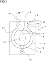
- FIG. 1 designates a top loading horizontal drum washing machine.
- a perforated rotating drum 2 of the machine 1 comprises a stainless steel cylindrical wrapper provided with a rectangular drum aperture 3 provided doors 4.
- the drum 2 is rotating within a plastic tub T mounted, with the interposition of known dampers, within a housing or cabinet C.
- Such cabinet C is provided with a lid L for closing an access opening 5 towards the drum 2.
- the tub T is fixed to the cabinet C and the drum 2 is mounted within said cabinet C and within the tub T to rotate about a horizontal axis X-X by means of a motor 6 mounted in the cabinet C and connected to the drum 2 through a pulley 7.
- the tub T has a tub opening 8 facing the access opening 5.
- the access opening 5 in the housing C is delimited by a first wall 9 protruding downwards in the cabinet towards the tub T.
- the tub opening 8 is delimited by a second wall 10 protruding upwards towards the access opening 5.
- a bellow sleeve 11 is connected to the first wall 9 and to the second wall 10 to delimit a tubular conduit extending between the access opening 5 and the tub opening 8.
- a first end of the bellow sleeve 11 surrounds the first wall 9 and a second end of the bellow sleeve 11 surrounds the second wall 10.
- a clamping framework 12 surrounds the first end of the bellow sleeve 11 to hold said first end onto the first wall 9.
- a further clamping framework 12 surrounds the second end of the bellow sleeve 11 to hold said second end onto the second wall 10.
- the ends of the bellow sleeve 11 and the respective clamping framework 12 may be positioned in a respective groove, not shown, made in the first wall 9 and/or in the second wall 10.
- the two clamping frameworks 12 have the same structure shown in figures 3 , 3A , 4 and 4A and detailed in the following passages.
- the access opening 5, the tub opening 8 and the clamping framework 12 present a substantially rectangular shape but other shapes may be adopted.
- the clamping framework 12 is preferably made of plastic and comprises a first U shaped frame 13 and a second U shaped frame 14. Each U shaped frame is a sort of rod shaped element profiled like a U.
- One end of the first U shaped frame 13 comprises a first part 15 of a connecting device 16.
- the other end of the first U shaped frame 13 comprises a second part 17 of another connecting device 16.
- One end of the second U shaped frame 14 comprises a first part 15 of the other connecting device 16.
- the other end of the second U shaped frame 14 comprises the second part 17 of the connecting device 16.
- the first part 15 of the first U shaped frame 13 is configured to be releasably connected to the second part 17 of the second U shaped frame 14 and the first part 15 of the second U shaped frame 14 is configured to be releasably connected to the second part 17 of the first U shaped frame 13 as shown in figures 3 and 4 .
- the assembly comprising a first part 15 and a second part 17 is a single connecting device 16 and will be detailed in the following passages.
- the first part 15 comprises an elongated element 18 attached, like an appendix, to a side of an end 19 of the frame 13, 14 and running parallel to said end 19. Said elongated element 18 and said end 19 delimit between them a slot 20.
- the elongated element 18 protrudes beyond said end 19 and presents a first and a second opposite faces lying substantially parallel to a surface onto which the clamping framework 12 lies.
- the upper face is flat and the lower face is provided with a first toothed profile 21.
- the first toothed profile 21 comprises a plurality of teeth placed in succession one after the other along a first direction Y. Each tooth presents a crest extending substantially perpendicular to the longitudinal extension of the elongated element 18.
- the end 19 is tapered and beveled.
- the second part 17 comprises a C-shaped body provided with a first tab 22, a second tab 23 and a portion 24 connecting the first tab 22 to the second tab 23.
- the connecting portion 23 is attached to an end 25 of the other frame 14, 13.
- the first tab 22, the second tab 23 and the connecting portion 24 delimit a seat 26 which opens laterally towards the outside of the clamping framework 12.
- Said seat 26 further presents a front opening 27 and a rear opening 28.
- the end 25 of the other frame 14, 13 is beveled to mate with the end 19 of the frame 13, 14.
- the first lower tab 22 presents an inner surface comprising a second toothed profile 29 facing upwards.
- the second toothed profile 29 is shorter than the first toothed profile 21 and comprises a plurality of teeth placed in succession one after the other along a second direction Z.
- Each tooth presents a crest extending substantially perpendicular to the longitudinal extension of the seat 26.
- the second upper tab 23 further presents an inner substantially smooth surface 30.
- the first tab 22 and/or the second tab 23 are flexible by exerting a force along a direction substantially perpendicular to the surface on which the clamping framework 12 lies.
- a protrusion 31 is placed on the frame 14, 13 close to the C-shaped body. Such protrusion 31 is spaced from the rear opening 28 and faces said rear opening 28. Further, the elongated element 18 presents a rear portion 32 configured to be clamped by an assembly tool together with the protrusion 31 as detailed in the following passages.
- the teeth of said first and second toothed profiles 21, 29 project substantially perpendicular to a surface S on which the clamping framework 12 lies (see figure 3 ).
- the first and second U shaped frames 13, 14 are assembled by inserting each elongated element 18 in the respective seat 26 through the front opening 27 of the C-shaped body along the common first and second direction Y, Z (arrows F1, F2). Simultaneously, the connecting portion 24 enters the slot 20.
- This movement may be performed manually or by means of a clamping tool, like a wrench, which grasps and brings the first part 15 towards the second part 17.
- the clamping tool acts on the rear portion 32 and the protrusion 31.
- the first toothed profile 21 faces the second toothed profile 29 and slides on said second toothed profile 29 thanks to the flexibility of the tabs 22, 23, until the bevels of the ends 19, 25 come into mutual contact.
- the inner substantially smooth surface 30 of the second tab 23 slides freely on the upper surface of the elongated element 18.
- the clamping framework 12 If the clamping framework 12 is to be disassembled, a force on the elongated element 18 along arrow F5 is exerted while the C-shaped body is held in place.
- the first tab 22 bends/deforms allowing the teeth of the first toothed profile 21 to disengage from the teeth of the second toothed profile 29. Then the elongated element 18 may be extracted along arrow F3 from the C-shaped body.
- F5 is the direction perpendicular to the surface on which the clamping framework 12 lies.
- clamping framework described herein by way of example may be subject to many possible variations without departing from the novelty spirit of the inventive idea.
- shape of the framework may be circular or elliptic.
Landscapes
- Engineering & Computer Science (AREA)
- Textile Engineering (AREA)
- Main Body Construction Of Washing Machines And Laundry Dryers (AREA)
- Clamps And Clips (AREA)
Description
- The present invention relates to a washing and/or drying machine comprising a housing having an access opening closed by a door, a wash tub having an opening and enclosing a rotating drum, a sleeve disposed between the access opening of the housing and the opening built into the wash tub. Preferably, the present invention relates to a top-loading washing and/or drying machine comprising a housing having a top access opening, a tub mounted in the cabinet with a top opening, a perforated drum rotatably mounted within said tub about a horizontal axis and having an aperture on its cylindrical side. In particular, the present invention refers to the clamp or clamps configured to fasten the sleeve to the housing and/or to the wash tub.
- It is known that washing and/or drying machines include a support cabinet, on which a washing tub is mounted, inside which rotates a drum, wherein the garments to be washed are placed. The tub has an opening through which the access to the drum is possible and clothes can be placed inside the drum. An opening closed by a door is also present on the cabinet or housing.
- Public document
EP1793029 discloses a machine for washing and/or drying clothes of top loading horizontal axis type, comprising a housing with an access opening closed by a door, a tub that has an opening and surrounds a rotary drum, and a sleeve between the access opening and the tub opening, comprises a sleeve with a fastener, one side of which is inserted into a U-shaped part of the sleeve that fits into a groove in the tub. The sleeve is usually made of flexible rubber or the like, it is subject to aging and deterioration and sometimes it should be replaced. The fastener allows to mount and dismantle said sleeve. - Document
KR 2000 0033178 A - The Applicant observed that known fasteners suffer from some drawbacks related to their assembly and disassembly.
- In fact, the Applicant verified that the known means for fixing the fasteners (like the lugs and bosses of
EP1793029 ) does not grant a safe attachment and are not easy to handle during mounting and dismantling of the sleeve. - It is therefore a main object of the present invention to overcome the above-mentioned drawbacks by providing a fastener in the form of a clamping framework surrounding at least one end of the sleeve which is easy to assemble and disassemble.
- Another object of the present invention is to provide a clamping framework which allows the sleeve to be mounted and dismantled quickly and easily.
- Another object of the present invention is to provide a clamping framework which allows the sleeve to be mounted safely into the washing and/or drying machine and assure the correct and steady position of said sleeve during operation of the machine.
- The Applicant has found that such objectives can be obtained by providing a clamping framework comprising two frames which are releasably connected one to the other through a toothed connecting device, wherein said connecting device can be unlocked by exerting a force on the first frame and/or the second frame along a direction substantially perpendicular to a surface on which the clamping framework lies.
- More specifically, present invention relates to a washing and/or drying machine as defined in
independent claim 1. Preferred embodiments of the present invention are the subject-matter of the dependent claims. - The Applicant verified that the position of the toothed profiles allows to move away the first toothed profile from the second toothed profile in order to disengage/unlock the connecting device in easy and rapid way. Therefore, the invention allows to disconnect the first frame from the second frame and to remove the clamping framework quickly and easily.
- The present invention, in at least one of the aforesaid aspects, can have one or more of the preferred characteristics that are described hereinbelow.
- In one aspect, the first toothed profile lies on a face of the elongated element substantially parallel to the surface on which the clamping framework lies.
- In one aspect, the second toothed profile is placed inside said seat and lies substantially parallel to the surface on which the clamping framework lies.
- In one aspect, the seat presents a front opening to allow insertion of the elongated element into said seat and engagement of the first toothed profile with the second toothed profile.
- In one aspect, the second part comprises a C-shaped body provided with a first tab, a second tab and a connecting portion delimiting said seat.
- In one aspect, said seat opens laterally towards the outside of the clamping framework.
- In one aspect, the connecting portion is configured to be inserted into the slot to engage the first and second toothed profiles.
- In one aspect, the first tab presents an inner surface comprising the second toothed profile facing the first toothed profile of the elongated element.
- In one aspect, the second tab presents an inner substantially smooth surface configured to come into contact with a surface of the elongated element opposite the first toothed profile.
- In one aspect, the first tab and/or the second tab are flexible so to allow disengagement of the first toothed profile from the second toothed profile by exerting a force on the first part and/or the second part along a direction substantially perpendicular to the surface on which the clamping framework lies. The term "flexible" means that the first tab and/or the second tab may be deformed during assembling and disassembling of the connecting device when subjected to the forces needed to engage/disengage the toothed profiles. When the first tab and/or the second tab are not subject to said forces, they are able to recover their un-deformed configurations.
- In one aspect, the first toothed profile extends only in part on the respective surface of the elongated element. In one aspect, the second toothed profile extends only in part on the respective surface of the first tab. In one aspect, the second toothed profile is shorter than the inner surface. These features allow an easy engagement and disengagement of the toothed profiles.
- In one aspect, the second part comprises a protrusion placed on the opposite side of the C-shaped body with respect to the front opening.
- In one aspect, a rear portion of the elongated element and said protrusion are configured to be clamped by an assembly tool to insert the elongated element in the seat through the front opening when mounting the clamping framework.
- In one aspect, the teeth of the first toothed profile are placed one after the other along a first direction.
- In one aspect, the teeth of the second toothed profile are placed one after the other along a second direction.
- In one aspect, engagement of the first toothed profile with the second toothed profile is performed by aligning the first and second directions and making the first toothed profile and the second toothed profile slide one over the other along said first and second common directions.
- In one aspect, the first U-shaped frame and the second U-shaped frame are identical and each comprises one first part placed on a first end and one second part placed on a second end.
- In one aspect the clamping framework is made of plastic material. In one aspect, each of the first and second frames is made of plastic, preferably molded in one piece.
- Further objects, features and advantages of the present invention will become apparent from the following detailed description and from the annexed drawings, which are supplied by way of non-limiting example, wherein:
-
Fig. 1 is a schematic view of a horizontal drum washing machine; -
Fig. 2 is a tridimensional view of a portion of the horizontal drum washing machine offigure 1 ; -
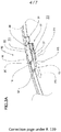
Fig. 3 is a clamping framework of the portion offigure 2 in a first configuration; -
Fig. 3A is an enlarged view of a part of the clamping framework offigure 3 ; -
Fig. 4 is the clamping framework offigure 3 in a second configuration; -
Fig. 4A is an enlarged view of a part of the clamping framework offigure 4 ; -
Fig. 5 is another view of an element of the clamping framework offigures 3 and4 . - Referring now to the annexed drawings, in
Fig. 1 reference numeral 1 designates a top loading horizontal drum washing machine. - A perforated rotating
drum 2 of themachine 1 comprises a stainless steel cylindrical wrapper provided with arectangular drum aperture 3 provideddoors 4. Thedrum 2 is rotating within a plastic tub T mounted, with the interposition of known dampers, within a housing or cabinet C. Such cabinet C is provided with a lid L for closing an access opening 5 towards thedrum 2. - The tub T is fixed to the cabinet C and the
drum 2 is mounted within said cabinet C and within the tub T to rotate about a horizontal axis X-X by means of amotor 6 mounted in the cabinet C and connected to thedrum 2 through apulley 7. - The tub T has a tub opening 8 facing the access opening 5. The
access opening 5 in the housing C is delimited by a first wall 9 protruding downwards in the cabinet towards the tub T. Thetub opening 8 is delimited by asecond wall 10 protruding upwards towards theaccess opening 5. - A
bellow sleeve 11 is connected to the first wall 9 and to thesecond wall 10 to delimit a tubular conduit extending between theaccess opening 5 and thetub opening 8. A first end of thebellow sleeve 11 surrounds the first wall 9 and a second end of thebellow sleeve 11 surrounds thesecond wall 10. - A clamping
framework 12 surrounds the first end of thebellow sleeve 11 to hold said first end onto the first wall 9. A further clampingframework 12 surrounds the second end of thebellow sleeve 11 to hold said second end onto thesecond wall 10. The ends of thebellow sleeve 11 and therespective clamping framework 12 may be positioned in a respective groove, not shown, made in the first wall 9 and/or in thesecond wall 10. - The two
clamping frameworks 12 have the same structure shown infigures 3 ,3A ,4 and4A and detailed in the following passages. In the annexed figures, theaccess opening 5, thetub opening 8 and the clampingframework 12 present a substantially rectangular shape but other shapes may be adopted. - The clamping
framework 12 is preferably made of plastic and comprises a first U shapedframe 13 and a second U shapedframe 14. Each U shaped frame is a sort of rod shaped element profiled like a U. - One end of the first U shaped
frame 13 comprises afirst part 15 of a connectingdevice 16. The other end of the first U shapedframe 13 comprises asecond part 17 of another connectingdevice 16. One end of the second U shapedframe 14 comprises afirst part 15 of the other connectingdevice 16. The other end of the second U shapedframe 14 comprises thesecond part 17 of the connectingdevice 16. Thefirst part 15 of the first U shapedframe 13 is configured to be releasably connected to thesecond part 17 of the second U shapedframe 14 and thefirst part 15 of the second U shapedframe 14 is configured to be releasably connected to thesecond part 17 of the first U shapedframe 13 as shown infigures 3 and4 . - The assembly comprising a
first part 15 and asecond part 17 is a single connectingdevice 16 and will be detailed in the following passages. - The
first part 15 comprises anelongated element 18 attached, like an appendix, to a side of anend 19 of theframe end 19. Saidelongated element 18 and saidend 19 delimit between them aslot 20. Theelongated element 18 protrudes beyond saidend 19 and presents a first and a second opposite faces lying substantially parallel to a surface onto which theclamping framework 12 lies. Referring tofigures 3A ,4A and5 , the upper face is flat and the lower face is provided with a firsttoothed profile 21. The firsttoothed profile 21 comprises a plurality of teeth placed in succession one after the other along a first direction Y. Each tooth presents a crest extending substantially perpendicular to the longitudinal extension of theelongated element 18. Theend 19 is tapered and beveled. - The
second part 17 comprises a C-shaped body provided with afirst tab 22, asecond tab 23 and aportion 24 connecting thefirst tab 22 to thesecond tab 23. The connectingportion 23 is attached to anend 25 of theother frame first tab 22, thesecond tab 23 and the connectingportion 24 delimit aseat 26 which opens laterally towards the outside of the clampingframework 12. Saidseat 26 further presents afront opening 27 and arear opening 28. Theend 25 of theother frame end 19 of theframe - Referring to
figures 3A and4A , the firstlower tab 22 presents an inner surface comprising a secondtoothed profile 29 facing upwards. The secondtoothed profile 29 is shorter than the firsttoothed profile 21 and comprises a plurality of teeth placed in succession one after the other along a second direction Z. Each tooth presents a crest extending substantially perpendicular to the longitudinal extension of theseat 26. The secondupper tab 23 further presents an inner substantiallysmooth surface 30. - The
first tab 22 and/or thesecond tab 23 are flexible by exerting a force along a direction substantially perpendicular to the surface on which theclamping framework 12 lies. - A
protrusion 31 is placed on theframe Such protrusion 31 is spaced from therear opening 28 and faces saidrear opening 28. Further, theelongated element 18 presents arear portion 32 configured to be clamped by an assembly tool together with theprotrusion 31 as detailed in the following passages. - The teeth of said first and second
toothed profiles clamping framework 12 lies (seefigure 3 ). - As shown in
figures 4 ,4A , the first and second U shaped frames 13, 14 are assembled by inserting eachelongated element 18 in therespective seat 26 through thefront opening 27 of the C-shaped body along the common first and second direction Y, Z (arrows F1, F2). Simultaneously, the connectingportion 24 enters theslot 20. - This movement may be performed manually or by means of a clamping tool, like a wrench, which grasps and brings the
first part 15 towards thesecond part 17. The clamping tool acts on therear portion 32 and theprotrusion 31. - The first
toothed profile 21 faces the secondtoothed profile 29 and slides on said secondtoothed profile 29 thanks to the flexibility of thetabs ends smooth surface 30 of thesecond tab 23 slides freely on the upper surface of theelongated element 18. - In this position, the teeth of the first
toothed profile 21 are engaged with the teeth of the second toothed profile 29 (Figure 3A ) and the relative movement along arrow F3 is prevented. Also the relative movement along arrow F4 is prevented by the connectingportion 24 placed in the slot 20 (Figure 3A ). - If the clamping
framework 12 is to be disassembled, a force on theelongated element 18 along arrow F5 is exerted while the C-shaped body is held in place. Thefirst tab 22 bends/deforms allowing the teeth of the firsttoothed profile 21 to disengage from the teeth of the secondtoothed profile 29. Then theelongated element 18 may be extracted along arrow F3 from the C-shaped body. - Please note that F5 is the direction perpendicular to the surface on which the
clamping framework 12 lies. - The clamping framework described herein by way of example may be subject to many possible variations without departing from the novelty spirit of the inventive idea. For instance shape of the framework may be circular or elliptic.
- It is also clear that in the practical implementation of the invention the illustrated details may have different shapes or be replaced with other technically equivalent elements.
- It can therefore be easily understood that the present invention is not limited to the above-described clamping framework but may be subject to many modifications, improvements or replacements of equivalent parts and elements without departing from the scope of the invention as clearly specified in the following claims.
Claims (13)
- A washing and/or drying machine, comprising:a housing (C) having an access opening (5);a rotating drum (2);a tub (T) having a tub opening (8) and enclosing the rotating drum (2);a sleeve (11) disposed between the access opening (5) of the housing (C) and the tub opening (8) of the tub (T);at least one clamping framework (12) surrounding at least one end of the sleeve (11) to fasten said sleeve (11) to the housing (C) and/or to the tub (T);said at least one clamping framework (12) comprising a first U-shaped frame (13) and a second U-shaped frame (14) and a first connecting device (16) and a second connecting device (16), each of the first and second connecting device (16) being configured to releasably connect the first frame (13) to the second frame (14),each of the first and the second connecting device (16) comprising a first part (15) provided with a first toothed profile (21) engaging a second part (17) provided with a second toothed profile (29), wherein one end of the first U shaped frame (13) comprises the first part (15) of the first connecting device (16), the other end of the first U shaped frame (13) comprises the second part (17) of the second connecting device (16);wherein one end of the second U shaped frame (14) comprises a first part (15) of the second connecting device (16), the other end of the second U shaped frame (14) comprises the second part (17) of the first connecting device (16);wherein each first part (15) comprises an elongated element (18) provided with the first toothed profile (21) and delimiting, together with the respective end (19) of the first frame (13) or of the second frame (4), a slot (20);wherein each second part (17) presents a seat (26) placed at the respective end (25) of the second frame (14) or of the first frame (13) and configured to accommodate the elongated element (18);wherein the teeth of said first and second toothed profiles (21, 29) project substantially perpendicular to a surface (S) on which the clamping framework (12) lies.
- The machine of claim 1, wherein the first toothed profile (21) lies on a face of the elongated element (18) substantially parallel to the surface (S) on which the clamping framework (12) lies.
- The machine of claim 1 or 2, wherein the second toothed profile (29) is placed inside said seat (26) and lies substantially parallel to the surface (S) on which the clamping framework (12) lies.
- The machine of claim 3, wherein the seat (26) presents a front opening (27) to allow insertion of the elongated element (18) into said seat (26) and engagement of the first toothed profile (21) with the second toothed profile (29).
- The machine of any of the previous claims, wherein the second part (17) comprises a C-shaped body provided with a first tab (22), a second tab (23) and a connecting portion (24) delimiting said seat (26).
- The machine of claim 5, wherein said seat (26) opens laterally towards the outside of the clamping framework (12).
- The machine of claim 5 or 6, wherein the connecting portion (24) is configured to be inserted into the slot (20) to engage the first and second toothed profiles (21, 29).
- The machine of claim 5, 6 or 7, wherein, when the connecting device (16) is assembled, the first tab (22) presents an inner surface comprising the second toothed profile (29) facing the first toothed profile (21) of the elongated element (18); wherein the second tab (23) presents an inner substantially smooth surface (30) configured to come into contact with a surface of the elongated element (18) opposite the first toothed profile (21).
- The machine of any of claims 5 to 8, wherein the first tab (22) and/or the second tab (23) are flexible so to allow disengagement of the first toothed profile (21) from the second toothed profile (29) by exerting a force on the first part (15) and/or the second part (17) along a direction substantially perpendicular to the surface (S) on which the clamping framework (12) lies.
- The machine of claim 8, wherein the second toothed profile (29) is shorter than the inner surface to allow an easy disengagement of the toothed profiles (21, 29).
- The machine of any of claims 5 to 10, wherein the second part (17) comprises a protrusion (31) placed on the opposite side of the C-shaped body with respect to the front opening (27), wherein a rear portion (32) of the elongated element (18) and said protrusion (31) are configured to be clamped by an assembly tool to insert the elongated element (18) in the seat (26) through the front opening (27) when mounting the clamping framework (12).
- The machine of any of the preceding claims, wherein the teeth of the first toothed profile (21) are placed one after the other along a first direction (Y); wherein the teeth of the second toothed profile (29) are placed one after the other along a second direction (Z); wherein engagement of the first toothed profile (21) with the second toothed profile (29) is performed by aligning the first and second directions (Y, Z) and making the first toothed profile (21) and the second toothed profile (29) slide one over the other along said first and second common directions (Y, Z).
- The machine of any of the preceding claims, wherein the first U-shaped frame (13) and the second U-shaped frame (14) are identical and each comprises one first part (15) placed on a first end and one second part (17) placed on a second end.
Priority Applications (1)
| Application Number | Priority Date | Filing Date | Title |
|---|---|---|---|
| EP16203519.0A EP3333302B1 (en) | 2016-12-12 | 2016-12-12 | Washing and/or drying machine |
Applications Claiming Priority (1)
| Application Number | Priority Date | Filing Date | Title |
|---|---|---|---|
| EP16203519.0A EP3333302B1 (en) | 2016-12-12 | 2016-12-12 | Washing and/or drying machine |
Publications (2)
| Publication Number | Publication Date |
|---|---|
| EP3333302A1 EP3333302A1 (en) | 2018-06-13 |
| EP3333302B1 true EP3333302B1 (en) | 2020-06-10 |
Family
ID=57542897
Family Applications (1)
| Application Number | Title | Priority Date | Filing Date |
|---|---|---|---|
| EP16203519.0A Active EP3333302B1 (en) | 2016-12-12 | 2016-12-12 | Washing and/or drying machine |
Country Status (1)
| Country | Link |
|---|---|
| EP (1) | EP3333302B1 (en) |
Families Citing this family (1)
| Publication number | Priority date | Publication date | Assignee | Title |
|---|---|---|---|---|
| CN111733571A (en) * | 2019-03-19 | 2020-10-02 | 青岛海尔滚筒洗衣机有限公司 | A washing machine observation window gasket fastening ring and washing machine |
Family Cites Families (5)
| Publication number | Priority date | Publication date | Assignee | Title |
|---|---|---|---|---|
| FR2296048A1 (en) * | 1974-12-24 | 1976-07-23 | Thomson Brandt | DRUM WASHING MACHINE |
| IT8434064V0 (en) * | 1984-10-22 | 1984-10-22 | Zanussi Elettrodomestici | GASKET, IN PARTICULAR FOR HOUSEHOLD APPLIANCES. |
| KR100546577B1 (en) * | 1998-11-20 | 2006-03-23 | 엘지전자 주식회사 | tub gasket clamp in drum-type washing machine |
| EP1746321A1 (en) * | 2005-07-22 | 2007-01-24 | IMET S.r.l. | Fastening device for cylindrical bodies, especially tubes and cables |
| FR2893955B1 (en) | 2005-11-30 | 2007-12-28 | Brandt Ind Sas | WASHING OR DRYING MACHINE EQUIPPED WITH A BOND LINK BODY AND METHOD FOR ASSEMBLING THE SAME |
-
2016
- 2016-12-12 EP EP16203519.0A patent/EP3333302B1/en active Active
Non-Patent Citations (1)
| Title |
|---|
| None * |
Also Published As
| Publication number | Publication date |
|---|---|
| EP3333302A1 (en) | 2018-06-13 |
Similar Documents
| Publication | Publication Date | Title |
|---|---|---|
| EP2861792B1 (en) | Laundry treatment device with door assembly | |
| RU2628962C2 (en) | Interface for portable kitchen appliances | |
| KR102482469B1 (en) | Washing Machine | |
| US8356495B2 (en) | Laundry apparatus | |
| KR102255461B1 (en) | Switchgear cabinet housing hinge and corresponding switchgear cabinet housing and mounting method | |
| EP1936018A1 (en) | System for screwless fixing of a body to a panel | |
| WO2016069125A1 (en) | Retaining device, in particular for removably connecting vehicle body parts | |
| KR101966087B1 (en) | Connection device for assembly furniture | |
| EP3333302A1 (en) | Washing and/or drying machine | |
| CN106471301A (en) | fixture | |
| DE502008002213D1 (en) | SET INCLUDING A HOME DEVICE AND AT LEAST A TRANSPORT BACKUP | |
| KR20090119538A (en) | Clothing processing device | |
| CN105557080B (en) | Fan device | |
| CN110872779B (en) | Clothes processing equipment | |
| KR101945319B1 (en) | Coupling device for coupling a friction damper on a washing machine | |
| CN111621964B (en) | Door body device and clothes treatment equipment with same | |
| KR20060026317A (en) | dryer | |
| KR20080037420A (en) | Drum Washing Machine | |
| EP2204486A2 (en) | Electrical home appliance with top cover | |
| EP1923498A2 (en) | Frontloading washing machine | |
| KR20140084947A (en) | Drum type washing machine | |
| KR102048023B1 (en) | Auto sliding door appraratus | |
| EP1882437B1 (en) | Device for fixing a built-in electric household appliance inside the associated compartment of a furniture unit | |
| EP2865800A1 (en) | Assembly method and assembly apparatus of the washing tub of a laundry washing machine | |
| WO2016155785A1 (en) | Laundry washing machine having an improved leak-proof door assembly |
Legal Events
| Date | Code | Title | Description |
|---|---|---|---|
| PUAI | Public reference made under article 153(3) epc to a published international application that has entered the european phase |
Free format text: ORIGINAL CODE: 0009012 |
|
| STAA | Information on the status of an ep patent application or granted ep patent |
Free format text: STATUS: THE APPLICATION HAS BEEN PUBLISHED |
|
| AK | Designated contracting states |
Kind code of ref document: A1 Designated state(s): AL AT BE BG CH CY CZ DE DK EE ES FI FR GB GR HR HU IE IS IT LI LT LU LV MC MK MT NL NO PL PT RO RS SE SI SK SM TR |
|
| AX | Request for extension of the european patent |
Extension state: BA ME |
|
| STAA | Information on the status of an ep patent application or granted ep patent |
Free format text: STATUS: REQUEST FOR EXAMINATION WAS MADE |
|
| 17P | Request for examination filed |
Effective date: 20181212 |
|
| RBV | Designated contracting states (corrected) |
Designated state(s): AL AT BE BG CH CY CZ DE DK EE ES FI FR GB GR HR HU IE IS IT LI LT LU LV MC MK MT NL NO PL PT RO RS SE SI SK SM TR |
|
| STAA | Information on the status of an ep patent application or granted ep patent |
Free format text: STATUS: EXAMINATION IS IN PROGRESS |
|
| 17Q | First examination report despatched |
Effective date: 20190918 |
|
| GRAP | Despatch of communication of intention to grant a patent |
Free format text: ORIGINAL CODE: EPIDOSNIGR1 |
|
| STAA | Information on the status of an ep patent application or granted ep patent |
Free format text: STATUS: GRANT OF PATENT IS INTENDED |
|
| INTG | Intention to grant announced |
Effective date: 20200310 |
|
| GRAS | Grant fee paid |
Free format text: ORIGINAL CODE: EPIDOSNIGR3 |
|
| GRAA | (expected) grant |
Free format text: ORIGINAL CODE: 0009210 |
|
| STAA | Information on the status of an ep patent application or granted ep patent |
Free format text: STATUS: THE PATENT HAS BEEN GRANTED |
|
| AK | Designated contracting states |
Kind code of ref document: B1 Designated state(s): AL AT BE BG CH CY CZ DE DK EE ES FI FR GB GR HR HU IE IS IT LI LT LU LV MC MK MT NL NO PL PT RO RS SE SI SK SM TR |
|
| REG | Reference to a national code |
Ref country code: GB Ref legal event code: FG4D |
|
| REG | Reference to a national code |
Ref country code: AT Ref legal event code: REF Ref document number: 1279274 Country of ref document: AT Kind code of ref document: T Effective date: 20200615 Ref country code: CH Ref legal event code: EP |
|
| REG | Reference to a national code |
Ref country code: DE Ref legal event code: R096 Ref document number: 602016037820 Country of ref document: DE |
|
| REG | Reference to a national code |
Ref country code: IE Ref legal event code: FG4D |
|
| REG | Reference to a national code |
Ref country code: LT Ref legal event code: MG4D |
|
| PG25 | Lapsed in a contracting state [announced via postgrant information from national office to epo] |
Ref country code: FI Free format text: LAPSE BECAUSE OF FAILURE TO SUBMIT A TRANSLATION OF THE DESCRIPTION OR TO PAY THE FEE WITHIN THE PRESCRIBED TIME-LIMIT Effective date: 20200610 Ref country code: SE Free format text: LAPSE BECAUSE OF FAILURE TO SUBMIT A TRANSLATION OF THE DESCRIPTION OR TO PAY THE FEE WITHIN THE PRESCRIBED TIME-LIMIT Effective date: 20200610 Ref country code: NO Free format text: LAPSE BECAUSE OF FAILURE TO SUBMIT A TRANSLATION OF THE DESCRIPTION OR TO PAY THE FEE WITHIN THE PRESCRIBED TIME-LIMIT Effective date: 20200910 Ref country code: GR Free format text: LAPSE BECAUSE OF FAILURE TO SUBMIT A TRANSLATION OF THE DESCRIPTION OR TO PAY THE FEE WITHIN THE PRESCRIBED TIME-LIMIT Effective date: 20200911 Ref country code: LT Free format text: LAPSE BECAUSE OF FAILURE TO SUBMIT A TRANSLATION OF THE DESCRIPTION OR TO PAY THE FEE WITHIN THE PRESCRIBED TIME-LIMIT Effective date: 20200610 |
|
| REG | Reference to a national code |
Ref country code: NL Ref legal event code: MP Effective date: 20200610 |
|
| PG25 | Lapsed in a contracting state [announced via postgrant information from national office to epo] |
Ref country code: BG Free format text: LAPSE BECAUSE OF FAILURE TO SUBMIT A TRANSLATION OF THE DESCRIPTION OR TO PAY THE FEE WITHIN THE PRESCRIBED TIME-LIMIT Effective date: 20200910 Ref country code: RS Free format text: LAPSE BECAUSE OF FAILURE TO SUBMIT A TRANSLATION OF THE DESCRIPTION OR TO PAY THE FEE WITHIN THE PRESCRIBED TIME-LIMIT Effective date: 20200610 Ref country code: LV Free format text: LAPSE BECAUSE OF FAILURE TO SUBMIT A TRANSLATION OF THE DESCRIPTION OR TO PAY THE FEE WITHIN THE PRESCRIBED TIME-LIMIT Effective date: 20200610 Ref country code: HR Free format text: LAPSE BECAUSE OF FAILURE TO SUBMIT A TRANSLATION OF THE DESCRIPTION OR TO PAY THE FEE WITHIN THE PRESCRIBED TIME-LIMIT Effective date: 20200610 |
|
| REG | Reference to a national code |
Ref country code: AT Ref legal event code: MK05 Ref document number: 1279274 Country of ref document: AT Kind code of ref document: T Effective date: 20200610 |
|
| PG25 | Lapsed in a contracting state [announced via postgrant information from national office to epo] |
Ref country code: NL Free format text: LAPSE BECAUSE OF FAILURE TO SUBMIT A TRANSLATION OF THE DESCRIPTION OR TO PAY THE FEE WITHIN THE PRESCRIBED TIME-LIMIT Effective date: 20200610 Ref country code: AL Free format text: LAPSE BECAUSE OF FAILURE TO SUBMIT A TRANSLATION OF THE DESCRIPTION OR TO PAY THE FEE WITHIN THE PRESCRIBED TIME-LIMIT Effective date: 20200610 |
|
| PG25 | Lapsed in a contracting state [announced via postgrant information from national office to epo] |
Ref country code: EE Free format text: LAPSE BECAUSE OF FAILURE TO SUBMIT A TRANSLATION OF THE DESCRIPTION OR TO PAY THE FEE WITHIN THE PRESCRIBED TIME-LIMIT Effective date: 20200610 Ref country code: AT Free format text: LAPSE BECAUSE OF FAILURE TO SUBMIT A TRANSLATION OF THE DESCRIPTION OR TO PAY THE FEE WITHIN THE PRESCRIBED TIME-LIMIT Effective date: 20200610 Ref country code: ES Free format text: LAPSE BECAUSE OF FAILURE TO SUBMIT A TRANSLATION OF THE DESCRIPTION OR TO PAY THE FEE WITHIN THE PRESCRIBED TIME-LIMIT Effective date: 20200610 Ref country code: PT Free format text: LAPSE BECAUSE OF FAILURE TO SUBMIT A TRANSLATION OF THE DESCRIPTION OR TO PAY THE FEE WITHIN THE PRESCRIBED TIME-LIMIT Effective date: 20201012 Ref country code: CZ Free format text: LAPSE BECAUSE OF FAILURE TO SUBMIT A TRANSLATION OF THE DESCRIPTION OR TO PAY THE FEE WITHIN THE PRESCRIBED TIME-LIMIT Effective date: 20200610 Ref country code: RO Free format text: LAPSE BECAUSE OF FAILURE TO SUBMIT A TRANSLATION OF THE DESCRIPTION OR TO PAY THE FEE WITHIN THE PRESCRIBED TIME-LIMIT Effective date: 20200610 Ref country code: SM Free format text: LAPSE BECAUSE OF FAILURE TO SUBMIT A TRANSLATION OF THE DESCRIPTION OR TO PAY THE FEE WITHIN THE PRESCRIBED TIME-LIMIT Effective date: 20200610 |
|
| PG25 | Lapsed in a contracting state [announced via postgrant information from national office to epo] |
Ref country code: IS Free format text: LAPSE BECAUSE OF FAILURE TO SUBMIT A TRANSLATION OF THE DESCRIPTION OR TO PAY THE FEE WITHIN THE PRESCRIBED TIME-LIMIT Effective date: 20201010 Ref country code: SK Free format text: LAPSE BECAUSE OF FAILURE TO SUBMIT A TRANSLATION OF THE DESCRIPTION OR TO PAY THE FEE WITHIN THE PRESCRIBED TIME-LIMIT Effective date: 20200610 Ref country code: PL Free format text: LAPSE BECAUSE OF FAILURE TO SUBMIT A TRANSLATION OF THE DESCRIPTION OR TO PAY THE FEE WITHIN THE PRESCRIBED TIME-LIMIT Effective date: 20200610 |
|
| REG | Reference to a national code |
Ref country code: DE Ref legal event code: R097 Ref document number: 602016037820 Country of ref document: DE |
|
| PLBE | No opposition filed within time limit |
Free format text: ORIGINAL CODE: 0009261 |
|
| STAA | Information on the status of an ep patent application or granted ep patent |
Free format text: STATUS: NO OPPOSITION FILED WITHIN TIME LIMIT |
|
| PG25 | Lapsed in a contracting state [announced via postgrant information from national office to epo] |
Ref country code: DK Free format text: LAPSE BECAUSE OF FAILURE TO SUBMIT A TRANSLATION OF THE DESCRIPTION OR TO PAY THE FEE WITHIN THE PRESCRIBED TIME-LIMIT Effective date: 20200610 |
|
| 26N | No opposition filed |
Effective date: 20210311 |
|
| PG25 | Lapsed in a contracting state [announced via postgrant information from national office to epo] |
Ref country code: SI Free format text: LAPSE BECAUSE OF FAILURE TO SUBMIT A TRANSLATION OF THE DESCRIPTION OR TO PAY THE FEE WITHIN THE PRESCRIBED TIME-LIMIT Effective date: 20200610 |
|
| REG | Reference to a national code |
Ref country code: CH Ref legal event code: PL |
|
| PG25 | Lapsed in a contracting state [announced via postgrant information from national office to epo] |
Ref country code: MC Free format text: LAPSE BECAUSE OF FAILURE TO SUBMIT A TRANSLATION OF THE DESCRIPTION OR TO PAY THE FEE WITHIN THE PRESCRIBED TIME-LIMIT Effective date: 20200610 |
|
| REG | Reference to a national code |
Ref country code: BE Ref legal event code: MM Effective date: 20201231 |
|
| PG25 | Lapsed in a contracting state [announced via postgrant information from national office to epo] |
Ref country code: LU Free format text: LAPSE BECAUSE OF NON-PAYMENT OF DUE FEES Effective date: 20201212 Ref country code: IE Free format text: LAPSE BECAUSE OF NON-PAYMENT OF DUE FEES Effective date: 20201212 |
|
| PG25 | Lapsed in a contracting state [announced via postgrant information from national office to epo] |
Ref country code: LI Free format text: LAPSE BECAUSE OF NON-PAYMENT OF DUE FEES Effective date: 20201231 Ref country code: CH Free format text: LAPSE BECAUSE OF NON-PAYMENT OF DUE FEES Effective date: 20201231 |
|
| PG25 | Lapsed in a contracting state [announced via postgrant information from national office to epo] |
Ref country code: TR Free format text: LAPSE BECAUSE OF FAILURE TO SUBMIT A TRANSLATION OF THE DESCRIPTION OR TO PAY THE FEE WITHIN THE PRESCRIBED TIME-LIMIT Effective date: 20200610 Ref country code: MT Free format text: LAPSE BECAUSE OF FAILURE TO SUBMIT A TRANSLATION OF THE DESCRIPTION OR TO PAY THE FEE WITHIN THE PRESCRIBED TIME-LIMIT Effective date: 20200610 Ref country code: CY Free format text: LAPSE BECAUSE OF FAILURE TO SUBMIT A TRANSLATION OF THE DESCRIPTION OR TO PAY THE FEE WITHIN THE PRESCRIBED TIME-LIMIT Effective date: 20200610 |
|
| PG25 | Lapsed in a contracting state [announced via postgrant information from national office to epo] |
Ref country code: MK Free format text: LAPSE BECAUSE OF FAILURE TO SUBMIT A TRANSLATION OF THE DESCRIPTION OR TO PAY THE FEE WITHIN THE PRESCRIBED TIME-LIMIT Effective date: 20200610 |
|
| PG25 | Lapsed in a contracting state [announced via postgrant information from national office to epo] |
Ref country code: BE Free format text: LAPSE BECAUSE OF NON-PAYMENT OF DUE FEES Effective date: 20201231 |
|
| P01 | Opt-out of the competence of the unified patent court (upc) registered |
Effective date: 20230522 |
|
| PGFP | Annual fee paid to national office [announced via postgrant information from national office to epo] |
Ref country code: GB Payment date: 20251223 Year of fee payment: 10 |
|
| PGFP | Annual fee paid to national office [announced via postgrant information from national office to epo] |
Ref country code: IT Payment date: 20251205 Year of fee payment: 10 |
|
| PGFP | Annual fee paid to national office [announced via postgrant information from national office to epo] |
Ref country code: FR Payment date: 20251223 Year of fee payment: 10 |
|
| PGFP | Annual fee paid to national office [announced via postgrant information from national office to epo] |
Ref country code: DE Payment date: 20251229 Year of fee payment: 10 |