EP3333109A1 - Automatic winder and winding speed control method of automatic winder - Google Patents
Automatic winder and winding speed control method of automatic winder Download PDFInfo
- Publication number
- EP3333109A1 EP3333109A1 EP17203581.8A EP17203581A EP3333109A1 EP 3333109 A1 EP3333109 A1 EP 3333109A1 EP 17203581 A EP17203581 A EP 17203581A EP 3333109 A1 EP3333109 A1 EP 3333109A1
- Authority
- EP
- European Patent Office
- Prior art keywords
- winding
- time point
- yarn
- doffing
- yarn supplying
- Prior art date
- Legal status (The legal status is an assumption and is not a legal conclusion. Google has not performed a legal analysis and makes no representation as to the accuracy of the status listed.)
- Granted
Links
Images





Classifications
-
- B—PERFORMING OPERATIONS; TRANSPORTING
- B65—CONVEYING; PACKING; STORING; HANDLING THIN OR FILAMENTARY MATERIAL
- B65H—HANDLING THIN OR FILAMENTARY MATERIAL, e.g. SHEETS, WEBS, CABLES
- B65H54/00—Winding, coiling, or depositing filamentary material
- B65H54/70—Other constructional features of yarn-winding machines
- B65H54/74—Driving arrangements
-
- B—PERFORMING OPERATIONS; TRANSPORTING
- B65—CONVEYING; PACKING; STORING; HANDLING THIN OR FILAMENTARY MATERIAL
- B65H—HANDLING THIN OR FILAMENTARY MATERIAL, e.g. SHEETS, WEBS, CABLES
- B65H54/00—Winding, coiling, or depositing filamentary material
- B65H54/02—Winding and traversing material on to reels, bobbins, tubes, or like package cores or formers
-
- B—PERFORMING OPERATIONS; TRANSPORTING
- B65—CONVEYING; PACKING; STORING; HANDLING THIN OR FILAMENTARY MATERIAL
- B65H—HANDLING THIN OR FILAMENTARY MATERIAL, e.g. SHEETS, WEBS, CABLES
- B65H54/00—Winding, coiling, or depositing filamentary material
- B65H54/02—Winding and traversing material on to reels, bobbins, tubes, or like package cores or formers
- B65H54/40—Arrangements for rotating packages
- B65H54/52—Drive contact pressure control, e.g. pressing arrangements
-
- B—PERFORMING OPERATIONS; TRANSPORTING
- B65—CONVEYING; PACKING; STORING; HANDLING THIN OR FILAMENTARY MATERIAL
- B65H—HANDLING THIN OR FILAMENTARY MATERIAL, e.g. SHEETS, WEBS, CABLES
- B65H67/00—Replacing or removing cores, receptacles, or completed packages at paying-out, winding, or depositing stations
- B65H67/06—Supplying cores, receptacles, or packages to, or transporting from, winding or depositing stations
-
- D—TEXTILES; PAPER
- D01—NATURAL OR MAN-MADE THREADS OR FIBRES; SPINNING
- D01H—SPINNING OR TWISTING
- D01H9/00—Arrangements for replacing or removing bobbins, cores, receptacles, or completed packages at paying-out or take-up stations ; Combination of spinning-winding machine
- D01H9/18—Arrangements for replacing or removing bobbins, cores, receptacles, or completed packages at paying-out or take-up stations ; Combination of spinning-winding machine for supplying bobbins, cores, receptacles, or completed packages to, or transporting from, paying-out or take-up stations ; Arrangements to prevent unwinding of roving from roving bobbins
-
- B—PERFORMING OPERATIONS; TRANSPORTING
- B65—CONVEYING; PACKING; STORING; HANDLING THIN OR FILAMENTARY MATERIAL
- B65H—HANDLING THIN OR FILAMENTARY MATERIAL, e.g. SHEETS, WEBS, CABLES
- B65H2701/00—Handled material; Storage means
- B65H2701/30—Handled filamentary material
- B65H2701/31—Textiles threads or artificial strands of filaments
-
- D—TEXTILES; PAPER
- D01—NATURAL OR MAN-MADE THREADS OR FIBRES; SPINNING
- D01H—SPINNING OR TWISTING
- D01H1/00—Spinning or twisting machines in which the product is wound-up continuously
- D01H1/02—Spinning or twisting machines in which the product is wound-up continuously ring type
Definitions
- the present invention relates to an automatic winder and a winding speed control method of the automatic winder.
- a yarn winding system including a spinning machine with a plurality of spinning units adapted to form a yarn supplying bobbin, and an automatic winder including a plurality of winding units adapted to wind the yarn from the yarn supplying bobbin to form a package
- an automatic winder including a plurality of winding units adapted to wind the yarn from the yarn supplying bobbin to form a package
- a medium is arranged on a bobbin mounting tray that is transported in a circulating manner between the spinning machine and the automatic winder, and yarn processing information of the winder is written to the medium by a writing device.
- the yarn processing information written to the medium is read by a reading device, and managed by a management computer.
- Optimizing the operation control includes, for example, appropriately switching a processing speed of the automatic winder according to a processing status of the spinning machine, which is a pre-stage machine of the automatic winder, or appropriately operating the automatic winder according to completion condition of spinning in the spinning machine.
- the optimization of the operation control of the automatic winder is realized by transmitting spinning information of the spinning machine to the automatic winder through wired communication or wireless communication.
- the spinning machines at the pre-stage of the automatic winder include various types of spinning machines with different specifications.
- the automatic winder cannot receive the spinning information of the spinning machine, and the operation control of the automatic winder cannot be optimized.
- An automatic winder of the present invention includes a plurality of winding units adapted to wind a yarn from the yarn supplying bobbin formed by a spinning machine to form a package.
- the automatic winder includes an input section adapted to input spinning information including information relating to at least one of a processing status of formation of the yarn supplying bobbin and a doffing execution signal; and a control section adapted to determine a winding speed of when the winding unit winds a yarn from the yarn supplying bobbin based on the spinning information input by the input section.
- the spinning information including the information relating to at least one of the processing status of the formation of the yarn supplying bobbin and the doffing execution signal is input to the automatic winder.
- the automatic winder controls the operation of the automatic winder based on the input spinning information.
- the optimization of the operation control of the automatic winder can be realized by carrying out the operation control of the automatic winder based on the input spinning information.
- the control section controls an operation of the winding unit to wind the yarn from the yarn supplying bobbin at the determined winding speed based on the information relating to the processing status of the formation of the yarn supplying bobbin.
- the automatic winder can obtain the spinning status of the spinning machine based on the input information relating to the processing status of the formation of the yarn supplying bobbin.
- the automatic winder thus can realize the operation control adapted to the spinning status of the spinning machine.
- the control section obtains a time point of next doffing of the spinning machine based on the information relating to the processing status of the formation of the yarn supplying bobbin, obtains a yarn supplying bobbin processing time, which is a time required for the winding unit to wind one yarn supplying bobbin, based on a target winding number, which is a number of yarn supplying bobbins to be wound by the time point of the next doffing, and further calculates a time required to process the target winding number to determine a winding speed of when the winding unit winds the yarn from the yarn supplying bobbin.
- the control section calculates a time point at which winding of the target winding number is finished from the time required to process the target winding number, increases the winding speed of the winding unit when the time point at which the winding of the target winding number is finished is later than the time point of the next doffing, reduces the winding speed of the winding unit when the time point at which the winding of the target winding number is finished is earlier than the time point of the next doffing by greater than or equal to a predetermined time, and does not change the winding speed of the winding unit when the time point at which the winding of the target winding number is finished is the same time point as the time point of the next doffing or earlier within the predetermined time.
- a time point of the next doffing of the spinning machine is obtained, and a time required to process the target winding number is calculated from the target winding number, which is the number of yarn supplying bobbins to be wound by the time point of the next doffing, and the yarn supplying bobbin processing time, which is the time required for the winding unit to wind one yarn supplying bobbin.
- the winding step of the automatic winder thus can be more accurately adapted to the spinning step of the spinning machine.
- the control section calculates doffing information based on the doffing execution signal serving as the spinning information input by the input section, and determines the winding speed of when the winding unit winds a yarn from the yarn supplying bobbin based on the calculated doffing information.
- the control section obtains a time point of next doffing of the spinning machine based on the calculated doffing information, obtains a yarn supplying bobbin processing time, which is a time required for the winding unit to wind one yarn supplying bobbin, based on a target winding number, which is a number of yarn supplying bobbins to be wound by the time point of the next doffing, and further calculates a time required to process the target winding number to determine a winding speed of when the winding unit winds the yarn from the yarn supplying bobbin.
- control section calculates a time point at which winding of the target winding number is finished from the time required to process the target winding number, increases the winding speed of the winding unit when the time point at which the winding of the target winding number is finished is later than the time point of the next doffing, reduces the winding speed of the winding unit when the time point at which the winding of the target winding number is finished is earlier than the time point of the next doffing by greater than or equal to a predetermined time, and does not change the winding speed of the winding unit when the time point at which the winding of the target winding number is finished is the same time point as the time point of the next doffing or earlier within the predetermined time.
- the winding process of the automatic winder can be more accurately adapted to the spinning step of the spinning machine.
- the control section changes the winding speed of the winding unit within a range of a fluctuation restriction that restricts a changing range of the winding speed.
- the winding state of the package can be prevented from being greatly changed by the rapid speed change, and the change in the winding state of the package can be avoided.
- the quality of the package thus will not be downgraded.
- the fluctuation restriction can be changed by the input section. As the rate of speed change can be changed in accordance with the type of yarn to be wound, the winding speed range suitable for the type of yarn and the winding conditions will not be exceeded. The quality of the package thus will not be downgraded.
- the optimization of the operation control of the automatic winder can be realized.
- a yarn winding system 1 includes a roving machine 2, a spinning machine 3, and an automatic winder 4.
- the roving machine 2 is adapted to produce a rove from a sliver, and wind the rove to form a roving bobbin.
- the spinning machine 3 is adapted to produce a yarn from the rove, and wind the yarn to form a yarn supplying bobbin 11.
- the automatic winder 4 is adapted to wind the yarn from the yarn supplying bobbin 11 to form a package 15.
- the automatic winder 4 includes a bobbin transferring device (bobbin transferring section) 5.
- the bobbin transferring device 5 is adapted to transfer the yarn supplying bobbin 11 from the spinning machine 3 to the automatic winder 4, and transfer an empty bobbin 12 (bobbin around which a yarn is not wound) from the automatic winder 4 to the spinning machine 3.
- the bobbin transferring device 5 includes a bobbin preparing device (bobbin preparing section) 7 and a remaining yarn processing device, and the like.
- the bobbin preparing device 7 is adapted to carry out a preliminary preparation for the automatic winder 4 to process the yarn of the yarn supplying bobbin 11. If the yarn remains on the bobbin 12 discharged from the yarn supplying bobbin 11, the remaining yarn processing device removes the yarn to obtain the empty bobbin 12.
- the bobbin transferring device 5 has a complex transportation path with many curves.
- the yarn supplying bobbin 11 and the empty bobbin 12 are respectively transferred while being set on a tray 6.
- the tray 6 includes a circular plate shaped base portion 61, a pin 62 that projects out toward an upper side from the base portion 61, and an RF (Radio Frequency) tag 63 incorporated in the base portion 61.
- the RF tag (recording section) 63 stores information relating to the yarn supplying bobbin 11 set on the tray 6.
- the status of the yarn supplying bobbin 11 set on the tray 6 is managed by an RFID (Radio Frequency Identification: Identification by radio wave) technique.
- the roving machine 2 includes a control device 21 adapted to control the operation of the roving machine 2, and a plurality of roving units 22 adapted to form the roving bobbin.
- the control device 21 includes a display section 21a such as a display, and an operation section 21b such as input keys.
- the display section 21a displays an operational status of each roving unit 22, and the like.
- the operation section 21b is provided for an operator to carry out setting of the operational conditions of each roving unit 22, and the like.
- the spinning machine 3 includes a control device 31 adapted to control the operation of the spinning machine 3, and a plurality of spinning units 32 adapted to form the yarn supplying bobbin 11.
- the control device 31 includes a display section 31a such as a display, and an operation section 31b such as input keys.
- the display section 31a displays an operational status of each spinning unit 32, and the like.
- the operation section 31b is provided for an operator to carry out setting of the operational conditions of each spinning unit 32, and the like.
- the spinning unit 32 includes a draft device 33 and a twist applying device 34.
- the draft device 33 includes a pair of back rollers 33a, a pair of middle rollers 33b, and a pair of front rollers 33c.
- the pair of back rollers 33a, the pair of middle rollers 33b, and the pair of front rollers 33c are each configured by a bottom roller and a top roller.
- An apron belt is provided on each roller configuring the pair of middle rollers 33b.
- the rove 13 unwound from the roving bobbin is drafted by rotating the pair of back rollers 33a, the pair of middle rollers 33b, and the pair of front rollers 33c at a predetermined speed ratio.
- the twist applying device 34 includes a spindle shaft 35, a ring rail 36, a ring 37, and a traveler 38.
- the spindle shaft 35 is adapted to hold the bottom portion 12a of the bobbin 12 with the top portion 12b of the bobbin 12 facing the upper side, and rotate the bobbin 12.
- the ring rail 36 is movable in an axis line direction of the bobbin 12.
- the ring 37 is fixed to the ring rail 36.
- the traveler 38 is supported by the ring 37, and is movable along the ring 37.
- the twist applying device 34 the rove 13 drafted by the draft device 33 is inserted into a gap between the ring 37 and the traveler 38, and an end of the rove 13 is fixed to the bobbin 12.
- the spindle shaft 35 rotates the bobbin 12 in such a state, whereby the traveler 38 moves along the ring 37 as if being pulled by the rove 13.
- the ring rail 36 gradually moves from the bottom portion 12a side toward the top portion 12b side while reciprocating within a predetermined range along the axis line direction of the bobbin 12.
- the rotation of the traveler 38 is delayed from the rotation of the bobbin 12 so that twists are applied to the rove 13 and a yarn 14 is produced. Then, the yarn 14 is wound around the bobbin 12 to form the yarn supplying bobbin 11.
- the spinning machine 3 including a plurality of spinning units 32 configured as above is configured as a so-called simultaneous doffing type.
- the spinning machine 3 stocks a plurality of empty bobbins 12 transferred from the automatic winder 4 by the bobbin transferring device 5, simultaneously sets the empty bobbin 12 in each spinning unit 32, and simultaneously starts the winding of the yarn.
- the spinning machine 3 simultaneously doffs (doffing) all the yarn supplying bobbins 11.
- the spinning machine 3 extracts the empty bobbins 12 stocked in the meantime from the tray 6, and again simultaneously sets such empty bobbin in each spinning unit 32, and simultaneously sets the doffed yarn supplying bobbins 11 on the tray 6 instead.
- the automatic winder 4 includes a control device 41 adapted to control the operation of the automatic winder 4, a plurality of winding units 42 adapted to form packages 15, and the bobbin transferring device 5.
- the control device 41 includes a display section 41a such as a display, and an operation section 41b such as input keys.
- the display section 41a displays an operational status of each winding unit 42, and the like.
- the operation section 41b is provided for an operator to carry out setting of the operational conditions of each winding unit 42, and the like.
- the control device 41 also controls the operation of the bobbin transferring device 5.
- the winding unit 42 includes a winding device 43, a tension applying device 44, a yarn monitoring device 45, an upper yarn catching device 46, a lower yarn catching device 47, and a yarn joining device 48.
- the winding device 43 includes a cradle 43a and a winding drum 43b.
- the cradle 43a supports the package 15.
- the winding drum 43b rotates the package 15 while traversing the yarn 14.
- the yarn 14 is thereby wound from the yarn supplying bobbin 11 set at a predetermined position to form the package 15.
- the tension applying device 44 applies a predetermined tension on the yarn 14 travelling from the yarn supplying bobbin 11 to the package 15.
- the yarn monitoring device 45 is adapted to monitor the travelling yarn 14 to detect yarn defects (thickness abnormality of the yarn 14, mixing of foreign substance to the yarn 14, etc.) .
- the yarn 14 is cut with a separately provided cutter.
- the upper yarn catching device 46 catches a yarn end of the yarn 14 from the package 15 and guides the yarn end to the yarn joining device 48.
- the lower yarn catching device 47 catches a yarn end of the yarn 14 from the yarn supplying bobbin 11 and guides the yarn end to the yarn joining device 48.
- the yarn joining device 48 joins the yarn ends guided by the upper yarn catching device 46 and the lower yarn catching device 47.
- the bobbin transferring device 5 includes an RF writer 51.
- the RF writer 51 writes information relating to the relevant yarn supplying bobbin 11 to the RF tag 63 of the tray 6 on which the relevant yarn supplying bobbin 11 is set.
- the information relating to the yarn supplying bobbin 11 includes unit identification information for specifying the spinning unit 32 that formed the yarn supplying bobbin 11, and doffing information (timing information) for specifying timing of simultaneous doffing.
- the doffing information is information indicating the timing at which the doffing is carried out such as the time for which the simultaneous doffing is carried out, how many times doffing has been carried out from a time point set as a reference, or the like.
- the RF writer 51 may be arranged at an exit in the transferring direction of the yarn supplying bobbin 11 of the spinning machine 3. Furthermore, the RF writer 51 may be provided for every spinning unit 32.
- the information written on the RF tag 63 by the RF writer 51 is read by an RF reader (reading section) 49 arranged on each winding unit 42, and transmitted to the control device 41 of the automatic winder 4 when the yarn supplying bobbin 11 is set on the winding unit 42 of the automatic winder 4.
- the control device 41 then can specify the spinning unit 32 that formed the relevant yarn supplying bobbin 11 and the timing of simultaneous doffing with respect to the yarn supplying bobbin 11 set on the winding unit 42.
- the spinning machine 3 includes a control device (generating section) 31 and a transmitting section 31c as a functional element for realizing the mechanism described above.
- the automatic winder 4 includes a control device (control section) 41, each winding unit 42, the bobbin preparing device 7 arranged on the bobbin transferring device 5, an RF reader 7a arranged on the bobbin preparing device 7, and a receiving section 41c.
- the control device 31 is an electronic control unit including a CPU (Central Processing Unit), a ROM (Read Only Memory), a RAM (Random Access Memory), and the like.
- the control device 31 loads a program stored in the ROM to the RAM and executes the program with the CPU to execute various types of controls.
- the control device 31 may be configured by a plurality of electronic control units.
- the control device 31 functions as a generating section that generates the spinning information including information relating to at least one of the processing status of the formation of the yarn supplying bobbin 11 and the completion condition of spinning of the yarn supplying bobbin 11.
- processing status information The information relating to the processing status of the formation of the yarn supplying bobbin 11 (hereinafter referred to as "processing status information") is, for example, information indicating a remaining time until the yarn supplying bobbins 11 are simultaneously doffed in the plurality of spinning units 32 by the simultaneous doffing.
- the control device 31 refers to the setting relating to the monitoring of the operational status of each spinning unit 32 and the operation of each spinning unit 32, for example, to obtain the processing status information described above.
- the information relating to the completion condition of spinning of the yarn supplying bobbin 11 is, for example, information relating to the condition (doffing condition) to be satisfied when doffing the yarn supplying bobbin 11 in each spinning unit 32.
- the completion condition information is, for example, information relating to a state of a winding end of the yarn in the yarn supplying bobbin 11.
- the information relating to the state of the winding end of the yarn is, for example, information indicating whether or not a so-called bunch winding process is performed, whether or not the yarn supplying bobbin 11 is formed in a half bobbin, or the like in the state of the winding end of the yarn in the yarn supplying bobbin 11.
- the control device 31 generates data including the processing status information and the completion condition information described above, and the doffing information for specifying the timing at which the yarn supplying bobbin 11 is formed, as the spinning information, and transmits the data to the automatic winder 4 through the transmitting section 31c.
- the timing at which the control device 31 generates the spinning information and transmits the spinning information to the automatic winder 4 is arbitrary, in the present embodiment, the control device 31 periodically generates the spinning information at a predetermined interval defined in advance and transmits the spinning information to the automatic winder 4, by way of example.
- the automatic winder 4 thus can obtain the processing status of the spinning machine 3 on a timely basis, and can appropriately control the winding speed of the winding unit 42 each time (to be described in detail later).
- the transmitting section 31c transmits the spinning information generated by the control device 31 to the automatic winder 4.
- the transmission by the transmitting section 31c may be carried out in a wired manner by a cable and the like, or may be carried out in a wireless manner.
- radio wave, infrared ray, or light may be adopted for a transmission medium.
- the transmitting section 31c is illustrated as an element separate from the control device 31, but the transmitting section 31c may be configured to be included in the control device 31. That is, the transmitting section 31c may be a communication function incorporated in the control device 31.
- the receiving section 41c is adapted to receive the spinning information transmitted from the spinning machine 3.
- the reception by the receiving section 41c may be carried out in a wired manner by a cable and the like, or may be carried out in a wireless manner.
- radio wave, infrared ray, or light may be adopted for a transmission medium.
- the receiving section 41c is illustrated as an element separate from the control device 41, but the receiving section 41c may be configured to be included in the control device 41. That is, the receiving section 41c may be a communication function incorporated in the control device 41.
- the control device 41 is an electronic control unit including the CPU, the ROM, the RAM, and the like.
- the control device 41 loads a program stored in the ROM to the RAM, and executes the program with the CPU to execute various types of controls .
- the control device 41 may be configured by a plurality of electronic control units .
- the control device 41 controls the operation of the automatic winder 4 based on the spinning information received by the receiving section 41c. Specifically, the control device 41 determines the operation of each winding unit 42 based on the spinning information, and transmits a control signal indicating the determined operation to each winding unit 42 on a timely basis to control the operation of each winding unit 42.
- the control device 41 determines the winding speed of when each winding unit 42 winds the yarn from the yarn supplying bobbin 11 based on the processing status information included in the spinning information, and controls the operation of each winding unit 42 so as to wind the yarn from the yarn supplying bobbin 11 at the determined winding speed.
- the yarn supplying bobbin 11 is transferred from the spinning machine 3 to the automatic winder 4, and the empty bobbin 12 is transferred from the automatic winder 4 to the spinning machine 3.
- a pace supply pace
- a pace discharge pace
- the control device 41 calculates the supply pace of the yarn supplying bobbin 11 based on the processing status information included in the spinning information, and determines the winding speed of each winding unit 42 so that the supply pace and the pace of the winding process in each winding unit 42 (i.e., discharge pace of the empty bobbin 12) are balanced.
- the control device 41 can balance the process of the spinning machine 3 and the process of the automatic winder 4 by increasing the winding speed of each winding unit 42.
- the control device 41 can enhance the winding quality (i.e., quality of package 15) in each winding unit 42 by reducing the winding speed of each winding unit 42.
- control device 41 controls the preparatory operation of the bobbin with respect to the yarn supplying bobbin 11 in the bobbin preparing device 7 arranged on the bobbin transferring device 5 based on the information relating to the winding end of the yarn included in the spinning information. For example, the control device 41 specifies whether or not the bunch winding process is carried out in the yarn supplying bobbin 11 from the information relating to the winding end of the yarn.
- the control device 41 controls the operation of the bobbin preparing device 7 so as to omit the operations that become unnecessary when the bunch winding process is carried out (e.g., operations such as cutting of the yarn end of the yarn supplying bobbin 11 by a yarn end cutting device (not illustrated) arranged on the bobbin preparing device 7, suction of the yarn end of the yarn supplying bobbin 11 by a yarn end suction device (not illustrated) arranged on the bobbin preparing device 7, etc.).
- the useless operations can be prevented from being carried out in the bobbin preparing device 7.
- the control device 41 specifies whether or not the yarn supplying bobbin 11 is formed in the half bobbin from the information relating to the winding end of the yarn.
- the control device 41 controls the operation of the bobbin preparing device 7 so that, for example, a search operation (operation for searching the yarn end of the yarn supplying bobbin 11) of the yarn end cutting device and the yarn end suction device described above is carried out within a range corresponding to the half bobbin (e.g., predetermined range on the bottom portion 12a side) .
- a search operation operation for searching the yarn end of the yarn supplying bobbin 11
- the yarn end suction device described above is carried out within a range corresponding to the half bobbin (e.g., predetermined range on the bottom portion 12a side) .
- the optimization of the operation of the bobbin preparing device 7 can be realized by controlling the preparatory operation of the bobbin in the bobbin preparing device 7 according to the state of the winding end of the yarn in the yarn
- the completion condition of spinning of the yarn supplying bobbin 11 may differ for every timing of simultaneous doffing in the spinning machine 3.
- the completion condition of spinning may be set so that the bunch winding process is carried out in the yarn supplying bobbin 11 in the simultaneous doffing at a first timing, and the bunch processing is not carried out in the yarn supplying bobbin 11 in the simultaneous doffing at a second timing after the first timing.
- the reason the bunch winding process is not carried out in the yarn supplying bobbin 11 in the simultaneous doffing at the second timing may include a case in which the rove wound around the roving bobbin set in the spinning machine 3 is used up by multiple spinning units 32, a case in which the doffing needs to be carried out in a halfway state due to the trouble of the spinning machine 3, and the like.
- the yarn supplying bobbins 11 formed at the first timing and the second timing, which have different completion conditions of spinning, may be mixed and transferred to the bobbin preparing device 7.
- the control device 41 when carrying out the preparatory work with respect to the yarn supplying bobbin 11 formed at the first timing, the control device 41 needs to control the operation of the bobbin preparing device 7 based on the completion condition information (i.e., completion condition information applied to the yarn supplying bobbin 11 formed at the first timing) included in first spinning information including the doffing information indicating the first timing.
- completion condition information i.e., completion condition information applied to the yarn supplying bobbin 11 formed at the first timing
- the control device 41 needs to control the operation of the bobbin preparing device 7 based on the completion condition information (i.e., completion condition information applied to the yarn supplying bobbin 11 formed at the second timing) included in second spinning information including the doffing information indicating the second timing.
- the automatic winder 4 is configured to be able to realize such control. The mechanism will be described below.
- the control device 41 periodically receives the spinning information from the spinning machine 3 through the receiving section 41c, and accumulates the first spinning information including the doffing information indicating the first timing and the second spinning information including the doffing information indicating the second timing.
- the RF reader 7a arranged on the bobbin preparing device 7 reads the information written on the RF tag 63 provided on the tray 6 transferring the yarn supplying bobbin 11, and transmits the information to the control device 41.
- the control device 41 thereby acquires the doffing information indicating the timing at which the yarn supplying bobbin 11 supplied to the bobbin preparing device 7 is formed.
- the control device 41 extracts the spinning information including the doffing information that coincides with the doffing information (doffing information indicating the timing at which the yarn supplying bobbin 11 is formed, for example, information specifying how many times the doffing has been carried out until the relevant yarn supplying bobbin 11 is doffed) received from the RF reader 7a from the accumulated spinning information, and controls the operation of the bobbin preparing device 7 based on the spinning information. Specifically, when the doffing information received from the RF reader 7a indicates the first timing (e.g., first doffing), the control device 41 controls the preparatory operation of the bobbin of the bobbin preparing device 7 based on the completion condition information included in the first spinning information.
- the doffing information received from the RF reader 7a indicates the first timing (e.g., first doffing)
- the control device 41 controls the preparatory operation of the bobbin of the bobbin preparing device 7 based on the completion condition information included
- the control device 41 controls the preparatory operation of the bobbin of the bobbin preparing device 7 based on the completion condition information included in the second spinning information.
- the preparatory operation of the bobbin by the bobbin preparing device 7 can be appropriately controlled based on the completion condition of spinning (e.g., information relating to the winding end of the yarn such as whether or not the bunch winding process is carried out, whether or not the yarn supplying bobbin 11 is formed in the half bobbin, etc.) applied to the yarn supplying bobbin 11 supplied to the bobbin preparing device 7.
- the control device 31 of the spinning machine 3 generates the spinning information including at least one of the processing status information or the completion condition information (step S1, generating step). Then, the transmitting section 31c of the spinning machine 3 transmits the spinning information generated in step S1 to the automatic winder 4 (step S2, transmitting step).
- the receiving section 41c of the automatic winder 4 receives the spinning information (step S3, receiving step).
- the spinning information received by the receiving section 41c is provided to the control device 41.
- the control device 41 controls the winding speed of each winding unit 42 based on the processing status information included in the spinning information (step S4, controlling step). Specifically, the control device 41 calculates the supply pace of the yarn supplying bobbin 11 based on the processing status information included in the spinning information, and determines the winding speed of each winding unit 42 so that the supply pace and the pace of the winding process in each winding unit 42 (i.e., discharge pace of the empty bobbin 12) are balanced. The control device 41 then controls the operation of each winding unit 42 to wind the yarn from the yarn supplying bobbin 11 at the determined winding speed.
- the RF reader 7a arranged on the bobbin preparing device 7 reads the doffing information written on the RF tag 63 provided on the tray 6 transferring the yarn supplying bobbin 11, and transmits the doffing information to the control device 41 (step S5). Then, the control device 41 controls the preparatory operation of the bobbin by the bobbin preparing device 7 based on the spinning information including the doffing information that coincides with the doffing information received from the RF reader 7a (step S6, controlling step). Specifically, as described above, the control device 41 controls the operation of the bobbin preparing device 7 based on, for example, the information relating to the winding end of the yarn of the yarn supplying bobbin 11 included in the spinning information.
- the automatic winder 4 of the second embodiment further includes an input section 100 and a notifying section 101.
- the receiving section 41c of the automatic winder 4 cannot receive the spinning information from the spinning machine 3
- the operator can input the spinning information to the input section 100.
- the configuration in which the receiving section 41c of the automatic winder 4 cannot receive the spinning information from the spinning machine 3 includes, for example, a case in which the spinning machine 3 does not include the transmitting section 31c for communicating with the automatic winder 4, a case in which the spinning machine 3 includes the transmitting section 31c but the communication function does not operate due to malfunction, and the like.
- the operator can input a doffing number (number of yarn supplying bobbins 11 which can be supplied by the spinning machine 3 in one doffing), and the doffing information (time point of next doffing, or time required for one doffing) to the input section 10 as the spinning information (step S7).
- a doffing number number of yarn supplying bobbins 11 which can be supplied by the spinning machine 3 in one doffing
- the doffing information time point of next doffing, or time required for one doffing
- the control device 41 of the automatic winder 4 calculates number of yarn supplying bobbins to be wound by the time point of the next doffing (target winding number) from the input information (step S8).
- the target winding number can be easily calculated by subtracting, from the doffing number, the number of yarn supplying bobbins 11, in which the winding process is completed on the bobbin supplied by the previous doffing.
- the control device 41 then obtains the time required for the winding unit 42 to wind one yarn supplying bobbin 11 (yarn supplying bobbin processing time) from the winding information (step S9).
- the yarn supplying bobbin processing time can be obtained by counting the number of winding processed bobbins returned from the automatic winder 4 to the spinning machine at a predetermined time interval. Furthermore, the yarn supplying bobbin processing time can also be obtained by counting the actual time required by the winding unit 42 to process the yarn supplying bobbin.
- the control device 41 computes a time required to process the yarn supplying bobbin 11 of the target winding number (step S10). The control device 41 then calculates a time point at which the winding of the target winding number is finished (step S11), and compares it with the time point of the next doffing (step S12).
- step S14 when the time point at which the winding of the target winding number is finished is later than the time point of the next doffing (step S14), the control device 41 increases the winding speed of the winding unit 42 (step S15). Furthermore, when the time point at which the winding of the target winding number is finished is considerably earlier than the time point of the next doffing (step S17), the control device reduces the winding speed of the winding unit 42 (step S18). Furthermore, when the time point at which the winding of the target winding number is finished is substantially the same time point as the time point of the next doffing (step S16), the control device does not change the winding speed of the winding unit 42.
- the optimization of the operation control of the automatic winder 4 can be realized by controlling the operation of the automatic winder 4 based on the spinning information input by the operator.
- “considerably early” means early by more than or equal to a predetermined time set as a threshold value.
- “Substantially the same time point” means early within the predetermined time.
- the time point referred to herein includes the concept such as “time”, “the moment after predetermined time from the current time”, and the like.
- a restriction for preventing the winding state of the package 15 from greatly changing by the rapid speed change is preferably provided. For example, since the change in the winding state of the package 15 can be avoided by restricting the change in the winding speed to within ⁇ 10%, the quality of the package will not be downgraded.
- the fluctuation restriction can be freely changed by the input section 100.
- the control device 41 can be configured so as not to automatically change the speed when the time point at which the winding of the target winding number is finished is later than the time point of the next doffing or when the time point at which the winding of the target winding number is finished is considerably earlier than the time point of the next doffing, and notify the speed change to the operator by the notifying section 101.
- a specific example of the notifying section 101 includes a patrol lamp and the like.
- the input section 100 includes a liquid crystal display screen
- a configuration for notifying the necessity of speed change as characters on the liquid crystal display screen may be adopted. According to such a configuration, the operator can freely set the winding speed intended by the operator.
- the operator can set the winding speed of the automatic winder 4 to slow. Furthermore, instead of reducing the winding speed, the operator can stop the winding units 42 to which maintenance is to be performed. The winding efficiency of the automatic winder 4 is thereby lowered, but this can be canceled out with the time for which the automatic winder 4 is in a stopped state when the time point at which the winding of the target winding number is finished is considerably earlier than the time point of the next doffing. According to such a configuration, the operator can have more options, and flexible response can be made.
- the control device 41 calculates the time point at which the winding of the target winding number is finished from the time required to process the target winding number.
- the winding speed of the winding unit 42 is increased when the time point at which the winding of the target winding number is finished is later than the time point of the next doffing
- the winding speed of the winding unit 42 is reduced when the time point at which the winding of the target winding number is finished is earlier than the time point of the next doffing by greater than or equal to a predetermined time
- the winding speed of the winding unit 42 is not changed when the time point at which the winding of the target winding number is finished is the same time point as the time point of the next doffing or earlier within a predetermined time.
- the receiving section 41c of the automatic winder 4 is configured to receive only the fact that the doffing is executed from the transmitting section 31c of the spinning machine 3. Even in the general spinning machine 3 that does not have the function of transmitting the processing status information, the completion condition information, or the doffing information relating to the time until the next doffing, only the fact that the doffing is executed (doffing execution signal) can be transmitted.
- the control device 41 of the automatic winder 4 calculates the doffing information (time point of the next doffing or time required for one doffing) from the doffing execution signals received by the receiving section 41c in the past.
- the doffing number (number of yarn supplying bobbins 11 which can be supplied by the spinning machine 3 in one doffing) is input from the input section 100 by the operator. That is, in the case of the present embodiment, the receiving section 41c also functions as the input section.
- the control device 41 increases the winding speed of the winding unit 42. Furthermore, when the time point at which the winding of the target winding number is finished is considerably earlier than the calculated time point of the next doffing, the control device reduces the winding speed of the winding unit 42.
- the optimization of the operation control of the automatic winder 4 can be realized by controlling the operation of the automatic winder 4 based on the spinning information input by the operator.
- the transmission of the spinning information from the spinning machine 3 to the automatic winder 4 may not necessarily be carried out directly between the spinning machine 3 and the automatic winder 4, and for example, may be carried out via a predetermined relay device.
- the control device 41 may control the operation of the bobbin preparing device 7 based on the processing status information.
- the control device 41 may control the operation of each winding unit 42 based on the completion condition information.
Landscapes
- Engineering & Computer Science (AREA)
- Textile Engineering (AREA)
- Mechanical Engineering (AREA)
- Replacing, Conveying, And Pick-Finding For Filamentary Materials (AREA)
Abstract
Description
- The present invention relates to an automatic winder and a winding speed control method of the automatic winder.
- Conventionally, there is known a yarn winding system including a spinning machine with a plurality of spinning units adapted to form a yarn supplying bobbin, and an automatic winder including a plurality of winding units adapted to wind the yarn from the yarn supplying bobbin to form a package (see e.g., Japanese Examined Patent Publication No.
H6-76177 H6-76177 - In the yarn winding system described above, it is desired to optimize an operation control of the automatic winder in terms of enhancing production efficiency and work quality.
- Optimizing the operation control includes, for example, appropriately switching a processing speed of the automatic winder according to a processing status of the spinning machine, which is a pre-stage machine of the automatic winder, or appropriately operating the automatic winder according to completion condition of spinning in the spinning machine.
- The optimization of the operation control of the automatic winder is realized by transmitting spinning information of the spinning machine to the automatic winder through wired communication or wireless communication.
- However, the spinning machines at the pre-stage of the automatic winder include various types of spinning machines with different specifications. Thus, in the spinning machine that does not have a communication function for transmitting the spinning information or the spinning machine having a different communication standard, the automatic winder cannot receive the spinning information of the spinning machine, and the operation control of the automatic winder cannot be optimized.
- An automatic winder of the present invention includes a plurality of winding units adapted to wind a yarn from the yarn supplying bobbin formed by a spinning machine to form a package. The automatic winder includes an input section adapted to input spinning information including information relating to at least one of a processing status of formation of the yarn supplying bobbin and a doffing execution signal; and a control section adapted to determine a winding speed of when the winding unit winds a yarn from the yarn supplying bobbin based on the spinning information input by the input section.
- The spinning information including the information relating to at least one of the processing status of the formation of the yarn supplying bobbin and the doffing execution signal is input to the automatic winder. The automatic winder controls the operation of the automatic winder based on the input spinning information. Thus, the optimization of the operation control of the automatic winder can be realized by carrying out the operation control of the automatic winder based on the input spinning information.
- The control section controls an operation of the winding unit to wind the yarn from the yarn supplying bobbin at the determined winding speed based on the information relating to the processing status of the formation of the yarn supplying bobbin.
- The automatic winder can obtain the spinning status of the spinning machine based on the input information relating to the processing status of the formation of the yarn supplying bobbin. The automatic winder thus can realize the operation control adapted to the spinning status of the spinning machine.
- The control section obtains a time point of next doffing of the spinning machine based on the information relating to the processing status of the formation of the yarn supplying bobbin, obtains a yarn supplying bobbin processing time, which is a time required for the winding unit to wind one yarn supplying bobbin, based on a target winding number, which is a number of yarn supplying bobbins to be wound by the time point of the next doffing, and further calculates a time required to process the target winding number to determine a winding speed of when the winding unit winds the yarn from the yarn supplying bobbin.
- The control section calculates a time point at which winding of the target winding number is finished from the time required to process the target winding number, increases the winding speed of the winding unit when the time point at which the winding of the target winding number is finished is later than the time point of the next doffing, reduces the winding speed of the winding unit when the time point at which the winding of the target winding number is finished is earlier than the time point of the next doffing by greater than or equal to a predetermined time, and does not change the winding speed of the winding unit when the time point at which the winding of the target winding number is finished is the same time point as the time point of the next doffing or earlier within the predetermined time.
- In the automatic winder of the present invention, a time point of the next doffing of the spinning machine is obtained, and a time required to process the target winding number is calculated from the target winding number, which is the number of yarn supplying bobbins to be wound by the time point of the next doffing, and the yarn supplying bobbin processing time, which is the time required for the winding unit to wind one yarn supplying bobbin. The winding step of the automatic winder thus can be more accurately adapted to the spinning step of the spinning machine.
- The control section calculates doffing information based on the doffing execution signal serving as the spinning information input by the input section, and determines the winding speed of when the winding unit winds a yarn from the yarn supplying bobbin based on the calculated doffing information. The control section obtains a time point of next doffing of the spinning machine based on the calculated doffing information, obtains a yarn supplying bobbin processing time, which is a time required for the winding unit to wind one yarn supplying bobbin, based on a target winding number, which is a number of yarn supplying bobbins to be wound by the time point of the next doffing, and further calculates a time required to process the target winding number to determine a winding speed of when the winding unit winds the yarn from the yarn supplying bobbin. Furthermore, the control section calculates a time point at which winding of the target winding number is finished from the time required to process the target winding number, increases the winding speed of the winding unit when the time point at which the winding of the target winding number is finished is later than the time point of the next doffing, reduces the winding speed of the winding unit when the time point at which the winding of the target winding number is finished is earlier than the time point of the next doffing by greater than or equal to a predetermined time, and does not change the winding speed of the winding unit when the time point at which the winding of the target winding number is finished is the same time point as the time point of the next doffing or earlier within the predetermined time.
- In the automatic winder of the present invention, even if the information obtained from the spinning machine is only the doffing execution signal, the winding process of the automatic winder can be more accurately adapted to the spinning step of the spinning machine.
- The control section changes the winding speed of the winding unit within a range of a fluctuation restriction that restricts a changing range of the winding speed.
- In the automatic winder of the present invention, the winding state of the package can be prevented from being greatly changed by the rapid speed change, and the change in the winding state of the package can be avoided. The quality of the package thus will not be downgraded.
- The fluctuation restriction can be changed by the input section. As the rate of speed change can be changed in accordance with the type of yarn to be wound, the winding speed range suitable for the type of yarn and the winding conditions will not be exceeded. The quality of the package thus will not be downgraded.
- According to the present invention, the optimization of the operation control of the automatic winder can be realized.
-
-
FIG. 1 is a front view of a yarn winding system of a first embodiment of the present invention; -
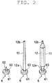
FIG. 2 is a perspective view of a tray, an empty bobbin, and a yarn supplying bobbin transported in the yarn winding system ofFIG. 1 ; -
FIG. 3 is a side view of a spinning unit of the yarn winding system ofFIG. 1 . -
FIG. 4 is a side view of a winding unit of the yarn winding system ofFIG. 1 ; -
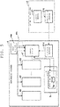
FIG. 5 is a block diagram illustrating a functional configuration of the yarn winding system ofFIG. 1 ; -
FIG. 6 is a flowchart illustrating an operation of the yarn winding system ofFIG. 1 ; -
FIG. 7 is a flowchart illustrating an operation of an automatic winder of a second embodiment of the present invention; and -
FIG. 8 is a flowchart illustrating the operation of the automatic winder of the second embodiment of the present invention. - A first embodiment of the present invention will be hereinafter described in detail with reference to the accompanying drawings. The same reference numerals are denoted on the same or corresponding portions throughout the drawings, and redundant description will be omitted.
- As illustrated in
FIG. 1 , ayarn winding system 1 includes aroving machine 2, aspinning machine 3, and anautomatic winder 4. Theroving machine 2 is adapted to produce a rove from a sliver, and wind the rove to form a roving bobbin. Thespinning machine 3 is adapted to produce a yarn from the rove, and wind the yarn to form ayarn supplying bobbin 11. Theautomatic winder 4 is adapted to wind the yarn from theyarn supplying bobbin 11 to form apackage 15. Theautomatic winder 4 includes a bobbin transferring device (bobbin transferring section) 5. Thebobbin transferring device 5 is adapted to transfer theyarn supplying bobbin 11 from thespinning machine 3 to theautomatic winder 4, and transfer an empty bobbin 12 (bobbin around which a yarn is not wound) from theautomatic winder 4 to thespinning machine 3. Thebobbin transferring device 5 includes a bobbin preparing device (bobbin preparing section) 7 and a remaining yarn processing device, and the like. Thebobbin preparing device 7 is adapted to carry out a preliminary preparation for theautomatic winder 4 to process the yarn of theyarn supplying bobbin 11. If the yarn remains on thebobbin 12 discharged from theyarn supplying bobbin 11, the remaining yarn processing device removes the yarn to obtain theempty bobbin 12. Thus, thebobbin transferring device 5 has a complex transportation path with many curves. - The
yarn supplying bobbin 11 and theempty bobbin 12 are respectively transferred while being set on atray 6. As illustrated inFIG. 2 , thetray 6 includes a circular plateshaped base portion 61, apin 62 that projects out toward an upper side from thebase portion 61, and an RF (Radio Frequency)tag 63 incorporated in thebase portion 61. When thepin 62 is inserted into abottom portion 12a of thebobbin 12, theyarn supplying bobbin 11 and theempty bobbin 12 are respectively set on thetray 6 with atop portion 12b of thebobbin 12 facing the upper side. The RF tag (recording section) 63 stores information relating to theyarn supplying bobbin 11 set on thetray 6. In theyarn winding system 1, the status of theyarn supplying bobbin 11 set on thetray 6 is managed by an RFID (Radio Frequency Identification: Identification by radio wave) technique. - As illustrated in
FIG. 1 , theroving machine 2 includes acontrol device 21 adapted to control the operation of theroving machine 2, and a plurality ofroving units 22 adapted to form the roving bobbin. Thecontrol device 21 includes adisplay section 21a such as a display, and anoperation section 21b such as input keys. Thedisplay section 21a displays an operational status of eachroving unit 22, and the like. Theoperation section 21b is provided for an operator to carry out setting of the operational conditions of eachroving unit 22, and the like. - The spinning
machine 3 includes acontrol device 31 adapted to control the operation of the spinningmachine 3, and a plurality of spinningunits 32 adapted to form theyarn supplying bobbin 11. Thecontrol device 31 includes adisplay section 31a such as a display, and anoperation section 31b such as input keys. Thedisplay section 31a displays an operational status of each spinningunit 32, and the like. Theoperation section 31b is provided for an operator to carry out setting of the operational conditions of each spinningunit 32, and the like. - As illustrated in
FIG. 3 , the spinningunit 32 includes adraft device 33 and atwist applying device 34. - The
draft device 33 includes a pair ofback rollers 33a, a pair ofmiddle rollers 33b, and a pair offront rollers 33c. The pair ofback rollers 33a, the pair ofmiddle rollers 33b, and the pair offront rollers 33c are each configured by a bottom roller and a top roller. An apron belt is provided on each roller configuring the pair ofmiddle rollers 33b. In thedraft device 33, therove 13 unwound from the roving bobbin is drafted by rotating the pair ofback rollers 33a, the pair ofmiddle rollers 33b, and the pair offront rollers 33c at a predetermined speed ratio. - The
twist applying device 34 includes aspindle shaft 35, aring rail 36, aring 37, and atraveler 38. Thespindle shaft 35 is adapted to hold thebottom portion 12a of thebobbin 12 with thetop portion 12b of thebobbin 12 facing the upper side, and rotate thebobbin 12. Thering rail 36 is movable in an axis line direction of thebobbin 12. Thering 37 is fixed to thering rail 36. Thetraveler 38 is supported by thering 37, and is movable along thering 37. - In the
twist applying device 34, therove 13 drafted by thedraft device 33 is inserted into a gap between thering 37 and thetraveler 38, and an end of therove 13 is fixed to thebobbin 12. Thespindle shaft 35 rotates thebobbin 12 in such a state, whereby thetraveler 38 moves along thering 37 as if being pulled by therove 13. In this case, thering rail 36 gradually moves from thebottom portion 12a side toward thetop portion 12b side while reciprocating within a predetermined range along the axis line direction of thebobbin 12. In thetwist applying device 34, the rotation of thetraveler 38 is delayed from the rotation of thebobbin 12 so that twists are applied to therove 13 and ayarn 14 is produced. Then, theyarn 14 is wound around thebobbin 12 to form theyarn supplying bobbin 11. - The spinning
machine 3 including a plurality of spinningunits 32 configured as above is configured as a so-called simultaneous doffing type. In other words, the spinningmachine 3 stocks a plurality ofempty bobbins 12 transferred from theautomatic winder 4 by thebobbin transferring device 5, simultaneously sets theempty bobbin 12 in each spinningunit 32, and simultaneously starts the winding of the yarn. When the winding of the yarn is completed in each spinningunit 32 and theyarn supplying bobbin 11 is formed, the spinningmachine 3 simultaneously doffs (doffing) all theyarn supplying bobbins 11. Then, the spinningmachine 3 extracts theempty bobbins 12 stocked in the meantime from thetray 6, and again simultaneously sets such empty bobbin in each spinningunit 32, and simultaneously sets the doffedyarn supplying bobbins 11 on thetray 6 instead. - As illustrated in
FIG. 1 , theautomatic winder 4 includes acontrol device 41 adapted to control the operation of theautomatic winder 4, a plurality of windingunits 42 adapted to formpackages 15, and thebobbin transferring device 5. Thecontrol device 41 includes adisplay section 41a such as a display, and anoperation section 41b such as input keys. Thedisplay section 41a displays an operational status of each windingunit 42, and the like. Theoperation section 41b is provided for an operator to carry out setting of the operational conditions of each windingunit 42, and the like. Thecontrol device 41 also controls the operation of thebobbin transferring device 5. - As illustrated in
FIG. 4 , the windingunit 42 includes a windingdevice 43, atension applying device 44, ayarn monitoring device 45, an upperyarn catching device 46, a loweryarn catching device 47, and ayarn joining device 48. - The winding
device 43 includes acradle 43a and a windingdrum 43b. Thecradle 43a supports thepackage 15. The windingdrum 43b rotates thepackage 15 while traversing theyarn 14. Theyarn 14 is thereby wound from theyarn supplying bobbin 11 set at a predetermined position to form thepackage 15. Thetension applying device 44 applies a predetermined tension on theyarn 14 travelling from theyarn supplying bobbin 11 to thepackage 15. - The
yarn monitoring device 45 is adapted to monitor the travellingyarn 14 to detect yarn defects (thickness abnormality of theyarn 14, mixing of foreign substance to theyarn 14, etc.) . When the yarn defect is detected, theyarn 14 is cut with a separately provided cutter. When theyarn 14 is cut, the upperyarn catching device 46 catches a yarn end of theyarn 14 from thepackage 15 and guides the yarn end to theyarn joining device 48. When theyarn 14 is cut, the loweryarn catching device 47 catches a yarn end of theyarn 14 from theyarn supplying bobbin 11 and guides the yarn end to theyarn joining device 48. Theyarn joining device 48 joins the yarn ends guided by the upperyarn catching device 46 and the loweryarn catching device 47. - As illustrated in
FIG. 1 , thebobbin transferring device 5 includes anRF writer 51. When theyarn supplying bobbin 11 is transferred from the spinningmachine 3 to theautomatic winder 4, theRF writer 51 writes information relating to the relevantyarn supplying bobbin 11 to theRF tag 63 of thetray 6 on which the relevantyarn supplying bobbin 11 is set. The information relating to theyarn supplying bobbin 11 includes unit identification information for specifying thespinning unit 32 that formed theyarn supplying bobbin 11, and doffing information (timing information) for specifying timing of simultaneous doffing. More specifically, the doffing information is information indicating the timing at which the doffing is carried out such as the time for which the simultaneous doffing is carried out, how many times doffing has been carried out from a time point set as a reference, or the like. TheRF writer 51 may be arranged at an exit in the transferring direction of theyarn supplying bobbin 11 of the spinningmachine 3. Furthermore, theRF writer 51 may be provided for everyspinning unit 32. - The information written on the
RF tag 63 by theRF writer 51 is read by an RF reader (reading section) 49 arranged on each windingunit 42, and transmitted to thecontrol device 41 of theautomatic winder 4 when theyarn supplying bobbin 11 is set on the windingunit 42 of theautomatic winder 4. Thecontrol device 41 then can specify thespinning unit 32 that formed the relevantyarn supplying bobbin 11 and the timing of simultaneous doffing with respect to theyarn supplying bobbin 11 set on the windingunit 42. - Next, a mechanism in which the
spinning machine 3 transmits the spinning information (to be described in detail later) to theautomatic winder 4, and theautomatic winder 4 controls the operation of the automatic winder 4 (i.e., operation of each windingunit 42 and the bobbin preparing device 7) based on the spinning information will be described with reference toFIGS. 5 and6 . - As illustrated in
FIG. 5 , the spinningmachine 3 includes a control device (generating section) 31 and atransmitting section 31c as a functional element for realizing the mechanism described above. Furthermore, theautomatic winder 4 includes a control device (control section) 41, each windingunit 42, thebobbin preparing device 7 arranged on thebobbin transferring device 5, anRF reader 7a arranged on thebobbin preparing device 7, and a receivingsection 41c. - The
control device 31 is an electronic control unit including a CPU (Central Processing Unit), a ROM (Read Only Memory), a RAM (Random Access Memory), and the like. Thecontrol device 31 loads a program stored in the ROM to the RAM and executes the program with the CPU to execute various types of controls. Thecontrol device 31 may be configured by a plurality of electronic control units. Thecontrol device 31 functions as a generating section that generates the spinning information including information relating to at least one of the processing status of the formation of theyarn supplying bobbin 11 and the completion condition of spinning of theyarn supplying bobbin 11. - The information relating to the processing status of the formation of the yarn supplying bobbin 11 (hereinafter referred to as "processing status information") is, for example, information indicating a remaining time until the
yarn supplying bobbins 11 are simultaneously doffed in the plurality of spinningunits 32 by the simultaneous doffing. Thecontrol device 31 refers to the setting relating to the monitoring of the operational status of each spinningunit 32 and the operation of each spinningunit 32, for example, to obtain the processing status information described above. - The information relating to the completion condition of spinning of the yarn supplying bobbin 11 (hereinafter referred to as "completion condition information") is, for example, information relating to the condition (doffing condition) to be satisfied when doffing the
yarn supplying bobbin 11 in each spinningunit 32. The completion condition information is, for example, information relating to a state of a winding end of the yarn in theyarn supplying bobbin 11. The information relating to the state of the winding end of the yarn is, for example, information indicating whether or not a so-called bunch winding process is performed, whether or not theyarn supplying bobbin 11 is formed in a half bobbin, or the like in the state of the winding end of the yarn in theyarn supplying bobbin 11. - In the present embodiment, by way of example, the
control device 31 generates data including the processing status information and the completion condition information described above, and the doffing information for specifying the timing at which theyarn supplying bobbin 11 is formed, as the spinning information, and transmits the data to theautomatic winder 4 through the transmittingsection 31c. Although the timing at which thecontrol device 31 generates the spinning information and transmits the spinning information to theautomatic winder 4 is arbitrary, in the present embodiment, thecontrol device 31 periodically generates the spinning information at a predetermined interval defined in advance and transmits the spinning information to theautomatic winder 4, by way of example. Theautomatic winder 4 thus can obtain the processing status of the spinningmachine 3 on a timely basis, and can appropriately control the winding speed of the windingunit 42 each time (to be described in detail later). - The transmitting
section 31c transmits the spinning information generated by thecontrol device 31 to theautomatic winder 4. The transmission by the transmittingsection 31c may be carried out in a wired manner by a cable and the like, or may be carried out in a wireless manner. When carrying out wireless transmission by the transmittingsection 31c, radio wave, infrared ray, or light may be adopted for a transmission medium. InFIG. 5 , the transmittingsection 31c is illustrated as an element separate from thecontrol device 31, but the transmittingsection 31c may be configured to be included in thecontrol device 31. That is, the transmittingsection 31c may be a communication function incorporated in thecontrol device 31. - The receiving
section 41c is adapted to receive the spinning information transmitted from the spinningmachine 3. The reception by the receivingsection 41c may be carried out in a wired manner by a cable and the like, or may be carried out in a wireless manner. When carrying out wireless reception by the receivingsection 41c, radio wave, infrared ray, or light may be adopted for a transmission medium. InFIG. 5 , the receivingsection 41c is illustrated as an element separate from thecontrol device 41, but the receivingsection 41c may be configured to be included in thecontrol device 41. That is, the receivingsection 41c may be a communication function incorporated in thecontrol device 41. - The
control device 41 is an electronic control unit including the CPU, the ROM, the RAM, and the like. Thecontrol device 41 loads a program stored in the ROM to the RAM, and executes the program with the CPU to execute various types of controls . Thecontrol device 41 may be configured by a plurality of electronic control units . Thecontrol device 41 controls the operation of theautomatic winder 4 based on the spinning information received by the receivingsection 41c. Specifically, thecontrol device 41 determines the operation of each windingunit 42 based on the spinning information, and transmits a control signal indicating the determined operation to each windingunit 42 on a timely basis to control the operation of each windingunit 42. - The
control device 41 determines the winding speed of when each windingunit 42 winds the yarn from theyarn supplying bobbin 11 based on the processing status information included in the spinning information, and controls the operation of each windingunit 42 so as to wind the yarn from theyarn supplying bobbin 11 at the determined winding speed. - As described above, the
yarn supplying bobbin 11 is transferred from the spinningmachine 3 to theautomatic winder 4, and theempty bobbin 12 is transferred from theautomatic winder 4 to the spinningmachine 3. It is to be noted that if a pace (supply pace) at which theyarn supplying bobbin 11 is transferred from the spinningmachine 3 to theautomatic winder 4 per unit time is slower than a pace (discharge pace) at which theempty bobbin 12 is transferred from theautomatic winder 4 to the spinningmachine 3 per unit time, this means that the process of theautomatic winder 4 has a margin. In other words, this means that the winding speed of each windingunit 42 can be reduced. On the other hand, if the supply pace is faster than the discharge pace, this means that the process of theautomatic winder 4 does not have a margin. In other words, the winding speed of each windingunit 42 needs to be increased in order to balance the processing speeds of the spinningmachine 3 and theautomatic winder 4. - The
control device 41 calculates the supply pace of theyarn supplying bobbin 11 based on the processing status information included in the spinning information, and determines the winding speed of each windingunit 42 so that the supply pace and the pace of the winding process in each winding unit 42 (i.e., discharge pace of the empty bobbin 12) are balanced. Thus, when the supply pace is faster than the discharge pace, thecontrol device 41 can balance the process of the spinningmachine 3 and the process of theautomatic winder 4 by increasing the winding speed of each windingunit 42. Furthermore, when the supply pace is slower than the discharge pace, thecontrol device 41 can enhance the winding quality (i.e., quality of package 15) in each windingunit 42 by reducing the winding speed of each windingunit 42. - Furthermore, the
control device 41 controls the preparatory operation of the bobbin with respect to theyarn supplying bobbin 11 in thebobbin preparing device 7 arranged on thebobbin transferring device 5 based on the information relating to the winding end of the yarn included in the spinning information. For example, thecontrol device 41 specifies whether or not the bunch winding process is carried out in theyarn supplying bobbin 11 from the information relating to the winding end of the yarn. When specified that the bunch winding process is carried out in theyarn supplying bobbin 11, thecontrol device 41 controls the operation of thebobbin preparing device 7 so as to omit the operations that become unnecessary when the bunch winding process is carried out (e.g., operations such as cutting of the yarn end of theyarn supplying bobbin 11 by a yarn end cutting device (not illustrated) arranged on thebobbin preparing device 7, suction of the yarn end of theyarn supplying bobbin 11 by a yarn end suction device (not illustrated) arranged on thebobbin preparing device 7, etc.). Thus, the useless operations can be prevented from being carried out in thebobbin preparing device 7. - For example, the
control device 41 specifies whether or not theyarn supplying bobbin 11 is formed in the half bobbin from the information relating to the winding end of the yarn. When specified that theyarn supplying bobbin 11 is formed to a half bobbin, thecontrol device 41 controls the operation of thebobbin preparing device 7 so that, for example, a search operation (operation for searching the yarn end of the yarn supplying bobbin 11) of the yarn end cutting device and the yarn end suction device described above is carried out within a range corresponding to the half bobbin (e.g., predetermined range on thebottom portion 12a side) . Thus, the search operation can be prevented from being carried out in a useless range, and the yarn end can be promptly found. The optimization of the operation of thebobbin preparing device 7 can be realized by controlling the preparatory operation of the bobbin in thebobbin preparing device 7 according to the state of the winding end of the yarn in theyarn supplying bobbin 11 as described above. - The completion condition of spinning of the
yarn supplying bobbin 11 may differ for every timing of simultaneous doffing in the spinningmachine 3. For example, the completion condition of spinning may be set so that the bunch winding process is carried out in theyarn supplying bobbin 11 in the simultaneous doffing at a first timing, and the bunch processing is not carried out in theyarn supplying bobbin 11 in the simultaneous doffing at a second timing after the first timing. The reason the bunch winding process is not carried out in theyarn supplying bobbin 11 in the simultaneous doffing at the second timing may include a case in which the rove wound around the roving bobbin set in the spinningmachine 3 is used up by multiple spinningunits 32, a case in which the doffing needs to be carried out in a halfway state due to the trouble of the spinningmachine 3, and the like. Theyarn supplying bobbins 11 formed at the first timing and the second timing, which have different completion conditions of spinning, may be mixed and transferred to thebobbin preparing device 7. In such a case, when carrying out the preparatory work with respect to theyarn supplying bobbin 11 formed at the first timing, thecontrol device 41 needs to control the operation of thebobbin preparing device 7 based on the completion condition information (i.e., completion condition information applied to theyarn supplying bobbin 11 formed at the first timing) included in first spinning information including the doffing information indicating the first timing. Similarly, when carrying out the preparatory work with respect to theyarn supplying bobbin 11 formed at the second timing, thecontrol device 41 needs to control the operation of thebobbin preparing device 7 based on the completion condition information (i.e., completion condition information applied to theyarn supplying bobbin 11 formed at the second timing) included in second spinning information including the doffing information indicating the second timing. Theautomatic winder 4 is configured to be able to realize such control. The mechanism will be described below. - First, the
control device 41 periodically receives the spinning information from the spinningmachine 3 through the receivingsection 41c, and accumulates the first spinning information including the doffing information indicating the first timing and the second spinning information including the doffing information indicating the second timing. When theyarn supplying bobbin 11 is supplied to thebobbin preparing device 7, theRF reader 7a arranged on thebobbin preparing device 7 reads the information written on theRF tag 63 provided on thetray 6 transferring theyarn supplying bobbin 11, and transmits the information to thecontrol device 41. Thecontrol device 41 thereby acquires the doffing information indicating the timing at which theyarn supplying bobbin 11 supplied to thebobbin preparing device 7 is formed. - Then, the
control device 41 extracts the spinning information including the doffing information that coincides with the doffing information (doffing information indicating the timing at which theyarn supplying bobbin 11 is formed, for example, information specifying how many times the doffing has been carried out until the relevantyarn supplying bobbin 11 is doffed) received from theRF reader 7a from the accumulated spinning information, and controls the operation of thebobbin preparing device 7 based on the spinning information. Specifically, when the doffing information received from theRF reader 7a indicates the first timing (e.g., first doffing), thecontrol device 41 controls the preparatory operation of the bobbin of thebobbin preparing device 7 based on the completion condition information included in the first spinning information. When the doffing information received from theRF reader 7a indicates the second timing (e.g., second doffing), thecontrol device 41 controls the preparatory operation of the bobbin of thebobbin preparing device 7 based on the completion condition information included in the second spinning information. Thus, the preparatory operation of the bobbin by thebobbin preparing device 7 can be appropriately controlled based on the completion condition of spinning (e.g., information relating to the winding end of the yarn such as whether or not the bunch winding process is carried out, whether or not theyarn supplying bobbin 11 is formed in the half bobbin, etc.) applied to theyarn supplying bobbin 11 supplied to thebobbin preparing device 7. - Next, the operation of the yarn winding system 1 (operation including the yarn winding method according to present embodiment) will be described with reference to
FIG. 6 . As illustrated inFIG. 6 , first, thecontrol device 31 of the spinningmachine 3 generates the spinning information including at least one of the processing status information or the completion condition information (step S1, generating step). Then, the transmittingsection 31c of the spinningmachine 3 transmits the spinning information generated in step S1 to the automatic winder 4 (step S2, transmitting step). - Then, the receiving
section 41c of theautomatic winder 4 receives the spinning information (step S3, receiving step). The spinning information received by the receivingsection 41c is provided to thecontrol device 41. Thecontrol device 41 then controls the winding speed of each windingunit 42 based on the processing status information included in the spinning information (step S4, controlling step). Specifically, thecontrol device 41 calculates the supply pace of theyarn supplying bobbin 11 based on the processing status information included in the spinning information, and determines the winding speed of each windingunit 42 so that the supply pace and the pace of the winding process in each winding unit 42 (i.e., discharge pace of the empty bobbin 12) are balanced. Thecontrol device 41 then controls the operation of each windingunit 42 to wind the yarn from theyarn supplying bobbin 11 at the determined winding speed. - Furthermore, when the
yarn supplying bobbin 11 is supplied to thebobbin preparing device 7, theRF reader 7a arranged on thebobbin preparing device 7 reads the doffing information written on theRF tag 63 provided on thetray 6 transferring theyarn supplying bobbin 11, and transmits the doffing information to the control device 41 (step S5). Then, thecontrol device 41 controls the preparatory operation of the bobbin by thebobbin preparing device 7 based on the spinning information including the doffing information that coincides with the doffing information received from theRF reader 7a (step S6, controlling step). Specifically, as described above, thecontrol device 41 controls the operation of thebobbin preparing device 7 based on, for example, the information relating to the winding end of the yarn of theyarn supplying bobbin 11 included in the spinning information. - A second embodiment of the present invention will now be described. In the second embodiment, the description on the configurations common with the first embodiment will be omitted.
- The
automatic winder 4 of the second embodiment further includes aninput section 100 and a notifyingsection 101. In the configuration in which thereceiving section 41c of theautomatic winder 4 cannot receive the spinning information from the spinningmachine 3, the operator can input the spinning information to theinput section 100. The configuration in which thereceiving section 41c of theautomatic winder 4 cannot receive the spinning information from the spinningmachine 3 includes, for example, a case in which thespinning machine 3 does not include the transmittingsection 31c for communicating with theautomatic winder 4, a case in which thespinning machine 3 includes the transmittingsection 31c but the communication function does not operate due to malfunction, and the like. - As illustrated in
FIG. 7 , the operator can input a doffing number (number ofyarn supplying bobbins 11 which can be supplied by the spinningmachine 3 in one doffing), and the doffing information (time point of next doffing, or time required for one doffing) to theinput section 10 as the spinning information (step S7). - The
control device 41 of theautomatic winder 4 calculates number of yarn supplying bobbins to be wound by the time point of the next doffing (target winding number) from the input information (step S8). The target winding number can be easily calculated by subtracting, from the doffing number, the number ofyarn supplying bobbins 11, in which the winding process is completed on the bobbin supplied by the previous doffing. - The
control device 41 then obtains the time required for the windingunit 42 to wind one yarn supplying bobbin 11 (yarn supplying bobbin processing time) from the winding information (step S9). The yarn supplying bobbin processing time can be obtained by counting the number of winding processed bobbins returned from theautomatic winder 4 to the spinning machine at a predetermined time interval. Furthermore, the yarn supplying bobbin processing time can also be obtained by counting the actual time required by the windingunit 42 to process the yarn supplying bobbin. Furthermore, in view of the yarn supplying bobbin processing time and the number of windingunits 42 arranged in theautomatic winder 4, thecontrol device 41 computes a time required to process theyarn supplying bobbin 11 of the target winding number (step S10). Thecontrol device 41 then calculates a time point at which the winding of the target winding number is finished (step S11), and compares it with the time point of the next doffing (step S12). - As illustrated in
FIG. 8 , when the time point at which the winding of the target winding number is finished is later than the time point of the next doffing (step S14), thecontrol device 41 increases the winding speed of the winding unit 42 (step S15). Furthermore, when the time point at which the winding of the target winding number is finished is considerably earlier than the time point of the next doffing (step S17), the control device reduces the winding speed of the winding unit 42 (step S18). Furthermore, when the time point at which the winding of the target winding number is finished is substantially the same time point as the time point of the next doffing (step S16), the control device does not change the winding speed of the windingunit 42. Thus, the optimization of the operation control of theautomatic winder 4 can be realized by controlling the operation of theautomatic winder 4 based on the spinning information input by the operator. Herein, "considerably early" means early by more than or equal to a predetermined time set as a threshold value. "Substantially the same time point" means early within the predetermined time. The time point referred to herein includes the concept such as "time", "the moment after predetermined time from the current time", and the like. - When changing the winding speed of the winding
unit 42, a restriction (fluctuation restriction) for preventing the winding state of thepackage 15 from greatly changing by the rapid speed change is preferably provided. For example, since the change in the winding state of thepackage 15 can be avoided by restricting the change in the winding speed to within ±10%, the quality of the package will not be downgraded. - Furthermore, the fluctuation restriction can be freely changed by the
input section 100. - The
control device 41 can be configured so as not to automatically change the speed when the time point at which the winding of the target winding number is finished is later than the time point of the next doffing or when the time point at which the winding of the target winding number is finished is considerably earlier than the time point of the next doffing, and notify the speed change to the operator by the notifyingsection 101. A specific example of the notifyingsection 101 includes a patrol lamp and the like. Furthermore, when theinput section 100 includes a liquid crystal display screen, a configuration for notifying the necessity of speed change as characters on the liquid crystal display screen may be adopted. According to such a configuration, the operator can freely set the winding speed intended by the operator. For example, if notified that the time point at which the winding of the target winding number is finished is considerably earlier than the time point of the next doffing when maintenance is to be performed on some windingunits 42 of the automatic winder, the operator can set the winding speed of theautomatic winder 4 to slow. Furthermore, instead of reducing the winding speed, the operator can stop the windingunits 42 to which maintenance is to be performed. The winding efficiency of theautomatic winder 4 is thereby lowered, but this can be canceled out with the time for which theautomatic winder 4 is in a stopped state when the time point at which the winding of the target winding number is finished is considerably earlier than the time point of the next doffing. According to such a configuration, the operator can have more options, and flexible response can be made. - In the second embodiment of the present invention, the
control device 41 calculates the time point at which the winding of the target winding number is finished from the time required to process the target winding number. Next, the winding speed of the windingunit 42 is increased when the time point at which the winding of the target winding number is finished is later than the time point of the next doffing, the winding speed of the windingunit 42 is reduced when the time point at which the winding of the target winding number is finished is earlier than the time point of the next doffing by greater than or equal to a predetermined time, and the winding speed of the windingunit 42 is not changed when the time point at which the winding of the target winding number is finished is the same time point as the time point of the next doffing or earlier within a predetermined time. - A third embodiment of the present invention will now be described. In the third embodiment, description on the configurations common with the first embodiment and the second embodiment will be omitted.
- In the third embodiment, the receiving
section 41c of theautomatic winder 4 is configured to receive only the fact that the doffing is executed from the transmittingsection 31c of the spinningmachine 3. Even in thegeneral spinning machine 3 that does not have the function of transmitting the processing status information, the completion condition information, or the doffing information relating to the time until the next doffing, only the fact that the doffing is executed (doffing execution signal) can be transmitted. In the present embodiment, thecontrol device 41 of theautomatic winder 4 calculates the doffing information (time point of the next doffing or time required for one doffing) from the doffing execution signals received by the receivingsection 41c in the past. The doffing number (number ofyarn supplying bobbins 11 which can be supplied by the spinningmachine 3 in one doffing) is input from theinput section 100 by the operator. That is, in the case of the present embodiment, the receivingsection 41c also functions as the input section. When the time point at which the winding of the target winding number is finished is later than the calculated time point of the next doffing, thecontrol device 41 increases the winding speed of the windingunit 42. Furthermore, when the time point at which the winding of the target winding number is finished is considerably earlier than the calculated time point of the next doffing, the control device reduces the winding speed of the windingunit 42. The optimization of the operation control of theautomatic winder 4 can be realized by controlling the operation of theautomatic winder 4 based on the spinning information input by the operator. - Three embodiments of the present invention have been described above, but the present invention is not limited to such embodiments. For example, the transmission of the spinning information from the spinning
machine 3 to theautomatic winder 4 may not necessarily be carried out directly between the spinningmachine 3 and theautomatic winder 4, and for example, may be carried out via a predetermined relay device. In the embodiment described above, an example of controlling the operation (winding speed) of each windingunit 42 based on the processing status information has been described, but thecontrol device 41 may control the operation of thebobbin preparing device 7 based on the processing status information. Similarly, in the embodiment described above, an example of controlling the preparatory operation of thebobbin preparing device 7 based on the completion condition information has been described, but thecontrol device 41 may control the operation of each windingunit 42 based on the completion condition information.
Claims (11)
- An automatic winder (4) including a plurality of winding units (42) each adapted to wind a yarn from a yarn supplying bobbin (11) formed by a spinning machine (3) to form a package (15), the automatic winder (4) characterized by comprising:an input section (100) adapted to input spinning information including information relating to at least one of a processing status of formation of the yarn supplying bobbin (11) and a doffing execution signal; anda control section (41) adapted to determine a winding speed of when the winding unit (42) winds a yarn from the yarn supplying bobbin (11) based on the spinning information input by the input section (100) .
- The automatic winder (4) according to claim 1, characterized in that the control section (41) is adapted to control an operation of the winding unit (42) to wind the yarn from the yarn supplying bobbin (11) at the determined winding speed based on the information relating to the processing status of the formation of the yarn supplying bobbin (11).
- The automatic winder (4) according to claim 1 or 2, characterized in that
the control section (41) is adapted to:- obtain a time point of next doffing of the spinning machine (3) based on the information relating to the processing status of the formation of the yarn supplying bobbin (11),- obtain a yarn supplying bobbin processing time, which is a time required for the winding unit (42) to wind one yarn supplying bobbin (11), based on a target winding number, which is a number of yarn supplying bobbins (11) to be wound by the time point of the next doffing, and- calculate a time required to process the target winding number to determine a winding speed of when the winding unit (42) winds the yarn from the yarn supplying bobbin (11). - The automatic winder (4) according to claim 3, characterized in that
the control section (41) is adapted to:- calculate a time point at which winding of the target winding number is finished from the time required to process the target winding number,- increase the winding speed of the winding unit (42) when the time point at which the winding of the target winding number is finished is later than the time point of the next doffing,- reduce the winding speed of the winding unit (42) when the time point at which the winding of the target winding number is finished is earlier than the time point of the next doffing by greater than or equal to a predetermined time, and- not to change the winding speed of the winding unit (42) when the time point at which the winding of the target winding number is finished is the same time point as the time point of the next doffing or earlier within the predetermined time. - The automatic winder (4) according to claim 1, characterized in that
the control section (41) is adapted to:- calculate doffing information based on the doffing execution signal serving as the spinning information input by the input section (100), and- determine the winding speed of when the winding unit (42) winds a yarn from the yarn supplying bobbin (11) based on the calculated doffing information. - The automatic winder (4) according to claim 5, characterized in that
the control section (41) is adapted to:- obtain a time point of next doffing of the spinning machine (3) based on the calculated doffing information,- obtain a yarn supplying bobbin processing time, which is a time required for the winding unit (42) to wind one yarn supplying bobbin (11), based on a target winding number, which is a number of yarn supplying bobbins (11) to be wound by the time point of the next doffing, and- calculate a time required to process the target winding number to determine a winding speed of when the winding unit (42) winds the yarn from the yarn supplying bobbin (11). - The automatic winder (4) according to claim 6, characterized in that
the control section (41) is adapted to:- calculate a time point at which winding of the target winding number is finished from the time required to process the target winding number,- increase the winding speed of the winding unit (42) when the time point at which the winding of the target winding number is finished is later than the time point of the next doffing,- reduce the winding speed of the winding unit (42) when the time point at which the winding of the target winding number is finished is earlier than the time point of the next doffing by greater than or equal to a predetermined time, and- not to change the winding speed of the winding unit (42) when the time point at which the winding of the target winding number is finished is the same time point as the time point of the next doffing or earlier within the predetermined time. - The automatic winder (4) according to claim 4 or 7, characterized in that the control section (41) is adapted to change the winding speed of the winding unit (42) within a range of a fluctuation restriction that restricts a changing range of the winding speed.
- The automatic winder (4) according to claim 8, characterized in that the fluctuation restriction is changeable by the input section (100) .
- A winding speed control method for an automatic winder (4), the method comprising:a first step of obtaining a time point of next doffing of a spinning machine (3) based on information relating to a processing status of formation of a yarn supplying bobbin (11);a second step of calculating a target winding number, which is a number of yarn supplying bobbins (11) to be wound by the time point of the next doffing;a third step of obtaining a yarn supplying bobbin processing time, which is a time required for the winding unit (42) to wind one yarn supplying bobbin (11); anda fourth step of calculating a time required to process the target winding number to determine a winding speed of when the winding unit (42) winds the yarn from the yarn supplying bobbin (11).
- The winding speed control method for the automatic winder (4) according to claim 10, characterized in that
in the fourth step, a time point at which winding of the target winding number is finished is calculated from the time required to process the target winding number,
the winding speed of the winding unit (42) is increased when the time point at which the winding of the target winding number is finished is later than the time point of the next doffing,
the winding speed of the winding unit (42) is reduced when the time point at which the winding of the target winding number is finished is earlier than the time point of the next doffing by greater than or equal to a predetermined time, and
the winding speed of the winding unit (42) is not changed when the time point at which the winding of the target winding number is finished is the same time point as the time point of the next doffing or earlier within the predetermined time.
Applications Claiming Priority (1)
| Application Number | Priority Date | Filing Date | Title |
|---|---|---|---|
| JP2016234996A JP2018090375A (en) | 2016-12-02 | 2016-12-02 | Automatic winder, and winding speed control method for automatic winder |
Publications (2)
| Publication Number | Publication Date |
|---|---|
| EP3333109A1 true EP3333109A1 (en) | 2018-06-13 |
| EP3333109B1 EP3333109B1 (en) | 2022-06-29 |
Family
ID=60452535
Family Applications (1)
| Application Number | Title | Priority Date | Filing Date |
|---|---|---|---|
| EP17203581.8A Active EP3333109B1 (en) | 2016-12-02 | 2017-11-24 | Automatic winder and winding speed control method of automatic winder |
Country Status (3)
| Country | Link |
|---|---|
| EP (1) | EP3333109B1 (en) |
| JP (1) | JP2018090375A (en) |
| CN (1) | CN108147207B (en) |
Cited By (2)
| Publication number | Priority date | Publication date | Assignee | Title |
|---|---|---|---|---|
| EP4253618A1 (en) * | 2022-03-29 | 2023-10-04 | Rieter Automatic Winder GmbH | Method and device for operating an automatic cross-winding machine connected to a ring spinning machine by a bobbin and bobbin transport system |
| CN117246609A (en) * | 2023-11-15 | 2023-12-19 | 浙江恒逸石化有限公司 | Silk spindle coding method, device, electronic equipment and storage medium |
Families Citing this family (2)
| Publication number | Priority date | Publication date | Assignee | Title |
|---|---|---|---|---|
| CN111646294B (en) * | 2019-03-04 | 2022-05-27 | 铜陵松宝智能装备股份有限公司 | Multi-variety cop control method for bobbin winder |
| JP2021001405A (en) * | 2019-06-19 | 2021-01-07 | 株式会社豊田自動織機 | Yarn winding system |
Citations (6)
| Publication number | Priority date | Publication date | Assignee | Title |
|---|---|---|---|---|
| CH668414A5 (en) * | 1983-01-05 | 1988-12-30 | Murata Machinery Ltd | Bobbin transport system |
| JPH01183530A (en) * | 1988-01-08 | 1989-07-21 | Murata Mach Ltd | Spinning winder |
| EP0511158A1 (en) * | 1991-04-22 | 1992-10-28 | Maschinenfabrik Rieter Ag | Method and apparatus for transferring cops and bobbin tubes between a ring spinning machine and an associated winding machine |
| JPH0676177B2 (en) | 1989-07-26 | 1994-09-28 | 村田機械株式会社 | Tray transport system |
| EP2028302A2 (en) * | 2007-08-17 | 2009-02-25 | Oerlikon Textile GmbH & Co. KG | Spinning unit |
| EP3305953A1 (en) * | 2015-06-05 | 2018-04-11 | Murata Machinery, Ltd. | Yarn winding system, spinning frame, automatic winder, and yarn winding method |
Family Cites Families (6)
| Publication number | Priority date | Publication date | Assignee | Title |
|---|---|---|---|---|
| US4660369A (en) * | 1984-01-21 | 1987-04-28 | Murata Kikai Kabushiki Kaisha | Bobbin transporting system |
| DE19538284A1 (en) * | 1995-10-16 | 1997-04-17 | Schlafhorst & Co W | Cops conveyor system for automatic bobbin winder |
| JP2006241616A (en) * | 2005-03-01 | 2006-09-14 | Murata Mach Ltd | Air spinning machine and spinning system |
| CN201627029U (en) * | 2010-01-25 | 2010-11-10 | 马佐里(东台)纺机有限公司 | Bobbin conveying device used for collective doffing of spinning machine |
| DE102012103282A1 (en) * | 2012-04-16 | 2013-10-17 | Maschinenfabrik Rieter Ag | Winding machine and method for operating a winder |
| JP2014227249A (en) * | 2013-05-21 | 2014-12-08 | 村田機械株式会社 | Yarn winder |
-
2016
- 2016-12-02 JP JP2016234996A patent/JP2018090375A/en active Pending
-
2017
- 2017-11-24 EP EP17203581.8A patent/EP3333109B1/en active Active
- 2017-11-28 CN CN201711213825.1A patent/CN108147207B/en active Active
Patent Citations (6)
| Publication number | Priority date | Publication date | Assignee | Title |
|---|---|---|---|---|
| CH668414A5 (en) * | 1983-01-05 | 1988-12-30 | Murata Machinery Ltd | Bobbin transport system |
| JPH01183530A (en) * | 1988-01-08 | 1989-07-21 | Murata Mach Ltd | Spinning winder |
| JPH0676177B2 (en) | 1989-07-26 | 1994-09-28 | 村田機械株式会社 | Tray transport system |
| EP0511158A1 (en) * | 1991-04-22 | 1992-10-28 | Maschinenfabrik Rieter Ag | Method and apparatus for transferring cops and bobbin tubes between a ring spinning machine and an associated winding machine |
| EP2028302A2 (en) * | 2007-08-17 | 2009-02-25 | Oerlikon Textile GmbH & Co. KG | Spinning unit |
| EP3305953A1 (en) * | 2015-06-05 | 2018-04-11 | Murata Machinery, Ltd. | Yarn winding system, spinning frame, automatic winder, and yarn winding method |
Cited By (4)
| Publication number | Priority date | Publication date | Assignee | Title |
|---|---|---|---|---|
| EP4253618A1 (en) * | 2022-03-29 | 2023-10-04 | Rieter Automatic Winder GmbH | Method and device for operating an automatic cross-winding machine connected to a ring spinning machine by a bobbin and bobbin transport system |
| CN117246609A (en) * | 2023-11-15 | 2023-12-19 | 浙江恒逸石化有限公司 | Silk spindle coding method, device, electronic equipment and storage medium |
| CN117246609B (en) * | 2023-11-15 | 2024-01-30 | 浙江恒逸石化有限公司 | Silk spindle coding method, device, electronic equipment and storage medium |
| US12391512B2 (en) | 2023-11-15 | 2025-08-19 | Zhejiang Hengyi Petrochemical Co., Ltd. | Yarn spindle coding method, electronic device and storage medium |
Also Published As
| Publication number | Publication date |
|---|---|
| CN108147207A (en) | 2018-06-12 |
| JP2018090375A (en) | 2018-06-14 |
| EP3333109B1 (en) | 2022-06-29 |
| CN108147207B (en) | 2021-11-30 |
Similar Documents
| Publication | Publication Date | Title |
|---|---|---|
| EP3305953B1 (en) | Yarn winding system, automatic winder, and yarn winding method | |
| EP3333109B1 (en) | Automatic winder and winding speed control method of automatic winder | |
| EP3305701B1 (en) | Yarn winding system, automatic winder and yarn winding method | |
| CN107531444B (en) | Yarn winding system, automatic winder, worst spinning machine, and yarn winding method | |
| EP3549893B1 (en) | Automatic winder, yarn winding system, and yarn winding method | |
| EP3409626B1 (en) | Productivity display control device, method thereof, and automatic winder | |
| JP2021525838A (en) | Automatic ring spinning equipment and how to operate the ring spinning equipment automatically | |
| WO2023066544A1 (en) | An electronic device for adjusting operational parameters of a winding machine of a spinning mill and a method for adjusting the same | |
| CN104176558A (en) | Yarn winding machine | |
| JP2018177449A (en) | Management apparatus and yarn winding system | |
| EP3305951B1 (en) | Spinning machine, yarn winding system, and method for manufacturing yarn supply bobbin | |
| CN107614407B (en) | Yarn winding system, automatic winder, spinning machine, and yarn winding method | |
| JP2019052045A (en) | Textile machine, management device, yarn winding system and yarn winding method | |
| US20250236994A1 (en) | An electronic device for locating a functional disorder within a spinning and winding section of a spinning mill and a method for locating the same |
Legal Events
| Date | Code | Title | Description |
|---|---|---|---|
| PUAI | Public reference made under article 153(3) epc to a published international application that has entered the european phase |
Free format text: ORIGINAL CODE: 0009012 |
|
| STAA | Information on the status of an ep patent application or granted ep patent |
Free format text: STATUS: THE APPLICATION HAS BEEN PUBLISHED |
|
| AK | Designated contracting states |
Kind code of ref document: A1 Designated state(s): AL AT BE BG CH CY CZ DE DK EE ES FI FR GB GR HR HU IE IS IT LI LT LU LV MC MK MT NL NO PL PT RO RS SE SI SK SM TR |
|
| AX | Request for extension of the european patent |
Extension state: BA ME |
|
| STAA | Information on the status of an ep patent application or granted ep patent |
Free format text: STATUS: REQUEST FOR EXAMINATION WAS MADE |
|
| 17P | Request for examination filed |
Effective date: 20180926 |
|
| RBV | Designated contracting states (corrected) |
Designated state(s): AL AT BE BG CH CY CZ DE DK EE ES FI FR GB GR HR HU IE IS IT LI LT LU LV MC MK MT NL NO PL PT RO RS SE SI SK SM TR |
|
| STAA | Information on the status of an ep patent application or granted ep patent |
Free format text: STATUS: EXAMINATION IS IN PROGRESS |
|
| 17Q | First examination report despatched |
Effective date: 20191111 |
|
| GRAP | Despatch of communication of intention to grant a patent |
Free format text: ORIGINAL CODE: EPIDOSNIGR1 |
|
| STAA | Information on the status of an ep patent application or granted ep patent |
Free format text: STATUS: GRANT OF PATENT IS INTENDED |
|
| INTG | Intention to grant announced |
Effective date: 20220317 |
|
| GRAS | Grant fee paid |
Free format text: ORIGINAL CODE: EPIDOSNIGR3 |
|
| GRAA | (expected) grant |
Free format text: ORIGINAL CODE: 0009210 |
|
| STAA | Information on the status of an ep patent application or granted ep patent |
Free format text: STATUS: THE PATENT HAS BEEN GRANTED |
|
| AK | Designated contracting states |
Kind code of ref document: B1 Designated state(s): AL AT BE BG CH CY CZ DE DK EE ES FI FR GB GR HR HU IE IS IT LI LT LU LV MC MK MT NL NO PL PT RO RS SE SI SK SM TR |
|
| REG | Reference to a national code |
Ref country code: CH Ref legal event code: EP |
|
| REG | Reference to a national code |
Ref country code: AT Ref legal event code: REF Ref document number: 1501239 Country of ref document: AT Kind code of ref document: T Effective date: 20220715 |
|
| REG | Reference to a national code |
Ref country code: IE Ref legal event code: FG4D |
|
| REG | Reference to a national code |
Ref country code: DE Ref legal event code: R096 Ref document number: 602017058962 Country of ref document: DE |
|
| REG | Reference to a national code |
Ref country code: LT Ref legal event code: MG9D |
|
| PG25 | Lapsed in a contracting state [announced via postgrant information from national office to epo] |
Ref country code: SE Free format text: LAPSE BECAUSE OF FAILURE TO SUBMIT A TRANSLATION OF THE DESCRIPTION OR TO PAY THE FEE WITHIN THE PRESCRIBED TIME-LIMIT Effective date: 20220629 Ref country code: NO Free format text: LAPSE BECAUSE OF FAILURE TO SUBMIT A TRANSLATION OF THE DESCRIPTION OR TO PAY THE FEE WITHIN THE PRESCRIBED TIME-LIMIT Effective date: 20220929 Ref country code: LT Free format text: LAPSE BECAUSE OF FAILURE TO SUBMIT A TRANSLATION OF THE DESCRIPTION OR TO PAY THE FEE WITHIN THE PRESCRIBED TIME-LIMIT Effective date: 20220629 Ref country code: HR Free format text: LAPSE BECAUSE OF FAILURE TO SUBMIT A TRANSLATION OF THE DESCRIPTION OR TO PAY THE FEE WITHIN THE PRESCRIBED TIME-LIMIT Effective date: 20220629 Ref country code: GR Free format text: LAPSE BECAUSE OF FAILURE TO SUBMIT A TRANSLATION OF THE DESCRIPTION OR TO PAY THE FEE WITHIN THE PRESCRIBED TIME-LIMIT Effective date: 20220930 Ref country code: FI Free format text: LAPSE BECAUSE OF FAILURE TO SUBMIT A TRANSLATION OF THE DESCRIPTION OR TO PAY THE FEE WITHIN THE PRESCRIBED TIME-LIMIT Effective date: 20220629 Ref country code: BG Free format text: LAPSE BECAUSE OF FAILURE TO SUBMIT A TRANSLATION OF THE DESCRIPTION OR TO PAY THE FEE WITHIN THE PRESCRIBED TIME-LIMIT Effective date: 20220929 |
|
| REG | Reference to a national code |
Ref country code: NL Ref legal event code: MP Effective date: 20220629 |
|
| REG | Reference to a national code |
Ref country code: AT Ref legal event code: MK05 Ref document number: 1501239 Country of ref document: AT Kind code of ref document: T Effective date: 20220629 |
|
| PG25 | Lapsed in a contracting state [announced via postgrant information from national office to epo] |
Ref country code: RS Free format text: LAPSE BECAUSE OF FAILURE TO SUBMIT A TRANSLATION OF THE DESCRIPTION OR TO PAY THE FEE WITHIN THE PRESCRIBED TIME-LIMIT Effective date: 20220629 Ref country code: LV Free format text: LAPSE BECAUSE OF FAILURE TO SUBMIT A TRANSLATION OF THE DESCRIPTION OR TO PAY THE FEE WITHIN THE PRESCRIBED TIME-LIMIT Effective date: 20220629 |
|
| PG25 | Lapsed in a contracting state [announced via postgrant information from national office to epo] |
Ref country code: NL Free format text: LAPSE BECAUSE OF FAILURE TO SUBMIT A TRANSLATION OF THE DESCRIPTION OR TO PAY THE FEE WITHIN THE PRESCRIBED TIME-LIMIT Effective date: 20220629 |
|
| PG25 | Lapsed in a contracting state [announced via postgrant information from national office to epo] |
Ref country code: SM Free format text: LAPSE BECAUSE OF FAILURE TO SUBMIT A TRANSLATION OF THE DESCRIPTION OR TO PAY THE FEE WITHIN THE PRESCRIBED TIME-LIMIT Effective date: 20220629 Ref country code: SK Free format text: LAPSE BECAUSE OF FAILURE TO SUBMIT A TRANSLATION OF THE DESCRIPTION OR TO PAY THE FEE WITHIN THE PRESCRIBED TIME-LIMIT Effective date: 20220629 Ref country code: RO Free format text: LAPSE BECAUSE OF FAILURE TO SUBMIT A TRANSLATION OF THE DESCRIPTION OR TO PAY THE FEE WITHIN THE PRESCRIBED TIME-LIMIT Effective date: 20220629 Ref country code: PT Free format text: LAPSE BECAUSE OF FAILURE TO SUBMIT A TRANSLATION OF THE DESCRIPTION OR TO PAY THE FEE WITHIN THE PRESCRIBED TIME-LIMIT Effective date: 20221031 Ref country code: ES Free format text: LAPSE BECAUSE OF FAILURE TO SUBMIT A TRANSLATION OF THE DESCRIPTION OR TO PAY THE FEE WITHIN THE PRESCRIBED TIME-LIMIT Effective date: 20220629 Ref country code: EE Free format text: LAPSE BECAUSE OF FAILURE TO SUBMIT A TRANSLATION OF THE DESCRIPTION OR TO PAY THE FEE WITHIN THE PRESCRIBED TIME-LIMIT Effective date: 20220629 Ref country code: AT Free format text: LAPSE BECAUSE OF FAILURE TO SUBMIT A TRANSLATION OF THE DESCRIPTION OR TO PAY THE FEE WITHIN THE PRESCRIBED TIME-LIMIT Effective date: 20220629 |
|
| PG25 | Lapsed in a contracting state [announced via postgrant information from national office to epo] |
Ref country code: PL Free format text: LAPSE BECAUSE OF FAILURE TO SUBMIT A TRANSLATION OF THE DESCRIPTION OR TO PAY THE FEE WITHIN THE PRESCRIBED TIME-LIMIT Effective date: 20220629 Ref country code: IS Free format text: LAPSE BECAUSE OF FAILURE TO SUBMIT A TRANSLATION OF THE DESCRIPTION OR TO PAY THE FEE WITHIN THE PRESCRIBED TIME-LIMIT Effective date: 20221029 |
|
| REG | Reference to a national code |
Ref country code: DE Ref legal event code: R097 Ref document number: 602017058962 Country of ref document: DE |
|
| PG25 | Lapsed in a contracting state [announced via postgrant information from national office to epo] |
Ref country code: AL Free format text: LAPSE BECAUSE OF FAILURE TO SUBMIT A TRANSLATION OF THE DESCRIPTION OR TO PAY THE FEE WITHIN THE PRESCRIBED TIME-LIMIT Effective date: 20220629 |
|
| PG25 | Lapsed in a contracting state [announced via postgrant information from national office to epo] |
Ref country code: DK Free format text: LAPSE BECAUSE OF FAILURE TO SUBMIT A TRANSLATION OF THE DESCRIPTION OR TO PAY THE FEE WITHIN THE PRESCRIBED TIME-LIMIT Effective date: 20220629 Ref country code: CZ Free format text: LAPSE BECAUSE OF FAILURE TO SUBMIT A TRANSLATION OF THE DESCRIPTION OR TO PAY THE FEE WITHIN THE PRESCRIBED TIME-LIMIT Effective date: 20220629 |
|
| PLBE | No opposition filed within time limit |
Free format text: ORIGINAL CODE: 0009261 |
|
| STAA | Information on the status of an ep patent application or granted ep patent |
Free format text: STATUS: NO OPPOSITION FILED WITHIN TIME LIMIT |
|
| 26N | No opposition filed |
Effective date: 20230330 |
|
| PG25 | Lapsed in a contracting state [announced via postgrant information from national office to epo] |
Ref country code: MC Free format text: LAPSE BECAUSE OF FAILURE TO SUBMIT A TRANSLATION OF THE DESCRIPTION OR TO PAY THE FEE WITHIN THE PRESCRIBED TIME-LIMIT Effective date: 20220629 |
|
| REG | Reference to a national code |
Ref country code: CH Ref legal event code: PL |
|
| GBPC | Gb: european patent ceased through non-payment of renewal fee |
Effective date: 20221124 |
|
| REG | Reference to a national code |
Ref country code: BE Ref legal event code: MM Effective date: 20221130 |
|
| PG25 | Lapsed in a contracting state [announced via postgrant information from national office to epo] |
Ref country code: LI Free format text: LAPSE BECAUSE OF NON-PAYMENT OF DUE FEES Effective date: 20221130 Ref country code: CH Free format text: LAPSE BECAUSE OF NON-PAYMENT OF DUE FEES Effective date: 20221130 |
|
| PG25 | Lapsed in a contracting state [announced via postgrant information from national office to epo] |
Ref country code: SI Free format text: LAPSE BECAUSE OF FAILURE TO SUBMIT A TRANSLATION OF THE DESCRIPTION OR TO PAY THE FEE WITHIN THE PRESCRIBED TIME-LIMIT Effective date: 20220629 Ref country code: LU Free format text: LAPSE BECAUSE OF NON-PAYMENT OF DUE FEES Effective date: 20221124 |
|
| PG25 | Lapsed in a contracting state [announced via postgrant information from national office to epo] |
Ref country code: IE Free format text: LAPSE BECAUSE OF NON-PAYMENT OF DUE FEES Effective date: 20221124 Ref country code: GB Free format text: LAPSE BECAUSE OF NON-PAYMENT OF DUE FEES Effective date: 20221124 |
|
| PG25 | Lapsed in a contracting state [announced via postgrant information from national office to epo] |
Ref country code: FR Free format text: LAPSE BECAUSE OF NON-PAYMENT OF DUE FEES Effective date: 20221130 Ref country code: BE Free format text: LAPSE BECAUSE OF NON-PAYMENT OF DUE FEES Effective date: 20221130 |
|
| PG25 | Lapsed in a contracting state [announced via postgrant information from national office to epo] |
Ref country code: HU Free format text: LAPSE BECAUSE OF FAILURE TO SUBMIT A TRANSLATION OF THE DESCRIPTION OR TO PAY THE FEE WITHIN THE PRESCRIBED TIME-LIMIT; INVALID AB INITIO Effective date: 20171124 |
|
| PG25 | Lapsed in a contracting state [announced via postgrant information from national office to epo] |
Ref country code: CY Free format text: LAPSE BECAUSE OF FAILURE TO SUBMIT A TRANSLATION OF THE DESCRIPTION OR TO PAY THE FEE WITHIN THE PRESCRIBED TIME-LIMIT Effective date: 20220629 |
|
| PG25 | Lapsed in a contracting state [announced via postgrant information from national office to epo] |
Ref country code: MK Free format text: LAPSE BECAUSE OF FAILURE TO SUBMIT A TRANSLATION OF THE DESCRIPTION OR TO PAY THE FEE WITHIN THE PRESCRIBED TIME-LIMIT Effective date: 20220629 |
|
| PG25 | Lapsed in a contracting state [announced via postgrant information from national office to epo] |
Ref country code: MT Free format text: LAPSE BECAUSE OF FAILURE TO SUBMIT A TRANSLATION OF THE DESCRIPTION OR TO PAY THE FEE WITHIN THE PRESCRIBED TIME-LIMIT Effective date: 20220629 |
|
| PG25 | Lapsed in a contracting state [announced via postgrant information from national office to epo] |
Ref country code: BG Free format text: LAPSE BECAUSE OF FAILURE TO SUBMIT A TRANSLATION OF THE DESCRIPTION OR TO PAY THE FEE WITHIN THE PRESCRIBED TIME-LIMIT Effective date: 20220629 |
|
| PG25 | Lapsed in a contracting state [announced via postgrant information from national office to epo] |
Ref country code: BG Free format text: LAPSE BECAUSE OF FAILURE TO SUBMIT A TRANSLATION OF THE DESCRIPTION OR TO PAY THE FEE WITHIN THE PRESCRIBED TIME-LIMIT Effective date: 20220629 |
|
| PGFP | Annual fee paid to national office [announced via postgrant information from national office to epo] |
Ref country code: DE Payment date: 20241022 Year of fee payment: 8 |
|
| PGFP | Annual fee paid to national office [announced via postgrant information from national office to epo] |
Ref country code: IT Payment date: 20241022 Year of fee payment: 8 |
|
| PG25 | Lapsed in a contracting state [announced via postgrant information from national office to epo] |
Ref country code: TR Free format text: LAPSE BECAUSE OF FAILURE TO SUBMIT A TRANSLATION OF THE DESCRIPTION OR TO PAY THE FEE WITHIN THE PRESCRIBED TIME-LIMIT Effective date: 20220629 |