EP3333009B1 - System zum wiederaufladen eines energiespeichers eines elektrofahrzeugs - Google Patents
System zum wiederaufladen eines energiespeichers eines elektrofahrzeugs Download PDFInfo
- Publication number
- EP3333009B1 EP3333009B1 EP17198756.3A EP17198756A EP3333009B1 EP 3333009 B1 EP3333009 B1 EP 3333009B1 EP 17198756 A EP17198756 A EP 17198756A EP 3333009 B1 EP3333009 B1 EP 3333009B1
- Authority
- EP
- European Patent Office
- Prior art keywords
- accumulator
- voltage
- converter unit
- converter
- switch
- Prior art date
- Legal status (The legal status is an assumption and is not a legal conclusion. Google has not performed a legal analysis and makes no representation as to the accuracy of the status listed.)
- Active
Links
Images







Classifications
-
- H—ELECTRICITY
- H02—GENERATION; CONVERSION OR DISTRIBUTION OF ELECTRIC POWER
- H02J—ELECTRIC POWER NETWORKS; CIRCUIT ARRANGEMENTS OR SYSTEMS FOR SUPPLYING OR DISTRIBUTING ELECTRIC POWER; SYSTEMS FOR STORING ELECTRIC ENERGY
- H02J7/00—Circuit arrangements for charging or discharging batteries or for supplying loads from batteries
- H02J7/60—Circuit arrangements for charging or discharging batteries or for supplying loads from batteries including safety or protection arrangements
- H02J7/68—Circuit arrangements for charging or discharging batteries or for supplying loads from batteries including safety or protection arrangements using circuits for correcting or protecting against reverse-polarity
-
- H—ELECTRICITY
- H02—GENERATION; CONVERSION OR DISTRIBUTION OF ELECTRIC POWER
- H02J—ELECTRIC POWER NETWORKS; CIRCUIT ARRANGEMENTS OR SYSTEMS FOR SUPPLYING OR DISTRIBUTING ELECTRIC POWER; SYSTEMS FOR STORING ELECTRIC ENERGY
- H02J7/00—Circuit arrangements for charging or discharging batteries or for supplying loads from batteries
- H02J7/40—Circuit arrangements for charging or discharging batteries or for supplying loads from batteries characterised by the exchange of charge or discharge related data
- H02J7/443—Circuit arrangements for charging or discharging batteries or for supplying loads from batteries characterised by the exchange of charge or discharge related data using passive battery identification means, e.g. resistors or capacitors
- H02J7/445—Circuit arrangements for charging or discharging batteries or for supplying loads from batteries characterised by the exchange of charge or discharge related data using passive battery identification means, e.g. resistors or capacitors in response to measured battery parameters, e.g. voltage, current or temperature profile
-
- B—PERFORMING OPERATIONS; TRANSPORTING
- B60—VEHICLES IN GENERAL
- B60L—PROPULSION OF ELECTRICALLY-PROPELLED VEHICLES; SUPPLYING ELECTRIC POWER FOR AUXILIARY EQUIPMENT OF ELECTRICALLY-PROPELLED VEHICLES; ELECTRODYNAMIC BRAKE SYSTEMS FOR VEHICLES IN GENERAL; MAGNETIC SUSPENSION OR LEVITATION FOR VEHICLES; MONITORING OPERATING VARIABLES OF ELECTRICALLY-PROPELLED VEHICLES; ELECTRIC SAFETY DEVICES FOR ELECTRICALLY-PROPELLED VEHICLES
- B60L53/00—Methods of charging batteries, specially adapted for electric vehicles; Charging stations or on-board charging equipment therefor; Exchange of energy storage elements in electric vehicles
- B60L53/10—Methods of charging batteries, specially adapted for electric vehicles; Charging stations or on-board charging equipment therefor; Exchange of energy storage elements in electric vehicles characterised by the energy transfer between the charging station and the vehicle
- B60L53/11—DC charging controlled by the charging station, e.g. mode 4
-
- B—PERFORMING OPERATIONS; TRANSPORTING
- B60—VEHICLES IN GENERAL
- B60L—PROPULSION OF ELECTRICALLY-PROPELLED VEHICLES; SUPPLYING ELECTRIC POWER FOR AUXILIARY EQUIPMENT OF ELECTRICALLY-PROPELLED VEHICLES; ELECTRODYNAMIC BRAKE SYSTEMS FOR VEHICLES IN GENERAL; MAGNETIC SUSPENSION OR LEVITATION FOR VEHICLES; MONITORING OPERATING VARIABLES OF ELECTRICALLY-PROPELLED VEHICLES; ELECTRIC SAFETY DEVICES FOR ELECTRICALLY-PROPELLED VEHICLES
- B60L53/00—Methods of charging batteries, specially adapted for electric vehicles; Charging stations or on-board charging equipment therefor; Exchange of energy storage elements in electric vehicles
- B60L53/20—Methods of charging batteries, specially adapted for electric vehicles; Charging stations or on-board charging equipment therefor; Exchange of energy storage elements in electric vehicles characterised by converters located in the vehicle
- B60L53/22—Constructional details or arrangements of charging converters specially adapted for charging electric vehicles
-
- B—PERFORMING OPERATIONS; TRANSPORTING
- B60—VEHICLES IN GENERAL
- B60L—PROPULSION OF ELECTRICALLY-PROPELLED VEHICLES; SUPPLYING ELECTRIC POWER FOR AUXILIARY EQUIPMENT OF ELECTRICALLY-PROPELLED VEHICLES; ELECTRODYNAMIC BRAKE SYSTEMS FOR VEHICLES IN GENERAL; MAGNETIC SUSPENSION OR LEVITATION FOR VEHICLES; MONITORING OPERATING VARIABLES OF ELECTRICALLY-PROPELLED VEHICLES; ELECTRIC SAFETY DEVICES FOR ELECTRICALLY-PROPELLED VEHICLES
- B60L53/00—Methods of charging batteries, specially adapted for electric vehicles; Charging stations or on-board charging equipment therefor; Exchange of energy storage elements in electric vehicles
- B60L53/30—Constructional details of charging stations
- B60L53/31—Charging columns specially adapted for electric vehicles
-
- B—PERFORMING OPERATIONS; TRANSPORTING
- B60—VEHICLES IN GENERAL
- B60L—PROPULSION OF ELECTRICALLY-PROPELLED VEHICLES; SUPPLYING ELECTRIC POWER FOR AUXILIARY EQUIPMENT OF ELECTRICALLY-PROPELLED VEHICLES; ELECTRODYNAMIC BRAKE SYSTEMS FOR VEHICLES IN GENERAL; MAGNETIC SUSPENSION OR LEVITATION FOR VEHICLES; MONITORING OPERATING VARIABLES OF ELECTRICALLY-PROPELLED VEHICLES; ELECTRIC SAFETY DEVICES FOR ELECTRICALLY-PROPELLED VEHICLES
- B60L53/00—Methods of charging batteries, specially adapted for electric vehicles; Charging stations or on-board charging equipment therefor; Exchange of energy storage elements in electric vehicles
- B60L53/60—Monitoring or controlling charging stations
- B60L53/67—Controlling two or more charging stations
-
- B—PERFORMING OPERATIONS; TRANSPORTING
- B60—VEHICLES IN GENERAL
- B60L—PROPULSION OF ELECTRICALLY-PROPELLED VEHICLES; SUPPLYING ELECTRIC POWER FOR AUXILIARY EQUIPMENT OF ELECTRICALLY-PROPELLED VEHICLES; ELECTRODYNAMIC BRAKE SYSTEMS FOR VEHICLES IN GENERAL; MAGNETIC SUSPENSION OR LEVITATION FOR VEHICLES; MONITORING OPERATING VARIABLES OF ELECTRICALLY-PROPELLED VEHICLES; ELECTRIC SAFETY DEVICES FOR ELECTRICALLY-PROPELLED VEHICLES
- B60L55/00—Arrangements for supplying energy stored within a vehicle to a power network, i.e. vehicle-to-grid [V2G] arrangements
-
- H—ELECTRICITY
- H02—GENERATION; CONVERSION OR DISTRIBUTION OF ELECTRIC POWER
- H02J—ELECTRIC POWER NETWORKS; CIRCUIT ARRANGEMENTS OR SYSTEMS FOR SUPPLYING OR DISTRIBUTING ELECTRIC POWER; SYSTEMS FOR STORING ELECTRIC ENERGY
- H02J3/00—Circuit arrangements for AC mains or AC distribution networks
- H02J3/28—Arrangements for balancing of the load in networks by storage of energy
- H02J3/32—Arrangements for balancing of the load in networks by storage of energy using batteries or super capacitors with converting means
- H02J3/322—Arrangements for balancing of the load in networks by storage of energy using batteries or super capacitors with converting means the battery being on-board an electric or hybrid vehicle, e.g. vehicle to grid arrangements [V2G], power aggregation, use of the battery for network load balancing, coordinated or cooperative battery charging
-
- H—ELECTRICITY
- H02—GENERATION; CONVERSION OR DISTRIBUTION OF ELECTRIC POWER
- H02J—ELECTRIC POWER NETWORKS; CIRCUIT ARRANGEMENTS OR SYSTEMS FOR SUPPLYING OR DISTRIBUTING ELECTRIC POWER; SYSTEMS FOR STORING ELECTRIC ENERGY
- H02J7/00—Circuit arrangements for charging or discharging batteries or for supplying loads from batteries
- H02J7/485—Circuit arrangements for charging or discharging batteries or for supplying loads from batteries with provisions for charging different types of batteries
-
- B—PERFORMING OPERATIONS; TRANSPORTING
- B60—VEHICLES IN GENERAL
- B60L—PROPULSION OF ELECTRICALLY-PROPELLED VEHICLES; SUPPLYING ELECTRIC POWER FOR AUXILIARY EQUIPMENT OF ELECTRICALLY-PROPELLED VEHICLES; ELECTRODYNAMIC BRAKE SYSTEMS FOR VEHICLES IN GENERAL; MAGNETIC SUSPENSION OR LEVITATION FOR VEHICLES; MONITORING OPERATING VARIABLES OF ELECTRICALLY-PROPELLED VEHICLES; ELECTRIC SAFETY DEVICES FOR ELECTRICALLY-PROPELLED VEHICLES
- B60L2210/00—Converter types
-
- H—ELECTRICITY
- H02—GENERATION; CONVERSION OR DISTRIBUTION OF ELECTRIC POWER
- H02J—ELECTRIC POWER NETWORKS; CIRCUIT ARRANGEMENTS OR SYSTEMS FOR SUPPLYING OR DISTRIBUTING ELECTRIC POWER; SYSTEMS FOR STORING ELECTRIC ENERGY
- H02J2105/00—Networks for supplying or distributing electric power characterised by their spatial reach or by the load
- H02J2105/30—Networks for supplying or distributing electric power characterised by their spatial reach or by the load the load networks being external to vehicles, i.e. exchanging power with vehicles
- H02J2105/33—Networks for supplying or distributing electric power characterised by their spatial reach or by the load the load networks being external to vehicles, i.e. exchanging power with vehicles exchanging power with road vehicles
- H02J2105/37—Networks for supplying or distributing electric power characterised by their spatial reach or by the load the load networks being external to vehicles, i.e. exchanging power with vehicles exchanging power with road vehicles exchanging power with electric vehicles [EV] or with hybrid electric vehicles [HEV]
-
- H—ELECTRICITY
- H02—GENERATION; CONVERSION OR DISTRIBUTION OF ELECTRIC POWER
- H02J—ELECTRIC POWER NETWORKS; CIRCUIT ARRANGEMENTS OR SYSTEMS FOR SUPPLYING OR DISTRIBUTING ELECTRIC POWER; SYSTEMS FOR STORING ELECTRIC ENERGY
- H02J2207/00—Details of circuit arrangements for charging or discharging batteries or supplying loads from batteries
- H02J2207/20—Charging or discharging characterised by the power electronics converter
-
- H—ELECTRICITY
- H02—GENERATION; CONVERSION OR DISTRIBUTION OF ELECTRIC POWER
- H02M—APPARATUS FOR CONVERSION BETWEEN AC AND AC, BETWEEN AC AND DC, OR BETWEEN DC AND DC, AND FOR USE WITH MAINS OR SIMILAR POWER SUPPLY SYSTEMS; CONVERSION OF DC OR AC INPUT POWER INTO SURGE OUTPUT POWER; CONTROL OR REGULATION THEREOF
- H02M1/00—Details of apparatus for conversion
- H02M1/0067—Converter structures employing plural converter units, other than for parallel operation of the units on a single load
- H02M1/0077—Plural converter units whose outputs are connected in series
-
- H—ELECTRICITY
- H02—GENERATION; CONVERSION OR DISTRIBUTION OF ELECTRIC POWER
- H02M—APPARATUS FOR CONVERSION BETWEEN AC AND AC, BETWEEN AC AND DC, OR BETWEEN DC AND DC, AND FOR USE WITH MAINS OR SIMILAR POWER SUPPLY SYSTEMS; CONVERSION OF DC OR AC INPUT POWER INTO SURGE OUTPUT POWER; CONTROL OR REGULATION THEREOF
- H02M1/00—Details of apparatus for conversion
- H02M1/0083—Converters characterised by their input or output configuration
-
- Y—GENERAL TAGGING OF NEW TECHNOLOGICAL DEVELOPMENTS; GENERAL TAGGING OF CROSS-SECTIONAL TECHNOLOGIES SPANNING OVER SEVERAL SECTIONS OF THE IPC; TECHNICAL SUBJECTS COVERED BY FORMER USPC CROSS-REFERENCE ART COLLECTIONS [XRACs] AND DIGESTS
- Y02—TECHNOLOGIES OR APPLICATIONS FOR MITIGATION OR ADAPTATION AGAINST CLIMATE CHANGE
- Y02E—REDUCTION OF GREENHOUSE GAS [GHG] EMISSIONS, RELATED TO ENERGY GENERATION, TRANSMISSION OR DISTRIBUTION
- Y02E60/00—Enabling technologies; Technologies with a potential or indirect contribution to GHG emissions mitigation
-
- Y—GENERAL TAGGING OF NEW TECHNOLOGICAL DEVELOPMENTS; GENERAL TAGGING OF CROSS-SECTIONAL TECHNOLOGIES SPANNING OVER SEVERAL SECTIONS OF THE IPC; TECHNICAL SUBJECTS COVERED BY FORMER USPC CROSS-REFERENCE ART COLLECTIONS [XRACs] AND DIGESTS
- Y02—TECHNOLOGIES OR APPLICATIONS FOR MITIGATION OR ADAPTATION AGAINST CLIMATE CHANGE
- Y02T—CLIMATE CHANGE MITIGATION TECHNOLOGIES RELATED TO TRANSPORTATION
- Y02T10/00—Road transport of goods or passengers
- Y02T10/60—Other road transportation technologies with climate change mitigation effect
- Y02T10/70—Energy storage systems for electromobility, e.g. batteries
-
- Y—GENERAL TAGGING OF NEW TECHNOLOGICAL DEVELOPMENTS; GENERAL TAGGING OF CROSS-SECTIONAL TECHNOLOGIES SPANNING OVER SEVERAL SECTIONS OF THE IPC; TECHNICAL SUBJECTS COVERED BY FORMER USPC CROSS-REFERENCE ART COLLECTIONS [XRACs] AND DIGESTS
- Y02—TECHNOLOGIES OR APPLICATIONS FOR MITIGATION OR ADAPTATION AGAINST CLIMATE CHANGE
- Y02T—CLIMATE CHANGE MITIGATION TECHNOLOGIES RELATED TO TRANSPORTATION
- Y02T10/00—Road transport of goods or passengers
- Y02T10/60—Other road transportation technologies with climate change mitigation effect
- Y02T10/7072—Electromobility specific charging systems or methods for batteries, ultracapacitors, supercapacitors or double-layer capacitors
-
- Y—GENERAL TAGGING OF NEW TECHNOLOGICAL DEVELOPMENTS; GENERAL TAGGING OF CROSS-SECTIONAL TECHNOLOGIES SPANNING OVER SEVERAL SECTIONS OF THE IPC; TECHNICAL SUBJECTS COVERED BY FORMER USPC CROSS-REFERENCE ART COLLECTIONS [XRACs] AND DIGESTS
- Y02—TECHNOLOGIES OR APPLICATIONS FOR MITIGATION OR ADAPTATION AGAINST CLIMATE CHANGE
- Y02T—CLIMATE CHANGE MITIGATION TECHNOLOGIES RELATED TO TRANSPORTATION
- Y02T10/00—Road transport of goods or passengers
- Y02T10/80—Technologies aiming to reduce greenhouse gasses emissions common to all road transportation technologies
- Y02T10/92—Energy efficient charging or discharging systems for batteries, ultracapacitors, supercapacitors or double-layer capacitors specially adapted for vehicles
-
- Y—GENERAL TAGGING OF NEW TECHNOLOGICAL DEVELOPMENTS; GENERAL TAGGING OF CROSS-SECTIONAL TECHNOLOGIES SPANNING OVER SEVERAL SECTIONS OF THE IPC; TECHNICAL SUBJECTS COVERED BY FORMER USPC CROSS-REFERENCE ART COLLECTIONS [XRACs] AND DIGESTS
- Y02—TECHNOLOGIES OR APPLICATIONS FOR MITIGATION OR ADAPTATION AGAINST CLIMATE CHANGE
- Y02T—CLIMATE CHANGE MITIGATION TECHNOLOGIES RELATED TO TRANSPORTATION
- Y02T90/00—Enabling technologies or technologies with a potential or indirect contribution to GHG emissions mitigation
- Y02T90/10—Technologies relating to charging of electric vehicles
- Y02T90/12—Electric charging stations
-
- Y—GENERAL TAGGING OF NEW TECHNOLOGICAL DEVELOPMENTS; GENERAL TAGGING OF CROSS-SECTIONAL TECHNOLOGIES SPANNING OVER SEVERAL SECTIONS OF THE IPC; TECHNICAL SUBJECTS COVERED BY FORMER USPC CROSS-REFERENCE ART COLLECTIONS [XRACs] AND DIGESTS
- Y02—TECHNOLOGIES OR APPLICATIONS FOR MITIGATION OR ADAPTATION AGAINST CLIMATE CHANGE
- Y02T—CLIMATE CHANGE MITIGATION TECHNOLOGIES RELATED TO TRANSPORTATION
- Y02T90/00—Enabling technologies or technologies with a potential or indirect contribution to GHG emissions mitigation
- Y02T90/10—Technologies relating to charging of electric vehicles
- Y02T90/14—Plug-in electric vehicles
-
- Y—GENERAL TAGGING OF NEW TECHNOLOGICAL DEVELOPMENTS; GENERAL TAGGING OF CROSS-SECTIONAL TECHNOLOGIES SPANNING OVER SEVERAL SECTIONS OF THE IPC; TECHNICAL SUBJECTS COVERED BY FORMER USPC CROSS-REFERENCE ART COLLECTIONS [XRACs] AND DIGESTS
- Y04—INFORMATION OR COMMUNICATION TECHNOLOGIES HAVING AN IMPACT ON OTHER TECHNOLOGY AREAS
- Y04S—SYSTEMS INTEGRATING TECHNOLOGIES RELATED TO POWER NETWORK OPERATION, COMMUNICATION OR INFORMATION TECHNOLOGIES FOR IMPROVING THE ELECTRICAL POWER GENERATION, TRANSMISSION, DISTRIBUTION, MANAGEMENT OR USAGE, i.e. SMART GRIDS
- Y04S10/00—Systems supporting electrical power generation, transmission or distribution
- Y04S10/12—Monitoring or controlling equipment for energy generation units, e.g. distributed energy generation [DER] or load-side generation
- Y04S10/126—Monitoring or controlling equipment for energy generation units, e.g. distributed energy generation [DER] or load-side generation the energy generation units being or involving electric vehicles [EV] or hybrid vehicles [HEV], i.e. power aggregation of EV or HEV, vehicle to grid arrangements [V2G]
Definitions
- the present invention relates to a system for re-charging an accumulator of energy of an electric vehicle (EV).
- EV electric vehicle
- the present invention also relates to a method for re-charging an accumulator of energy of an electric vehicle (EV).
- EV electric vehicle
- a system for re-charging an accumulator of energy of an electric vehicle comprises a converter unit connectable to the accumulator, to transfer electric energy from the converter unit to the accumulator.
- the converter unit is included in a charging power station, provided with a plug to connect a socket of an electric cable adapted to be connected, at another end, to the accumulator of the electric vehicle, in particular a car.
- the flow of electric energy may be from the accumulator to the converter unit , in which case it is the stations to be recharged. This is useful, for instance, when the energy demand is too high and the user of the electric vehicle is available in providing energy to the grid (through the station), since he does not need to immediately use the vehicle.
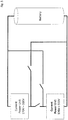
- One solution to overcome this problem, avoiding replacements of presently used converter units, is to connected two or more units together, as represented in figure 3 , each having a predetermined voltage, for instance between 170 V and 500 V, and to increase the voltage to be provided to the accumulators up to the sum of the voltages of each converter unit.
- Another solution to overcome the compatibility problem mentioned above is to introduce a switch between the converter units, to use the units together (switch switched on) or separately (switch switched off), and to connect each converter unit directly to the accumulator to be recharged through a corresponding switch ( figure 5 ).
- the accumulator is detected to have a voltage substantially equal to the voltages provided by both converter units, than the switch between the converter units is closed (on) and the switches between the units and the accumulator are opened (off). In this way, the two units are used together to recharge the accumulator.
- the problem at the base of the present invention is to provide a system to recharge an accumulator of an EV which is compatible with substantially all the accumulators presently available and also with upcoming accumulators, i.e. accumulators characterized by higher voltages, at the same time the system being safe and preventing accidental usage of too high voltages, when an accumulator is not compatible with high voltages or dangerous short circuits, overcoming all the limitations that presently affect the system of the prior art.
- the solution at the base of the present invention is to provide a system to recharge an accumulator of electric energy of an electric vehicle (EV), comprising the features of claim 1.
- EV electric vehicle
- the switch is switched off, one or both the converter units recharge the accumulator through the corresponding circuit, and a current flow from the accumulator to each of the converter units is blocked through the diodes.
- both the converter units are used for recharging the accumulator through the series connection. In this case, if required by circumstances, a current flow from the accumulator to the converter units is allowed through the series connection.
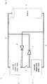
- FIG 7 it is schematically represented and indicated with number 1 a system to recharge an accumulator 2 of electric energy of an electric vehicle (EV) according to the present invention.
- EV electric vehicle
- the system 1 includes a first converter unit 3 connectable to the accumulator 2, to transfer electric energy from the first converter unit 3 to the accumulator 2.
- the converter unit 3 is included in a charging power station, provided with a plug to connect a socket of an electric cable, the cable being also adapted to be connected, at another end, to the accumulator 2 of the electric vehicle, in particular a car.
- the first converter unit 3 has a first voltage V3 and may form a first electrical circuit 8 with the accumulator. For instance, the converter unit 3 provides a voltage between 170 V and 500 V.
- the accumulator 2 is characterized by specific electric parameters, including a voltage V2 and a current C.
- Accumulators of different EVs may be characterized by different electric parameters V2, C.
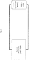
- an accumulator 2 of a first EV may have first electric parameters, for example a voltage between 300 V and 418 V, as schematically represented in figure 9 ; an accumulator 2 of another EV may have second electric parameters, for example a voltage between 700 V and 920 V, as schematically represented in figure 8 .
- the system 1 includes also a second converter unit 4, included in a charging power station which may be provided with a plug to connect a socket of an electric cable, the cable may also be adapted to be connected, at another end, to the accumulator 2 of the electric vehicle.
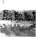
- the same charging power station includes the first and the second converter units, as represented in figure 10 and 11 .
- the second converter unit 4 has a second voltage V4 and may form a second electrical circuit 9 with the accumulator.
- the second converter unit for instance, provides same voltages of the first converter unit, i.e. between 170 V and 500 V and, therefore, it is adapted to recharge accumulator 2 compatible with first electric parameters, through the second electrical circuit 9.
- the first converter unit 3 and the second converter unit 4 are each connectable to the accumulators 2 to transfer electric energy. Energy may be transferred to the accumulator from one of the first and second converting units, or from both the converter units in parallel to the accumulator.
- the system includes means to selectively control recharge of the accumulator 2 with one of the first or the second converter units 3, 4, or with both the first and the second converter units 3, 4 in parallel.
- the accumulator 2 may be recharged with the first and second converter units 3, 4 in parallel and with a voltage still between 170 V and 500 V, but with a higher current than the current provided by only one of the first and second converter units, when used alone.
- the accumulator 2 may be recharged with only one of the first and second converter units, with a voltage still between 170 V and 500 V, but with the current provided by said only one converter unit. In all these cases, the recharge is through the circuits 8 and/or 9.
- the converter unit 3 or 4 has a voltage too low to recharge alone the accumulator or to recharge it with said parallel connection.
- the system 1 of the present invention provides that the first converter unit 3 and the second converter unit 4 are also connectable together in series.
- the system includes a switch 5 adapted to connect in series the first converter unit 3 and the second converter unit 4 and to form a third electrical circuit 10 ( fig. 8 ) connecting in series the first and second converter units with the accumulator 2, to recharge the accumulator 2 with a higher voltage provided by the first converter unit 3 and the second connected unit 4 in series.
- the accumulator may be recharged with a voltage between 340 V and 1000 V if the units connected in series.
- a first diode 6 is between the accumulator 2 and the first converter unit 3, to prevent a current flow from the accumulator 2 to the first converter unit 3 on the first electrical circuit 8.
- a second diode 7 is between the accumulator 2 and the second converter unit 4, to prevent a current flow from the accumulator 2 to the second converter unit 4 on the second electrical circuit 9.
- This diodes 6, 7 prevents short circuits when the switch is switched on to recharge the accumulator through the third circuits 10.
- the circuit 8, 9, or 10 to be used to recharge the accumulator is selected through a controller.
- the controller controls the switch 5.
- the controller detects a voltage V2 of the accumulator 2 and opens the switch (switch off) if a voltage V3+V4 of the first and second converter units 3, 4 connected in series is not compatible with the voltage V2 of the accumulator.
- the controller opens the switch, since the voltage of the first and second converter units 3, 4 connected in series is not compatible (too high) with the voltage of the accumulator.
- the controller closes the switch (switch on) if the voltage V2 of the accumulator is compatible with the voltage V3+V4 of the first and second converter units 3, 4 connected in series; this happens for instance when the first circuit has a voltage between 170 V and 500 V, the second circuit has a voltage between of 170 V and 500 V and the accumulator has a voltage between 700 V and 900 V. In this case, the accumulator is recharged on the third circuit 10.
- a current flow from the accumulator 2 to the first and the second converter units 3, 4 connected in series is allowed when the switch is closed (switched on), as well as a current flow from the first and the second converter units 3, 4 to the accumulator 2. Therefore, advantageously, depending on the application, for instance on the load of the electrical grid or on user requirements, the system may control recharge of the accumulator or recharge of the station(s) associated to the converter units on the circuit 10.
- the invention further relates to a method of controlling the recharge of an accumulator.
- the method may be used to control the system as described above.
- the controller opens the switch 5 and therefore the accumulator 2 is connected to the converter unit 3 through diode 6 and to the converter unit 4 through diode 7, and may receive electric energy through this two converter units in parallel, or through only one connection conversion unit.
- the controller closes the switch 5 and therefore the accumulator 2 is connected to the first and second converter units 3, 4 in series and receives electric energy through both the first and the second converter units. Diodes 6 and 7 prevents short circuits.
- the controller is configured to open the switch 5, if a voltage of the accumulator 2 is compatible with a voltage of only one of the first and second converter units 3, 4 (in the example above, the unit 3), or to close the switch 5, if the voltage of the accumulator 2 is compatible with a sum of the voltages of the first and second converter units 3, 4.
- controller is further configured to make the following compatibility check:
- the accumulator when the voltage of the accumulator 2 is compatible with both the voltage of the first and second converter units connected in parallel and with the voltage of the first and second converter units connected in series, the accumulator is preferably recharged with the units connected in parallel, due to a higher output current than the current provided by a series connection.
- FIG. 12 is a block diagram schematically representing the controller in the system. Power converter units are provided to transfer energy to the accumulator 2 by series or parallel operation of the converter units. A galvanic isolation of the power converter units is provided. The series switch may work only when power converters are galvanic isolated.
- the system of the present invention improves safety and allow to adapt presently used recharging stations (units) to upcoming accumulators having electric parameters not compatible with electric parameters of converter units taken alone, solving all the problems presently affecting the prior art system and avoiding risks for the users.
Landscapes
- Engineering & Computer Science (AREA)
- Power Engineering (AREA)
- Transportation (AREA)
- Mechanical Engineering (AREA)
- Charge And Discharge Circuits For Batteries Or The Like (AREA)
- Electric Propulsion And Braking For Vehicles (AREA)
Claims (6)
- System (1) zum Wiederaufladen eines elektrischen Energiespeichers (2) eines Elektrofahrzeugs (EV), umfassend:- eine erste Wandlereinheit (3) mit einer ersten Spannung (V3) und mindestens eine zweite Wandlereinheit (4) mit einer zweiten Spannung (V4),- eine erste elektrische Schaltung (8), die die erste Wandlereinheit (3) und den Energiespeicher (2) verbindet, um den Energiespeicher (2) mit der ersten Wandlereinheit (3) wiederaufzuladen,- eine zweite elektrische Schaltung (9), die die zweite Wandlereinheit (4) und den Energiespeicher (2) verbindet, um den Energiespeicher (2) mit der zweiten Wandlereinheit (4) wiederaufzuladen,wobei die erste Wandlereinheit (3) und die zweite Wandlereinheit (4) galvanisch isoliert sind;
wobei die erste Wandlereinheit (3) und die zweite Wandlereinheit (4) in einer Aufladestation enthalten sind;
gekennzeichnet durch:- einen Schalter (5), der mit der ersten Wandlereinheit (3) und mit der zweiten Wandlereinheit (4) verbunden ist und dazu ausgebildet ist, die erste Wandlereinheit (3) und die zweite Wandlereinheit (4) in Reihe zu schalten und eine dritte elektrische Schaltung (10) zu bilden, die die erste und die zweite Wandlereinheit in Reihe mit dem Energiespeicher (2) verbindet, um den Energiespeicher (2) mit der ersten Wandlereinheit (3) und der zweiten verbundenen Einheit (4) in Reihe wiederaufzuladen,:- eine erste Diode (6) zwischen dem Energiespeicher (2) und der ersten Wandlereinheit (3) an der ersten elektrischen Schaltung (8), wobei ein Ende der ersten Diode (6) mit der Verbindung des Schalters (5) mit der ersten Wandlereinheit (3) verbunden ist und ein entgegengesetztes Ende mit einem Anschluss des Energiespeichers (2) verbunden ist, um einen Stromfluss vom Energiespeicher (2) zur ersten Wandlereinheit (3) an der ersten elektrischen Schaltung (8) zu verhindern,- eine zweite Diode (7) zwischen dem Energiespeicher (2) und der zweiten Wandlereinheit (4) an der zweiten elektrischen Schaltung (9), wobei ein Ende der zweiten Diode (7) mit der Verbindung des Schalters (5) mit der zweiten Wandlereinheit (4) verbunden ist und ein entgegengesetztes Ende mit dem anderen Anschluss des Energiespeichers (2) verbunden ist, um einen Stromfluss vom Energiespeicher (2) zur zweiten Wandlereinheit (4) an der zweiten elektrischen Schaltung (9) zu verhindern,- eine Steuerung des Schalters (5), die dazu ausgebildet ist, eine Spannung (V2) des Energiespeichers (2) zu erfassen, und dazu ausgebildet ist, den Schalter zu öffnen (Ausschaltung) und den Energiespeicher (2) mit einer der ersten oder der zweiten Wandlereinheit (3, 4) an der ersten und zweiten elektrischen Schaltung (8, 9) oder mit sowohl der ersten als auch der zweiten Wandlereinheit (3, 4) parallel wiederaufzuladen, wenn eine Spannung (V3+V4) der ersten und zweiten Wandlereinheit (3, 4), die in Reihe geschaltet sind, nicht mit der Spannung (V2) des Energiespeichers kompatibel ist, oder den Schalter zu schließen (Einschaltung) und den Energiespeicher (2) mit der ersten und der zweiten Wandlereinheit (3, 4) in Reihe an der dritten elektrischen Schaltung (10) wiederaufzuladen oder um Strom von dem Energiespeicher (2) zu der ersten und der zweiten Wandlereinheit (3, 4) bereitzustellen, wenn die Spannung (V2) des Energiespeichers mit der die Spannung (V3+V4) der ersten und zweiten Wandlereinheit (3, 4), die in Reihe geschaltet sind, kompatibel ist - System nach Anspruch 1, dadurch gekennzeichnet, dass die Steuerung dazu konfiguriert ist, den Schalter (5) zu öffnen, um den Energiespeicher (2) mit der ersten und der zweiten Wandlereinheit (3, 4) parallel wiederaufzuladen, wenn die Spannung (V2) des Energiespeichers sowohl mit der Spannung (V3+V4) der ersten und zweiten Wandlereinheit (3, 4), die in Reihe geschaltet sind, als auch mit der Spannung (V3, V4) der ersten und zweiten Wandlereinheit (3, 4), die parallel geschaltet sind, kompatibel ist.
- System nach Anspruch 1, dadurch gekennzeichnet, dass die Steuerung dazu konfiguriert ist, den Schalter (5) zu öffnen, wenn die Spannung (V2) des Energiespeichers (2) mit der Spannung (V3, V4) von nur einer der ersten und zweiten Wandlereinheit (3, 4) kompatibel ist, oder den Schalter (5) zu schließen, wenn die Spannung des Energiespeichers (2) mit einer Summe der Spannungen (V3, V4) der ersten und zweiten Wandlereinheit (3, 4) kompatibel ist, wobei die Steuerung weiter konfiguriert ist, um die folgende Kompatibilitätsprüfung durchzuführen:- Vergleichen der Spannung (V2) des Energiespeichers (2) mit der Spannung (V3) der ersten Wandlereinheit (3) und/oder Vergleichen der Spannung (V2) des Energiespeichers (2) mit der Spannung (V4) der zweiten Wandlereinheit (4);- Schließen des Schalters, wenn die Spannung (V2) des Energiespeichers größer ist als die Spannung (V3, V4) von mindestens einer der ersten und zweiten Wandlereinheit von einem vorbestimmten Schwellenwert.
- System nach Anspruch 1, wobei die erste Wandlereinheit (3) eine Spannung (V3) zwischen 170 V und 500 V aufweist und die zweite Wandlereinheit eine Spannung (V4) zwischen 170 V und 500 V aufweist und der Energiespeicher eine Spannung (V2) zwischen 700 V und 900 V aufweist.
- Verfahren (1) zum Wiederaufladen eines elektrischen Energiespeichers (2) eines Elektrofahrzeugs (EV), umfassend:- Verbinden einer ersten galvanisch isolierten Wandlereinheit (3) und des Energiespeichers (2) in einer ersten elektrischen Schaltung (8), um den Energiespeicher (2) mit der ersten Wandlereinheit (3) wiederaufzuladen,- Verbinden einer zweiten galvanisch isolierten Wandlereinheit (4) und des Energiespeichers (2) in einer zweiten elektrischen Schaltung (9), um den Energiespeicher (2) mit der zweiten Wandlereinheit (4) wiederaufzuladen,- selektives Steuern der Wiederaufladung des Energiespeichers (2) mit einer der ersten oder der zweiten Wandlereinheit (3, 4) an der ersten und zweiten elektrischen Schaltung (8, 9) oder mit sowohl der ersten als auch der zweiten Wandlereinheit (3, 4) parallel,- Bereitstellen eines Schalters (5), der mit der ersten Wandlereinheit (3) und mit der zweiten Wandlereinheit (4) verbunden ist und dazu ausgebildet ist, die erste Wandlereinheit (3) und die zweite Wandlereinheit (4) in Reihe zu schalten und eine dritte elektrische Schaltung (10) zu bilden, die die erste und die zweite Wandlereinheit in Reihe mit dem Energiespeicher (2) verbindet, um den Energiespeicher (2) mit der ersten Wandlereinheit (3) und der zweiten verbundenen Einheit (4) in Reihe wiederaufzuladen,gekennzeichnet durch:- ferner Bereitstellen einer ersten Diode (6) zwischen dem Energiespeicher (2) und der ersten Wandlereinheit (3) an der ersten elektrischen Schaltung (8), wobei ein Ende der ersten Diode (6) mit der Verbindung des Schalters (5) mit der ersten Wandlereinheit (3) verbunden ist und ein entgegengesetztes Ende mit einem Anschluss des Energiespeichers (2) verbunden ist, um einen Stromfluss vom Energiespeicher (2) zur ersten Wandlereinheit (3) an der ersten elektrischen Schaltung (8) zu verhindern, und- eine zweite Diode (7) zwischen dem Energiespeicher (2) und der zweiten Wandlereinheit (4) an der zweiten elektrischen Schaltung (9), wobei ein Ende der zweiten Diode (7) mit der Verbindung des Schalters (5) mit der zweiten Wandlereinheit (4) verbunden ist und ein entgegengesetztes Ende mit dem anderen Anschluss des Energiespeichers (2) verbunden ist, um einen Stromfluss vom Energiespeicher (2) zur zweiten Wandlereinheit (4) an der zweiten elektrischen Schaltung (9) zu verhindern,- Erfassen einer Spannung (V2) des Energiespeichers (2);- Öffnen des Schalters (Ausschalten), wenn eine Spannung (V3+V4) der ersten und zweiten Wandlereinheit (3, 4), die in Reihe geschaltet sind, nicht mit der Spannung (V2) des Energiespeichers kompatibel ist, und Wiederaufladen des Energiespeichers (2) mit einer der ersten oder der zweiten Wandlereinheit (3, 4) an der ersten und zweiten elektrischen Schaltung (8, 9) oder mit sowohl der ersten als auch der zweiten Wandlereinheit (3, 4) parallel, oder- Schließen des Schalters (Einschalten), wenn die Spannung (V2) des Energiespeichers mit der Spannung (V3+V4) der ersten und zweiten Wandlereinheit (3, 4), die in Reihe geschaltet sind, kompatibel ist, und Wiederaufladen des Energiespeichers (2) mit der ersten und der zweiten Wandlereinheit (3, 4) in Reihe an der dritten elektrischen Schaltung (10) oder um Strom von dem Energiespeicher (2) zu der ersten und der zweiten Wandlereinheit (3, 4) bereitzustellen
- Verfahren nach Anspruch 5, dadurch gekennzeichnet, dass die Steuerung den Schalter (5) öffnet, um den Energiespeicher (2) mit der ersten und der zweiten Wandlereinheit (3, 4) parallel wiederaufzuladen, wenn die Spannung (V2) des Energiespeichers sowohl mit der Spannung (V3+V4) der ersten und zweiten Wandlereinheit (3, 4), die in Reihe geschaltet sind, als auch mit der Spannung (V3, V4) der ersten und zweiten Wandlereinheit (3, 4), die parallel geschaltet sind, kompatibel ist.
Applications Claiming Priority (1)
| Application Number | Priority Date | Filing Date | Title |
|---|---|---|---|
| CH01610/16A CH713182B1 (it) | 2016-12-07 | 2016-12-07 | Sistema per ricaricare un accumulatore di energia di un veicolo elettrico. |
Publications (2)
| Publication Number | Publication Date |
|---|---|
| EP3333009A1 EP3333009A1 (de) | 2018-06-13 |
| EP3333009B1 true EP3333009B1 (de) | 2019-03-20 |
Family
ID=60201355
Family Applications (1)
| Application Number | Title | Priority Date | Filing Date |
|---|---|---|---|
| EP17198756.3A Active EP3333009B1 (de) | 2016-12-07 | 2017-10-27 | System zum wiederaufladen eines energiespeichers eines elektrofahrzeugs |
Country Status (2)
| Country | Link |
|---|---|
| EP (1) | EP3333009B1 (de) |
| CH (1) | CH713182B1 (de) |
Families Citing this family (4)
| Publication number | Priority date | Publication date | Assignee | Title |
|---|---|---|---|---|
| CN110768314B (zh) * | 2018-07-26 | 2022-01-07 | 比亚迪股份有限公司 | 轨道车辆及其充电系统、充电控制装置和方法 |
| DE102018133512A1 (de) * | 2018-12-21 | 2020-06-25 | Jungheinrich Aktiengesellschaft | Ladeanordnung für Flurförderzeuge |
| AT522293B1 (de) * | 2019-04-09 | 2023-09-15 | Avl List Gmbh | Prüfvorrichtung für ein elektrisches Prüfen eines Prüflings |
| EP4290753A4 (de) * | 2021-02-05 | 2024-03-20 | Huawei Digital Power Technologies Co., Ltd. | Ladeschaltung und ladevorrichtung |
Family Cites Families (4)
| Publication number | Priority date | Publication date | Assignee | Title |
|---|---|---|---|---|
| US6140799A (en) * | 1999-06-29 | 2000-10-31 | Thomasson; Mark J. | Switched battery-bank assembly for providing incremental voltage control |
| US6664762B2 (en) * | 2001-08-21 | 2003-12-16 | Power Designers, Llc | High voltage battery charger |
| US7489048B2 (en) * | 2006-01-09 | 2009-02-10 | General Electric Company | Energy storage system for electric or hybrid vehicle |
| WO2014207267A1 (es) * | 2013-06-28 | 2014-12-31 | Fundación Circe - Centro De Investigacion De Recursos Y Consumos Energeticos | Sistema modular de carga inductiva para vehículos eléctricos |
-
2016
- 2016-12-07 CH CH01610/16A patent/CH713182B1/it unknown
-
2017
- 2017-10-27 EP EP17198756.3A patent/EP3333009B1/de active Active
Non-Patent Citations (1)
| Title |
|---|
| None * |
Also Published As
| Publication number | Publication date |
|---|---|
| EP3333009A1 (de) | 2018-06-13 |
| CH713182A2 (it) | 2018-06-15 |
| CH713182B1 (it) | 2018-10-15 |
Similar Documents
| Publication | Publication Date | Title |
|---|---|---|
| US10106043B2 (en) | Charging device for an electric vehicle | |
| US10587205B2 (en) | Switching power supply device including an inrush current prevention circuit | |
| US11607967B2 (en) | Vehicle electrical system having a power inverter and an electric motor for stepping up voltage | |
| US11161424B2 (en) | On-board vehicle electrical system for charging an electrically operated vehicle, and method | |
| KR102485328B1 (ko) | 전기 자동차의 충전 제어 장치 | |
| EP3333009B1 (de) | System zum wiederaufladen eines energiespeichers eines elektrofahrzeugs | |
| US11569745B2 (en) | Electrical system having boost converter functionality | |
| CN104953696B (zh) | 在线互动式不间断电源 | |
| EP2774800A1 (de) | Stromempfänger und Ladesystem | |
| US20150274024A1 (en) | Charge transfer method and related electric device | |
| US12206273B2 (en) | Universal and versatile charger for electric vehicle battery | |
| JP2023517116A (ja) | 電気自動車充電コントローラおよびこれを含む電気自動車充電装置 | |
| US20210028642A1 (en) | Electrical energy storage system and method for operating same | |
| US20200016991A1 (en) | Conversion device, associated control method and associated vehicle | |
| JP2013243898A (ja) | 充電装置 | |
| US10530173B2 (en) | Charging device and control method therefor | |
| US11130413B2 (en) | Arrangement of multiple electrical machines for a vehicle for improving the energy supply while reducing installation space and weight | |
| KR20220072873A (ko) | 차량 전기 시스템 | |
| US10661662B2 (en) | Battery charger for electric vehicles | |
| US11283366B2 (en) | Rectifier arrangement | |
| JP2023512545A (ja) | 電気自動車充電コントローラ | |
| EP4545349A1 (de) | Leistungswandler | |
| JP2012029424A (ja) | 充電器および電動移動体用バッテリの充電方法 | |
| US12322993B2 (en) | Battery charger with a plurality of secondary transformer circuits | |
| CN116507524A (zh) | 具有直流终端和交流终端的充电电路,以及具有充电电路的车辆电气系统 |
Legal Events
| Date | Code | Title | Description |
|---|---|---|---|
| PUAI | Public reference made under article 153(3) epc to a published international application that has entered the european phase |
Free format text: ORIGINAL CODE: 0009012 |
|
| STAA | Information on the status of an ep patent application or granted ep patent |
Free format text: STATUS: THE APPLICATION HAS BEEN PUBLISHED |
|
| AK | Designated contracting states |
Kind code of ref document: A1 Designated state(s): AL AT BE BG CH CY CZ DE DK EE ES FI FR GB GR HR HU IE IS IT LI LT LU LV MC MK MT NL NO PL PT RO RS SE SI SK SM TR |
|
| AX | Request for extension of the european patent |
Extension state: BA ME |
|
| STAA | Information on the status of an ep patent application or granted ep patent |
Free format text: STATUS: REQUEST FOR EXAMINATION WAS MADE |
|
| 17P | Request for examination filed |
Effective date: 20180712 |
|
| RBV | Designated contracting states (corrected) |
Designated state(s): AL AT BE BG CH CY CZ DE DK EE ES FI FR GB GR HR HU IE IS IT LI LT LU LV MC MK MT NL NO PL PT RO RS SE SI SK SM TR |
|
| GRAP | Despatch of communication of intention to grant a patent |
Free format text: ORIGINAL CODE: EPIDOSNIGR1 |
|
| RIC1 | Information provided on ipc code assigned before grant |
Ipc: H02M 1/00 20060101ALN20180831BHEP Ipc: B60L 11/18 20060101AFI20180831BHEP Ipc: H02J 7/00 20060101ALI20180831BHEP |
|
| STAA | Information on the status of an ep patent application or granted ep patent |
Free format text: STATUS: GRANT OF PATENT IS INTENDED |
|
| RIC1 | Information provided on ipc code assigned before grant |
Ipc: H02J 7/00 20060101ALI20180919BHEP Ipc: H02M 1/00 20060101ALN20180919BHEP Ipc: B60L 11/18 20060101AFI20180919BHEP |
|
| INTG | Intention to grant announced |
Effective date: 20181011 |
|
| GRAS | Grant fee paid |
Free format text: ORIGINAL CODE: EPIDOSNIGR3 |
|
| GRAA | (expected) grant |
Free format text: ORIGINAL CODE: 0009210 |
|
| STAA | Information on the status of an ep patent application or granted ep patent |
Free format text: STATUS: THE PATENT HAS BEEN GRANTED |
|
| AK | Designated contracting states |
Kind code of ref document: B1 Designated state(s): AL AT BE BG CH CY CZ DE DK EE ES FI FR GB GR HR HU IE IS IT LI LT LU LV MC MK MT NL NO PL PT RO RS SE SI SK SM TR |
|
| REG | Reference to a national code |
Ref country code: GB Ref legal event code: FG4D |
|
| REG | Reference to a national code |
Ref country code: CH Ref legal event code: EP |
|
| REG | Reference to a national code |
Ref country code: DE Ref legal event code: R096 Ref document number: 602017002827 Country of ref document: DE |
|
| REG | Reference to a national code |
Ref country code: AT Ref legal event code: REF Ref document number: 1110182 Country of ref document: AT Kind code of ref document: T Effective date: 20190415 |
|
| REG | Reference to a national code |
Ref country code: IE Ref legal event code: FG4D |
|
| REG | Reference to a national code |
Ref country code: NO Ref legal event code: T2 Effective date: 20190320 |
|
| REG | Reference to a national code |
Ref country code: NL Ref legal event code: FP |
|
| PG25 | Lapsed in a contracting state [announced via postgrant information from national office to epo] |
Ref country code: SE Free format text: LAPSE BECAUSE OF FAILURE TO SUBMIT A TRANSLATION OF THE DESCRIPTION OR TO PAY THE FEE WITHIN THE PRESCRIBED TIME-LIMIT Effective date: 20190320 Ref country code: LT Free format text: LAPSE BECAUSE OF FAILURE TO SUBMIT A TRANSLATION OF THE DESCRIPTION OR TO PAY THE FEE WITHIN THE PRESCRIBED TIME-LIMIT Effective date: 20190320 Ref country code: FI Free format text: LAPSE BECAUSE OF FAILURE TO SUBMIT A TRANSLATION OF THE DESCRIPTION OR TO PAY THE FEE WITHIN THE PRESCRIBED TIME-LIMIT Effective date: 20190320 |
|
| REG | Reference to a national code |
Ref country code: LT Ref legal event code: MG4D |
|
| PG25 | Lapsed in a contracting state [announced via postgrant information from national office to epo] |
Ref country code: LV Free format text: LAPSE BECAUSE OF FAILURE TO SUBMIT A TRANSLATION OF THE DESCRIPTION OR TO PAY THE FEE WITHIN THE PRESCRIBED TIME-LIMIT Effective date: 20190320 Ref country code: RS Free format text: LAPSE BECAUSE OF FAILURE TO SUBMIT A TRANSLATION OF THE DESCRIPTION OR TO PAY THE FEE WITHIN THE PRESCRIBED TIME-LIMIT Effective date: 20190320 Ref country code: BG Free format text: LAPSE BECAUSE OF FAILURE TO SUBMIT A TRANSLATION OF THE DESCRIPTION OR TO PAY THE FEE WITHIN THE PRESCRIBED TIME-LIMIT Effective date: 20190620 Ref country code: GR Free format text: LAPSE BECAUSE OF FAILURE TO SUBMIT A TRANSLATION OF THE DESCRIPTION OR TO PAY THE FEE WITHIN THE PRESCRIBED TIME-LIMIT Effective date: 20190621 Ref country code: HR Free format text: LAPSE BECAUSE OF FAILURE TO SUBMIT A TRANSLATION OF THE DESCRIPTION OR TO PAY THE FEE WITHIN THE PRESCRIBED TIME-LIMIT Effective date: 20190320 |
|
| PG25 | Lapsed in a contracting state [announced via postgrant information from national office to epo] |
Ref country code: ES Free format text: LAPSE BECAUSE OF FAILURE TO SUBMIT A TRANSLATION OF THE DESCRIPTION OR TO PAY THE FEE WITHIN THE PRESCRIBED TIME-LIMIT Effective date: 20190320 Ref country code: AL Free format text: LAPSE BECAUSE OF FAILURE TO SUBMIT A TRANSLATION OF THE DESCRIPTION OR TO PAY THE FEE WITHIN THE PRESCRIBED TIME-LIMIT Effective date: 20190320 Ref country code: PT Free format text: LAPSE BECAUSE OF FAILURE TO SUBMIT A TRANSLATION OF THE DESCRIPTION OR TO PAY THE FEE WITHIN THE PRESCRIBED TIME-LIMIT Effective date: 20190720 Ref country code: SK Free format text: LAPSE BECAUSE OF FAILURE TO SUBMIT A TRANSLATION OF THE DESCRIPTION OR TO PAY THE FEE WITHIN THE PRESCRIBED TIME-LIMIT Effective date: 20190320 Ref country code: RO Free format text: LAPSE BECAUSE OF FAILURE TO SUBMIT A TRANSLATION OF THE DESCRIPTION OR TO PAY THE FEE WITHIN THE PRESCRIBED TIME-LIMIT Effective date: 20190320 Ref country code: CZ Free format text: LAPSE BECAUSE OF FAILURE TO SUBMIT A TRANSLATION OF THE DESCRIPTION OR TO PAY THE FEE WITHIN THE PRESCRIBED TIME-LIMIT Effective date: 20190320 Ref country code: EE Free format text: LAPSE BECAUSE OF FAILURE TO SUBMIT A TRANSLATION OF THE DESCRIPTION OR TO PAY THE FEE WITHIN THE PRESCRIBED TIME-LIMIT Effective date: 20190320 |
|
| PG25 | Lapsed in a contracting state [announced via postgrant information from national office to epo] |
Ref country code: SM Free format text: LAPSE BECAUSE OF FAILURE TO SUBMIT A TRANSLATION OF THE DESCRIPTION OR TO PAY THE FEE WITHIN THE PRESCRIBED TIME-LIMIT Effective date: 20190320 Ref country code: PL Free format text: LAPSE BECAUSE OF FAILURE TO SUBMIT A TRANSLATION OF THE DESCRIPTION OR TO PAY THE FEE WITHIN THE PRESCRIBED TIME-LIMIT Effective date: 20190320 |
|
| PG25 | Lapsed in a contracting state [announced via postgrant information from national office to epo] |
Ref country code: IS Free format text: LAPSE BECAUSE OF FAILURE TO SUBMIT A TRANSLATION OF THE DESCRIPTION OR TO PAY THE FEE WITHIN THE PRESCRIBED TIME-LIMIT Effective date: 20190720 |
|
| REG | Reference to a national code |
Ref country code: DE Ref legal event code: R097 Ref document number: 602017002827 Country of ref document: DE |
|
| PLBE | No opposition filed within time limit |
Free format text: ORIGINAL CODE: 0009261 |
|
| STAA | Information on the status of an ep patent application or granted ep patent |
Free format text: STATUS: NO OPPOSITION FILED WITHIN TIME LIMIT |
|
| PG25 | Lapsed in a contracting state [announced via postgrant information from national office to epo] |
Ref country code: DK Free format text: LAPSE BECAUSE OF FAILURE TO SUBMIT A TRANSLATION OF THE DESCRIPTION OR TO PAY THE FEE WITHIN THE PRESCRIBED TIME-LIMIT Effective date: 20190320 |
|
| 26N | No opposition filed |
Effective date: 20200102 |
|
| PG25 | Lapsed in a contracting state [announced via postgrant information from national office to epo] |
Ref country code: TR Free format text: LAPSE BECAUSE OF FAILURE TO SUBMIT A TRANSLATION OF THE DESCRIPTION OR TO PAY THE FEE WITHIN THE PRESCRIBED TIME-LIMIT Effective date: 20190320 |
|
| PG25 | Lapsed in a contracting state [announced via postgrant information from national office to epo] |
Ref country code: MC Free format text: LAPSE BECAUSE OF FAILURE TO SUBMIT A TRANSLATION OF THE DESCRIPTION OR TO PAY THE FEE WITHIN THE PRESCRIBED TIME-LIMIT Effective date: 20190320 |
|
| PG25 | Lapsed in a contracting state [announced via postgrant information from national office to epo] |
Ref country code: LU Free format text: LAPSE BECAUSE OF NON-PAYMENT OF DUE FEES Effective date: 20191027 |
|
| REG | Reference to a national code |
Ref country code: BE Ref legal event code: MM Effective date: 20191031 |
|
| PG25 | Lapsed in a contracting state [announced via postgrant information from national office to epo] |
Ref country code: BE Free format text: LAPSE BECAUSE OF NON-PAYMENT OF DUE FEES Effective date: 20191031 |
|
| PG25 | Lapsed in a contracting state [announced via postgrant information from national office to epo] |
Ref country code: IE Free format text: LAPSE BECAUSE OF NON-PAYMENT OF DUE FEES Effective date: 20191027 |
|
| PGFP | Annual fee paid to national office [announced via postgrant information from national office to epo] |
Ref country code: CH Payment date: 20201023 Year of fee payment: 4 |
|
| PG25 | Lapsed in a contracting state [announced via postgrant information from national office to epo] |
Ref country code: CY Free format text: LAPSE BECAUSE OF FAILURE TO SUBMIT A TRANSLATION OF THE DESCRIPTION OR TO PAY THE FEE WITHIN THE PRESCRIBED TIME-LIMIT Effective date: 20190320 |
|
| PG25 | Lapsed in a contracting state [announced via postgrant information from national office to epo] |
Ref country code: MT Free format text: LAPSE BECAUSE OF FAILURE TO SUBMIT A TRANSLATION OF THE DESCRIPTION OR TO PAY THE FEE WITHIN THE PRESCRIBED TIME-LIMIT Effective date: 20190320 Ref country code: HU Free format text: LAPSE BECAUSE OF FAILURE TO SUBMIT A TRANSLATION OF THE DESCRIPTION OR TO PAY THE FEE WITHIN THE PRESCRIBED TIME-LIMIT; INVALID AB INITIO Effective date: 20171027 |
|
| PG25 | Lapsed in a contracting state [announced via postgrant information from national office to epo] |
Ref country code: SI Free format text: LAPSE BECAUSE OF FAILURE TO SUBMIT A TRANSLATION OF THE DESCRIPTION OR TO PAY THE FEE WITHIN THE PRESCRIBED TIME-LIMIT Effective date: 20190320 |
|
| REG | Reference to a national code |
Ref country code: CH Ref legal event code: PL |
|
| PG25 | Lapsed in a contracting state [announced via postgrant information from national office to epo] |
Ref country code: MK Free format text: LAPSE BECAUSE OF FAILURE TO SUBMIT A TRANSLATION OF THE DESCRIPTION OR TO PAY THE FEE WITHIN THE PRESCRIBED TIME-LIMIT Effective date: 20190320 |
|
| REG | Reference to a national code |
Ref country code: AT Ref legal event code: UEP Ref document number: 1110182 Country of ref document: AT Kind code of ref document: T Effective date: 20190320 |
|
| PG25 | Lapsed in a contracting state [announced via postgrant information from national office to epo] |
Ref country code: LI Free format text: LAPSE BECAUSE OF NON-PAYMENT OF DUE FEES Effective date: 20211031 Ref country code: CH Free format text: LAPSE BECAUSE OF NON-PAYMENT OF DUE FEES Effective date: 20211031 |
|
| PGFP | Annual fee paid to national office [announced via postgrant information from national office to epo] |
Ref country code: NO Payment date: 20250925 Year of fee payment: 9 |
|
| PGFP | Annual fee paid to national office [announced via postgrant information from national office to epo] |
Ref country code: IT Payment date: 20250923 Year of fee payment: 9 Ref country code: NL Payment date: 20250923 Year of fee payment: 9 |
|
| PGFP | Annual fee paid to national office [announced via postgrant information from national office to epo] |
Ref country code: GB Payment date: 20250923 Year of fee payment: 9 |
|
| PGFP | Annual fee paid to national office [announced via postgrant information from national office to epo] |
Ref country code: FR Payment date: 20250924 Year of fee payment: 9 |
|
| PGFP | Annual fee paid to national office [announced via postgrant information from national office to epo] |
Ref country code: DE Payment date: 20250923 Year of fee payment: 9 |
|
| PGFP | Annual fee paid to national office [announced via postgrant information from national office to epo] |
Ref country code: AT Payment date: 20250926 Year of fee payment: 9 |