EP3332985A1 - Roue d'aeronef a talon amovible - Google Patents
Roue d'aeronef a talon amovible Download PDFInfo
- Publication number
- EP3332985A1 EP3332985A1 EP17203995.0A EP17203995A EP3332985A1 EP 3332985 A1 EP3332985 A1 EP 3332985A1 EP 17203995 A EP17203995 A EP 17203995A EP 3332985 A1 EP3332985 A1 EP 3332985A1
- Authority
- EP
- European Patent Office
- Prior art keywords
- rim
- key
- removable
- foot
- heel
- Prior art date
- Legal status (The legal status is an assumption and is not a legal conclusion. Google has not performed a legal analysis and makes no representation as to the accuracy of the status listed.)
- Granted
Links
Images


Classifications
-
- B—PERFORMING OPERATIONS; TRANSPORTING
- B60—VEHICLES IN GENERAL
- B60B—VEHICLE WHEELS; CASTORS; AXLES FOR WHEELS OR CASTORS; INCREASING WHEEL ADHESION
- B60B3/00—Disc wheels, i.e. wheels with load-supporting disc body
- B60B3/02—Disc wheels, i.e. wheels with load-supporting disc body with a single disc body integral with rim
-
- B—PERFORMING OPERATIONS; TRANSPORTING
- B60—VEHICLES IN GENERAL
- B60B—VEHICLE WHEELS; CASTORS; AXLES FOR WHEELS OR CASTORS; INCREASING WHEEL ADHESION
- B60B21/00—Rims
- B60B21/12—Appurtenances, e.g. lining bands
-
- B—PERFORMING OPERATIONS; TRANSPORTING
- B60—VEHICLES IN GENERAL
- B60B—VEHICLE WHEELS; CASTORS; AXLES FOR WHEELS OR CASTORS; INCREASING WHEEL ADHESION
- B60B25/00—Rims built-up of several main parts ; Locking means for the rim parts
- B60B25/04—Rims with dismountable flange rings, seat rings, or lock rings
- B60B25/08—Continuous flange rings; Arrangement of recesses enabling the flange rings to be slipped over the rim body
-
- B—PERFORMING OPERATIONS; TRANSPORTING
- B60—VEHICLES IN GENERAL
- B60B—VEHICLE WHEELS; CASTORS; AXLES FOR WHEELS OR CASTORS; INCREASING WHEEL ADHESION
- B60B25/00—Rims built-up of several main parts ; Locking means for the rim parts
- B60B25/04—Rims with dismountable flange rings, seat rings, or lock rings
- B60B25/14—Locking means for flange rings or seat rings
- B60B25/20—Arrangement of screws, bolts, or shouldered pins
-
- B—PERFORMING OPERATIONS; TRANSPORTING
- B64—AIRCRAFT; AVIATION; COSMONAUTICS
- B64C—AEROPLANES; HELICOPTERS
- B64C25/00—Alighting gear
- B64C25/32—Alighting gear characterised by elements which contact the ground or similar surface
- B64C25/34—Alighting gear characterised by elements which contact the ground or similar surface wheeled type, e.g. multi-wheeled bogies
- B64C25/36—Arrangements or adaptations of wheels, tyres or axles in general
-
- B—PERFORMING OPERATIONS; TRANSPORTING
- B60—VEHICLES IN GENERAL
- B60B—VEHICLE WHEELS; CASTORS; AXLES FOR WHEELS OR CASTORS; INCREASING WHEEL ADHESION
- B60B2360/00—Materials; Physical forms thereof
- B60B2360/10—Metallic materials
- B60B2360/104—Aluminum
-
- B—PERFORMING OPERATIONS; TRANSPORTING
- B60—VEHICLES IN GENERAL
- B60Y—INDEXING SCHEME RELATING TO ASPECTS CROSS-CUTTING VEHICLE TECHNOLOGY
- B60Y2200/00—Type of vehicle
- B60Y2200/50—Aeroplanes, Helicopters
- B60Y2200/51—Aeroplanes
Definitions
- the invention relates to an aircraft wheel with removable heel.
- Aircraft wheel rims having a hub connected by a sail to an annular outer portion intended to receive a tire.
- This annular outer portion has at both ends heels, one of which is removable to allow mounting of the tire on the wheel.
- the removable heel is then replaced on the rim with the interposition of a locking ring preventing the removable heel to separate from the rim. It appeared a need to block the removable heel rotation, to avoid any hooping between the removable heel and the rim.
- FR3015951 such a rim whose removable heel is stopped in rotation by means of two links mounted symmetrically relative to each other at an oblique angle between the removable heel and the rim.
- the attachment of these rods on the rim requires to create a tapped hole in the rim to receive a fastening screw of the rod.
- the invention aims to provide an aircraft wheel with detachable heel provided with locking means in rotation of the removable heel does not require to develop a specific interface on the rim to fix said locking means in rotation.
- an aluminum alloy aircraft wheel rim is proposed in two parts, including a main part and a removable part, the main part comprising a hub, a sail extending between the hub and an annular outer portion for receiving a tire and shaped to have a heel at one of its ends, the other of its ends being shaped to receive the removable removable heel portion which is attached to the annular outer portion after placement of the tire, the rim comprising means for locking in rotation of the removable heel relative to the rim.
- the locking means comprise at least one key having a head engaged in a corresponding receptacle of the removable heel and a foot fixed to the main part of the rim by means of at least one steel stud hooped in the part main and extending parallel to an axis of rotation of the wheel to project from the rim and receive the foot of the key.
- the pin is wrapped in a hole of the rim which also serves to receive an end of a drive bar in rotation of brake rotor discs.
- the invention applies to an aircraft rim 1 having a hub 2 for receiving bearings for guiding the rotation of the rim on an aircraft landing gear axle about an axis of rotation.
- the hub 2 is connected by a web 3 whose hollows and branches are visible to an annular outer portion 4 intended to receive a tire (not shown here).
- the annular outer portion 4 is terminated at one of its ends by a heel 5 integrally. The whole forms the main part of the rim. It is completed by a removable portion, in this case a removable heel 6 which is attached to the other end of the annular outer portion and can be removed to allow mounting of a tire.
- the removable heel 6 is attached to the rim with the interposition of a rod 7 axially blocking the bead and preventing its extraction under the effect of the pressure of the tire.
- a seal 8 is interposed between the rim 1 and the removable heel 6 to allow inflation of the tire.
- the main part, which will be called here rim to simplify the description, and the removable heel are here made of aluminum alloy.
- the removable heel 6 is stopped in rotation on the rim 1 by means of a key 10 having on the one hand a head 11 engaged in a receptacle of the detachable heel 6 delimited laterally by stops 9, and secondly a foot 12 ending here by two ears 13 pierced.
- the lugs 13 are threaded on steel pins 14 which are engaged in openings 15 of the rim 1 opening which extend parallel to the axis of rotation of the rim.
- the pins 14 have a flared internal end 16 which bears against a shoulder 18 of the orifice 15 for its axial stop.
- the pins 14 are hooped in the end of the orifices 16 to protrude from the rim 1 and receive the ears of the foot of the key 10.
- the key 10 opposes any rotation of the removable heel 6 on the rim 1.
- the keys 10 are immobilized by means of screws 17 screwed into a tapping of the pin 14 and holding a lock washer 19 which axially immobilizes the lug.
- lug 13 of the key 10 threaded onto the pin 14 leaving a slight axial clearance to allow the key 10 a slight axial movement to accommodate mounting games or deformations of the removable heel 6.
- the orifices 16 also serve to receive the terminal finger of a bar 20 serving to drive in rotation with the rim of the brake rotor discs (not shown) which extend inside the rim .
- the orifice 16 it suffices just to extend the orifice 16 to make it open on the lateral face of the rim, to enable it to receive a hooped pawn 14. No additional tapped hole is to be provided on the rim to fix the foot of the rim. the key 10 on the rim.
- the key 110 now comprises a pierced right foot 112 which is threaded directly onto one of the hooped pins 114 protruding from the rim 101.
- the end of the pin 114 has been threaded to receive a nut 121 for axial stop of the key 110.
- a bonze insert 122 which extends between the head 111 of the key 110 and the stops 109 to protect it against matting.
- the key 110 comprises a head 111 provided with a cap 123 which cap the top of the stops 109 to obtain a self-tightening effect between the key attached to the pin 114 and the removable heel 106 in case it had tendency to rotate relative to the rim.
- the keys 210 which each comprise heads 211 cooperating with the removable heel 206, are here grouped in pairs, each of the pairs sharing a common foot 212 which is reported on two pieces 214.
- the pins 14, 114, 214 are preferably positioned and shrunk into the orifices which moreover receive the rotational drive lugs of the rotor discs of the brakes, it is of course possible, especially if the rim is not intended to equip a braked wheel, to provide specific orifices machined in the rim to receive the pins.
Landscapes
- Engineering & Computer Science (AREA)
- Mechanical Engineering (AREA)
- Aviation & Aerospace Engineering (AREA)
- Tires In General (AREA)
- Braking Arrangements (AREA)
Abstract
Description
- L'invention concerne une roue d'aéronef à talon amovible.
- On connaît des jantes de roue d'aéronef comportant un moyeu relié par un voile à une portion externe annulaire destinée à recevoir un pneumatique. Cette portion externe annulaire comporte à ses deux extrémités des talons, dont l'un est amovible pour permettre le montage du pneumatique sur la roue. Le talon amovible est alors remis en place sur la jante avec interposition d'un jonc de blocage empêchant le talon amovible de se séparer de la jante. Il est apparu un besoin pour bloquer le talon amovible en rotation, afin d'éviter tout frettage entre le talon amovible et la jante.
- On connaît du document
FR3015951 - L'invention vise à proposer une roue d'aéronef à talon amovible munie de moyens de blocage en rotation du talon amovible ne nécessitant pas de développer une interface spécifique sur la jante pour fixer lesdits moyens de blocage en rotation.
- En vue de la réalisation de ce but, on propose une jante de roue d'aéronef en alliage d'aluminium réalisée en deux parties dont une partie principale et une partie amovible, la partie principale comportant un moyeu, un voile s'étendant entre le moyeu et une portion externe annulaire destinée à recevoir un pneumatique et conformée pour présenter un talon à l'une de ses extrémités, l'autre de ses extrémités étant conformée pour recevoir la partie amovible formant talon amovible qui est rapportée sur la portion externe annulaire après mise en place du pneumatique, la jante comportant des moyens de blocage en rotation du talon amovible relativement à la jante. Selon l'invention, les moyens de blocage comportent au moins une clavette ayant une tête engagée dans un réceptacle conforme du talon amovible et un pied fixé à la partie principale de la jante au moyen d'au moins un pion en acier fretté dans la partie principale et s'étendant parallèlement à un axe de rotation de la roue pour saillir de la jante et recevoir le pied de la clavette.
- De préférence, le pion est fretté dans un orifice de la jante qui sert par ailleurs à recevoir une extrémité d'une barrette d'entraînement en rotation de disques rotors de frein.
- L'invention sera mieux comprise à la lumière de la description détaillée qui suit de modes particuliers de réalisation de l'invention, en référence aux figures des dessins annexés parmi lesquelles :
- La
figure 1 est une vue en perspective d'une partie d'une jante d'aéronef selon un premier mode particulier de réalisation de l'invention; - La
figure 2 est une vue en coupe de lafigure 1 au niveau de la clavette selon la ligne brisée B-B de lafigure 1 ; - La
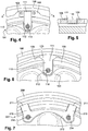
figure 3 est une vue de face partielle d'une jante d'aéronef selon un deuxième mode particulier de réalisation de l'invention; - La
figure 4 est une vue de face partielle d'une jante d'aéronef selon une variante de réalisation du deuxième mode de réalisation de l'invention; - La
figure 5 est une vue en coupe selon la ligne AA de lafigure 4 - La
figure 6 est une vue de face partielle d'une jante d'aéronef selon une autre variante du deuxième mode particulier de réalisation de l'invention; - La
figure 7 est une vue de face partielle d'une jante d'aéronef selon un troisième mode particulier de réalisation de l'invention; - En référence aux
figures 1 et 2 , l'invention s'applique à une jante d'aéronef 1 comportant un moyeu 2 destiné à recevoir des roulements pour le guidage en rotation de la jante sur un essieu d'atterrisseur d'aéronef autour d'un axe de rotation. Le moyeu 2 est relié par un voile 3 dont on aperçoit les creux et les branches à une portion externe annulaire 4 destinée à recevoir un pneumatique (non représenté ici). La portion externe annulaire 4 est terminée à l'une de ses extrémités par un talon 5 venu de matière. L'ensemble forme la partie principale de la jante. Elle est complétée par une portion amovible, en l'occurrence un talon amovible 6 qui est rapporté sur l'autre extrémité de la portion externe annulaire et que l'on peut retirer pour permettre le montage d'un pneumatique. Le talon amovible 6 est rapporté sur la jante avec interposition d'un jonc 7 bloquant axialement le talon et empêchant son extraction sous l'effet de la pression du pneumatique. Un joint d'étanchéité 8 est interposé entre la jante 1 et le talon amovible 6 pour permettre le gonflage du pneumatique. La partie principale, que l'on nommera ici jante pour simplifier la description, et le talon amovible sont ici réalisés en alliage d'aluminium. - Selon l'invention, le talon amovible 6 est arrêté en rotation sur la jante 1 au moyen d'une clavette 10 ayant d'une part une tête 11 engagée dans un réceptacle du talon amovible 6 délimité latéralement par des butées 9, et d'autre part un pied 12 se terminant ici par deux oreilles 13 percées. Ici, les oreilles 13 sont enfilées sur des pions 14 en acier qui sont engagés dans des orifices 15 de la jante 1 débouchant qui s'étendent parallèlement à l'axe de rotation de la jante. Les pions 14 ont une extrémité interne évasée 16 qui vient en appui contre un épaulement 18 de l'orifice 15 pour son arrêt axial. Les pions 14 sont frettés dans l'extrémité des orifices 16 pour saillir de la jante 1 et recevoir les oreilles du pied de la clavette 10.
- Ainsi positionnée, la clavette 10 s'oppose à toute rotation du talon amovible 6 sur la jante 1. Les clavettes 10 sont immobilisées au moyen de vis 17 vissées dans un taraudage du pion 14 et retenant une rondelle d'arrêt 19 qui immobilise axialement l'oreille 13 de la clavette 10 enfilée sur le pion 14 en laissant un léger jeu axial pour permettre à la clavette 10 un léger mouvement axial afin d'accommoder des jeux de montage ou des déformations du talon amovible 6.
- Selon un aspect particulièrement avantageux, les orifices 16 servent par ailleurs à recevoir le doigt terminal d'une barrette 20 servant à entraîner en rotation avec la jante des disques rotors de frein (non représentés) qui s'étendent à l'intérieur de la jante. Ainsi, il suffit juste de prolonger l'orifice 16 pour le faire déboucher sur la face latérale de la jante, pour lui permettre de recevoir un pion fretté 14. Aucun orifice taraudé additionnel n'est à prévoir sur la jante pour fixer le pied de la clavette 10 sur la jante.
- Selon un deuxième mode particulier de réalisation illustré à la
figure 3 sur laquelle les références des éléments similaires ont été augmentés d'une centaine, la clavette 110 comporte maintenant un pied 112 droit percé s'enfilant directement sur l'un des pions frettés 114 saillant de la jante 101. Ici l'extrémité du pion 114 a été filetée pour recevoir un écrou 121 d'arrêt axial de la clavette 110. - Selon une première variante représentée aux
figures 4 et 5 , on interpose entre les butées 109 du réceptacle du talon amovible 106 un insert en bonze 122 qui s'étend entre la tête 111 de la clavette 110 et les butées 109 pour protéger celle-ci contre le matage. - Selon une deuxième variante représentée à la
figure 6 , la clavette 110 comporte une tête 111 munie d'un chapeau 123 qui vient coiffer le dessus des butées 109 afin d'obtenir un effet auto-serrant entre la clavette fixée au pion 114 et le talon amovible 106 au cas où celui-ci aurait tendance à tourner relativement à la jante. - Selon enfin un troisième mode particulier de réalisation illustré à la
figure 7 sur laquelle les références des éléments similaires ont été encore augmentés d'une centaine, les clavettes 210, qui comportent chacune des têtes 211 coopérant avec le talon amovible 206, sont ici groupées par paires, chacune des paires partageant un pied commun 212 qui est rapporté sur deux pions 214. - L'invention n'est pas limitée à ce qui vient d'être décrit mais englobe au contraire toute variante entrant dans le cadre défini par les revendications.
- En particulier, bien qu'on ait indiqué que les pions 14,114,214 soient de préférence positionnés et frettés dans les orifices qui par ailleurs reçoivent les barrettes d'entraînement en rotation des disques rotors des freins, il est bien entendu possible, notamment si la jante n'est pas destinée à équiper une roue freinée, de prévoir des orifices spécifiques usinés dans la jante pour recevoir les pions.
- On pourra bien entendu prévoir plusieurs clavettes pour arrêter le talon amovible en rotation, par exemple trois clavettes disposées à 120 degrés l'une de l'autre.
Claims (8)
- Jante (1;101;201) de roue d'aéronef en alliage d'aluminium réalisée en deux parties dont une partie principale et une partie amovible, la partie principale comportant un moyeu (2), un voile (3) s'étendant entre le moyeu et une portion externe annulaire (4) destinée à recevoir un pneumatique et conformée pour présenter un talon (5) à l'une de ses extrémités, l'autre de ses extrémités étant conformée pour recevoir la partie amovible (6) formant talon amovible qui est rapporté sur la portion externe annulaire après mise en place du pneumatique, la jante comportant des moyens de blocage (10;110;210) en rotation du talon amovible relativement à la jante, caractérisé en ce que les moyens de blocage comportent au moins une clavette (10;110;210) ayant une tête (11 ;111 ;211) engagée dans un réceptacle conforme du talon amovible et un pied (12;112;212) fixé au moyen d'au moins un pion (14;114;214) en acier fretté dans la jante et s'étendant parallèlement à un axe de rotation de la roue pour saillir de la jante et recevoir le pied de la clavette.
- Jante selon la revendication 1, dans laquelle le pion (14) est engagé dans un orifice (15) de la jante s'étendant parallèlement à un axe de rotation de la jante.
- Jante selon la revendication 2, équipée de barrettes (20) d'entraînement en rotation de disques rotors de freins, chaque barrette ayant un doigt d'extrémité engagé dans l'un des orifices (15) recevant l'un des pions (14).
- Jante selon la revendication 1, dans lequel le pied (12) de la clavette s'étend pour présenter deux oreilles (13) chacune engagée sur l'un des pions (14).
- Jante selon la revendication 1, dans lequel le pied (112) de la clavette est engagé sur un pion (114).
- Jante selon la revendication 1, dans lequel un insert en bronze (122) est interposé entre la tête (111) de la clavette et le réceptacle du talon amovible (106).
- Jante selon la revendication 1, dans lequel la tête (111) de la clavette (110) comporte un chapeau (123).
- Jante selon la revendication 1, dans lequel les clavettes (210) sont groupées par paires, chaque paire comportant un pied commun (211) engagé sur deux pions (214).
Applications Claiming Priority (1)
| Application Number | Priority Date | Filing Date | Title |
|---|---|---|---|
| FR1661717A FR3059270B1 (fr) | 2016-11-30 | 2016-11-30 | Roue d'aeronef a talon amovible |
Publications (2)
| Publication Number | Publication Date |
|---|---|
| EP3332985A1 true EP3332985A1 (fr) | 2018-06-13 |
| EP3332985B1 EP3332985B1 (fr) | 2019-09-11 |
Family
ID=57796697
Family Applications (1)
| Application Number | Title | Priority Date | Filing Date |
|---|---|---|---|
| EP17203995.0A Active EP3332985B1 (fr) | 2016-11-30 | 2017-11-28 | Roue d'aeronef a talon amovible |
Country Status (4)
| Country | Link |
|---|---|
| US (1) | US11305578B2 (fr) |
| EP (1) | EP3332985B1 (fr) |
| CN (1) | CN108116157B (fr) |
| FR (1) | FR3059270B1 (fr) |
Families Citing this family (5)
| Publication number | Priority date | Publication date | Assignee | Title |
|---|---|---|---|---|
| FR3093321B1 (fr) * | 2019-02-28 | 2021-06-18 | Safran Landing Systems | Roue d’aéronef pourvue d’écrans thermiques |
| CN111421999A (zh) * | 2020-04-10 | 2020-07-17 | 徐超 | 一种轮辋及车轮 |
| US11833852B2 (en) * | 2020-08-21 | 2023-12-05 | Caterpillar Inc. | Lock for wheel rim and assemblies, systems, and methods thereof |
| US11697307B2 (en) * | 2020-12-04 | 2023-07-11 | The Goodyear Tire & Rubber Company | Wheel for a support structure |
| USD1048858S1 (en) * | 2023-02-14 | 2024-10-29 | Otr Wheel Engineering, Inc. | Wheel assembly lock key |
Citations (3)
| Publication number | Priority date | Publication date | Assignee | Title |
|---|---|---|---|---|
| DE3630226A1 (de) * | 1985-09-12 | 1987-03-19 | Dieter Wipperfuerth | Mindestens zweiteiliges leichtmetallrad fuer luftbereifte kraftfahrzeuge mit verbindung durch druckbelastung |
| US20070227639A1 (en) * | 2006-04-03 | 2007-10-04 | Cortes Juan J | Vehicular wheel and method of forming the same |
| FR3015951A1 (fr) * | 2013-12-31 | 2015-07-03 | Messier Bugatti Dowty | Jante de roue d'aeronef a talon amovible. |
Family Cites Families (10)
| Publication number | Priority date | Publication date | Assignee | Title |
|---|---|---|---|---|
| US1880641A (en) * | 1929-03-20 | 1932-10-04 | Goodyear Tire & Rubber | Vehicle wheel |
| US2523756A (en) * | 1944-12-18 | 1950-09-26 | Bendix Aviat Corp | Wheel structure |
| US3224484A (en) * | 1964-04-22 | 1965-12-21 | Le Tourneau Westinghouse Compa | Wheel construction |
| US3529869A (en) * | 1968-08-26 | 1970-09-22 | Caterpillar Tractor Co | Drive means in pneumatic tire rim |
| US4046184A (en) * | 1974-08-02 | 1977-09-06 | Diehl John A | Safety means for preventing demounting of low or flat tires from vehicle wheels |
| US4043373A (en) * | 1975-11-05 | 1977-08-23 | Roger Owen Durham | Rim strip for bicycle wheels |
| US4084857A (en) * | 1976-12-20 | 1978-04-18 | The Bendix Corporation | Drive key heat shield and support for wheel rim heat shield of multiple disc brake |
| GB2009662B (en) * | 1977-12-09 | 1982-06-23 | Dunlop Ltd | Wheel rims |
| US5086821A (en) * | 1990-01-23 | 1992-02-11 | The B. F. Goodrich Company | Aircraft wheel |
| US9604498B2 (en) * | 2014-02-04 | 2017-03-28 | Arconic Inc. | Wheel assembly |
-
2016
- 2016-11-30 FR FR1661717A patent/FR3059270B1/fr not_active Expired - Fee Related
-
2017
- 2017-11-28 EP EP17203995.0A patent/EP3332985B1/fr active Active
- 2017-11-28 CN CN201711214951.9A patent/CN108116157B/zh active Active
- 2017-11-29 US US15/826,564 patent/US11305578B2/en active Active
Patent Citations (3)
| Publication number | Priority date | Publication date | Assignee | Title |
|---|---|---|---|---|
| DE3630226A1 (de) * | 1985-09-12 | 1987-03-19 | Dieter Wipperfuerth | Mindestens zweiteiliges leichtmetallrad fuer luftbereifte kraftfahrzeuge mit verbindung durch druckbelastung |
| US20070227639A1 (en) * | 2006-04-03 | 2007-10-04 | Cortes Juan J | Vehicular wheel and method of forming the same |
| FR3015951A1 (fr) * | 2013-12-31 | 2015-07-03 | Messier Bugatti Dowty | Jante de roue d'aeronef a talon amovible. |
Also Published As
| Publication number | Publication date |
|---|---|
| CN108116157A (zh) | 2018-06-05 |
| FR3059270A1 (fr) | 2018-06-01 |
| FR3059270B1 (fr) | 2019-05-10 |
| US20180147885A1 (en) | 2018-05-31 |
| EP3332985B1 (fr) | 2019-09-11 |
| US11305578B2 (en) | 2022-04-19 |
| CN108116157B (zh) | 2021-11-12 |
Similar Documents
| Publication | Publication Date | Title |
|---|---|---|
| EP3332985B1 (fr) | Roue d'aeronef a talon amovible | |
| CA2808342C (fr) | Dispositif de securite pour une roue d'un vehicule | |
| CA2835921A1 (fr) | Roue d'aeronef equipee de boulons-barrettes | |
| EP2338776A1 (fr) | Jeu de direction de cycle à goupille et cycle comportant un tel jeu de direction | |
| FR2992677A1 (fr) | Moyeu pour logement radial d'anneau d'helice de turbomachine a pales a calage variable et assemblage comportant un tel moyeu | |
| EP2402538A1 (fr) | Vérin à vis pour la manoeuvre d'un ouvrant de véhicule | |
| EP2745887B1 (fr) | Fixation de chaussure sur équipement sportif | |
| EP2873611B1 (fr) | Roue d'aéronef équipée de moyens de son entraînement en rotation par un actionneur d'entraînement | |
| FR3045752A1 (fr) | Etrier de frein a disque equipe d'une plaque protectrice portant des taquets rotatifs de fixation au corps d'etrier | |
| FR2653069A1 (fr) | Procede de fixation rapide et sure de rayons droits sur un moyeu de roue de cycle. | |
| EP0615904B1 (fr) | Tête de rotor pour giravion | |
| EP2597230B1 (fr) | Cylindre de serrure de sûreté | |
| CA3142457C (fr) | Dispositif de fixation par vissage, avec freinage a l'etat visse | |
| EP2780220B1 (fr) | Dispositif d'actionnement d'un câble de frein de vélo | |
| EP1975748B1 (fr) | Boîte de montre-bracelet | |
| EP0114549B1 (fr) | Frein à disque | |
| FR2499648A1 (fr) | Dispositif de fixation pour une broche de guidage d'un frein a disque a etrier flottant | |
| EP4437244B1 (fr) | Système de freinage ferroviaire pour véhicule ferroviaire, à freins à au moins un sabot, et véhicule ferroviaire pourvu d'un tel système | |
| CA3142457A1 (fr) | Dispositif de fixation par vissage, avec freinage a l'etat visse | |
| FR2549000A1 (fr) | Pedale en matiere plastique pour bicyclettes ou similaires | |
| EP2873610B1 (fr) | Roue d'aéronef équipée d'une couronne d'entraînement à chaîne | |
| BE1007764A4 (fr) | Montage de nacelle pour manege. | |
| FR2841924A1 (fr) | Poignee de porte, et dispositif pour sa fixation | |
| CH720438A2 (fr) | Boîte de montre comprenant une lunette tournante amovible | |
| EP1083376A1 (fr) | Collier de serrage à vis tangente |
Legal Events
| Date | Code | Title | Description |
|---|---|---|---|
| PUAI | Public reference made under article 153(3) epc to a published international application that has entered the european phase |
Free format text: ORIGINAL CODE: 0009012 |
|
| STAA | Information on the status of an ep patent application or granted ep patent |
Free format text: STATUS: THE APPLICATION HAS BEEN PUBLISHED |
|
| AK | Designated contracting states |
Kind code of ref document: A1 Designated state(s): AL AT BE BG CH CY CZ DE DK EE ES FI FR GB GR HR HU IE IS IT LI LT LU LV MC MK MT NL NO PL PT RO RS SE SI SK SM TR |
|
| AX | Request for extension of the european patent |
Extension state: BA ME |
|
| STAA | Information on the status of an ep patent application or granted ep patent |
Free format text: STATUS: REQUEST FOR EXAMINATION WAS MADE |
|
| 17P | Request for examination filed |
Effective date: 20181211 |
|
| RBV | Designated contracting states (corrected) |
Designated state(s): AL AT BE BG CH CY CZ DE DK EE ES FI FR GB GR HR HU IE IS IT LI LT LU LV MC MK MT NL NO PL PT RO RS SE SI SK SM TR |
|
| GRAP | Despatch of communication of intention to grant a patent |
Free format text: ORIGINAL CODE: EPIDOSNIGR1 |
|
| STAA | Information on the status of an ep patent application or granted ep patent |
Free format text: STATUS: GRANT OF PATENT IS INTENDED |
|
| INTG | Intention to grant announced |
Effective date: 20190405 |
|
| GRAS | Grant fee paid |
Free format text: ORIGINAL CODE: EPIDOSNIGR3 |
|
| GRAA | (expected) grant |
Free format text: ORIGINAL CODE: 0009210 |
|
| STAA | Information on the status of an ep patent application or granted ep patent |
Free format text: STATUS: THE PATENT HAS BEEN GRANTED |
|
| AK | Designated contracting states |
Kind code of ref document: B1 Designated state(s): AL AT BE BG CH CY CZ DE DK EE ES FI FR GB GR HR HU IE IS IT LI LT LU LV MC MK MT NL NO PL PT RO RS SE SI SK SM TR |
|
| REG | Reference to a national code |
Ref country code: GB Ref legal event code: FG4D Free format text: NOT ENGLISH |
|
| REG | Reference to a national code |
Ref country code: CH Ref legal event code: EP |
|
| REG | Reference to a national code |
Ref country code: AT Ref legal event code: REF Ref document number: 1177955 Country of ref document: AT Kind code of ref document: T Effective date: 20190915 |
|
| REG | Reference to a national code |
Ref country code: DE Ref legal event code: R096 Ref document number: 602017006962 Country of ref document: DE Ref country code: IE Ref legal event code: FG4D Free format text: LANGUAGE OF EP DOCUMENT: FRENCH |
|
| REG | Reference to a national code |
Ref country code: NL Ref legal event code: MP Effective date: 20190911 |
|
| REG | Reference to a national code |
Ref country code: LT Ref legal event code: MG4D |
|
| PG25 | Lapsed in a contracting state [announced via postgrant information from national office to epo] |
Ref country code: FI Free format text: LAPSE BECAUSE OF FAILURE TO SUBMIT A TRANSLATION OF THE DESCRIPTION OR TO PAY THE FEE WITHIN THE PRESCRIBED TIME-LIMIT Effective date: 20190911 Ref country code: NO Free format text: LAPSE BECAUSE OF FAILURE TO SUBMIT A TRANSLATION OF THE DESCRIPTION OR TO PAY THE FEE WITHIN THE PRESCRIBED TIME-LIMIT Effective date: 20191211 Ref country code: HR Free format text: LAPSE BECAUSE OF FAILURE TO SUBMIT A TRANSLATION OF THE DESCRIPTION OR TO PAY THE FEE WITHIN THE PRESCRIBED TIME-LIMIT Effective date: 20190911 Ref country code: BG Free format text: LAPSE BECAUSE OF FAILURE TO SUBMIT A TRANSLATION OF THE DESCRIPTION OR TO PAY THE FEE WITHIN THE PRESCRIBED TIME-LIMIT Effective date: 20191211 Ref country code: SE Free format text: LAPSE BECAUSE OF FAILURE TO SUBMIT A TRANSLATION OF THE DESCRIPTION OR TO PAY THE FEE WITHIN THE PRESCRIBED TIME-LIMIT Effective date: 20190911 Ref country code: LT Free format text: LAPSE BECAUSE OF FAILURE TO SUBMIT A TRANSLATION OF THE DESCRIPTION OR TO PAY THE FEE WITHIN THE PRESCRIBED TIME-LIMIT Effective date: 20190911 |
|
| PG25 | Lapsed in a contracting state [announced via postgrant information from national office to epo] |
Ref country code: LV Free format text: LAPSE BECAUSE OF FAILURE TO SUBMIT A TRANSLATION OF THE DESCRIPTION OR TO PAY THE FEE WITHIN THE PRESCRIBED TIME-LIMIT Effective date: 20190911 Ref country code: AL Free format text: LAPSE BECAUSE OF FAILURE TO SUBMIT A TRANSLATION OF THE DESCRIPTION OR TO PAY THE FEE WITHIN THE PRESCRIBED TIME-LIMIT Effective date: 20190911 Ref country code: RS Free format text: LAPSE BECAUSE OF FAILURE TO SUBMIT A TRANSLATION OF THE DESCRIPTION OR TO PAY THE FEE WITHIN THE PRESCRIBED TIME-LIMIT Effective date: 20190911 Ref country code: GR Free format text: LAPSE BECAUSE OF FAILURE TO SUBMIT A TRANSLATION OF THE DESCRIPTION OR TO PAY THE FEE WITHIN THE PRESCRIBED TIME-LIMIT Effective date: 20191212 Ref country code: ES Free format text: LAPSE BECAUSE OF FAILURE TO SUBMIT A TRANSLATION OF THE DESCRIPTION OR TO PAY THE FEE WITHIN THE PRESCRIBED TIME-LIMIT Effective date: 20190911 |
|
| REG | Reference to a national code |
Ref country code: AT Ref legal event code: MK05 Ref document number: 1177955 Country of ref document: AT Kind code of ref document: T Effective date: 20190911 |
|
| PG25 | Lapsed in a contracting state [announced via postgrant information from national office to epo] |
Ref country code: RO Free format text: LAPSE BECAUSE OF FAILURE TO SUBMIT A TRANSLATION OF THE DESCRIPTION OR TO PAY THE FEE WITHIN THE PRESCRIBED TIME-LIMIT Effective date: 20190911 Ref country code: IT Free format text: LAPSE BECAUSE OF FAILURE TO SUBMIT A TRANSLATION OF THE DESCRIPTION OR TO PAY THE FEE WITHIN THE PRESCRIBED TIME-LIMIT Effective date: 20190911 Ref country code: PL Free format text: LAPSE BECAUSE OF FAILURE TO SUBMIT A TRANSLATION OF THE DESCRIPTION OR TO PAY THE FEE WITHIN THE PRESCRIBED TIME-LIMIT Effective date: 20190911 Ref country code: PT Free format text: LAPSE BECAUSE OF FAILURE TO SUBMIT A TRANSLATION OF THE DESCRIPTION OR TO PAY THE FEE WITHIN THE PRESCRIBED TIME-LIMIT Effective date: 20200113 Ref country code: NL Free format text: LAPSE BECAUSE OF FAILURE TO SUBMIT A TRANSLATION OF THE DESCRIPTION OR TO PAY THE FEE WITHIN THE PRESCRIBED TIME-LIMIT Effective date: 20190911 Ref country code: EE Free format text: LAPSE BECAUSE OF FAILURE TO SUBMIT A TRANSLATION OF THE DESCRIPTION OR TO PAY THE FEE WITHIN THE PRESCRIBED TIME-LIMIT Effective date: 20190911 Ref country code: AT Free format text: LAPSE BECAUSE OF FAILURE TO SUBMIT A TRANSLATION OF THE DESCRIPTION OR TO PAY THE FEE WITHIN THE PRESCRIBED TIME-LIMIT Effective date: 20190911 |
|
| PG25 | Lapsed in a contracting state [announced via postgrant information from national office to epo] |
Ref country code: CZ Free format text: LAPSE BECAUSE OF FAILURE TO SUBMIT A TRANSLATION OF THE DESCRIPTION OR TO PAY THE FEE WITHIN THE PRESCRIBED TIME-LIMIT Effective date: 20190911 Ref country code: SM Free format text: LAPSE BECAUSE OF FAILURE TO SUBMIT A TRANSLATION OF THE DESCRIPTION OR TO PAY THE FEE WITHIN THE PRESCRIBED TIME-LIMIT Effective date: 20190911 Ref country code: IS Free format text: LAPSE BECAUSE OF FAILURE TO SUBMIT A TRANSLATION OF THE DESCRIPTION OR TO PAY THE FEE WITHIN THE PRESCRIBED TIME-LIMIT Effective date: 20200224 Ref country code: SK Free format text: LAPSE BECAUSE OF FAILURE TO SUBMIT A TRANSLATION OF THE DESCRIPTION OR TO PAY THE FEE WITHIN THE PRESCRIBED TIME-LIMIT Effective date: 20190911 |
|
| REG | Reference to a national code |
Ref country code: DE Ref legal event code: R097 Ref document number: 602017006962 Country of ref document: DE |
|
| PLBE | No opposition filed within time limit |
Free format text: ORIGINAL CODE: 0009261 |
|
| STAA | Information on the status of an ep patent application or granted ep patent |
Free format text: STATUS: NO OPPOSITION FILED WITHIN TIME LIMIT |
|
| PG2D | Information on lapse in contracting state deleted |
Ref country code: IS |
|
| PG25 | Lapsed in a contracting state [announced via postgrant information from national office to epo] |
Ref country code: MC Free format text: LAPSE BECAUSE OF FAILURE TO SUBMIT A TRANSLATION OF THE DESCRIPTION OR TO PAY THE FEE WITHIN THE PRESCRIBED TIME-LIMIT Effective date: 20190911 Ref country code: LU Free format text: LAPSE BECAUSE OF NON-PAYMENT OF DUE FEES Effective date: 20191128 Ref country code: DK Free format text: LAPSE BECAUSE OF FAILURE TO SUBMIT A TRANSLATION OF THE DESCRIPTION OR TO PAY THE FEE WITHIN THE PRESCRIBED TIME-LIMIT Effective date: 20190911 Ref country code: IS Free format text: LAPSE BECAUSE OF FAILURE TO SUBMIT A TRANSLATION OF THE DESCRIPTION OR TO PAY THE FEE WITHIN THE PRESCRIBED TIME-LIMIT Effective date: 20200112 |
|
| 26N | No opposition filed |
Effective date: 20200615 |
|
| REG | Reference to a national code |
Ref country code: BE Ref legal event code: MM Effective date: 20191130 |
|
| PG25 | Lapsed in a contracting state [announced via postgrant information from national office to epo] |
Ref country code: SI Free format text: LAPSE BECAUSE OF FAILURE TO SUBMIT A TRANSLATION OF THE DESCRIPTION OR TO PAY THE FEE WITHIN THE PRESCRIBED TIME-LIMIT Effective date: 20190911 |
|
| PG25 | Lapsed in a contracting state [announced via postgrant information from national office to epo] |
Ref country code: IE Free format text: LAPSE BECAUSE OF NON-PAYMENT OF DUE FEES Effective date: 20191128 |
|
| PG25 | Lapsed in a contracting state [announced via postgrant information from national office to epo] |
Ref country code: BE Free format text: LAPSE BECAUSE OF NON-PAYMENT OF DUE FEES Effective date: 20191130 |
|
| PG25 | Lapsed in a contracting state [announced via postgrant information from national office to epo] |
Ref country code: CY Free format text: LAPSE BECAUSE OF FAILURE TO SUBMIT A TRANSLATION OF THE DESCRIPTION OR TO PAY THE FEE WITHIN THE PRESCRIBED TIME-LIMIT Effective date: 20190911 |
|
| REG | Reference to a national code |
Ref country code: CH Ref legal event code: PL |
|
| PG25 | Lapsed in a contracting state [announced via postgrant information from national office to epo] |
Ref country code: HU Free format text: LAPSE BECAUSE OF FAILURE TO SUBMIT A TRANSLATION OF THE DESCRIPTION OR TO PAY THE FEE WITHIN THE PRESCRIBED TIME-LIMIT; INVALID AB INITIO Effective date: 20171128 Ref country code: MT Free format text: LAPSE BECAUSE OF FAILURE TO SUBMIT A TRANSLATION OF THE DESCRIPTION OR TO PAY THE FEE WITHIN THE PRESCRIBED TIME-LIMIT Effective date: 20190911 |
|
| PG25 | Lapsed in a contracting state [announced via postgrant information from national office to epo] |
Ref country code: LI Free format text: LAPSE BECAUSE OF NON-PAYMENT OF DUE FEES Effective date: 20201130 Ref country code: CH Free format text: LAPSE BECAUSE OF NON-PAYMENT OF DUE FEES Effective date: 20201130 |
|
| PG25 | Lapsed in a contracting state [announced via postgrant information from national office to epo] |
Ref country code: TR Free format text: LAPSE BECAUSE OF FAILURE TO SUBMIT A TRANSLATION OF THE DESCRIPTION OR TO PAY THE FEE WITHIN THE PRESCRIBED TIME-LIMIT Effective date: 20190911 |
|
| PG25 | Lapsed in a contracting state [announced via postgrant information from national office to epo] |
Ref country code: MK Free format text: LAPSE BECAUSE OF FAILURE TO SUBMIT A TRANSLATION OF THE DESCRIPTION OR TO PAY THE FEE WITHIN THE PRESCRIBED TIME-LIMIT Effective date: 20190911 |
|
| PGFP | Annual fee paid to national office [announced via postgrant information from national office to epo] |
Ref country code: DE Payment date: 20251118 Year of fee payment: 9 |
|
| PGFP | Annual fee paid to national office [announced via postgrant information from national office to epo] |
Ref country code: GB Payment date: 20251125 Year of fee payment: 9 |
|
| PGFP | Annual fee paid to national office [announced via postgrant information from national office to epo] |
Ref country code: FR Payment date: 20251125 Year of fee payment: 9 |