EP3332833B1 - Katheterhalterung - Google Patents
Katheterhalterung Download PDFInfo
- Publication number
- EP3332833B1 EP3332833B1 EP16833161.9A EP16833161A EP3332833B1 EP 3332833 B1 EP3332833 B1 EP 3332833B1 EP 16833161 A EP16833161 A EP 16833161A EP 3332833 B1 EP3332833 B1 EP 3332833B1
- Authority
- EP
- European Patent Office
- Prior art keywords
- catheter
- guide hole
- fixture
- base plate
- guide
- Prior art date
- Legal status (The legal status is an assumption and is not a legal conclusion. Google has not performed a legal analysis and makes no representation as to the accuracy of the status listed.)
- Active
Links
Images




Classifications
-
- A—HUMAN NECESSITIES
- A61—MEDICAL OR VETERINARY SCIENCE; HYGIENE
- A61M—DEVICES FOR INTRODUCING MEDIA INTO, OR ONTO, THE BODY; DEVICES FOR TRANSDUCING BODY MEDIA OR FOR TAKING MEDIA FROM THE BODY; DEVICES FOR PRODUCING OR ENDING SLEEP OR STUPOR
- A61M25/00—Catheters; Hollow probes
- A61M25/01—Introducing, guiding, advancing, emplacing or holding catheters
- A61M25/02—Holding devices, e.g. on the body
-
- A—HUMAN NECESSITIES
- A61—MEDICAL OR VETERINARY SCIENCE; HYGIENE
- A61J—CONTAINERS SPECIALLY ADAPTED FOR MEDICAL OR PHARMACEUTICAL PURPOSES; DEVICES OR METHODS SPECIALLY ADAPTED FOR BRINGING PHARMACEUTICAL PRODUCTS INTO PARTICULAR PHYSICAL OR ADMINISTERING FORMS; DEVICES FOR ADMINISTERING FOOD OR MEDICINES ORALLY; BABY COMFORTERS; DEVICES FOR RECEIVING SPITTLE
- A61J15/00—Feeding-tubes for therapeutic purposes
- A61J15/0026—Parts, details or accessories for feeding-tubes
- A61J15/0053—Means for fixing the tube outside of the body, e.g. by a special shape, by fixing it to the skin
-
- A—HUMAN NECESSITIES
- A61—MEDICAL OR VETERINARY SCIENCE; HYGIENE
- A61J—CONTAINERS SPECIALLY ADAPTED FOR MEDICAL OR PHARMACEUTICAL PURPOSES; DEVICES OR METHODS SPECIALLY ADAPTED FOR BRINGING PHARMACEUTICAL PRODUCTS INTO PARTICULAR PHYSICAL OR ADMINISTERING FORMS; DEVICES FOR ADMINISTERING FOOD OR MEDICINES ORALLY; BABY COMFORTERS; DEVICES FOR RECEIVING SPITTLE
- A61J15/00—Feeding-tubes for therapeutic purposes
- A61J15/0015—Gastrostomy feeding-tubes
-
- A—HUMAN NECESSITIES
- A61—MEDICAL OR VETERINARY SCIENCE; HYGIENE
- A61M—DEVICES FOR INTRODUCING MEDIA INTO, OR ONTO, THE BODY; DEVICES FOR TRANSDUCING BODY MEDIA OR FOR TAKING MEDIA FROM THE BODY; DEVICES FOR PRODUCING OR ENDING SLEEP OR STUPOR
- A61M25/00—Catheters; Hollow probes
- A61M25/01—Introducing, guiding, advancing, emplacing or holding catheters
- A61M25/02—Holding devices, e.g. on the body
- A61M2025/024—Holding devices, e.g. on the body having a clip or clamp system
-
- A—HUMAN NECESSITIES
- A61—MEDICAL OR VETERINARY SCIENCE; HYGIENE
- A61M—DEVICES FOR INTRODUCING MEDIA INTO, OR ONTO, THE BODY; DEVICES FOR TRANSDUCING BODY MEDIA OR FOR TAKING MEDIA FROM THE BODY; DEVICES FOR PRODUCING OR ENDING SLEEP OR STUPOR
- A61M25/00—Catheters; Hollow probes
- A61M25/01—Introducing, guiding, advancing, emplacing or holding catheters
- A61M25/02—Holding devices, e.g. on the body
- A61M2025/028—Holding devices, e.g. on the body having a mainly rigid support structure
Definitions
- the present invention relates to a catheter fixture and, more particularly, to a catheter fixture for fixing a catheter to the body of a patient.
- a catheter which is a kind of medical tubes, is widely used as a general name of tube-shaped instruments.
- catheters comprised of various materials and having various sizes and shapes for the usages.
- Such catheters may be used to extract retained substances in a body cavity or in various organs, absorb cleansing perfusate, measure the status of cardiac blood flow or central venous pressure, inject medicines or contrast media into a body, etc.
- a Percutaneous Endoscopic Gastrostomy (PEG) tube which is a kind of catheter, is a soft silicon tube designed to be inserted into the stomach through the abdomen and has an open port at the end thereof so that food can be injected. Further, as shown in FIG. 1 , a fixture is combined with a PEG tube and guides the PEG tube in close contact with the skin of a patient.
- PEG Percutaneous Endoscopic Gastrostomy
- a catheter is maintained perpendicular to the body of a patient to inject food or medicine, and then it is bent at a right angle in any direction and then attached to the body of the patient by an adhesive band etc. to be stowed.
- the adhesive band is detached and then food or medicine is injected and catheters are managed in this way.
- a catheter attached to the body of a patient may be separated from the body of the patient when an adhesive band is detached.
- stomach wall and the inner fixture (not shown) of a catheter are usually slightly spaced from each other to prevent pressure that may be applied to the stomach wall, but when an adhesive such as an adhesive band is used, the danger that the catheter and the inner fixture are vertically pulled and press the stomach wall due to carelessness is increased.
- US 5 374 254 A discloses a catheter fixture comprising a base plate having a base hole for passing a catheter.
- JP H08 38616 A , US 5 267 969 A , US 4 834 712 A and US 2010/324491 A1 disclose a catheter fixture with guide hole.
- the present invention has been made in an effort to solve the problems in the related art and an object of the present invention is to prevent backflow of food or medicine using a fixture for fixing a catheter.
- Another object of the present invention is to keep a catheter bent in parallel with the skin of a patient using a catheter fixture even without using a specific adhesive such as an adhesive band.
- an aspect of the present invention provides a catheter fixture includes: a base plate having a base hole for passing a catheter; and a fixture body formed on a top of the base plate, and the fixture body having a first guide hole connected to the base hole, extending in an open direction of the base hole, and guiding the catheter, and a second guide hole extending in a different direction from the first guide hole and guiding the catheter, wherein the fixture body has a guide fence protruding upward from a side of the base plate and a cover disposed at a side of the guide fence and forming the second guide hole therein, the first guide hole is formed between the guide fence and the cover, and wherein the cover protrudes upward from the base plate with an end directed back toward the base plate and a space is defined between the end directed toward the base plate and the base plate such that the second guide hole is laterally open.
- the second guide hole may extend perpendicular to the first guide hole.
- the second guide hole may gradually decline as the second guide hole goes away from an end connected to the base hole.
- the base plate and the fixture body may be integrally made of an elastic material.
- a third guide hole having a diameter different from the second guide hole may be formed through the guide fence to be open opposite to the second guide hole.
- the catheter fixture according to the present invention has the following effects.
- first guide hole and the second guide hole are formed in different directions in the catheter fixture, a user can extend the catheter in different directions, if necessary.
- a user can guide a catheter vertically (through the first hole) when injecting food or medicine through the catheter, that is, guide a catheter in the insertion direction into the body of a patient, and can guide a portion of the catheter at a right angle (through the second guide hole) to prevent backflow after finishing injection. Accordingly, it is possible to more stably and simply prevent backflow of food or medicine, using one catheter fixture without a specific component, thereby improving convenience.
- the second guide hole of the catheter fixture gradually declines, it is possible to further reduce the possibility of backflow through a catheter. Further, since a side of the cover of the catheter fixture is open, it is possible to easily insert and take a catheter into and out of the second guide hole.
- the catheter fixture of the present invention it is possible to stow a catheter at a right angle when not injecting food or medicine through the catheter, so there is no need to use a separate adhesive such as an adhesive band. Accordingly, it is possible to more easily manage a catheter, improve sanitation, and prevent the possibility of excessive pressure on the body of a patient when detaching an adhesive, so stability is also improved.
- terms 'first', 'second', 'A', 'B', '(a)', and '(b)' can be used in the following description of embodiments of the present invention. The terms are provided only for discriminating components from other components, and the essence, sequence, or order of the components are not limited by the terms.
- a component is described as being “connected”, “combined”, or “coupled” with another component, it should be understood that the component may be connected or coupled to another component directly or with another component interposing therebetween.
- a catheter fixture for a PEG tube of catheters T is exemplified in the following description. Obviously, the catheter T according to the present invention may be applied all of various catheters T.
- the catheter T which is a kind of medical tube, is made of a flexible material such that a portion is inserted into the body of a patient and the other portion is left outside the body.
- a syringe etc. is connected to the portion of the catheter T left outside the body of the patient to inject medicine or food into the body through the catheter T.
- a catheter fixture is combined with the catheter T.
- the catheter fixture allows the catheter T to be fixed to a portion of the body of a patient and they may be combined by fitting the catheter T through the fixture.
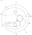
- the catheter fixture is clearly shown in the perspective view of FIG. 2 .
- the frame of the catheter fixture is formed by a base plate 10.
- the base plate 10 is a substantially thin plate and is a part to be actually brought in contact with the skin of a patient. Obviously, a gauze etc. may be inserted between the base plate 10 and the skin of a patient.
- the base plate 10 is a circular plate, it is not limited thereto and may be formed in various shapes of plates such as an ellipse or a polygon.
- a base hole BH is formed through the base plate 10.
- the base hole BH which is a part through which the catheter T passes, has an inner diameter the same as or larger than the outer diameter of the catheter T.
- the base hole BH is formed vertically through the base plate 10.
- the fixture body 20 is formed on the top of the base plate 10.
- the fixture body 20 is integrally formed with the base plate 10, protruding at a predetermined height from the base plate 10. That is, the base plate 10 and the fixture body 20 are made of the same material in one unit, and they are made of silicon.
- the catheter fixture may be made of flexible materials such as silicon.
- the fixture body 20 has a guide fence 25 at a side.
- the guide fence 25 protrudes upward from a side of the base plate 10.
- the guide fence 25 supports a side of the catheter T extending vertically through a first guide hole GH1 to be described below or moving horizontally through a second guide hole GH2.
- the guide fence 25 is formed close to the base hole BH and the first guide hole GH1 connected to the base hole BH is vertically formed at a side of the guide fence 25. More accurately, the first guide hole GH 1 is formed between the guide fence 25 and a cover 30 to be described below.
- the first guide hole GH1 is connected to the base hole BH and extends in the open direction of the base hole BH1, so, as shown in FIG. 7 , when the catheter T passes through the first guide hole GH1, the catheter T can extend in the insertion direction into the body of a patient. In this state, medicine or food can be injected from an end of the catheter T.
- the cover 30 is formed at a side of the guide fence 25.
- the cover 30 protrudes upward from the base plate 10 with one end directed back toward the base plate 10. That is, the cover 30 is rounded such that the outer surface curved and covers the second guide hole GH2 thereunder. As shown in FIGS. 4 and 5 , the cover 30 may continue from the guide fence 25.
- the cover 30 forms the second guide hole GH2 and holds the upper surface of the catheter T guided through the second guide hole GH2 to prevent the catheter T from separating from the second guide hole GH2. That is, the second guide hole GH2 is formed between the cover 30 and the base plate 10.
- the second guide hole GH2 gradually declines as it goes away from the end connected to the base hole BH.
- the top 35 of the cover 30 gradually declines as it goes away from the guide fence 25, so the guide hole GH2 also declines. Accordingly, the catheter T can be bent slight down from the right angle when passing through the second guide hole GH2, so backflow through the catheter T can be more stably prevented.
- the catheter T passing through the declining second guide hole GH2 is naturally guided gradually closer to the skin of a patient, so the catheter T can be easily fixed to the patient's skin.
- the arrow 1 indicates the direction in which the catheter T is guided into the second guide hole GH2 and the arrow 2 indicates the direction in which the catheter T is guided into the first guide hole GH1.
- the second guide hole GH2 is laterally open. That is, a predetermined space S is defined between the cover 30 and the fixture body 20, so a portion of the second guide hole GH2 is open to the outside. Further, a portion of the catheter T can be easily inserted into and taken out of the second guide hole GH2 through the space S.
- the catheter fixture is made of a flexible material, a user can open the second guide hole GH2 by holding and opening an end of the cover 30 upward (in FIG. 5 ) from the space S and then insert or take the catheter T into or out of the second guide hole GH2.
- a projective grip 32 is formed at a side of the cover 30.
- the projective grip 32 protrudes from a side of the cover 30 perpendicular to the longitudinal direction of the second guide hole GH2 so that a user can easily open the cover 30 by holding it.
- the guide fence 25 protrudes from the base plate 10 less than the cover 30. This is for more easily handling an end of the catheter T through the gap formed by the height difference between the cover 30 and the guide fence 25.
- a third guide hole GH3 may be formed through the guide fence 25 to be open to the outside opposite to the second guide hole GH2.
- the third guide hole GH3 allows the catheter T to extend opposite to the second guide hole GH2.
- the third guide hole GH3 may have a different diameter from the second guide hole GH2 so that the catheter fixture can be applied to catheters T having various diameters.
- Non-stated reference numeral '12' indicates through-holes formed through the base plate 10 and the fixture body. The through-holes 12 decrease the contact area between the skin of a patient and the catheter fixture and increase the contact area between the skin of a patient and air.
- a user inserts a portion of the catheter T into the body of a patient and then fixes the catheter fixture on the patient's skin.
- the catheter T exposed out of the patient's body extends through the first guide hole GH1 of the catheter fixture, that is, as shown in FIG. 7 , the catheter T extends vertically through the first guide hole GH1.
- the user blocks the first end and puts the catheter T into the second guide hole GH2.
- the cover 30 of the catheter fixture is elastically deformed and the space S between the cover 30 and the base plate 10, that is, the inlet of the second guide hole GH2 is widened, the catheter T can be easily inserted into the second guide hole GH2.
- the catheter T is partially bent at a right angle and backflow of the food or medicine can be more stably prevented at the bent portion. Further, since the catheter T extends in parallel with the patient's skin by the catheter fixture, the user can more easily fix a portion of the catheter T to the patient's skin after finishing injecting food or medicine.
- the user may fix the base plate 10 to the patient's skin using an adhesive such as an adhesive tape.
Landscapes
- Health & Medical Sciences (AREA)
- Life Sciences & Earth Sciences (AREA)
- Animal Behavior & Ethology (AREA)
- Pulmonology (AREA)
- General Health & Medical Sciences (AREA)
- Public Health (AREA)
- Veterinary Medicine (AREA)
- Engineering & Computer Science (AREA)
- Anesthesiology (AREA)
- Biomedical Technology (AREA)
- Heart & Thoracic Surgery (AREA)
- Hematology (AREA)
- Biophysics (AREA)
- Media Introduction/Drainage Providing Device (AREA)
- Infusion, Injection, And Reservoir Apparatuses (AREA)
Claims (5)
- Katheter- (T) Halterung aufweisend:eine Basisplatte (10), die ein Basisloch (BH) zum Hindurchverlaufen eines Katheters (T) aufweist, undeinen Halterungskörper (20), der an einer Oberseite der Basisplatte (10) ausgebildet ist, wobei der Halterungskörper (20) aufweist ein erstes Führungsloch (GH1), das mit dem Basisloch (BH) verbunden ist, sich in einer Öffnungsrichtung des Basislochs (BH) erstreckt und den Katheter (T) führt, und ein zweites Führungsloch (GH2), das sich in einer anderen Richtung als das erste Führungsloch (GH1) erstreckt und den Katheter (T) in der anderen Richtung als das erste Führungsloch (GH1) führt,wobei der Halterungskörper (20) einen Führungsanschlag (25), der von einer Seite der Basisplatte (10) aus nach oben hervorsteht, und eine Abdeckung (30) aufweist, die an einer Seite des Führungsanschlags (25) angeordnet ist und das zweite Führungsloch (GH2) darin ausbildet,das erste Führungsloch (GH1) zwischen dem Führungsanschlag (25) und der Abdeckung (30) ausgebildet ist, undwobei die Abdeckung (30) von der Basisplatte (10) aus nach oben hervorsteht, wobei ein Ende nach hinten in Richtung zu der Basisplatte (10) gerichtet ist und ein Raum (S) zwischen dem in Richtung zu der Basisplatte (10) gerichteten Ende und der Basisplatte (10) definiert ist, so dass das zweite Führungsloch (GH2) seitlich offen ist.
- Katheter- (T) Halterung gemäß Anspruch 1, wobei sich das zweite Führungsloch (GH2) senkrecht zu dem ersten Führungsloch (GH1) erstreckt.
- Katheter- (T) Halterung gemäß Anspruch 1, wobei das zweite Führungsloch (GH2) allmählich in Richtung zu der Basisplatte (10) abfällt, während sich das zweite Führungsloch (GH2) von einem mit dem Basisloch (BH) verbundenen Ende entfernt.
- Katheter- (T) Halterung gemäß Anspruch 3, wobei die Basisplatte (BH) und der Halterungskörper (20) einstückig aus einem elastischen Material hergestellt sind.
- Katheter- (T) Halterung gemäß Anspruch 1, wobei ein drittes Führungsloch (GH3) mit einem von dem zweiten Führungsloch (GH2) verschiedenen Durchmesser durch den Führungsanschlag (25) hindurch ausgebildet ist, um entgegengesetzt zu dem zweiten Führungsloch (GH2) offen zu sein.
Applications Claiming Priority (2)
| Application Number | Priority Date | Filing Date | Title |
|---|---|---|---|
| KR1020150111051A KR101587015B1 (ko) | 2015-08-06 | 2015-08-06 | 카테터 고정구 |
| PCT/KR2016/003422 WO2017022924A1 (ko) | 2015-08-06 | 2016-04-01 | 카테터 고정구 |
Publications (3)
| Publication Number | Publication Date |
|---|---|
| EP3332833A1 EP3332833A1 (de) | 2018-06-13 |
| EP3332833A4 EP3332833A4 (de) | 2019-03-20 |
| EP3332833B1 true EP3332833B1 (de) | 2020-06-03 |
Family
ID=55308719
Family Applications (1)
| Application Number | Title | Priority Date | Filing Date |
|---|---|---|---|
| EP16833161.9A Active EP3332833B1 (de) | 2015-08-06 | 2016-04-01 | Katheterhalterung |
Country Status (5)
| Country | Link |
|---|---|
| US (1) | US10610670B2 (de) |
| EP (1) | EP3332833B1 (de) |
| KR (1) | KR101587015B1 (de) |
| CN (1) | CN107949415B (de) |
| WO (1) | WO2017022924A1 (de) |
Families Citing this family (4)
| Publication number | Priority date | Publication date | Assignee | Title |
|---|---|---|---|---|
| KR101587015B1 (ko) * | 2015-08-06 | 2016-01-21 | 주식회사 에스엠허스 | 카테터 고정구 |
| KR101844670B1 (ko) * | 2016-08-16 | 2018-05-14 | 전북대학교산학협력단 | 방광 삽입용 카테터 덮개 |
| ES2828149A1 (es) * | 2019-11-25 | 2021-05-25 | Rethink Medical Sl | Dispositivo de retencion para sonda urinaria y conjunto dispositivo de retencion con sonda |
| AU2021400935A1 (en) * | 2020-12-16 | 2023-07-06 | Apercure Surgical Limited | Improvements to fixation devices |
Family Cites Families (19)
| Publication number | Priority date | Publication date | Assignee | Title |
|---|---|---|---|---|
| US4397647A (en) * | 1979-01-19 | 1983-08-09 | Whitman Medical Corporation | Catheter stabilization fitting having a snap-over cover |
| US4261363A (en) * | 1979-11-09 | 1981-04-14 | C. R. Bard, Inc. | Retention clips for body fluid drains |
| US4834712A (en) * | 1988-01-15 | 1989-05-30 | Corpak, Inc. | Tube fixation device |
| US5374254A (en) * | 1990-11-29 | 1994-12-20 | Buma; Shelley J. | Catheters with adjustable external locking bolsters |
| US5267968A (en) * | 1992-07-09 | 1993-12-07 | Russo Ronald D | Retention bolster for percutaneous catheters |
| US5267969A (en) * | 1992-10-08 | 1993-12-07 | Abbott Laboratories | External retaining device for feeding tube or the like |
| JP3126094B2 (ja) * | 1994-08-03 | 2001-01-22 | 株式会社日本エム・ディ・エム | 脳室シャントにおけるカテーテル固定用l型クリップ |
| AU7280796A (en) * | 1995-12-13 | 1997-07-03 | Nikomed Aps | A device for fixating a drainage tube |
| DE19749741C1 (de) * | 1997-11-11 | 1998-11-05 | Medi Globe Gip Medizin Technik | Fixiervorrichtung zur Befestigung eines percutan verlegten Schlauchs |
| US6981969B2 (en) * | 2000-02-14 | 2006-01-03 | The United States Of America As Represented By The Secretary Of The Army | Orthogonal Arterial Catheter |
| US6482183B1 (en) * | 2000-05-10 | 2002-11-19 | Gudrun Pausch | Apparatus for the fixation of a percutaneous flexible line |
| FR2876592B1 (fr) * | 2004-10-14 | 2008-08-22 | Vygon Sa | Dispositif pour fixer sur la peau un catheter sortant d'un site d'emergence cutanee. |
| US8251956B2 (en) | 2006-10-20 | 2012-08-28 | Venetec International, Inc. | Securement device |
| JP2010088792A (ja) * | 2008-10-10 | 2010-04-22 | National Cardiovascular Center | カフ部材及びカフ部材ユニット |
| AU2010336956A1 (en) * | 2009-12-30 | 2012-07-19 | Cook Medical Technologies Llc | Gastric port system |
| KR20120020596A (ko) | 2010-08-30 | 2012-03-08 | 주식회사 유니메딕스 | 카테터 고정부가 장착된 카테터 고정밴드 |
| US9962524B2 (en) * | 2011-03-11 | 2018-05-08 | Venetec International, Inc. | Medical article securement device |
| CN203647839U (zh) * | 2013-04-03 | 2014-06-18 | 鲍冬华 | 引流导管固定装置 |
| KR101587015B1 (ko) | 2015-08-06 | 2016-01-21 | 주식회사 에스엠허스 | 카테터 고정구 |
-
2015
- 2015-08-06 KR KR1020150111051A patent/KR101587015B1/ko active Active
-
2016
- 2016-04-01 CN CN201680046165.XA patent/CN107949415B/zh active Active
- 2016-04-01 WO PCT/KR2016/003422 patent/WO2017022924A1/ko not_active Ceased
- 2016-04-01 US US15/750,670 patent/US10610670B2/en active Active
- 2016-04-01 EP EP16833161.9A patent/EP3332833B1/de active Active
Non-Patent Citations (1)
| Title |
|---|
| None * |
Also Published As
| Publication number | Publication date |
|---|---|
| CN107949415B (zh) | 2021-04-27 |
| EP3332833A4 (de) | 2019-03-20 |
| US10610670B2 (en) | 2020-04-07 |
| WO2017022924A1 (ko) | 2017-02-09 |
| US20180236206A1 (en) | 2018-08-23 |
| KR101587015B1 (ko) | 2016-01-21 |
| EP3332833A1 (de) | 2018-06-13 |
| CN107949415A (zh) | 2018-04-20 |
Similar Documents
| Publication | Publication Date | Title |
|---|---|---|
| EP3248640B1 (de) | Medizinischer flüssigkeitssammelinjektor | |
| BR112016002178B1 (pt) | Conjunto de cateter intravenoso | |
| JP6427583B2 (ja) | カテーテル位置決め機能付きのスライド式カバーを備えたクランプアセンブリ | |
| US10610670B2 (en) | Catheter fixture | |
| JPH03505293A (ja) | ガードされた翼状針アセンブリ | |
| US20170319822A1 (en) | Intravenous Catheter Assembly | |
| BR112013019152B1 (pt) | conector | |
| KR101511303B1 (ko) | 카테터 고정장치 | |
| CN106620944A (zh) | 提供导管抗扭结性的导管适配器 | |
| CN104922780A (zh) | 导管设备及相关方法 | |
| EP2679274A1 (de) | Nadelloser Medizininjektionssteckverbinder ohne Vorhandensein von nicht-positivem und nicht-negativem Druck | |
| US9821150B2 (en) | Medical device | |
| EP3903856A1 (de) | Vorrichtung und system zur verabreichung von medikamenten | |
| TWI594774B (zh) | 顱腔導管裝置 | |
| CN104043180A (zh) | 阀控导管组件和相关方法 | |
| EP3248639A1 (de) | Medizinische flüssigkeitssammelspitze, flüssigkeitssammeldüse und injektorsatz | |
| US10449304B2 (en) | Fluid injection needle unit having function of preventing needlestick injury and infection | |
| CN105142707A (zh) | 具有保护部件的插管针头 | |
| KR20210050531A (ko) | 혈액 수집 디바이스, 시스템, 및 방법 | |
| KR20160092813A (ko) | 바늘용 안전 캡 | |
| CN113518608A (zh) | 药物混合装置及其制造方法、包括该装置的药物混合设备 | |
| ITBO20100609A1 (it) | Dispositivo di chiusura perforabile ed apparato medicale associabile a tale dispositivo. | |
| CN105142706B (zh) | 一种安全型留置针 | |
| CN215275076U (zh) | 一种防静脉管路滑脱卡盒 | |
| CN216754790U (zh) | 医用敷贴 |
Legal Events
| Date | Code | Title | Description |
|---|---|---|---|
| STAA | Information on the status of an ep patent application or granted ep patent |
Free format text: STATUS: THE INTERNATIONAL PUBLICATION HAS BEEN MADE |
|
| PUAI | Public reference made under article 153(3) epc to a published international application that has entered the european phase |
Free format text: ORIGINAL CODE: 0009012 |
|
| STAA | Information on the status of an ep patent application or granted ep patent |
Free format text: STATUS: REQUEST FOR EXAMINATION WAS MADE |
|
| 17P | Request for examination filed |
Effective date: 20180208 |
|
| AK | Designated contracting states |
Kind code of ref document: A1 Designated state(s): AL AT BE BG CH CY CZ DE DK EE ES FI FR GB GR HR HU IE IS IT LI LT LU LV MC MK MT NL NO PL PT RO RS SE SI SK SM TR |
|
| AX | Request for extension of the european patent |
Extension state: BA ME |
|
| DAV | Request for validation of the european patent (deleted) | ||
| DAX | Request for extension of the european patent (deleted) | ||
| A4 | Supplementary search report drawn up and despatched |
Effective date: 20190219 |
|
| RIC1 | Information provided on ipc code assigned before grant |
Ipc: A61M 25/02 20060101AFI20190213BHEP Ipc: A61J 15/00 20060101ALI20190213BHEP |
|
| GRAP | Despatch of communication of intention to grant a patent |
Free format text: ORIGINAL CODE: EPIDOSNIGR1 |
|
| STAA | Information on the status of an ep patent application or granted ep patent |
Free format text: STATUS: GRANT OF PATENT IS INTENDED |
|
| INTG | Intention to grant announced |
Effective date: 20191128 |
|
| GRAS | Grant fee paid |
Free format text: ORIGINAL CODE: EPIDOSNIGR3 |
|
| GRAA | (expected) grant |
Free format text: ORIGINAL CODE: 0009210 |
|
| STAA | Information on the status of an ep patent application or granted ep patent |
Free format text: STATUS: THE PATENT HAS BEEN GRANTED |
|
| AK | Designated contracting states |
Kind code of ref document: B1 Designated state(s): AL AT BE BG CH CY CZ DE DK EE ES FI FR GB GR HR HU IE IS IT LI LT LU LV MC MK MT NL NO PL PT RO RS SE SI SK SM TR |
|
| REG | Reference to a national code |
Ref country code: GB Ref legal event code: FG4D |
|
| REG | Reference to a national code |
Ref country code: CH Ref legal event code: EP Ref country code: AT Ref legal event code: REF Ref document number: 1276354 Country of ref document: AT Kind code of ref document: T Effective date: 20200615 |
|
| REG | Reference to a national code |
Ref country code: DE Ref legal event code: R096 Ref document number: 602016037665 Country of ref document: DE |
|
| REG | Reference to a national code |
Ref country code: LT Ref legal event code: MG4D |
|
| PG25 | Lapsed in a contracting state [announced via postgrant information from national office to epo] |
Ref country code: SE Free format text: LAPSE BECAUSE OF FAILURE TO SUBMIT A TRANSLATION OF THE DESCRIPTION OR TO PAY THE FEE WITHIN THE PRESCRIBED TIME-LIMIT Effective date: 20200603 Ref country code: GR Free format text: LAPSE BECAUSE OF FAILURE TO SUBMIT A TRANSLATION OF THE DESCRIPTION OR TO PAY THE FEE WITHIN THE PRESCRIBED TIME-LIMIT Effective date: 20200904 Ref country code: NO Free format text: LAPSE BECAUSE OF FAILURE TO SUBMIT A TRANSLATION OF THE DESCRIPTION OR TO PAY THE FEE WITHIN THE PRESCRIBED TIME-LIMIT Effective date: 20200903 Ref country code: LT Free format text: LAPSE BECAUSE OF FAILURE TO SUBMIT A TRANSLATION OF THE DESCRIPTION OR TO PAY THE FEE WITHIN THE PRESCRIBED TIME-LIMIT Effective date: 20200603 Ref country code: FI Free format text: LAPSE BECAUSE OF FAILURE TO SUBMIT A TRANSLATION OF THE DESCRIPTION OR TO PAY THE FEE WITHIN THE PRESCRIBED TIME-LIMIT Effective date: 20200603 |
|
| REG | Reference to a national code |
Ref country code: NL Ref legal event code: MP Effective date: 20200603 |
|
| PG25 | Lapsed in a contracting state [announced via postgrant information from national office to epo] |
Ref country code: LV Free format text: LAPSE BECAUSE OF FAILURE TO SUBMIT A TRANSLATION OF THE DESCRIPTION OR TO PAY THE FEE WITHIN THE PRESCRIBED TIME-LIMIT Effective date: 20200603 Ref country code: HR Free format text: LAPSE BECAUSE OF FAILURE TO SUBMIT A TRANSLATION OF THE DESCRIPTION OR TO PAY THE FEE WITHIN THE PRESCRIBED TIME-LIMIT Effective date: 20200603 Ref country code: RS Free format text: LAPSE BECAUSE OF FAILURE TO SUBMIT A TRANSLATION OF THE DESCRIPTION OR TO PAY THE FEE WITHIN THE PRESCRIBED TIME-LIMIT Effective date: 20200603 Ref country code: BG Free format text: LAPSE BECAUSE OF FAILURE TO SUBMIT A TRANSLATION OF THE DESCRIPTION OR TO PAY THE FEE WITHIN THE PRESCRIBED TIME-LIMIT Effective date: 20200903 |
|
| REG | Reference to a national code |
Ref country code: AT Ref legal event code: MK05 Ref document number: 1276354 Country of ref document: AT Kind code of ref document: T Effective date: 20200603 |
|
| PG25 | Lapsed in a contracting state [announced via postgrant information from national office to epo] |
Ref country code: AL Free format text: LAPSE BECAUSE OF FAILURE TO SUBMIT A TRANSLATION OF THE DESCRIPTION OR TO PAY THE FEE WITHIN THE PRESCRIBED TIME-LIMIT Effective date: 20200603 Ref country code: NL Free format text: LAPSE BECAUSE OF FAILURE TO SUBMIT A TRANSLATION OF THE DESCRIPTION OR TO PAY THE FEE WITHIN THE PRESCRIBED TIME-LIMIT Effective date: 20200603 |
|
| PG25 | Lapsed in a contracting state [announced via postgrant information from national office to epo] |
Ref country code: CZ Free format text: LAPSE BECAUSE OF FAILURE TO SUBMIT A TRANSLATION OF THE DESCRIPTION OR TO PAY THE FEE WITHIN THE PRESCRIBED TIME-LIMIT Effective date: 20200603 Ref country code: PT Free format text: LAPSE BECAUSE OF FAILURE TO SUBMIT A TRANSLATION OF THE DESCRIPTION OR TO PAY THE FEE WITHIN THE PRESCRIBED TIME-LIMIT Effective date: 20201006 Ref country code: RO Free format text: LAPSE BECAUSE OF FAILURE TO SUBMIT A TRANSLATION OF THE DESCRIPTION OR TO PAY THE FEE WITHIN THE PRESCRIBED TIME-LIMIT Effective date: 20200603 Ref country code: ES Free format text: LAPSE BECAUSE OF FAILURE TO SUBMIT A TRANSLATION OF THE DESCRIPTION OR TO PAY THE FEE WITHIN THE PRESCRIBED TIME-LIMIT Effective date: 20200603 Ref country code: AT Free format text: LAPSE BECAUSE OF FAILURE TO SUBMIT A TRANSLATION OF THE DESCRIPTION OR TO PAY THE FEE WITHIN THE PRESCRIBED TIME-LIMIT Effective date: 20200603 Ref country code: SM Free format text: LAPSE BECAUSE OF FAILURE TO SUBMIT A TRANSLATION OF THE DESCRIPTION OR TO PAY THE FEE WITHIN THE PRESCRIBED TIME-LIMIT Effective date: 20200603 Ref country code: EE Free format text: LAPSE BECAUSE OF FAILURE TO SUBMIT A TRANSLATION OF THE DESCRIPTION OR TO PAY THE FEE WITHIN THE PRESCRIBED TIME-LIMIT Effective date: 20200603 Ref country code: IT Free format text: LAPSE BECAUSE OF FAILURE TO SUBMIT A TRANSLATION OF THE DESCRIPTION OR TO PAY THE FEE WITHIN THE PRESCRIBED TIME-LIMIT Effective date: 20200603 |
|
| PG25 | Lapsed in a contracting state [announced via postgrant information from national office to epo] |
Ref country code: SK Free format text: LAPSE BECAUSE OF FAILURE TO SUBMIT A TRANSLATION OF THE DESCRIPTION OR TO PAY THE FEE WITHIN THE PRESCRIBED TIME-LIMIT Effective date: 20200603 Ref country code: PL Free format text: LAPSE BECAUSE OF FAILURE TO SUBMIT A TRANSLATION OF THE DESCRIPTION OR TO PAY THE FEE WITHIN THE PRESCRIBED TIME-LIMIT Effective date: 20200603 Ref country code: IS Free format text: LAPSE BECAUSE OF FAILURE TO SUBMIT A TRANSLATION OF THE DESCRIPTION OR TO PAY THE FEE WITHIN THE PRESCRIBED TIME-LIMIT Effective date: 20201003 |
|
| REG | Reference to a national code |
Ref country code: DE Ref legal event code: R097 Ref document number: 602016037665 Country of ref document: DE |
|
| PLBE | No opposition filed within time limit |
Free format text: ORIGINAL CODE: 0009261 |
|
| STAA | Information on the status of an ep patent application or granted ep patent |
Free format text: STATUS: NO OPPOSITION FILED WITHIN TIME LIMIT |
|
| PG25 | Lapsed in a contracting state [announced via postgrant information from national office to epo] |
Ref country code: DK Free format text: LAPSE BECAUSE OF FAILURE TO SUBMIT A TRANSLATION OF THE DESCRIPTION OR TO PAY THE FEE WITHIN THE PRESCRIBED TIME-LIMIT Effective date: 20200603 |
|
| 26N | No opposition filed |
Effective date: 20210304 |
|
| PG25 | Lapsed in a contracting state [announced via postgrant information from national office to epo] |
Ref country code: SI Free format text: LAPSE BECAUSE OF FAILURE TO SUBMIT A TRANSLATION OF THE DESCRIPTION OR TO PAY THE FEE WITHIN THE PRESCRIBED TIME-LIMIT Effective date: 20200603 |
|
| PG25 | Lapsed in a contracting state [announced via postgrant information from national office to epo] |
Ref country code: MC Free format text: LAPSE BECAUSE OF FAILURE TO SUBMIT A TRANSLATION OF THE DESCRIPTION OR TO PAY THE FEE WITHIN THE PRESCRIBED TIME-LIMIT Effective date: 20200603 |
|
| PG25 | Lapsed in a contracting state [announced via postgrant information from national office to epo] |
Ref country code: LU Free format text: LAPSE BECAUSE OF NON-PAYMENT OF DUE FEES Effective date: 20210401 |
|
| REG | Reference to a national code |
Ref country code: BE Ref legal event code: MM Effective date: 20210430 |
|
| PG25 | Lapsed in a contracting state [announced via postgrant information from national office to epo] |
Ref country code: LI Free format text: LAPSE BECAUSE OF NON-PAYMENT OF DUE FEES Effective date: 20210430 Ref country code: CH Free format text: LAPSE BECAUSE OF NON-PAYMENT OF DUE FEES Effective date: 20210430 |
|
| PG25 | Lapsed in a contracting state [announced via postgrant information from national office to epo] |
Ref country code: IE Free format text: LAPSE BECAUSE OF NON-PAYMENT OF DUE FEES Effective date: 20210401 |
|
| PG25 | Lapsed in a contracting state [announced via postgrant information from national office to epo] |
Ref country code: IS Free format text: LAPSE BECAUSE OF FAILURE TO SUBMIT A TRANSLATION OF THE DESCRIPTION OR TO PAY THE FEE WITHIN THE PRESCRIBED TIME-LIMIT Effective date: 20201003 |
|
| PG25 | Lapsed in a contracting state [announced via postgrant information from national office to epo] |
Ref country code: BE Free format text: LAPSE BECAUSE OF NON-PAYMENT OF DUE FEES Effective date: 20210430 |
|
| PG25 | Lapsed in a contracting state [announced via postgrant information from national office to epo] |
Ref country code: CY Free format text: LAPSE BECAUSE OF FAILURE TO SUBMIT A TRANSLATION OF THE DESCRIPTION OR TO PAY THE FEE WITHIN THE PRESCRIBED TIME-LIMIT Effective date: 20200603 |
|
| PG25 | Lapsed in a contracting state [announced via postgrant information from national office to epo] |
Ref country code: HU Free format text: LAPSE BECAUSE OF FAILURE TO SUBMIT A TRANSLATION OF THE DESCRIPTION OR TO PAY THE FEE WITHIN THE PRESCRIBED TIME-LIMIT; INVALID AB INITIO Effective date: 20160401 |
|
| PG25 | Lapsed in a contracting state [announced via postgrant information from national office to epo] |
Ref country code: MK Free format text: LAPSE BECAUSE OF FAILURE TO SUBMIT A TRANSLATION OF THE DESCRIPTION OR TO PAY THE FEE WITHIN THE PRESCRIBED TIME-LIMIT Effective date: 20200603 |
|
| PG25 | Lapsed in a contracting state [announced via postgrant information from national office to epo] |
Ref country code: MT Free format text: LAPSE BECAUSE OF FAILURE TO SUBMIT A TRANSLATION OF THE DESCRIPTION OR TO PAY THE FEE WITHIN THE PRESCRIBED TIME-LIMIT Effective date: 20200603 |
|
| PGFP | Annual fee paid to national office [announced via postgrant information from national office to epo] |
Ref country code: DE Payment date: 20250404 Year of fee payment: 10 |
|
| PGFP | Annual fee paid to national office [announced via postgrant information from national office to epo] |
Ref country code: FR Payment date: 20250422 Year of fee payment: 10 |
|
| PG25 | Lapsed in a contracting state [announced via postgrant information from national office to epo] |
Ref country code: TR Free format text: LAPSE BECAUSE OF FAILURE TO SUBMIT A TRANSLATION OF THE DESCRIPTION OR TO PAY THE FEE WITHIN THE PRESCRIBED TIME-LIMIT Effective date: 20200603 |
|
| PGFP | Annual fee paid to national office [announced via postgrant information from national office to epo] |
Ref country code: GB Payment date: 20260331 Year of fee payment: 11 |