EP3332616B1 - Cartridge for a liquid-cooled plasma arc torch - Google Patents
Cartridge for a liquid-cooled plasma arc torch Download PDFInfo
- Publication number
- EP3332616B1 EP3332616B1 EP16751771.3A EP16751771A EP3332616B1 EP 3332616 B1 EP3332616 B1 EP 3332616B1 EP 16751771 A EP16751771 A EP 16751771A EP 3332616 B1 EP3332616 B1 EP 3332616B1
- Authority
- EP
- European Patent Office
- Prior art keywords
- cartridge
- cartridge frame
- channel
- torch
- nozzle
- Prior art date
- Legal status (The legal status is an assumption and is not a legal conclusion. Google has not performed a legal analysis and makes no representation as to the accuracy of the status listed.)
- Active
Links
- 239000002826 coolant Substances 0.000 claims description 372
- 239000012212 insulator Substances 0.000 claims description 225
- 238000004891 communication Methods 0.000 claims description 85
- 239000007788 liquid Substances 0.000 claims description 68
- 239000012530 fluid Substances 0.000 claims description 39
- 238000001816 cooling Methods 0.000 claims description 36
- 230000013011 mating Effects 0.000 claims description 9
- 239000000110 cooling liquid Substances 0.000 claims description 6
- 239000007789 gas Substances 0.000 description 247
- 238000013461 design Methods 0.000 description 24
- 238000000034 method Methods 0.000 description 12
- 238000012545 processing Methods 0.000 description 11
- 239000004020 conductor Substances 0.000 description 10
- 238000005520 cutting process Methods 0.000 description 10
- 238000004519 manufacturing process Methods 0.000 description 10
- 239000000463 material Substances 0.000 description 10
- 230000008569 process Effects 0.000 description 8
- 229910001369 Brass Inorganic materials 0.000 description 7
- 239000010951 brass Substances 0.000 description 7
- 238000009434 installation Methods 0.000 description 7
- 239000000203 mixture Substances 0.000 description 7
- 230000000295 complement effect Effects 0.000 description 6
- 238000003754 machining Methods 0.000 description 6
- 239000002184 metal Substances 0.000 description 6
- 229910052751 metal Inorganic materials 0.000 description 6
- 239000004033 plastic Substances 0.000 description 6
- RYGMFSIKBFXOCR-UHFFFAOYSA-N Copper Chemical compound [Cu] RYGMFSIKBFXOCR-UHFFFAOYSA-N 0.000 description 5
- 229910052802 copper Inorganic materials 0.000 description 5
- 239000010949 copper Substances 0.000 description 5
- 238000009826 distribution Methods 0.000 description 5
- 239000012811 non-conductive material Substances 0.000 description 5
- 230000002441 reversible effect Effects 0.000 description 5
- 238000012546 transfer Methods 0.000 description 5
- XKRFYHLGVUSROY-UHFFFAOYSA-N Argon Chemical compound [Ar] XKRFYHLGVUSROY-UHFFFAOYSA-N 0.000 description 4
- 230000008878 coupling Effects 0.000 description 4
- 238000010168 coupling process Methods 0.000 description 4
- 238000005859 coupling reaction Methods 0.000 description 4
- 238000004512 die casting Methods 0.000 description 4
- IJGRMHOSHXDMSA-UHFFFAOYSA-N Atomic nitrogen Chemical compound N#N IJGRMHOSHXDMSA-UHFFFAOYSA-N 0.000 description 3
- LYCAIKOWRPUZTN-UHFFFAOYSA-N Ethylene glycol Chemical compound OCCO LYCAIKOWRPUZTN-UHFFFAOYSA-N 0.000 description 3
- DNIAPMSPPWPWGF-UHFFFAOYSA-N Propylene glycol Chemical compound CC(O)CO DNIAPMSPPWPWGF-UHFFFAOYSA-N 0.000 description 3
- 239000004963 Torlon Substances 0.000 description 3
- QVGXLLKOCUKJST-UHFFFAOYSA-N atomic oxygen Chemical compound [O] QVGXLLKOCUKJST-UHFFFAOYSA-N 0.000 description 3
- 238000002788 crimping Methods 0.000 description 3
- 230000007423 decrease Effects 0.000 description 3
- 238000000465 moulding Methods 0.000 description 3
- 239000001301 oxygen Substances 0.000 description 3
- 229910052760 oxygen Inorganic materials 0.000 description 3
- 239000004734 Polyphenylene sulfide Substances 0.000 description 2
- 229910052786 argon Inorganic materials 0.000 description 2
- 230000001276 controlling effect Effects 0.000 description 2
- 238000007373 indentation Methods 0.000 description 2
- 238000001746 injection moulding Methods 0.000 description 2
- 238000003780 insertion Methods 0.000 description 2
- 230000037431 insertion Effects 0.000 description 2
- 229920000069 polyphenylene sulfide Polymers 0.000 description 2
- 230000001737 promoting effect Effects 0.000 description 2
- 238000007789 sealing Methods 0.000 description 2
- XLYOFNOQVPJJNP-UHFFFAOYSA-N water Substances O XLYOFNOQVPJJNP-UHFFFAOYSA-N 0.000 description 2
- 239000004593 Epoxy Substances 0.000 description 1
- UFHFLCQGNIYNRP-UHFFFAOYSA-N Hydrogen Chemical compound [H][H] UFHFLCQGNIYNRP-UHFFFAOYSA-N 0.000 description 1
- CBENFWSGALASAD-UHFFFAOYSA-N Ozone Chemical compound [O-][O+]=O CBENFWSGALASAD-UHFFFAOYSA-N 0.000 description 1
- 229910000842 Zamak Inorganic materials 0.000 description 1
- HCHKCACWOHOZIP-UHFFFAOYSA-N Zinc Chemical compound [Zn] HCHKCACWOHOZIP-UHFFFAOYSA-N 0.000 description 1
- 238000004026 adhesive bonding Methods 0.000 description 1
- 229910052782 aluminium Inorganic materials 0.000 description 1
- XAGFODPZIPBFFR-UHFFFAOYSA-N aluminium Chemical compound [Al] XAGFODPZIPBFFR-UHFFFAOYSA-N 0.000 description 1
- 238000013459 approach Methods 0.000 description 1
- 230000004888 barrier function Effects 0.000 description 1
- 230000015556 catabolic process Effects 0.000 description 1
- 239000012809 cooling fluid Substances 0.000 description 1
- 238000005260 corrosion Methods 0.000 description 1
- 230000007797 corrosion Effects 0.000 description 1
- 230000001419 dependent effect Effects 0.000 description 1
- 239000003989 dielectric material Substances 0.000 description 1
- 238000010292 electrical insulation Methods 0.000 description 1
- 239000012777 electrically insulating material Substances 0.000 description 1
- 230000005611 electricity Effects 0.000 description 1
- 230000007613 environmental effect Effects 0.000 description 1
- 238000001125 extrusion Methods 0.000 description 1
- 238000005242 forging Methods 0.000 description 1
- 239000002737 fuel gas Substances 0.000 description 1
- 229910052735 hafnium Inorganic materials 0.000 description 1
- VBJZVLUMGGDVMO-UHFFFAOYSA-N hafnium atom Chemical compound [Hf] VBJZVLUMGGDVMO-UHFFFAOYSA-N 0.000 description 1
- 230000020169 heat generation Effects 0.000 description 1
- 238000010438 heat treatment Methods 0.000 description 1
- 239000001257 hydrogen Substances 0.000 description 1
- 229910052739 hydrogen Inorganic materials 0.000 description 1
- 238000002955 isolation Methods 0.000 description 1
- 239000010410 layer Substances 0.000 description 1
- 230000000670 limiting effect Effects 0.000 description 1
- 239000007769 metal material Substances 0.000 description 1
- 238000012986 modification Methods 0.000 description 1
- 230000004048 modification Effects 0.000 description 1
- 229910052757 nitrogen Inorganic materials 0.000 description 1
- 230000001681 protective effect Effects 0.000 description 1
- 239000011241 protective layer Substances 0.000 description 1
- 230000002829 reductive effect Effects 0.000 description 1
- 230000001105 regulatory effect Effects 0.000 description 1
- 230000004044 response Effects 0.000 description 1
- 230000000717 retained effect Effects 0.000 description 1
- 238000000926 separation method Methods 0.000 description 1
- 239000000126 substance Substances 0.000 description 1
- 230000007704 transition Effects 0.000 description 1
- 238000013022 venting Methods 0.000 description 1
- 239000002699 waste material Substances 0.000 description 1
- 238000003466 welding Methods 0.000 description 1
- 239000011701 zinc Substances 0.000 description 1
- 229910052725 zinc Inorganic materials 0.000 description 1
Images


Classifications
-
- H—ELECTRICITY
- H05—ELECTRIC TECHNIQUES NOT OTHERWISE PROVIDED FOR
- H05H—PLASMA TECHNIQUE; PRODUCTION OF ACCELERATED ELECTRICALLY-CHARGED PARTICLES OR OF NEUTRONS; PRODUCTION OR ACCELERATION OF NEUTRAL MOLECULAR OR ATOMIC BEAMS
- H05H1/00—Generating plasma; Handling plasma
- H05H1/24—Generating plasma
- H05H1/26—Plasma torches
- H05H1/32—Plasma torches using an arc
- H05H1/34—Details, e.g. electrodes, nozzles
-
- B—PERFORMING OPERATIONS; TRANSPORTING
- B23—MACHINE TOOLS; METAL-WORKING NOT OTHERWISE PROVIDED FOR
- B23K—SOLDERING OR UNSOLDERING; WELDING; CLADDING OR PLATING BY SOLDERING OR WELDING; CUTTING BY APPLYING HEAT LOCALLY, e.g. FLAME CUTTING; WORKING BY LASER BEAM
- B23K10/00—Welding or cutting by means of a plasma
- B23K10/02—Plasma welding
-
- B—PERFORMING OPERATIONS; TRANSPORTING
- B23—MACHINE TOOLS; METAL-WORKING NOT OTHERWISE PROVIDED FOR
- B23K—SOLDERING OR UNSOLDERING; WELDING; CLADDING OR PLATING BY SOLDERING OR WELDING; CUTTING BY APPLYING HEAT LOCALLY, e.g. FLAME CUTTING; WORKING BY LASER BEAM
- B23K9/00—Arc welding or cutting
- B23K9/24—Features related to electrodes
- B23K9/28—Supporting devices for electrodes
- B23K9/285—Cooled electrode holders
-
- G—PHYSICS
- G06—COMPUTING; CALCULATING OR COUNTING
- G06K—GRAPHICAL DATA READING; PRESENTATION OF DATA; RECORD CARRIERS; HANDLING RECORD CARRIERS
- G06K19/00—Record carriers for use with machines and with at least a part designed to carry digital markings
- G06K19/06—Record carriers for use with machines and with at least a part designed to carry digital markings characterised by the kind of the digital marking, e.g. shape, nature, code
- G06K19/067—Record carriers with conductive marks, printed circuits or semiconductor circuit elements, e.g. credit or identity cards also with resonating or responding marks without active components
- G06K19/07—Record carriers with conductive marks, printed circuits or semiconductor circuit elements, e.g. credit or identity cards also with resonating or responding marks without active components with integrated circuit chips
- G06K19/077—Constructional details, e.g. mounting of circuits in the carrier
- G06K19/07749—Constructional details, e.g. mounting of circuits in the carrier the record carrier being capable of non-contact communication, e.g. constructional details of the antenna of a non-contact smart card
- G06K19/07773—Antenna details
-
- H—ELECTRICITY
- H05—ELECTRIC TECHNIQUES NOT OTHERWISE PROVIDED FOR
- H05H—PLASMA TECHNIQUE; PRODUCTION OF ACCELERATED ELECTRICALLY-CHARGED PARTICLES OR OF NEUTRONS; PRODUCTION OR ACCELERATION OF NEUTRAL MOLECULAR OR ATOMIC BEAMS
- H05H1/00—Generating plasma; Handling plasma
- H05H1/24—Generating plasma
- H05H1/26—Plasma torches
- H05H1/28—Cooling arrangements
-
- H—ELECTRICITY
- H05—ELECTRIC TECHNIQUES NOT OTHERWISE PROVIDED FOR
- H05H—PLASMA TECHNIQUE; PRODUCTION OF ACCELERATED ELECTRICALLY-CHARGED PARTICLES OR OF NEUTRONS; PRODUCTION OR ACCELERATION OF NEUTRAL MOLECULAR OR ATOMIC BEAMS
- H05H1/00—Generating plasma; Handling plasma
- H05H1/24—Generating plasma
- H05H1/26—Plasma torches
- H05H1/32—Plasma torches using an arc
- H05H1/34—Details, e.g. electrodes, nozzles
- H05H1/3405—Arrangements for stabilising or constricting the arc, e.g. by an additional gas flow
-
- H—ELECTRICITY
- H05—ELECTRIC TECHNIQUES NOT OTHERWISE PROVIDED FOR
- H05H—PLASMA TECHNIQUE; PRODUCTION OF ACCELERATED ELECTRICALLY-CHARGED PARTICLES OR OF NEUTRONS; PRODUCTION OR ACCELERATION OF NEUTRAL MOLECULAR OR ATOMIC BEAMS
- H05H1/00—Generating plasma; Handling plasma
- H05H1/24—Generating plasma
- H05H1/26—Plasma torches
- H05H1/32—Plasma torches using an arc
- H05H1/34—Details, e.g. electrodes, nozzles
- H05H1/3423—Connecting means, e.g. electrical connecting means or fluid connections
-
- H—ELECTRICITY
- H05—ELECTRIC TECHNIQUES NOT OTHERWISE PROVIDED FOR
- H05H—PLASMA TECHNIQUE; PRODUCTION OF ACCELERATED ELECTRICALLY-CHARGED PARTICLES OR OF NEUTRONS; PRODUCTION OR ACCELERATION OF NEUTRAL MOLECULAR OR ATOMIC BEAMS
- H05H1/00—Generating plasma; Handling plasma
- H05H1/24—Generating plasma
- H05H1/26—Plasma torches
- H05H1/32—Plasma torches using an arc
- H05H1/34—Details, e.g. electrodes, nozzles
- H05H1/3457—Nozzle protection devices
-
- H—ELECTRICITY
- H05—ELECTRIC TECHNIQUES NOT OTHERWISE PROVIDED FOR
- H05H—PLASMA TECHNIQUE; PRODUCTION OF ACCELERATED ELECTRICALLY-CHARGED PARTICLES OR OF NEUTRONS; PRODUCTION OR ACCELERATION OF NEUTRAL MOLECULAR OR ATOMIC BEAMS
- H05H1/00—Generating plasma; Handling plasma
- H05H1/24—Generating plasma
- H05H1/26—Plasma torches
- H05H1/32—Plasma torches using an arc
- H05H1/34—Details, e.g. electrodes, nozzles
- H05H1/36—Circuit arrangements
-
- H—ELECTRICITY
- H05—ELECTRIC TECHNIQUES NOT OTHERWISE PROVIDED FOR
- H05H—PLASMA TECHNIQUE; PRODUCTION OF ACCELERATED ELECTRICALLY-CHARGED PARTICLES OR OF NEUTRONS; PRODUCTION OR ACCELERATION OF NEUTRAL MOLECULAR OR ATOMIC BEAMS
- H05H1/00—Generating plasma; Handling plasma
- H05H1/24—Generating plasma
- H05H1/26—Plasma torches
- H05H1/32—Plasma torches using an arc
- H05H1/34—Details, e.g. electrodes, nozzles
- H05H1/3421—Transferred arc or pilot arc mode
-
- H—ELECTRICITY
- H05—ELECTRIC TECHNIQUES NOT OTHERWISE PROVIDED FOR
- H05H—PLASMA TECHNIQUE; PRODUCTION OF ACCELERATED ELECTRICALLY-CHARGED PARTICLES OR OF NEUTRONS; PRODUCTION OR ACCELERATION OF NEUTRAL MOLECULAR OR ATOMIC BEAMS
- H05H1/00—Generating plasma; Handling plasma
- H05H1/24—Generating plasma
- H05H1/26—Plasma torches
- H05H1/32—Plasma torches using an arc
- H05H1/34—Details, e.g. electrodes, nozzles
- H05H1/3468—Vortex generators
-
- H—ELECTRICITY
- H05—ELECTRIC TECHNIQUES NOT OTHERWISE PROVIDED FOR
- H05H—PLASMA TECHNIQUE; PRODUCTION OF ACCELERATED ELECTRICALLY-CHARGED PARTICLES OR OF NEUTRONS; PRODUCTION OR ACCELERATION OF NEUTRAL MOLECULAR OR ATOMIC BEAMS
- H05H1/00—Generating plasma; Handling plasma
- H05H1/24—Generating plasma
- H05H1/26—Plasma torches
- H05H1/32—Plasma torches using an arc
- H05H1/34—Details, e.g. electrodes, nozzles
- H05H1/3473—Safety means
Definitions
- the present invention generally relates to cartridges for a liquid-cooled plasma arc torch, and more particularly, to one or more replaceable, low-cost cartridges having integrated components.
- a plasma arc torch generally includes a torch head, an electrode mounted within the torch head, an emissive insert disposed within a bore of the electrode, a nozzle with a central exit orifice mounted within the torch head, a shield, electrical connections, passages for cooling, passages for arc control fluids (e.g., plasma gas) and a power supply.
- a swirl ring can be used to control fluid flow patterns in the plasma chamber formed between the electrode and the nozzle.
- a retaining cap is used to maintain the nozzle and/or swirl ring in the plasma arc torch.
- the torch produces a plasma arc, which is a constricted jet of an ionized gas with high temperature and sufficient momentum to assist with removal of molten metal.
- Gases used in the torch can be non-reactive (e.g., argon or nitrogen), or reactive (e.g., oxygen or air).
- Existing plasma cutting systems include a large array of separate consumables available for use with different currents and/or operating modes that are repeatedly assembled and disassembled in the field by a user to perform thermal processing operations.
- the large number of consumable options requires large part counts and inventories for users, and can confuse users and increase the possibility of installing incorrect consumables.
- the large number of consumable options can also cause lengthy torch setup time(s) and make it difficult to transition among cutting processes that require different arrangements of consumables in the torch that is often performed in the field one component at a time. For example, before a cutting operation, selecting and installing the correct set of consumables for a particular cutting task can be burdensome and time-consuming.
- the present invention provides one or more integrated, cost-effective cartridge designs for a liquid-cooled plasma arc torch.
- a cartridge includes a suite of two or more consumable components, it provides ease of use and shortens the time for installation into a plasma arc torch in comparison to installing/replacing each consumable component individually.
- Using a consumable cartridge also reduces the possibility of an operator putting in the wrong consumable parts, contaminating the parts during installation and/or placing a weak or bad part back onto the torch by accident. These advantages eliminate the need for experienced operators to operate the resulting liquid-cooled plasma arc torches.
- the use of a cartridge in a liquid-cooled torch improves component alignment, cut consistency and cut quality experience.
- the present invention solves this problem by providing one or more cost effective cartridge designs that facilitate cartridge commercialization and production and improve their installation.
- the present invention discloses a consumable cartridge frame for a a liquid-cooled plasma arc torch according to claim 1.
- the consumable cartridge frame further includes a torch engagement feature configured to radially secure the cartridge tip to the torch head in a predetermined orientation.
- the first cooling channel can be configured to substantially align with a corresponding first cooling channel of the torch head when the cartridge tip is radially secured to the torch head via the torch engagement feature.
- the first liquid cooling channel can be adapted to conduct a cooling liquid from the torch head into the cartridge tip.
- the first return channel can be configured to substantially align with a corresponding first return channel of the torch head when the cartridge tip is radially secured to the torch head via the torch engagement feature.
- the first return channel can be adapted to return the cooling liquid from the cartridge tip into the torch head.
- the consumable cartridge frame further includes a central channel disposed in the insulator body and concentric with respect to the central longitudinal axis of the insulator body, the central channel configured to perform at least one of (i) conduct the first fluid flow from the torch head to an electrode or (ii) pass an electrical current from the torch head to the electrode.
- the consumable cartridge frame can further include a second cooling channel, disposed in the insulator body, configured to conduct at least a portion of the first fluid flow received from the torch head to contact a second component of the cartridge tip different from the first component and a second return channel, disposed in the insulator body, configured to conduct at least a portion of the first fluid flow from the second component to the torch head.
- the second cooling channel and the second return channel can be non-concentric in relation to the central longitudinal axis of the insulator body.
- the consumable cartridge frame further includes at least one gas channel, disposed in the insulator body, configured to conduct a second fluid flow to a second component of the cartridge tip.
- the at least one gas channel is non-concentric with respect to the central longitudinal axis of the insulator body.
- the second fluid flow can comprise a plasma gas flow or a shield gas flow.
- the second component can comprise one of a nozzle or shield.
- the first fluid flow comprises a liquid coolant flow.
- the component of the cartridge tip comprises one of a nozzle or shield.
- the first cooling channel and the first return channel extend longitudinally from a proximal region to a distal region of the insulator body and are nonoverlapping.
- a cartridge frame for a liquid-cooled plasma arc torch cartridge consumable includes a cartridge frame body having a central region, an internal surface, an external surface, a proximal portion and a distal portion, where the cartridge frame body is at least substantially made of a non-conductive material.
- the cartridge frame also includes a torch engagement interface surface located at the proximal portion of the cartridge frame body, the torch engagement interface surface configured to engage a torch head.
- the cartridge frame further includes a plurality of component alignment features formed in the central region and a plurality of channels between the proximal portion and the distal portion. The plurality of channels are located offset from a central axis of the central region. The plurality of channels are configured to direct liquid and gas through the cartridge frame.
- one or more of the component alignment features are configured to align a nozzle to the internal surface of the cartridge frame and matingly engage the nozzle to the internal surface.
- the one or more component alignment features can comprise one or more steps configured to axially align and matingly engage the nozzle to the cartridge frame.
- the one or more component alignment features can comprise a varying diameter along a section of the internal surface of the cartridge frame to radially align and matingly engage the nozzle to the cartridge frame.
- one or more of the component alignment features are configured to align a shield to the external surface of the cartridge frame and matingly engage the shield to the external surface.
- the plurality of channels comprises a shield gas channel configured to provide a metered shield gas flow therethrough.
- the cartridge frame can further include a baffle and a shield swirl ring disposed at the distal portion of the cartridge frame body.
- the baffle and the shield swirl ring can be in fluid communication with the shield gas channel to adjust at least one parameter of the shield gas flow therethrough.
- the cartridge frame further includes an opening on the internal surface of the cartridge frame.
- the plurality of channels include a coolant channel configured to supply a liquid coolant to a nozzle, and the opening is in fluid communication with the coolant channel to conduct the liquid coolant away from the nozzle.
- the cartridge frame further includes an opening on the external surface of the cartridge frame.
- the plurality of channels include a coolant channel configured to supply a liquid coolant to a shield, and the opening is in fluid communication with the coolant channel to conduct the liquid coolant away from the shield.
- the cartridge frame further includes a vent passage extending from the internal surface to the external surface of the cartridge frame.
- a consumable cartridge for a liquid-cooled plasma arc torch includes a body portion having a distal region and a proximal region, a tip portion located at the distal region the tip portion including a plasma emitter and a plasma arc constrictor, and two or more non-concentric channels extending from the proximal region to the tip portion in the distal region of the body.
- the two or more non-concentric channels are disposed in a cartridge frame made of an insulator material.
- the cartridge frame forms an interface between the tip portion and a torch head.
- the tip portion comprises at least one of a nozzle, a shield or an electrode.
- the two or more non-concentric channels include (i) a first set of channels including a coolant channel and a return channel in fluid communication with the nozzle to supply a liquid coolant to and from the nozzle and (ii) a second set of channels including a coolant channel and a return channel in fluid communication with the shield to supply at least a portion of the liquid coolant to and from the shield.
- the two or more non-concentric channels include a plasma gas channel to supply a plasma gas to a passage between a swirl ring and the nozzle.
- the two or more non-concentric channels include a shield gas channel to supply a shield gas to a passage between the shield and the nozzle.
- the consumable cartridge further includes a central channel in fluid communication with the electrode, where the central channel is configured to pass at least one of a liquid coolant or an electrical current to the electrode.
- a consumable cartridge frame for a liquid-cooled plasma arc torch includes a first interface configured to connect to a torch head of the plasma arc torch, and a second interface spaced axially relative the first surface along a longitudinal axis of the consumable, where the second interface is configured to connect to a plurality of components including at least a nozzle, a shield, an electrode, and a swirl ring.
- the consumable cartridge frame further includes a body portion extending along the longitudinal axis to connect the first interface with the second interface.
- the body portion includes a plurality of channels configured to convey liquid and gas between the torch head and the plurality of components through the first interface and the second interface.
- the first interface includes an alignment feature configured to radially secure to the torch head in a predetermined orientation.
- the plurality of channels can be adapted to align with corresponding channels in the torch head in the predetermined orientation to convey liquid and gas between the torch head and the plurality of components.
- two or more of the plurality of channels are non-concentric.
- the second interface comprises (i) at least one step on an internal surface of the consumable cartridge frame to matingly engage and axially align the nozzle to the cartridge frame and (ii) at least one section of the internal surface of the consumable cartridge frame with varying diameter to matingly engage and radially align the nozzle to the cartridge frame.
- the second interface can also include alignment features configured to axially and radially align the shield with the cartridge frame and matingly engage the shield to the cartridge frame.
- the alignment features can comprise at least one of a step or a mating section on an external surface of the consumable cartridge.
- the consumable cartridge frame can further include a cavity disposed in the body portion adjacent to the first interface.
- the cavity is configured to receive a radio-frequency identification (RFID) tag for communicating with a reader device of the torch head.
- RFID radio-frequency identification
- a cartridge frame for a liquid cooled plasma arc torch cartridge consumable includes a cartridge frame body having a proximal portion, a distal portion, an exterior surface, and an internal opening to a central channel in the cartridge frame body.
- the cartridge frame also includes a shield gas channel extending from the proximal portion of the cartridge frame body to the distal portion of the cartridge frame body, a nozzle coolant supply channel extending from the proximal portion of the cartridge frame body to the internal opening, and a nozzle coolant return channel extending from the internal opening of the cartridge frame body to the proximal portion.
- the cartridge frame further includes a circumferential coolant flow channel in the exterior surface of the cartridge frame body, a shield coolant supply channel extending from the proximal portion to the circumferential coolant flow channel, and a shield coolant return channel extending from the circumferential coolant flow channel to the proximal portion.
- the present invention provides a liquid-cooled plasma arc torch that includes a torch head and a consumable cartridge.
- the consumable cartridge is a unitary component where the components of the cartridge are not individually serviceable or disposable. Thus, if one component of the consumable cartridge needs to be replaced, the entire cartridge is replaced.
- the consumable cartridge is a "single use" cartridge, where the cartridge is replaced by the operator after any of the components thereof reaches the end of its service life rather than repairing and replacing the individual consumables like in traditional torch designs.
- the cartridge is replaced after a single session, which can involve multiple arcs.
- the cartridge is replaced after a single arc event.
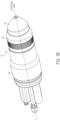
- FIGS. 1a and 1b are exploded and assembled views, respectively, of a liquid-cooled plasma arc torch 10 generally comprising a torch head 102 and a cartridge 104, according to an illustrative embodiment of the invention.
- the cartridge 104 which comprises a plurality of consumable torch components, has a proximal end (region) 14 and a distal end (region) 16 along a central longitudinal axis A of the plasma arc torch 10.
- the torch head 102 includes a torch body 18, a proximal end (region) 20 and a distal end (region) 22 along the longitudinal axis A.
- the torch body 18 can be made of an electrically conductive material, such as brass.
- the proximal end 14 of the cartridge 104 is aligned with and secured to the distal end 22 of the torch head 102 by a retaining cap 120.
- the proximal end 14 of the cartridge 104 matingly engages/connects to the distal end 22 of torch 102.
- the proximal end 14 and the distal end 22 can be connected via at least seven distinct mating joints/junctions/connection points.
- Other engagement means between the torch head 102 and cartridge 104 are possible, including threading, interference fit, snap fit, quick lock, etc.
- a proximal end of a component defines a region of the component along the longitudinal axis A that is away from a workpiece when the torch 10 is used to process the workpiece, and a distal end of the component defines a region of the component that is opposite of the proximal end and close to the workpiece when the troch 10 is used to process the workpiece.
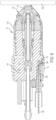
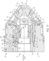
- FIG. 2 is a cross-sectional view of the assembled plasma arc torch 10 of FIG. 1b , according to an illustrative embodiment of the invention.
- an interface 106 in FIG. 1 defines the boundary between the cartridge 104 and the torch head 102 after they are engaged to each other.
- the cartridge 104 which is a substantially unitary element, includes a cartridge tip comprising an electrode 108 (i.e., an arc emitter), a nozzle 110 (i.e., an arc constrictor) and a shield 114 disposed concentrically about the central longitudinal axis A. Components of the cartridge tip can be connected to a cartridge frame 112 of the cartridge 104.
- the cartridge 104 also includes a swirl ring 150 disposed about the longitudinal axis A. Details regarding the cartridge 104 are explained below with reference to FIGS. 15 and 17-25 .
- the torch head 102 includes a torch insulator 118 disposed in the torch body 18 about the longitudinal axis A. Details regarding the torch head 102 are explained below with reference to FIGS. 2-14b .
- the torch insulator 118 of the torch head 102 is substantially disposed in and surrounded by the torch body 18 about the central longitudinal axis A.
- the torch body 18 can be made of an electrically conductive material, such as brass.
- the torch insulator 118 which include a proximal end 21 and a distal end 23, can be made of an electrically insulating material, such as plastic.
- the torch insulator 118, at its proximal end 21, can couple to one or more of a cathode 130, a communication device 122, a pilot arc connection 124 and an ohmic connection 131 while electrically insulating these components from each other and from the torch body 18.
- the torch insulator 118 can include at least one gas opening 126a for coupling to a source of gas (not shown) and introducing the gas to the torch 10.
- the torch insulator 118 can further include at least one coolant opening 128a for coupling to a source of liquid coolant (not shown) and introducing the coolant to the torch 10.
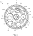
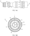
- FIG. 3 is a view of the proximal end 20 of the torch head 102, which shows various electrical, gas and liquid openings at the proximal end 21 of the torch insulator 118, according to an illustrative embodiment of the invention.
- FIG. 4 is a view of the distal end 22 of the torch head 102, which shows various electrical, gas and liquid openings at the distal end 23 of the torch insulator 118, according to an illustrative embodiment of the invention.
- the torch insulator 118 can interconnect a plurality of components that are used to maintain a pilot arc current and/or a transferred arc current between the torch head 102 to the cartridge 104.
- the torch insulator 118 is adapted to connect the cathode 130, a coolant tube 116, the pilot arc connection 124 and a current ring 800 in a configuration that supports both pilot arc current and transferred arc current conduction between the torch head 102 and the cartridge 104.
- the torch insulator 118 includes a main channel 132 (shown in FIG. 2 ) extending from an opening 132a at the proximal end 21 of the torch insulator 118 (shown in FIG. 3 ) to an opening 132b at the distal end 23 of the torch insulator 118 (shown in FIG. 4 ).
- the main channel 132 can be centrally located within the torch insulator 118 such that it is concentric with respect to the central longitudinal axis A.
- the main channel 132 can extend substantially straight within the insulator 118 to connect the openings 132a and 132b.
- the main channel 132 can be configured to house at least a portion of the cathode 130. As shown in FIG.
- the cathode 130 can extend within the main channel 132 along the length of the torch insulator 118.
- a cathode block locking component 250 is used to secure the cathode 130 to the main channel 132 inside of the torch insulator 118.
- FIG. 5 is an exemplary design of the cathode 130 of the torch head 102, according to an illustrative embodiment of the invention.
- the cathode 130 includes a cathode fitting 602 with a distal end coupled to a cathode tube 604, which has a distal end coupled to a cathode block 606.
- Each of the cathode fitting 602, the cathode tube 604 and the cathode block 606 can be made from a conductive material, such as brass or copper.
- the cathode fitting 602 and the cathode block 606 are made of brass, while the cathode tube 604 is made of copper.
- the distal end of the cathode block 606 can electrically and/or physically couple to the coolant tube 116 within the main channel 132 of the torch insulator 118.
- the coolant tube 116 defines an o-ring groove that houses an o-ring 133 to form an interface between an outer surface of the coolant tube 116 and an inner surface of the cathode block 606.
- at least a proximal portion of the coolant tube 116 is inserted within the distal end of the cathode block 606.
- the coolant tube 116 distributes a cooling fluid to the cartridge 104 once the torch head 102 is coupled to the cartridge 104.
- the coolant tube 116 is configured to additionally pass a current from the cathode 130 to the cartridge 104, such as to the electrode 108 of the cartridge 104.
- a cathode block electrode tube 252 (shown in FIG. 2 ), which can be made of a non-conductive material, can be configured to connect with (e.g., threaded into or sealed by interference fit) the cathode block 606 at its proximal end and with the electrode 108 at its distal end.
- the resulting housing which comprises the cathode 130, the cathode block electrode tube 252 and the electrode 108, substantially encases the coolant tube 116 to contain the coolant flow therein.
- FIG. 6 is an exemplary design of the coolant tube 116 of the torch head 102, according to an illustrative embodiment of the invention.
- the coolant tube 116 can be made of a conductive material, such as brass.
- the coolant tube 116 is affixed (e.g., by threading) to the distal end of the cathode block 606 such that it cannot be easily or quickly disconnected.
- the coolant tube 116 is affixed (e.g., by an interference fit) to the distal end of the cathode block 606 such that it can be easily or quickly disconnected.
- the coolant tube 116 can have an electrical connector, such as a Louvertac TM band 702 around an external surface at a proximal end 740, which is the end that is configured to mate with the cathode block 606.
- the Louvertac band 702 is configured to conduct the cutting current carried from the interior surface of the cathode block 606 to the exterior surface of the coolant tube 116 once the proximal end 740 of the coolant tube 116 is inserted into and affixed to the distal end of the cathode block 606.
- the coolant tube 116 can be fixedly secured to the cathode 130 via threads or other current-carrying methods without the Louvertac band 702.
- the coolant tube 116 has an electrical connector, such as a Louvertac TM band 704, around an exterior surface at a distal end 742 of the coolant tube 116, which is the end that is configured to mate with an internal surface of the electrode 108 once the torch head 102 is secured to the cartridge 104.
- the coolant tube 116 includes one or more longitudinal channels 744 on its exterior surface below the Louvertac band 704 at the distal end 742 to limit a pressure drop in the coolant flow between the coolant tube 116 and the electrode 108.
- the coolant tube 116 can be configured to conduct a coolant flow to the electrode 108.
- the coolant tube 116 has an opening 745 at its proximal end 740 and an opening 746 at its distal end 742 for allowing a coolant flow to enter and leave the coolant tube 116, respectively.
- the use of a Louvertac TM band 702 or 704 at one of the distal end 742 or the proximal end 740 or at both ends allows the coolant tube 116 to be slidably coupled to the torch head 102 and likewise allows a cartridge 104 to be slidably coupled to the coolant tube 116. This feature is described below in detail.
- the torch insulator 118 includes a cavity 148 (shown in FIG. 2 ) with an opening 148a at the proximal end 21 of the torch insulator 118 (shown in FIG. 3 ). As shown in FIG. 2 , the cavity 148 can be configured to house the pilot arc connection 124. In some embodiments, the cavity 148 extends partially into the torch insulator 118 along the longitudinal axis A.
- a current ring 800 made of an electrically conductive material (e.g., brass), is located in the distal end 23 of torch insulator 118.
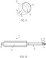
- FIG. 9 is an exemplary design of the current ring 800 of the torch insulator 118 in the torch head 102, according to an illustrative embodiment of the present invention. As shown, the current ring 800 has a ring portion 800a and a protrusion portion 800b. The ring portion 800a has a thin distal rim 802 and the protrusion portion 800b has a distal surface 805.
- an electrically conductive material e.g., brass
- the ring portion 800a of the current ring 800 can be concentrically situated with respect to the coolant tube 116 and the cathode 130 in the torch insulator 118, while the protrusion portion 800b of the current ring 800 can be oriented such that it electrically and/or physically contacts the proximal end of the pilot arc connection 124 housed in the cavity 148.
- the current ring 800 is electrically insulated from the coolant tube 116 and the cathode 130 by a cathode insulator 804 (shown in FIG. 2 ) such that substantially no current is passed between the current ring 800 and the cathode 130 or between the current ring 800 and the coolant tube 116.
- a cathode insulator 804 shown in FIG. 2
- At least a surface of the current ring 800 is exposed from the distal end 23 of the torch insulator 118 via the main electrical channel opening 132b such that a component of the cartridge 104 can physically contact the current ring 800 once the cartridge 104 is attached to the torch head 102.
- both the thin distal rim 802 of the ring portion 800a and the distal surface 805 of the protrusion portion 800b of the current ring 800 can be exposed from the opening 132b.
- FIG. 7 is a sectional view of the plasma arc torch 10 of FIG. 2 oriented to illustrate an exemplary pilot arc current flow path 752 between the torch head 102 and the cartridge 104 of the plasma arc torch 10, according to an illustrative embodiment of the present invention.
- a pilot arc current 752 associated with a highfrequency, high-voltage (HFHV) signal is coupled to a power line from a power supply (not shown) to the plasma arc torch 10.
- the pilot arc current flow 752 can be passed from the power supply to the cathode 130 via the cathode fitting 602.
- the cathode tube 604 that is connected to the cathode fitting 602 then passes the pilot arc current 752 to the cathode block 606, which transfers the current to the coolant tube 116 via the Louvertac band 702 at the proximal end 740 of the coolant tube 116.
- the pilot arc current 752 flows distally through the coolant tube 116 and is transferred to the internal surface of the electrode 108 via the Louvertac band 704 at the distal end 742 of the coolant tube 116, thereby energizing the internal surface of the electrode 108.
- the pilot arc current is passed from the cathode 130 to the electrode 108 without using the coolant tube 116, such as through a physical connection between the cathode 130 and the electrode 108.
- the pilot arc current path 752 induces a spark discharge in a plasma gas flowing in the gap between the electrode 108 and the nozzle 110, thereby generating a pilot arc in the gap.
- the pilot arc current path 752 can return to the torch head 102 by flowing proximally from the nozzle 110, to the swirl ring 150 (which can be made of a conductive material), and to the current ring 800 in the torch head 102.
- the distal end of the swirl ring 150 physically contacts the nozzle 110 at an interface 758.
- the proximal end of the swirl ring 150 physically contacts at least the distal rim 802 of the ring portion 800a of the current ring 800 via a Louvertac electrical connector 756.
- the swirl ring 150 is thus configured to return the pilot arc current 752 from the nozzle 110 of the cartridge 104 to the torch head 102.
- the ring portion 800a of the current ring 800 can transfer the pilot arc current 752 to the protrusion portion 800b of the current ring 800, which passes the pilot arc current flow 752 to to the pilot arc current connection 124 within the cavity 148 to return the pilot arc current to the power supply.
- the gas flow in the gap between the electrode 108 and the nozzle 110 is ionized by the pilot arc so that electrical resistance between the electrode 108 and a workpiece (not shown) becomes small.
- a voltage higher than the voltage used to initiate the pilot arc can be applied across the electrode 108 and the workpiece to induce the arc to transfer to the workpiece after the gap is ionized.
- This arc between the electrode 108 and the workpiece is a transferred arc.
- a transferred arc current which supplies the higher voltage from the power supply, is passed from the cathode 130 to the electrode 108 via the coolant tube 116 and the Louvertac bands 702, 704 in substantially similar fashion as the distal pilot arc current flow 752.
- the transferred arc current is returned from the workpiece to the power supply through separate wirings (not shown).
- the torch insulator 118 can be configured to support wireless communication between the torch head 102 and the cartridge 104.
- the torch insulator 118 includes a cavity 144 (shown in FIG. 2 ) with an opening 144a at the proximal end 21 of the torch insulator 118 (shown in FIG. 3 ).
- the cavity 144 can be configured to retain the communication device 122 within the torch insulator 118.
- the communication device 122 is removable from the cavity 144 via the opening 144a.
- the cavity 144 extends partially into the torch insulator 118 along the central longitudinal axis A such that there is no corresponding opening on the distal end 23 of the torch insulator 118.
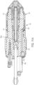
- FIG. 10 is an exemplary design of the communication device 122 of the torch head 102, according to an illustrative embodiment of the present invention.
- the communication device 122 can comprise a radio-frequency identification (RFID) reader adapted to receive RFID signals wirelessly transmitted from a nearby signal device 160 (e.g., an RFID tag) located in the cartridge 104 (shown in FIG. 2 ).
- RFID radio-frequency identification
- the communication device 122 is adapted to process these signals to extract pertinent data transmitted by the signal device 160 about the cartridge 104 (and/or other torch information) and forward the data to a processor (not shown) for analysis.
- the communication device 122 can be placed at a location in the plasma arc torch 10, such as in the torch insulator 118, to minimize the possibility of plasma arc and arc ignition disrupting the wireless communication between the signal device 160 and the communication device 122.
- the communication device 122 can include a connector 806 at its proximal end, an antenna assembly 808 at its distal end, and a processing assembly 810 between the connector 806 and the antenna assembly 808.
- the antenna assembly 808 can include an antenna coil 814 configured to wirelessly transmit RF signals to the signal device 160 to interrogate the signal device 160 and/or receive RF signals from the signal device 160 in response to the interrogation.
- This antenna coil 814 can be located at the distal end of the antenna assembly 808 (i.e., the distal end of the communication device 122) such that when the communication device 122 is inserted into the cavity 144, the antenna coil 814 is embedded at the distal end 23 of the torch insulator 118. Such a placement minimizes wireless communication distance between the antenna coil 814 and the signal device 160 in the cartridge 104 and reduces communication interference between them.
- the antenna coil 814 is positioned at an end face of the distal end of the communication device.
- the antenna coil 814 can be wound around the post 812 at the distal end of the antenna assembly 808.
- the assembly 808 can also include a plastic cylindrical housing configured to feed one or more wires connected to the antenna coil 814 to the processing assembly 810.
- the processing assembly 810 can include a plastic cylindrical housing having one or more hardware components (e.g., a printed circuit board (PCB)) disposed therein.
- PCB printed circuit board
- the PCB which is connected to the wires from the antenna coil 814 of the antenna assembly 808, is configured to (i) power the communication device 122 including the antenna assembly 808, (ii) power the signal device 160, and/or (iii) wirelessly communicate with the signal device 160 via the antenna coil 814 using a communication protocol (e.g., an RFID protocol such as ISO/IEC 15693) to process data from the signal device 160.
- a communication protocol e.g., an RFID protocol such as ISO/IEC 15693
- the PCB can power an entire torch communication circuit on board the torch 10 that includes the communication device 122, the signal device 160 and related components.
- a computing device e.g., a central processing unit or the like
- the circuity that enables wireless communication between the communication device 122 and the signal device 160 is analog while the circuitry that enables (wired or wireless) communication between the communication device 122 and the external computing device is digital.
- placing the communication device 122, including the PCB, in the torch 10 reduces the distance of communication between the communication device 122 and the signal device 160 and therefore reduces noise pickup in the corresponding analog circuitry.
- placing the communication device 122 in the torch 10 can lengthen the communication distance between the communication device 122 and the remote computing device, and therefore can increase noise pickup in the corresponding digital circuitry, but the digital circuitry is more robust (i.e., more immune) to noise pickup than the analog circuitry.
- the communication device 122 is encased in one or more layers of protective material providing, for example, electrical insulation, liquid coolant leakage protection (plus protection from waste carried by the coolant flow), and protection against other environmental factors.
- the housing of the processing assembly 810 and/or the housing of the antenna assembly 808 are made of durable plastic to protect the components therein from liquid and debris.
- the housings can be translucent such that LED signals of the PCB therein can be visible from outside of the housings.
- one or more o-ring seals are used to protect the communication device 122 against liquid damage and create an electrically insulated barrier.
- the communication device 122 in the torch insulator 118 is electrically isolated from the plasma power and ignition circuitry, such as by about 30,000 V of electrical isolation.
- the communication device 122 is configured to fit inside of the torch insulator 118 while accommodating all other components of the torch insulator 118 described above as well the protective layers around the communication device 122, which adds to its bulk.
- the communication device 122 can be designed to be long, thin and/or flexible to better fit within the torch insulator 118.
- the plasma arc torch 100 can cause up to 100 Celsius in ambient temperature, which leaves little margin for operating temperature rise. Therefore, in some embodiments, the communication device 122 is designed to generate minimal operating temperature.
- the communication device 122 can have a low circuit power voltage, a low multi-point-control-unit (MCU) clock frequency, a low operational duty cycle and/or a sleep mode for while not performing to minimize heat generation.
- MCU multi-point-control-unit
- the torch communication circuit which includes the communication device 122 and the signal device 160, is off axis from the central longitudinal axis A of the plasma arc torch 10. This offset allows the communication circuitry to be away from the region of the torch that defines plasma process performance. In general, the area where the communication circuit is placed is not vulnerable to variation in plasma process designs, which allows design freedom for the plasma process and stability for the communication circuitry performance.
- the size of the antenna coil 814 is minimized (e.g., reduced coil diameter) and/or the RFID power is minimized to reduce the size of the resulting RFID field.
- adjacent metal components that can potentially couple with the RFID field can be accounted for and held substantially consistent in size and proximity relative to the torch communication circuit.
- the plasma arc torch 10 does not include a communication system that comprises, for example, the communication device 122 in the torch head 102 or the signal device 106 in the cartridge 104.
- a communication system can be absent in a torch where the cartridge 104 is connected to the torch head 102 or a quick-disconnect torch head, which in turn is connected to a torch receptacle.
- the communication system of the plasma arc torch 10 further includes a second signal device 162 (e.g., an RFID tag) disposed in or on the communication device 122 in the torch insulator 118, such as in the antenna assembly 808 of the communication device 122 close to the antenna coil 814.
- the second signal device 162 can be located in the torch head 102 external to the communication device 122 and/or the torch insulator 118.
- An optional base 164 can be used to hold the second signal device 162 in place.
- the second signal device 162 is configured to read and/or write information about the plasma arc torch 10 (e.g., number of arcs fired) and communicate the information to the plasma cutting system, which can then relay the information to first signal device 160 in the cartridge 104.
- the first and second signal devices 160, 162 can transfer information back and forth between them.
- the torch insulator 118 can be configured to support ohmic contact for the purpose of controlling a relative height between the torch 10 and a workpiece to facilitate torch operation.
- the torch insulator 118 includes an ohmic contact cavity 146 (shown in FIG. 8 ) with an opening 146a at the proximal end 21 of the torch insulator 118 (shown in FIG. 3 ).
- FIG. 8 is a sectional view of the plasma arc torch 10 of FIG. 2 oriented to illustrate an exemplary ohmic contact path 780, according to an illustrative embodiment of the present invention.
- the ohmic contact cavity 146 of the torch insulator 118 in the torch head 102 can be configured to retain an ohmic contact connection 131, which is removable from the cavity 146 via the opening 146a (shown in FIG. 3 ).
- the ohmic contact cavity 146 extends partially into the torch insulator 118 along the longitudinal axis A such that there is no corresponding opening on the distal end 23 of the torch insulator 118.
- the ohmic contact path 780 of FIG. 8 allows a controller (not shown) of the torch 10 to detect and sense a workpiece/plate 782 for the purpose of controlling the relative height between the torch 10 and the workpiece/plate 782 prior to or during a torch operation.
- a controller not shown
- the ohmic contact path 780 when the torch head 102 is mounted during torch operation, an incoming pin (not shown) makes electrical contact with the ohmic contact connection 131 to form the electrical contact path 780.
- the path 780 then continues through the length of the ohmic contact connection 131 to electrically contact the torch body 18 via a set screw 784.
- the path 780 travels distally over the torch body 18 and the retaining cap 120 to reach the shield 114 of the cartridge 104.
- This path 780 allows the controller to sense the location of the workpiece/plate 782 and adjust the relative height accordingly.
- the shield 114 of the cartridge 104 is electrically isolated from the nozzle 110 of the cartridge 104 to allow the ohmic contact path 780 to travel from the torch head 102 to the shield 114 on the outer surface of the torch 10.
- the ohmic contact path 780 of FIG. 8 is electrically isolated from the pilot arc current flow path 752 and/or the transferred arc current flow path by the use of the torch insulator 118.
- pilot arc current flow path 752 and the transferred arc current flow path can be through the torch insulator 118 while the ohmic contact path 780 is mostly through the torch body 18.
- the torch insulator 118 can be configured to direct one or more gas flows from the torch head 102 to the cartridge 104.
- the torch insulator 118 is configured to direct at least one shield gas from the torch head 102 to the cartridge 104.
- Exemplary shield gases include air, oxygen (i.e. O 2 ), and argon.
- the shield gas flow path and channels described herein are also compatible with conducting a shield fluid, such as water, between the torch head 102 and the cartridge 104.
- the torch insulator 118 can include a shield gas channel 850 extending from an opening 126a at the proximal end 21 of the torch insulator 118 (shown in FIG. 3 ) to a shield gas opening 126b at the distal end 23 of the torch insulator 118 (shown in FIG. 4 ).
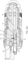
- FIGS. 11a and b are sectional views of the plasma arc torch 10 of FIG. 2 oriented to illustrate an exemplary shield gas flow path 868 from the torch head 102 to the cartridge 104 over the shield gas channel 850 (including shield gas channel segments 850a and 850c), according to an illustrative embodiment of the present invention.
- the shield gas channel 850 can comprise several segments.
- a first channel segment 850a connects the opening 126a on the proximal end 21 of the torch insulator 118 to an internal opening 860 in or on the insulator 118.
- the first channel segment 850a can extend substantially parallel to the longitudinal axis A.
- a second channel segment (not shown) can connect the opening 860 with another internal opening 862 in or on the insulator 118, where the second internal opening 862 is radially offset from the first internal opening 860.
- the internal openings 860, 862 can be radially offset by about 30 degrees to about 90 degrees.
- the second channel segment can extend circumferentially around the torch insulator 118 (or in a different orientation) to connect the internal openings 860, 862.
- a third channel segment 850c connects the internal opening 862 to the opening 126b on the distal end 23 of the torch insulator 118.
- the third channel segment 850c can extend substantially parallel to the longitudinal axis A.
- a corresponding shield gas channel 864 within the cartridge frame 112 of the cartridge 104 fluidly aligns with the shield gas channel segment 850c.
- the shield gas flow 868 can enter the cartridge 104 via a proximal opening 864a of the shield gas channel 864 in the cartridge frame 112.
- the shield gas channel 864 also has an opening 864b at a distal end of the cartridge frame 112 that is fluidly connected to a gas passage 872 between the shield 114 and the nozzle 110.
- the shield gas channel 864 can introduce a shield gas from the torch head 102 to the gas passage 872.
- the cartridge frame 112 includes one or more components in the path of the shield gas channel 864 to adjust one or more parameters (e.g., flow pattern and rate) of the shield gas flow 868 therein. Details regarding the shield gas channel 864, the swirling components of the cartridge frame 112 and the shield gas flow 868 through the cartridge 104 are described below.
- a shield gas is introduced to the torch head 102 via the shield gas opening 126a at the proximal end 21 of the torch insulator 118.
- the gas 868 flows distally through the shield gas channel segment 850a to reach the internal opening 860.
- the gas 868 can then flow circumferentially (or in a different orientation) around the torch insulator 118 via the second segment of the shield gas channel 850 to reach the internal opening 862 that is spaced relative to the internal opening 860.
- the gas 868 flows longitudinally from the opening 862 to the opening 126b on the distal end 23 of the torch insulator 118 via the shield gas channel segment 850c to reach the cartridge 104.
- the shield gas flow 868 Upon exiting the torch head 102 via the opening 126b, the shield gas flow 868 enters the shield gas channel 864 of the cartridge frame 112 in the cartridge 104.
- the gas 868 flows distally through the shield gas channel 864 of the cartridge frame 112 and exits from the opening 864b of the shield gas channel 864 to the gas passage 872 between the shield 114 and the nozzle 110 to cool the two components.
- the shield gas 868 is adapted to exit the cartridge 104 via the shield exit orifice 870.
- the torch insulator 118 of the torch head 102 can direct one or more plasma gases from the torch head 102 to the cartridge 104.
- the torch insulator 118 can be configured to receive multiple sources of gas, select one of the gases or mix the gases, and introduce the selected gas or gas mixture to the cartridge 104.
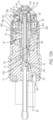
- FIGS. 12a-c are sectional views of the plasma arc torch 10 of FIG. 2 oriented to illustrate an exemplary plasma gas flow path 900 from the torch head 102 to the cartridge 104, according to an illustrative embodiment of the present invention.
- the torch insulator 118 includes two plasma gas openings 200a and 200b at the proximal end 21 of the torch insulator 118, where each opening is configured to receive a plasma gas, such as oxygen (O 2 ), air, nitrogen (N 2 ), hydrogen-based gases (e.g., H35), F5 fuel gas, or a mixture of one or more of these chemicals.
- a plasma gas such as oxygen (O 2 ), air, nitrogen (N 2 ), hydrogen-based gases (e.g., H35), F5 fuel gas, or a mixture of one or more of these chemicals.
- the torch insulator 118 can include a cavity 202 (shown in FIGS. 12a-c ) configured to house a plasma gas valve 204.
- the cavity 202 is connected to an opening 202a at the proximal end 21 of the torch insulator 118 (shown in FIG.
- the plasma gas valve 204 is configured to select one of the gases or mix the gases received from the plasma gas openings 200a and 200b and introduce the resulting gas or gas mixture to the cartridge 104 over a plasma gas channel 206 (shown in FIGS. 12a-c ) and via an opening 200c on the distal end 23 of the torch insulator 118 (also shown in FIG. 4 ).
- the exemplary plasma gas flow path 900 comprises a first plasma gas flow 900a introduced from the plasma gas opening 200a to the plasma gas valve 204 located in the cavity 202 via a connection channel 902.
- the connection channel 902 fluidly connects the opening 200a with an inlet 904 of the plasma gas valve 204 to introduce the first plasma gas flow 902 to the valve 204.
- the plasma gas flow path 900 comprises a second plasma gas flow 900b introduced from the plasma gas opening 200b to the plasma gas valve 204 via a connection channel 906.
- the connection channel 906 fluidly connects the opening 200b with a second inlet 908 for introducing the second plasma gas flow 900b to the plasma gas valve 204.
- FIG. 12a the exemplary plasma gas flow path 900 comprises a first plasma gas flow 900a introduced from the plasma gas opening 200a to the plasma gas valve 204 located in the cavity 202 via a connection channel 902.
- the connection channel 902 fluidly connects the opening 200a with an inlet 904 of the plasma gas valve 204
- the plasma gas valve 204 selects one of the gases or mixes the gases and transmits the resulting plasma gas flow 900c over the plasma gas channel 206 to exit from the opening 200c at the distal end 23 of the torch insulator 118.
- the plasma gas channel 206 is adapted to extend longitudinally along the length of the torch 10 and fluidly connect an outlet 910 of the plasma gas valve 204 to the opening 200c at the distal end 23 of the torch insulator 118.
- the plasma gas flow 900c upon exiting the torch head 102 via the opening 200c, the plasma gas flow 900c enters a corresponding plasma gas channel 912 of the cartridge frame 112 in the cartridge 104 via an opening 912a on a proximal end 15 of the cartridge frame 112.
- the gas 900c flows longitudinally through the plasma gas channel 912 of the cartridge frame 112 and exits from an opening 912b at the distal end 17 of the cartridge frame 112, which introduces the gas to the plasma gas passage 918 between the electrode 108 and the nozzle 110 of the cartridge 104.
- the plasma gas 900c is adapted to flow distally through the passage 918 and exit the cartridge 104 via the central nozzle exit orifice 916 and the central shield exit orifice 870.
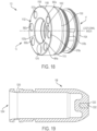
- the swirl ring 150 in the path of the plasma gas flow 900c can introduce a swirling motion to the plasma gas flow 900c. Details regarding the plasma gas channel 912, the swirl ring 150, and the plasma gas flow 900c through the cartridge 104 are described below.
- the shield gas flow 868 and the plasma gas flow 900 are fluidly isolated from each other in both the torch head 102 and the cartridge 104 such that these gases do not cross paths or share the same channels.
- the plasma gas channel 206 and the shield gas channel 850 are fluidly isolated from each other.
- the torch insulator 118 of the torch head 102 is configured to control gas flows through the torch 10 by directing the shield gas flow 868 and the plasma gas flow 900 to the appropriate channels within the cartridge frame 112 for distribution to the appropriate gas passageways in the cartridge 104 (e.g., the passage 872 between the nozzle 110 and the shield 114 for the shield gas flow 868 and the passage 918 between the electrode 108 and the nozzle 110 for the plasma gas flow 900c).
- the torch insulator 118 can be configured to direct a sequence of liquid coolant flow for circulation between the torch head 102 to the cartridge 104.
- Exemplary liquid coolant includes water, propylene glycol, ethylene glycol, or any number of commercially available coolants specially designed for plasma cutting systems.
- the torch insulator 118 can include a coolant opening 128a at the proximal end 21 of the torch insulator 118 for introducing a liquid coolant to the torch head 102.
- FIGS. 13a and b are sectional views of the plasma arc torch 10 of FIG. 2 oriented to illustrate an exemplary liquid coolant flow path 950 that circulates between the torch head 102 and the cartridge 104 in a series of flow segments, according to an illustrative embodiment of the present invention.
- a liquid coolant is first introduced to the torch head 102 via the opening 128a at the proximal end 21 of the torch insulator 118.
- the coolant 950 flows from the opening 128a to the cathode block 606 within the torch insulator 118 over a connection channel 952 and enters the cathode bock 606 via at least one inlet of the cathode block 606.
- FIGS. 14a and b are exemplary profile and proximal views of the cathode block 606 of the torch head 102, respectively, according to an illustrative embodiment of the present invention.
- the cathode block 606 can include a first set of three liquid inlets 620a-c dispersed around an inner circumference of the cathode block 606. In other embodiments, more or fewer inlets are defined.
- the connection channel 952 fluidly connects the torch insulator opening 128a to the first set of liquid inlets 620a-c to conduct the coolant into the cathode block 606.
- the liquid inlets 620a-c of the cathode block 606 can further conduct the liquid coolant into the opening 745 at the proximal end 740 of the coolant tube 116 that can be physically attached to the cathode block 606 as described above.
- the connections between the inlets 620a-c and the opening 745 at the proximal end of the coolant tube 116 are crisscrossed (e.g., for spacing saving purpose) to deliver the coolant from the cathode block 606 to the coolant tube 116.
- the coolant flow path 950 continues on longitudinally toward the distal end 742 of the coolant tube 116.
- the coolant flow 950 exits from the coolant tube 116 via the distal opening 746 of the coolant tube 116 and enters into a cavity 954 defined by the inner surface of the electrode 108 of the cartridge 104, thereby substantially cooling the electrode 108.
- the initial coolant flow path 950 is substantially confined within the main channel 132 of the torch insulator 118 (which receives at least a portion of the cathode 130 and the coolant tube 116) and a corresponding main channel 1020 of the cartridge frame 112 (which connects to the the cavity 954 of the electrode 108).
- the coolant flow 950 reverses direction and continues on proximally in the main channels 1020, 132, along the outer surface of the coolant tube 116. This reverse flow also substantially cools the Louvertac band 704 surrounding an exterior portion of the distal end 742 of the coolant tube 116.
- the coolant flow 950 continues toward the cathode block 606 of the torch head 102.
- the coolant flow 950 can enter the cathode block 606 via the distal opening 622 of the cathode block 606 (shown in FIG. 14a ).
- the coolant 950 flows radially outward over an exit channel 624 of the cathode 130.
- the exist channel 624 fluidly connects the cathode 606 to a first coolant channel 958 of the torch insulator 118 that extends longitudinally along the length of the torch head 102 to again conduct the coolant flow 950 from the torch head 102 into the cartridge 104.
- the first coolant channel 958 fluidly connects the exit channel 624 to a first liquid coolant opening 960a on the distal end 23 of the torch insulator 118 (also shown in FIG. 4 ).
- the first coolant channel 958 conducts the coolant flow 950 from the cathode 130 to the cartridge 104 via the opening 960a of the torch insulator 118 and introduces the coolant flow 950 into an opening 962a on the proximal end 15 of the cartridge frame 112, where the proximal opening 962a is connected to a corresponding first coolant channel 962 of the cartridge frame 112 in the cartridge 104.
- the coolant 950 flows distally through the cartridge frame 112 over the first coolant channel 962 to reach an opening 962b at the distal end 17 of the cartridge frame 112, which fluidly connects the first coolant channel 962 in the cartridge frame 112 to a nozzle opening 966 associated with the nozzle 110.
- the nozzle 110 can be coupled to an outer nozzle component 111 (such as a nozzle jacket for a non-vented nozzle or a nozzle liner for a vented nozzle) and the opening 966 can be on the outer nozzle component 111 such that it can introduce the coolant flow from the distal coolant channel opening 962b to a nozzle coolant flow chamber 965 between an exterior surface the nozzle 110 and an interior surface of the outer nozzle component 111.
- the coolant flow 950 As the coolant flow 950 is conducted distally through the nozzle coolant flow chamber 965 via the nozzle opening 966, it substantially cools the nozzle 110 and the outer nozzle component 111. Upon reaching a distal tip of the nozzle 110, the coolant flow 950 can swirl around at least a portion of a circumference of the nozzle 110 via a circumferential channel (not shown) disposed on the external surface of the nozzle 110. The coolant flow 950 can return proximally on a different side of the nozzle 110 within the flow chamber 965 and toward another opening 967 on the outer nozzle component 111. The second nozzle opening 967 is in turn fluidly connected to a second coolant channel 968 in the cartridge frame 112.
- the second coolant channel 968 interfaces with the second opening 967 of the outer nozzle component 111 at an opening 968b at the distal end 17 of the cartridge frame 112.
- the second coolant channel 968 of the cartridge frame 112 is adapted to conduct the liquid coolant flow 950 away from the nozzle coolant flow chamber 965 and into a corresponding second coolant channel 970 of the torch insulator 118 in the torch head 102 via a a second liquid coolant channel opening 968a on the proximal end 15 of the cartridge frame 112 and a second liquid coolant channel opening 960b at the distal end 23 of the torch insulator 118 (also shown in FIG. 4 ).
- the coolant flow 950 travels proximally through the torch insulator 118 within the second coolant channel 970 of the torch head 102, the coolant flow encounters an internal opening 972 of the second coolant channel 970 in the torch insulator 118. That is, the second coolant channel 970 connects the internal opening 972 with the opening 960b on the distal end 23 of the torch insulator 118.
- the internal opening 972 of the second coolant channel 970 can be fluidly connected to an internal opening 974 of a third coolant channel 976 of the torch insulator 118 via a distribution channel (not shown) extending circumferentially around the torch insulator 118.
- the second coolant channel 970 and the third coolant channel 976 can be radially offset from each other at about 30 degrees to about 90 degrees (e.g., 70 degrees).
- the distribution channel thus connects the internal openings 972, 974 to deliver the coolant flow 950 from the second coolant channel 970 to the third coolant channel 976.
- the coolant 950 flows distally toward a third coolant channel opening 960c on the distal end 23 of the torch insulator 118 (also shown in FIG. 4 ) to again enter the cartridge 104.
- the coolant flow 950 is adapted to enter the cartridge 104 via a corresponding third coolant channel opening 978a on the proximal end 15 of the cartridge frame 112 that is connected to a third coolant channel 978 of the cartridge frame 112 to continue the distal flow toward the shield 114 in the cartridge 104.
- the coolant flow 950 exits the third coolant channel 978 via an opening 978b at the distal end 17 of the cartridge frame 112 to enter a circumferential shield coolant flow region 1222 defined between an outer side surface of the cartridge frame 112 and a corresponding inner surface of the shield 114.
- the coolant flow 950 can travel circumferentially around the shield coolant flow region 1222, thereby cooling the shield 114.
- the coolant flow 950 can return to the cartridge frame 112 on a different side of the flow region 1222 by entering an opening 982b at the distal end 17 of the cartridge frame 112.
- the opening 982b which is in fluid communication with the shield coolant flow region 1222, is connected to a fourth coolant channel 982 of the cartridge frame 112.
- the coolant flow 950 then travels proximally in the fourth coolant channel 982, exits the fourth coolant channel 982 via an opening 982a at the proximal end 15 of the cartridge frame 112, and flows into the torch head 102.
- the coolant flow 950 enters the torch head 102 via a fourth coolant channel opening 960d at the distal end 23 of the torch insulator 118 (also shown in FIG. 4 ).
- the opening 960d at the distal end 23 of the torch insulator 118 is fluidly connected to a fourth coolant channel 984 of the torch insulator 118 configured to deliver the coolant flow 950 from the cartridge 104 to an internal opening 986 in the torch insulator 118, which is fluidly connected to the cathode block 606.
- the cathode block 606 comprises a second set of one or more liquid inlets 626 extending from an exterior surface to an interior surface of the cathode block 606.
- the cathode block 606 includes a second set of three liquid inlets 626a-c dispersed around an outer circumference of the cathode block 606. In other embodiments, more or fewer inlets are defined.
- a connection channel 988 fluidly connects the internal opening 986 of the fourth coolant channel 984 of the torch insulator 118 to the second set of liquid inlets 626a-c to conduct the coolant 950 from the fourth coolant channel 984 into the cathode block 606.
- the connections between the second set of inlets 626a-c and the internal opening 986 are crisscrossed (e.g., for space saving purpose) to deliver the coolant from the fourth coolant channel 984 to the cathode block 606 in a swirling fashion.
- the coolant flow 950 continues on proximally to exit the torch insulator 118 via the cathode tube 604 and the cathode fitting 602 in that order.
- the first coolant channel 958 and the second coolant channel 970 can be radially offset from each other at about 30 degrees to 90 degrees (e.g., about 90 degrees).
- the third coolant channel 976 and the fourth coolant channel 984 can be radially offset from each other at about 30 degrees to 90 degrees (e.g., about 90 degrees).
- the first coolant channel 962 and the second coolant channel 968 can be radially offset from each other by the same degree as the offset between the first coolant channel 958 and the second coolant channel 970 of the torch insulator 118 (e.g., about 90 degrees).
- the third coolant channel 978 and the fourth coolant channel 982 can be radially offset from each other by the same degree as the offset between the third coolant channel 976 and the fourth coolant channel 984 of the torch insulator 118 (e.g., about 90 degrees).
- the second coolant channels 970, 968 are radially offset from the third coolant channels 976, 978 by about 30 degrees to about 90 degrees (e.g., 70 degrees).
- the torch insulator 118 of the torch head 102 in collaboration with the cartridge frame 112 of the cartridge 104, is configured to control distribution of a coolant flow 950 in and out of the the torch head 102 and the cartridge 104 to various components of the cartridge tip, as described above with respect to FIGS. 13 a and b.
- the torch insulator 118 and the cartridge frame 112 can direct the coolant flow 950 in the following sequence: (i) from the cathode 600 to the coolant tube 116 and reverse in the main channel 132 of the torch insulator 118 and the main channel 1020 of the cartridge frame 112 to cool the electrode 108, where each of the main channels 132, 1020 acts as both a supply and return channel; (ii) from the first coolant channel 958 of the torch insulator 118 (i.e.
- the coolant flow 950 comprises only one of the three sets of the supply and return channels to cool one cartridge tip component. In alternative embodiments, the coolant flow 950 comprises two of the three sets of the supply and
- coolant flow path 950 of FIGS. 13a and b is illustrated in a sequence that cools the electrode 108, followed by the nozzle 110, and then the shield 114 of the cartridge tip, other cooling sequences are equally applicable.
- a different sequence can include cooling of the shield 114, followed by the nozzle 110 and then the electrode 108.
- Yet another sequence can include cooling of the nozzle 110, followed by the shield 114 and then the electrode 108.
- any order for cooling these three components of the cartridge tip is contemplated by the present invention.
- the shield gas flow path 868, the plasma gas flow path 900 and the coolant flow path 950 are fluidly isolated from each other in both the torch head 102 and the cartridge 104 such that these fluids do not cross paths nor share the same channels.
- the shield gas flow path 868, the plasma gas flow path 900 and the coolant flow path 950 are predefined based on locking of the torch head 102 with the cartridge 104 in a predetermined orientation. This locking feature will be described below in detail.
- one or more of the coolant channels 968, 970, 976, 984, the plasma gas channel 206 and the shield gas channel 850 are non-concentric with respect to the central longitudinal axis A.
- One or more of the pilot arc connection cavity 148, the communication device cavity 144 and the plasma gas valve cavity 202 are non-concentric with respect to the central longitudinal axis A.
- one or more of the opening 202a for receiving the plasma gas valve 204, the plasma gas openings 200a, 200b, the cavity opening 148a for receiving the pilot arc connection 123, the liquid coolant opening 128a, the cavity opening 146a for receiving the ohmic connection 131, the shield gas opening 126a, the cavity opening 144a for receiving the communication device 122, and the main channel opening 132a are disposed on an end face of the proximal end 21 of the torch insulator 118, where the end face can be substantially planar.
- openings can be disposed non-concentrically on the proximal end face with respect to the central longitudinal axis A.
- the main channel opening 132b are disposed on an end face of the distal end 23 of the torch insulator 118, where the end face can be substantially planar.
- non-concentric means that the applicable channel, cavity or opening is offset relative to the longitudinal axis A.
- each non-concentric channel, cavity or opening is oriented non-symmetrically with respect to the longitudinal axis A.
- the main channel opening 132a at the proximal end 21 of the torch insulator 118, the main channel 132, and the main channel opening 132b at the distal end 23 of the torch insulator 118 are centrally located and disposed concentrically with respect to the central longitudinal axis A.
- the main channel 132 is configured to provide at least one of (i) a pilot arc or transferred arc current or (ii) at least a portion of the liquid coolant flow 950 from the torch head to the cartridge.
- the distal end 23 of the torch insulator 118 can further include a clocking feature 220 (e.g. a pin) configured to secure the torch insulator 118 with the cartridge frame 112 in a predetermined radial orientation upon engagement between the torch head 102 and cartridge 104.
- FIG. 15 is a view of the proximal end 15 of the cartridge frame 112, according to an illustrative embodiment of the present invention.
- the proximal end 15 of the cartridge frame 112 can include a clocking feature (e.g., a pin cavity) 1002 that can interact with the corresponding clocking feature 220 on the distal end 23 of the torch insulator 118 to form at least a section of the interface 106 (shown in FIG.
- the end face of the distal end 23 of the torch insulator 118 is substantially planar.
- the end face of the proximal end 15 of the cartridge frame 112 can also be substantially planar such that the interface 106 between them is substantially planar.
- the first liquid coolant channel opening 960a on the distal end 23 of the torch insulator 118 is aligned with the first coolant channel opening 962a at the proximal end 15 of the cartridge frame 112 (shown in FIGS. 13a and 15 ) to fluidly connect the first liquid coolant channel 958 of the torch insulator 118 with the first liquid coolant channel 962 of the cartridge frame 112 (shown in FIG. 13a ).
- the second liquid coolant channel opening 960b of the torch insulator 118 (shown in FIGS. 4 and 13a ) is aligned with the second coolant channel opening 968a at the proximal end 15 of the cartridge frame 112 (shown in FIGS. 13a and 15 ) to fluidly connect the second coolant channel 970 of the torch insulator 118 with the second coolant channel 968 of the cartridge frame 112 (shown in FIG. 13a ).
- the third liquid coolant channel opening 960c of the torch insulator 118 (shown in FIGS.
- the fourth liquid coolant channel opening 960d of the torch insulator 118 (shown in FIGS. 4 and 13b ) is aligned with the fourth coolant channel opening 982a of the cartridge frame 112 (shown in FIGS. 13b and 15 ) to fluidly connect the fourth coolant channel 984 of the coolant insulator 118 with the fourth coolant channel 982 of the cartridge frame 112 (shown in FIG. 13b ).
- the shield gas opening 126b on the distal end 23 of the torch insulator 118 (shown in FIGS. 4 and 11b ) is aligned with the shield gas opening 864a at the proximal end 15 of the cartridge frame 112 (shown in FIGS. 11b and 15 ) to fluidly connect the third shield gas channel segment 850c of the torch insulator 118 with the shield gas channel 864 of the cartridge frame 112 (shown in FIG. 11b ).
- the plasma gas opening 200c on the distal end 23 of the torch insulator 118 (shown in FIGS.
- the reader device 122 is rotationally aligned with the signal device 160.
- the antenna coil 814 embedded in the torch insulator 118 can map to an area 230 at the distal end 23 of the torch insulator 118 (shown in FIG. 4 ) with a center 232 that substantially aligns with a center 1018 of an area 1016 at the proximal end 15 of the cartridge frame 112 (shown in FIG. 15 ), which maps to the signal device 160 embedded in the cartridge 104.
- Such rotational alignment between the centers 232, 1018 reduces communication interference between the reader device 122 and the signal device 160.
- FIG. 31 is a portion of the plasma arc torch 10 of FIG. 2 illustrating exemplary locations of the communication device 122 and the signal device 160 once the torch head 102 and the cartridge 104 are in the predetermined radial orientation relative to each other, according to an illustrative embodiment of the present invention.
- a distance 816 between the longitudinal and radial center of the antenna coil 814 and the longitudinal and radial center of the signal device 160 is less than a distance between the longitudinal and radial center of the signal device 160 and any adjacent metallic material disposed in the torch head 102 or the cartridge 104.
- the RFID field generated by the antenna coil 814 is toroidal in shape around the perimeter of the disc-shaped RFID tag 160.
- a cross section of the toroidal field at any point is a circle.
- the distance between the RFID tag 160 and the reader device 122 along an x axis is smaller or closer than the distance between the RFID tag 160 to any adjacent metal along the Y axis.
- the field is configured such that it does not encounter any metal before it encounters the RFID tag 160.
- the signal device 160 and the reader device 122 are oriented such that a straight-line axis extends through a centerline of the signal device 160 and a centerline of the reader device 122.
- the antenna coil 814 of the reader device 122 is oriented substantially parallel to the signal device 160.
- the antenna coil 814 and the RFID tag 160 communicate at a frequency of about 13.5 MHz.
- the distal opening 132b of the main channel 132 of the torch insulator 118 is adapted to align with the opening 1020a at the proximal end 15 of the cartridge frame 112 to connect to the main channel 1020 of the cartridge frame 112.
- the distal end 742 of the coolant tube 116 is adapted to be inserted into the main channel 1020 of the cartridge frame 112 via the opening 1020a.
- An opening 1020b of the main channel 1020 at the distal end 17 of the cartridge frame 112 is connected to the cavity 954 of the electrode 108 such that the coolant tube 116 extends through the opening 1020b and into the cavity 954.
- pilot arc current and/or transferred arc current from the power supply can be routed from the cathode 130 of the torch head 102 to the coolant tube 116, both of which are affixed to the torch insulator 118, and to the electrode 108 of the cartridge 104 via the inner surface of the electrode cavity 954.
- the current-carrying coolant tube 116 thus energizes the interior surface of the electrode 108.
- one or more Louvertac bands 702, 704 on either or both ends 740, 742 of the coolant tube 116 are used to facilitate conduction of electricity from the power supply to the inner surface of the electrode 108.
- the use of at least the Louvertac band 704 at the distal end 742 of the coolant tube 116 radially aligns/centers the electrode 108 relative to the coolant tube 116, but does not affix the electrode 108 to any particular radial orientation.
- an operator can apply an axial force to push the electrode 108 proximally against the coolant tube 116 until the Louvertac band 704 at the distal end 742 of the coolant tube 116 is fully seated within the cavity 954 of the electrode 108 and is covered by most of the cavity 954.
- the Louvertac band 704 of the coolant tube 116 thus allows the electrode 108 to be axially pushed on or pulled off during engagement or disengagement, respectively, without the use of threading (or other clocking movement), thereby enabling the use of a tool-free and/or threadless electrode 108.
- the simple push-on/pull-off feature is also compatible with the engagement between the clocking feature 220 of the torch insulator 118 and the clocking feature 1002 of the cartridge frame 112 to form the interface 106. That is, the coupling between the torch head 102 and the cartridge 104 can be governed by the locking features 220, 1002 without the need to account for any threading or other clocking requirement between the electrode 108 and the coolant tube 116.
- allowing the coolant tube 116 and the Louvertac band 704 to carry the pilot arc/ transferred arc current to the cartridge 104 separates (i) the physical interface between the torch insulator 118 and the cartridge frame 112 from (ii) the electrical connection between the cathode 130/coolant tube 116 and the electrode 108.
- This separation is adapted to maximize design space and simplify torch assembly.
- the relatively straight axial installation and removal of the coolant tube 116 (and thus the torch head 102) from the electrode 108 (and thus the cartridge 104) promotes quicker consumable replacement and installation.
- the Louvertac band 704 can be easily inspected and readily serviced.
- other current-carrying and/or retaining features can be used, such as thread attachments, interference fits, etc.
- the electrode 108 does not need to be in directly electrical or physical contact with the torch head 102 for current transfer purposes.
- the electrode 108 is electrically isolated from the torch head 102 by the cathode block electrode tube 252, which connects the electrode 108 to the cathode 130 and the coolant tube 116.
- the cathode block electrode tube 252 can be made of a non-conductive material such as plastic.
- the electrode 108 is shorter than an electrode that is used to receive a current directly from the cathode. In this case, because the electrode 108 no longer physically or electrically contacts the cathode 130, the electrode 108 can be shorter, such as more than 25% shorter, than a direct-contact electrode.
- FIG. 16 is a sectional view of an exemplary design of the retaining cap 120 of FIG.
- the retaining cap 120 includes a body 764, a proximal end 760 and a distal end 762 extending along the longitudinal axis A.
- the proximal end 760 of the retaining cap body 764 includes an engagement feature 766 (e.g., groove, thread or step) circumferentially disposed on an internal surface to capture the torch head 102 against the retaining cap body 764.
- the distal end 762 of the retaining cap body 764 includes an engagement feature 768 (e.g., groove, thread or step) disposed on an internal surface to capture the cartridge 104 against the retaining cap body 764.
- the retaining cap 120 can securely and circumferentially surround an external surface of the torch head 102 at the distal end 22 of the torch head 102 and an external surface of the cartridge 104 at the proximal end 14 of the cartridge 104.
- the torch head 102 and/or the cartridge do not rotate with respect to the retaining cap 120.
- an operator can slide the retaining cap 120 over the cartridge 104 and/or the torch head 102 to lock the parts without using any rotational movement.
- the retaining cap 120 is provided as a part of the torch head 102.
- the retaining cap 120 is provided as a part of the cartridge 104.
- the retaining cap 120 is provided as a distinct component separate from the cartridge 104 or torch head 102.
- FIG. 17 is a sectional view of the cartridge 104 of FIG. 1 , where the cartridge 104 is a non-vented cartridge, according to an illustrative embodiment of the present invention.
- the cartridge 104 can generally include the cartridge frame 112 coupled to the cartridge tip that includes the electrode 108, the nozzle 110, which is a non-vented nozzle attached to a nozzle jacket 111, and the shield 114.
- the cartridge frame 112 is adapted to form an interface between the cartridge tip and the torch head 102, thereby connecting the cartridge tip to the torch head 102.
- the various components of the cartridge 104 can be concentrically disposed about the longitudinal axis A of the plasma arc torch 10.
- the cartridge 104 includes multiple retaining features that allow the components of the cartridge tip to align with and engage to one or more channels in the cartridge frame 112 such that these channels can conduct liquid and gas from the torch head 102, through the cartridge frame 112, and to the desired components in the cartridge tip.
- the proximal end 14 of the cartridge 104 is substantially planar.
- the various components of the cartridge tip can be secured, either directly or indirectly, to the cartridge frame 112 while achieving axial alignment and radial alignment (i.e., centering) with respect to the cartridge frame 112.
- the electrode 108 can be secured to the cartridge frame 112 with at least a portion of the electrode 108 disposed in the central channel 1020 of the cartridge frame 112.
- the electrode 108 is secured to the cartridge frame 112 via the swirl ring 150 that surrounds at least a portion of the main channel 1020.
- an outer diameter of the electrode 108 can be secured to an inner diameter of the swirl ring 150 such that at least a proximal portion of the electrode 108 is inserted into a distal portion of the swirl ring 150.
- the swirl ring 150 can be secured to the electrode 108 via the electrode insulator 754.
- the electrode 108 includes an outer retaining feature 1066 (e.g., one or more steps of varying diameter of the electrode 108) on an exterior surface configured to matingly engage an inner retaining feature 1068 (e.g., one or more complementary steps or protrusions) on an interior surface of the electrode insulator 754 to prevent axial movement of the electrode 108 and the electrode insulator 754 relative to each other.
- the mating between the retaining features 1066, 1068 can be one of snap fit, press fit or interference fit.
- the electrode insulator 754 includes an outer retaining feature 1056 (e.g., a step of varying diameter of the electrode insulator 754) on an exterior surface to matingly engage an inner retaining feature 1054 (e.g., a complementary step or protrusion) on an interior surface of the swirl ring 150 to prevent axial movement of the electrode insulator 754 and the swirl ring 150 relative to each other.
- the mating between the retaining feature 1054, 1056 can be one of snap fit, press fit or interference fit.
- the resulting interface 1055 between the electrode insulator 754 and the swirl ring 150 also radially aligns/centers the two components. If the swirl ring 150 is substantially non-conductive, the swirl ring 150 can be directly secured to the electrode 108 without the use of the electrode insulator 754. In some embodiments, an outer diameter of the swirl ring 150 is matingly engaged to an inner diameter of the cartridge frame 112 to couple the electrode 108 to the cartridge frame 112.
- the swirl ring 150 can be secured to the cartridge frame 112 by matingly engaging an outer retaining feature 1052 (e.g., a step of varying diameter of the swirl ring 150) on an exterior surface with an inner retaining feature 1058 (e.g., a complementary step or protrusion) on an interior surface of the cartridge frame 112 to prevent axial movement of the swirl ring 150 and the cartridge frame 112 relative to each other.
- the mating between the retaining features 1052, 1058 can be one of snap fit, press fit or interference fit.
- the resulting interface 1053 between the the swirl ring 150 and the cartridge frame 112 also radially aligns/centers the two components.
- the nozzle 110 and the nozzle jacket 111 can be engaged between the swirl ring 150 and the cartridge frame 112.
- an outer diameter of the swirl ring 150 is engaged to an inner diameter of the nozzle 110.
- the swirl ring 150 can be secured to the nozzle 110 by matingly engaging an outer retaining feature 1050 (e.g., one or more steps of varying diameter of the swirl ring 150) on an exterior surface with an inner retaining feature 1060 (e.g., a complementary step or protrusion) on an interior surface of the nozzle 110 to prevent axial movement of the swirl ring 150 and the nozzle 110 relative to each other.
- the mating between the retaining features 1050, 1060 can be one of snap fit, press fit or interference fit.
- the resulting interface 1051 between the the swirl ring 150 and the nozzle 110 also radially aligns/centers the two components.
- An outer diameter of the nozzle 110 is secured to an inner diameter of the cartridge frame 112.
- the nozzle 110 can be secured to the cartridge frame 112 by matingly engaging at least one outer retaining feature 1070 (e.g., one or more steps of varying diameter of the nozzle 110) on an exterior surface to at least one inner retaining feature 1072 (one or more complementary steps or protrusions) on an interior surface of the cartridge frame 112 to prevent axial movement of the nozzle 110 and the cartridge frame 112 relative to each other.
- the mating between the retaining features 1070, 1072 can be one of snap fit, press fit or interference fit.
- the resulting interface 1071 between the nozzle 110 and the cartridge frame 112 also radially aligns/centers the two components.
- the shield 114 can be coupled to an outer surface the cartridge frame 112.
- an outer diameter of the cartridge frame 112 is secured to an inner diameter of the shield 114 by matingly engaging an outer retaining feature 1062 (e.g., a step of varying diameter of the cartridge frame 112) on an exterior surface of the cartridge frame 112 with an inner retaining feature 1064 (e.g., a complementary step or protrusion) on an interior surface of the shield 114 to prevent axial movement of the cartridge frame 112 and the shield 114 relative to each other.
- the mating between the retaining features 1062, 1064 can be one of snap fit, press fit or interference fit.
- the resulting interface 1063 between the cartridge frame 112 and the shield 114 also radially aligns/centers the two components.
- the cartridge frame 112 can include an indentation 1065 on an exterior surface configured to receive a distal portion of the shield 114 via crimping, thereby further securing and aligning the shield 114 to the cartridge frame 112.
- the retaining features 1050-1072 described above can mate with their corresponding retaining features through one of snap fit, press fit, interference fit, crimping, frictional fitting, gluing, cementing or welding.
- the retaining features 1050-1072 include one or more sealing o-rings or gaskets, made of hardening epoxy or rubber for example.
- the retaining features 1050-1072 allow the nozzle 110, the jacket 111, the shield 114 and/or the electrode 108 of the cartridge tip to align with and engage to one or more channels in the cartridge frame 112 such that these channels can conduct liquid and/or gas from the torch head 102, through the cartridge frame 112, and to the desired components in the cartridge tip.
- the liquid and gas connections between the cartridge frame 112 and the cartridge tip is described below in detail.
- FIG. 18 is an exemplary design of the cartridge frame 112 of the cartridge 104 of FIG. 17 , according to an illustrative embodiment of the present invention.
- the cartridge frame 112 includes a generally cylindrical insulator body 1100 disposed between the torch head 102 and the cartridge tip. More specifically, the insulator body 1100 includes an inner region 1106, an outer side surface 1108, an inner side surface 1110 surrounding and forming the main channel 1020, the proximal end 15 having an end face 1102, and the distal end 17 having an end face 1104.
- the proximal end 15 of the cartridge frame 112 which is described above with respect to FIG.
- the central opening 1020a for receiving an electrical current and/or the coolant flow 950 from a coolant tube 116 of the torch head 102, a plasma gas opening 912a for receiving the plasma gas flow 900c from the torch insulator 118, a shield gas opening 864a for receiving the shield gas flow 868 from the torch insulator 118 and four liquid coolant openings 968a, 978a, 962a and 982a for conducting the liquid coolant flow 950 in and out of the cartridge 104.
- these openings are disposed on the end face 1102 of the proximal end 15 of the insulator body 1100.
- the end face 1102 is substantially coplanar with the proximal end 14 of the cartridge 104.
- these openings are configured to be in electrical and/or fluid communication with their corresponding openings on the distal end 23 of the torch insulator 118 once the torch head 102 is aligned with and connected to the cartridge 104 in a predetermined orientation via the locking feature 1002 of the cartridge frame 112 and the corresponding locking feature 220 of the torch insulator 118.
- the electrode 108 is aligned with and connected to the main channel 1020 disposed in the insulator body 1100 of the cartridge frame 112.
- the channel 1020 can be centrally disposed in the insulator body 110 with the central longitudinal axis A extending therethrough to connect the opening 1020a on the end face 1102 of the proximal end 15 of the cartridge frame 112 to the opening 1020b on the end face 1104 of the distal end 17 of the cartridge frame 112.
- the distal opening 1020b is in turn connected to and aligned with the cavity 954 of the electrode 108 (shown in FIG. 2 ).
- Such an electrode interface allows the coolant tube 116 to be inserted into the main channel 1020 to pass an electrical current (i.e., a pilot arc or transferred arc current) from the cathode 130 of the torch head 102 to the inner surface of the electrode 108, as described above.
- an electrical current i.e., a pilot arc or transferred arc current
- the electrode 108 can be electrically isolated from the cathode 130, as described above.
- the electrode 108 is electrically connected to the cathode 130 to receive a current directly from the cathode 130.
- the same electrode interface i.e., between the electrode 108 and the torch head 102 via the main channel 1020 of the cartridge frame 112 can allow the torch head 102 to introduce a liquid coolant to the electrode 118 from inside of the coolant tube 116.
- This liquid coolant conduction feature of the main channel 1020 of the cartridge frame 112 is explained in detail below.
- FIG. 19 is an exemplary design of the electrode 108 of the cartridge 104 of FIG. 17 , according to an illustrative embodiment of the present invention.
- An emissive insert 1200 can be disposed in the distal end 1202 of the electrode 108 so that an emission surface is exposed.
- the insert 1200 can be made of hafnium or other materials that possess suitable physical characteristics, including corrosion resistance and a high thermionic emissivity. Forging, impact extrusion, or cold forming can be used to initially form the electrode 108 prior to finish machining the component.
- the proximal end 1204 of the electrode 108 can be disposed in and aligned with the main channel 1020 of the cartridge frame 112 via the distal opening 1020b of the cartridge frame 112.
- the electrode 108 can be connected to the cartridge frame 112 using at least the swirl ring 150 and the electrode insulator 754. In some embodiments, the electrode 108 does not include any threads for connection to the electrode insulator 754 or the swirl ring 150. As explained above, such a connection can be made through one of press fit, interference fit, crimping or snap fit. In some embodiments, the electrode 108 is shorter than an electrode that is used to receive an electrical current directly from the cathode 130 (i.e., without using the coolant tube 116). In these cases, because the electrode 108 does not need to physically or electrically contact the cathode 130, the electrode 108 can be shorter, such as more than 25% shorter, than a direct-contact electrode.
- the electrode 108 includes an o-ring groove 1205 at the proximal end 1204, where the o-ring groove 1205 is configured to house an o-ring that can be used to seal a plasma chamber/plenum 109 cooperatively defined by the electrode 108 and the nozzle 110. Such sealing prevents the plasma gas flow 900c from traveling between the electrode 108 and the electrode insulator 754 (shown in FIG. 17 )..
- the shield gas passage 872 formed between the shield 114 and the nozzle jacket 111 is aligned with the shield gas channel 864 disposed in the insulator body 1100 of the cartridge frame 112 (shown in FIGS. 11a and b ).
- the shield gas channel 864 (shown in FIGS. 11a and b ) can extend substantially parallel to the longitudinal axis A in the inner region 1106 of the insulator body 1100, but offset from the central longitudinal axis A (i.e., non-concentric with respect to the longitudinal axis A).
- the shield gas channel 864 connects the opening 864a on the end face 1102 at the proximal end 15 of the cartridge frame 112 to the opening 864b at the distal end 17 of the cartridge frame 112.
- the opening 864b is disposed on the end face 1104 of the distal end 17 of the cartridge frame 112.
- the opening 864b of the shield gas channel 864 which is distal to the opening 864a along the longitudinal axis A, is disposed on the outer side surface 1108 or the inner side surface 1110 of the cartridge frame body 1100 (i.e., the channel 864 does not extend through the entire length of the body 1100 in the longitudinal direction).
- the opening 864b is in turn fluidly connected to the shield gas passage 872, which allows the shield gas flow 868 to pass from the torch head 102, through the cartridge frame 112 of the cartridge 104, and into the shield gas passage 872 (shown in FIGS. 11a and b ).
- the shield gas channel 864 can be configured to provide a metering function to the shield gas flow 868 therein.
- the diameter of the shield gas channel 864 can vary over the length of the channel to provide the metering function.
- the diameter of the shield gas channel 864 at the distal end 17 of the cartridge frame 112 can be about half of the diameter of the shield gas channel 864 at the proximal end 15 of the cartridge frame 112 to reduce the flow rate of the shield gas flow 868.
- the cartridge frame 112 includes one more components in the path of the shield gas channel 864 to adjust one or more properties of the shield gas flow 868 therein.
- the cartridge frame 112 can include an adjustment component, such as a two-piece component comprising a baffle 1112 and a shield swirl ring 1114.
- the baffle 1112 and the shield swirl ring 1114 are circumferentially disposed within the insulator body 1100 of the cartridge frame 112 at its distal end 17 and the two components are in the path of the shield gas channel opening 864b such that they adjust certain flow parameters and introduce a swirling motion to the shield gas flow 868 as it exits the cartridge frame 112 and into the shield gas passage 872.
- the use of these two separate components 1112, 1114 provide manufacturing and assembly advantages as an operator can use different combinations of baffles and shield swirl rings to develop different types of shield gas flows.
- FIG. 20 is a cross-sectional view of the baffle 1112 and the shield swirl ring 1114 attached to the cartridge frame 112 of the cartridge 104 of FIG. 17 , according to an illustrative embodiment of the present invention.
- at least one of the baffle 1112 or the shield swirl ring 1114 is made of a non-conductive material, such as Torlon TM .
- at least one of the baffle 1112 or the shield swirl ring 1114 is made of a conductive material.
- the baffle 1112 and the shield swirl ring 1114 can be individually manufactured through molding, stamping or die casting.
- the baffle 1112 is situated proximal to the shield swirl ring 1114 such that when the shield gas flow 868 travels distally, it is first regulated by the baffle 1112 and then by the shield swirl ring 1114. In other embodiments, the position of the baffle 1112 and the shield swirl ring 1114 are reversed.
- the baffle 1112 can be circumferentially disposed within the insulator body 1100 of the cartridge frame 112, such as within a cavity 1116 at the distal end 17 of the insulator body 1100.
- the baffle 1112 can be secured to the cavity 1116 by one of interference fit or press fit.
- the baffle 1112 includes a longitudinal portion 1118 and and a radial portion 1120 that is connected to the longitudinal portion 1118 at an angle such that the radial portion 1120 covers a portion of the width 1122 of the cavity 1116, but leaves a radial clearance 1124 between an outer diameter of the radial portion 1120 and an inner surface of the cavity 1116.
- the shield gas flow 868 within the shield gas channel 864 is adapted to be dispersed by the baffle 1112 to flow evenly around its outer diameter through the radial clearance 1124 and into the swirl ring 1114.
- the radial clearance 1124 is shaped and dimensioned to adjust at least one parameter of the shield gas flow 868.
- the radial clearance 1124 can adjust a flow rate and/or fluid pressure of the shield gas flow 868.
- increasing the size of the radial clearance 1124 increases the flow rate of the shield gas flow 868, in which case the plasma arc torch system can adjust accordingly to maintain a constant pressure.
- increasing the size of the radial clearance 1124 decreases the gas pressure, in which case the plasma arc torch system can adjust accordingly to maintain a constant flow rate.
- FIG. 21 is a cross-sectional view of the shield swirl ring 1114, according to an illustrative embodiment of the present invention.
- the shield swirl ring 1114 can define a first set of ports 1126 around a first circumference of the swirl ring 1114 and a second set of ports 1128 around a second circumference of the swirl ring 1114, where each port connects an interior surface of the cartridge frame 112 to an exterior surface of the cartridge frame 112.
- the first set of ports 1126 are offset from their respective ones of the second set of ports 1128.
- the combination of the baffle 1112 and the shield swirl ring 1114 can adjust parameters of the shield gas flow 868 as it travels distally through the shield gas channel 864 to the shield gas passage 872.
- the shield gas flow 868 in the plasma arc torch 10 is configurable by varying the size of the clearance 1124 of the baffle and/or the sizes of the first and second sets of ports 1126, 1128 in the shield swirl ring 1114.
- the plasma gas passage 918 formed between the electrode 108 and the nozzle 110 is aligned with the plasma gas channel 912 disposed in the insulator body 1100 of the cartridge frame 112 (shown in FIGS. 12a-c ).
- the plasma gas channel 912 (shown in FIGS. 12a-c ) can extend substantially parallel to the longitudinal axis A in the inner region 1106 of the insulator body 1100, but offset from the longitudinal axis A (i.e., non-concentric with respect to the longitudinal axis A).
- the plasma gas channel 912 connects the opening 912a on the proximal surface 1102 at the proximal end 15 of the cartridge frame 112 to the opening 912b.
- the opening 912b of the plasma gas channel 912 which is distal to the opening 912a along the longitudinal axis A, is disposed on the inner side surface 1110 of the cartridge frame body 1100 and in fluid communication with the central channel 1020.
- the plasma gas channel 912 does not extend over the entire length of the cartridge frame body 1100 in the longitudinal direction.
- FIG. 22 is a perspective view of the cartridge frame 112 illustrating various channel openings, including the opening 912b of the plasma gas channel 912, according to an illustrative embodiment of the present invention.
- the opening 912b is on the inner side surface 1110 in a central region of the cartridge frame 112, and the opening 912b is fluidly connected to the central channel 1020.
- the plasma gas channel 912 extends over the entire length of the cartridge frame 112 with the opening 912b located on the distal end face 1104 of the cartridge frame insulator body 1100.
- the opening 912b is fluidly connected to the plasma gas passage 918.
- Such a connection allows the plasma gas flow 900c to pass from the torch head 102, through the cartridge frame 112, and into the plasma gas passage 918, which merges into the central main channel 1020, before the plasma gas flow 900c exits the torch 10 via the central nozzle exit orifice 916 and the central shield exit orifice 870 (shown in FIGS. 12a-c ).
- the cartridge frame 112 includes one more components in the path of the plasma gas channel 912 configured to adjust one or more properties of the plasma gas flow 900c therein.
- the cartridge frame 112 can include the swirl ring 150 circumferentially situated between the electrode insulator 754 and the nozzle 110 around the main channel 1020.
- the swirl ring 150 can be aligned with the distal plasma gas channel opening 912b such that the swirl ring 150 can introduce a swirling motion to the plasma gas flow 900c as it exits the plasma gas channel 912 via the opening 912b on the inner side surface 1110 of the cartridge frame 112 and into the plasma gas passage 918.
- FIG. 23 is an exemplary design of the swirl ring 150 of the cartridge 104 of FIG. 17 , according to an illustrative embodiment of the present invention.
- the swirl ring 150 can be defined by a substantially hollow, elongated body 1170 having a proximal end 1174 and a distal end 1172 along the central longitudinal axis A of the plasma arc torch 10.
- the hollow body 1170 of the swirl ring 102 at the distal end 1172 is dimensioned to receive a least a portion of the electrode 104 either directly or indirectly via the electrode insulator 754.
- the swirl ring 150 includes a set of radially spaced gas flow openings 1176 disposed about the distal end 1172 of the elongated body 1170, such as around a circumference of its distal end 1172.
- Each gas flow opening 1176 can extend from an interior surface to an exterior surface of the elongated body 1170 and is oriented to impart a tangential velocity component to the plasma gas flow 900c traveling in the gas passage 918 between the electrode 108 and the nozzle 110, thereby causing the gas flow 900c to swirl.
- This swirl creates a vortex that constricts the plasma arc and stabilizes the position of the arc on the insert 1200 of the electrode 108.
- a component of the cartridge tip (e.g., the electrode 108, the nozzle 110 or the shield 114) can be aligned with at least one cooling channel (e.g., channel 1002, 962 or 978) and at least one coolant return channel (channel 1002, 968 or 982) in the insulator body 1100 of the cartridge frame 112 to receive a liquid coolant flow from the torch head 102 and return at least a portion of the fluid flow to the torch head 102, respectively.
- Each of the cooling channels and the return channels with the exception of the main channel 1002, can be non-concentric with respect to the central longitudinal axis A and asymmetric about the longitudinal axis A.
- none of the cooling and returning channels are overlapping. That is, with the exception of the main channel 1002, each of the cooling and returning channels is either a liquid inlet channel or a liquid outlet channel.
- the central channel 1020 extends through the insulator body 1100 of the cartridge frame 112 to connect its opening 1020a on the end face 1102 at the proximal end 15 of the cartridge frame 112 to its opening 1020b at the distal end 17 of the cartridge frame 112.
- the proximal opening 1020a is aligned with and connected to the main channel opening 132b of the torch insulator 118.
- the distal opening 1020b is aligned with and connected to the cavity 954 of the electrode 108, which allows the coolant flow 950 to pass from the torch head 102, through the cartridge frame 112 while inside of the coolant tube 116, and into the cavity 954 of the electrode 108 (shown in FIGS. 13a and b ).
- This connection also allows the coolant flow 950 to impinge on the inner surface of the distal end of the cavity 954 such that the coolant flow 950 can reverse direction and travel proximally through the main channel 1020 along an outer surface of the coolant tube 116 toward the torch head 102 (shown in FIGS. 13a and b).
- This reverse coolant flow over the exterior surface of the coolant tube 116 also substantially cools the Louvertac band 704 attached to the distal end 742 of the coolant tube 116.
- the reverse coolant flow can travel through the longitudinal channels 744 on the exterior surface of the coolant tube 116 beneath the Louvertac band 704, thereby limiting a pressure drop between the coolant tube 116 and the electrode 108.
- the nozzle opening 966 which can be formed on the nozzle jacket 111, is aligned with the first coolant channel 962 disposed in the insulator body 1100 of the cartridge frame 112 (shown in FIGS. 13a and b).
- the nozzle opening 966 allows the coolant flow 950 from the first coolant channel 962 to enter the nozzle coolant flow chamber 965 between an exterior surface of the nozzle 110 and an interior surface of the nozzle jacket 111.
- the first coolant channel 962 (shown in FIGS.
- the first coolant channel 962 can connect the opening 962a on the end face 1102 at the proximal end 15 of the cartridge frame 112 to the opening 962b of the cartridge frame 112, which is distal to the opening 962a along the longitudinal axis A.
- the opening 962b is in turn fluidly connected to the nozzle opening 966, which allows the coolant flow 950 to travel distally from the torch head 102, through the cartridge frame 112 of the cartridge 104, and into the nozzle coolant flow chamber 965 (shown in FIGS. 13a and b ).
- the opening 962b of the first coolant channel 962 is disposed on the inner side surface 1110 of the cartridge frame body 1100 and in fluid communication with the central channel 1020.
- the first coolant channel 962 does not extend over the entire length of the cartridge frame body 1100 in the longitudinal direction.
- the opening 962b of the first coolant channel 962 is illustrated in FIG. 22 . As shown, the opening 962b is on the inner side surface 1110 toward the distal end 17 of the cartridge frame 112, and the opening 962b is fluidly connected to the central channel 1020.
- the first coolant channel 962 extends over the entire length of the cartridge frame 112 with the opening 962b located on the distal end face 1104 of the cartridge frame insulator body 1100.
- the opening 962b is fluidly connected to the nozzle opening 966 in the nozzle jacket 111.
- Such a connection allows the liquid coolant flow 950 to pass from the torch head 102, through the cartridge frame 112, and into the nozzle coolant flow chamber 965 between the nozzle 110 and the nozzle jacket 111 to cool the two nozzle components.
- the nozzle opening 966 is configured to be aligned with the first coolant channel 962 of the cartridge frame 112 such that the coolant flow 950 can be introduced into the nozzle coolant flow chamber 965 from the first coolant channel 962 via the nozzle opening 966.
- the nozzle opening 966 can be in fluid communication with the second nozzle opening 967 on the nozzle jacket 111, where the two coolant openings 966, 967 are radially offset from each other (i.e., on different sides of the nozzle 110).
- the coolant flow 950 can enter the nozzle coolant flow chamber 965 via the nozzle opening 966, flow proximally through the flow chamber 965, return distally on a different side of the chamber 965, and exit the chamber 965 via the second opening 967.
- the second opening 967 is aligned with and connected to the second coolant channel 968 disposed in the cartridge frame 112 (shown in FIGS. 13a and b ).
- the second coolant channel 968 can extend substantially parallel to the longitudinal axis A within the inner region 1106 of the insulator body 1100, but offset from the longitudinal axis A (i.e., non-concentric with respect to the longitudinal axis A).
- the second coolant channel 968 connects the opening 968a on the end face 1102 at the proximal end 15 of the cartridge frame 112 to the opening 968b at the distal end 17 of the cartridge frame 112, which is in turn connected to the second nozzle opening 967.
- Such a connection allows the coolant flow 950 to travel proximally from the nozzle coolant chamber 965, through the cartridge frame 112 of the cartridge 104, and into the torch head 102 (shown in FIGS. 13a and b).
- the opening 968b of the second coolant channel 968 which is distal to the opening 968a along the longitudinal axis A, is disposed on the inner side surface 1110 of the cartridge frame body 1100.
- FIGS. 24a and b are exterior views of the non-vented nozzle 110 and the nozzle jacket 111 of FIG. 17 , respectively, according to an illustrative embodiment of the present invention.
- the non-vented nozzle 110 includes a proximal end/portion 1206, a middle portion 1208, and a distal end/portion 1210 along the longitudinal axis A of the torch 10.
- the distal end 1210 of the nozzle 108 includes the centrally-located nozzle exit orifice 916 for introducing a plasma arc, such as an ionized gas jet, to a workpiece (not shown) to be cut.
- a plasma arc such as an ionized gas jet
- the nozzle jacket 111 includes a substantially hollow body 1212 defining a proximal end 1214 and a distal end 1216 along the longitudinal axis A.
- the nozzle 110 is adapted to be inserted into the hollow body 1212 of the nozzle jacket 111 such that the distal end 1210 of the nozzle 108 extends through the opening of the distal end 1216 of the nozzle jacket 111.
- the nozzle jacket 111 includes the nozzle openings 966, 967 at its proximal end 1214, where each opening connects an exterior surface to an interior surface of the nozzle jacket body 1212.
- the openings 966, 967 can be oriented on substantially opposite sides of nozzle jacket 111 (e.g., about 180 degrees from each other).
- the exterior surface of the middle portion 1208 of the nozzle 111 and a corresponding interior surface of the nozzle jacket 111 cooperatively define the nozzle coolant flow chamber 965.
- the flow chamber 965 can be located approximately in the middle of the nozzle 110 and the nozzle jacket 111 along the longitudinal axis A and/or at their widest radial sections.
- the distal portion 1210 of the nozzle 110 includes a circumferential flow channel 1218 about the nozzle 110 (i.e., a flow channel extending about 360 degrees around the nozzle 110) that is located through the opening at the distal end 1216 of the nozzle jacket 111.
- the circumferential channel 1218 permits a coolant to flow over the exterior surface of the tip of the nozzle 110, thereby promoting convective cooling of the nozzle tip during torch operation and reducing stagnation of the flowing liquid.
- the circumferential flow channel 1218 can be defined at least in part by a curvilinear surface of the nozzle 110.
- the cooling liquid flow 950 can enter the flow chamber 965 via the opening 966 on one side of the nozzle jacket 111.
- the cooling liquid flow 950 can travel distally toward the circumferential flow channel 1218 in a longitudinal direction over one side of the flow chamber 965.
- the coolant flow 950 can swirl about the nozzle tip and return proximally on the other side of the nozzle 110 substantially opposite (e.g., about 180 degrees) of the distal flow.
- the return flow 950 can exit from the nozzle coolant flow chamber 965 to the cartridge frame 112 via the opening 967.
- an internal surface of the shield 114 is in fluid communication with the third coolant channel 978 disposed in the insulator body 1100 of the cartridge frame 112 (shown in FIGS. 13a and b).
- the third coolant channel 978 can extend substantially parallel to the longitudinal axis A in the inner region 1106 of the insulator body 1100, but offset from the longitudinal axis A (i.e., non-concentric with respect to the longitudinal axis A).
- the third coolant channel 978 can connect the opening 978a on the end face 1102 at the proximal end 15 of the cartridge frame 112 to the opening 978b in the cartridge frame 112, which is distal to the opening 978a along the longitudinal axis A.
- the opening 978b of the third coolant channel 978 is disposed on the outer side surface 1108 of the cartridge frame body 1100.
- the third coolant channel 978 does not extend over the entire length of the cartridge frame body 1100 in the longitudinal direction.
- the opening 978b of the third coolant channel 978 is illustrated in FIG. 22 . As shown, the opening 978b is on the outer side surface 1108 in the middle portion of the cartridge frame 112.
- the third coolant channel 978 extends over the entire length of the cartridge frame 112 with the opening 978b located on the distal end face 1104 of the cartridge frame insulator body 1100.
- the opening 978b can be fluidly exposed to an inner surface of the shield 114, which allows the coolant flow 950 to travel distally from the torch head 102, through the cartridge frame 112 of the cartridge 104, and into the shield 114 (shown in FIGS. 13a and b).
- the outer side surface 1108 of the middle section of the cartridge frame 112 defines a circumferential flow channel 1220 about the cartridge frame 112 (i.e., a flow channel extending about 360 degrees around the cartridge frame 112).
- the circumferential channel 1220 is fluidly connected to the opening 978b of the third coolant channel 978.
- the circumferential channel 1220 in cooperation with an inner circumference of the shield 114, forms a shield coolant flow region 1222 (shown in FIG. 13b ) that permits the coolant flow 950 to flow therethrough, thereby cooling the inner circumference of the shield 114.
- the circumferential channel 1220 is in fluid communication with the opening 982b of the fourth coolant channel 982 of the cartridge frame 112 that can also be located on the outer side surface 1108 of the cartridge frame 112.
- the opening 982b is distal to the opening 982a along the longitudinal axis A.
- the openings 978b, 982b can be radially offset relative to each other, such as by 180 degrees so they are on opposite sides of the cartridge frame 112.
- the fourth coolant channel 982 can extend substantially parallel to the longitudinal axis A, but offset from the longitudinal axis A (i.e., non-concentric with respect to the longitudinal axis A).
- the fourth coolant channel 982 is adapted to connect the opening 982a on the end face 1102 at the proximal end 15 of the cartridge frame 112 to the opening 982b.
- the coolant flow 950 can travel distally to the shield 114 via the opening 978b of the third coolant channel 978.
- the coolant flow 950 can swirl about the shield coolant flow region 1222 and return proximally on the other side of the shield coolant flow region 1222 substantially opposite (e.g., about 180 degrees) of the distal flow.
- the return flow 950 can exit the shield coolant flow region 1222 to the cartridge frame 112 via the opening 982b of the fourth coolant channel 982.
- FIG. 25 is a cross sectional view of the shield 114 of the cartridge 104 of FIG. 17 , according to an illustrative embodiment of the present invention.
- the shield 114 comprises a substantially hollow body including a centrally located shield exit orifice 870 and, optionally, one or more gas vent holes (not shown) extending from an interior surface to an exterior surface of the shield 114.
- the shield 114 can be cold formed or stamped using copper.
- the first coolant channel opening 962a can function as a coolant inlet to the nozzle 110
- the second coolant channel opening 968a can function as a coolant outlet from the nozzle 110
- the third coolant channel opening 978a can function as a coolant inlet to the shield 114
- the fourth coolant channel opening 982a can function as a coolant outlet from the shield 114.
- the second coolant channel opening 968a which functions as a coolant outlet from the nozzle 110 is fluidly connected to the third coolant channel opening 978a, which functions as a coolant inlet to the shield 114.
- a distribution channel in the torch insulator 118 which connects the internal openings 972, 974 of the torch insulator 118 as described above with reference to FIGS. 13a and b, can direct the coolant flow 950 from the second coolant channel 968 to the third coolant channel 978 to cool both the nozzle and the shield.
- one or more of the liquid coolant channel openings 962a, 968a, 978a, 982a, the plasma gas channel opening 912a, the shield gas channel opening 864a, and the main channel opening 1020a are disposed on the end face 1102 of the proximal end 21 of the torch insulator 118, where the end face can be substantially planar. These openings, with the exception of the main channel opening 1020a, can be disposed non-concentrically on the proximal end face 1102 with respect to the central longitudinal axis A. In some embodiments, one or more of the coolant channels 962, 968, 978, 982, the plasma gas channel 912, and the shield gas channel 864 of the cartridge frame 112 are non-concentric with respect to the central longitudinal axis A.
- the cartridge frame 112 forms a communication interface (e.g., an RFID communication interface) between the torch head 102 and the cartridge tip.
- the insulator body 1100 of the cartridge frame includes an RFID mounting feature 1230 formed on or in cartridge frame 112 adjacent to the end face 1102 of the proximal end 15 of the cartridge frame 112.
- the mounting feature 1230 can be a cavity disposed in the cartridge frame body 1110 from the end face 1102.
- the RFID mounting feature 1230 (e.g., a cavity) can be disposed in the inner region 1106 of the cartridge frame 112 and can be located/oriented in a non-concentric manner relative to the central longitudinal axis A.
- the signal device 160 can be disposed in or on the mounting feature 1230 to transmit information about the cartridge 104 (e.g., about the electrode 108, the nozzle 110, the shield 114 and/or the cartridge frame 112 itself) to an adjacent reader device, such as to the communication device 122 in the torch insulator 118 when the torch head 102 is coupled to the cartridge 104.
- the signal device 160 can be embedded in the cavity 1230 and surrounded by the insulator material of the cartridge frame body 1100.
- the signal device 160 can be an electrically writable and/or readable RFID tag.
- Exemplary information encoded on the signal device 160 can include generic or fixed information, such as a component's name, trademark, manufacturer, serial number, and/or type.
- the encoded information is unique to the component, such as metal composition of the component, weight of the component, date, time and/or location of when the component was manufactured, etc.
- Information encoded to the signal device 160 can also specify operating parameters and/or data about the component that is independent of a detectable physical characteristic of the component.
- the signal device 160 can be an RFID tag or card, bar code label or tag, integrated circuit (IC) plate, or the like.
- the end face 1102 of the proximal end 15 of the cartridge frame 112 is substantially planar.
- a reader such as an RFID reader installed on a handheld device
- the cartridge frame 112 can be configured such that the signal device 160 mounted in or on the cartridge frame 112 is readable from inside of the plasma arc torch 10 (e.g., by the communication device 122 of the torch head 102) or outside of the plasma arc torch 10 (e.g., by an external reader).
- the torch head 102 can be coupled to a cartridge that includes a vented nozzle, in which case the torch head 102 still provides substantially the same functions as it provides for the non-vented cartridge 104.
- FIG. 26 is an exemplary vented cartridge 1300 compatible with the torch head 102 of the plasma arc torch 10 of FIG. 1 , according to an illustrative embodiment of the present invention.
- the cartridge frame 1302 of the vented cartridge 1300 can be substantially the same in configuration and/or material composition as the cartridge frame 112 of the non-vented cartridge 104 such that the cartridge frame 1302 maintains the same interface between the torch head 102 and the components of the cartridge tip, including an electrode 1308, a vented nozzle 1310 coupled to a nozzle liner 1311, and a shield 1314.
- the electrode 1308 can be substantially the same as the electrode 108 of the non-vented cartridge 104, and the electrode 1308 can be affixed to the cartridge frame 1302 in the same manner as the electrode 108 to the cartridge frame 112.
- the shield 1314 can be substantially the same as the shield 114 of the non-vented cartridge 104, and the shield 1314 can be be affixed to the cartridge frame 1302 in the same way as the shield 114 to the cartridge frame 112.
- the nozzle liner 1311 can be disposed in and affixed to an interior surface of the vented nozzle 1310. Each of the nozzle liner 1311 and the nozzle 1310 can be directly affixed to the cartridge frame 1302 such that the nozzle liner 1311 and the nozzle 1310 are axially and radially aligned to the cartridge frame 1302.
- a radial distance 1360 between an interior surface of a swirl ring 1316 of the vented cartridge 1300 and an exterior surface of the electrode 1308 is about 0.2032 cm (0.08 inches).
- the closest breakdown gap distance 1362 between an exterior surface of the electrode 108 and an interior surface of the nozzle liner 1311 is about 0.127 cm (0.05 inches).
- FIGS. 27a and b are exterior views of the nozzle liner 1311 and the vented nozzle 1310 of the cartridge 1300 of FIG. 26 , respectively, according to an illustrative embodiment of the present invention.
- the vented nozzle 1310 includes a substantially hollow body having a proximal end/portion 1326 and a distal end/portion 1328 along the longitudinal axis A of the torch 10.
- the distal end 1328 of the nozzle 1310 includes a centrally-located nozzle exit orifice 1332 for introducing a plasma arc, such as an ionized gas jet, to a workpiece (not shown) to be cut.
- a plasma arc such as an ionized gas jet
- the nozzle 1310 includes a circumferential coolant channel 1339 about an exterior surface of the nozzle 1310 (i.e., a flow channel extending about 360 degrees around the nozzle 110) that is located at the proximal end 1326.
- the circumferential channel 1339 permits a liquid coolant to flow over the exterior surface of the nozzle 1310 in a swirling pattern, thereby promoting convective cooling and reducing stagnation of the flowing liquid.
- the nozzle liner 1311 includes a substantially hollow body defining a proximal end 1334 and a distal end 1336 along the longitudinal axis A.
- the nozzle liner 1311 includes a central opening 1338 at the distal end 1336 and one or more plasma gas channels 1337 oriented longitudinally on an outer surface of the liner 1311 around the central opening 1338.
- the nozzle liner 1311 includes one or more vent holes 1346 at its proximal end 1334 for allowing a vented plasma gas flow to travel from an interior surface to an exterior surface of the nozzle liner 1311.
- the vent holes 1346 can be suitably metered to control one or more flow parameters.
- the nozzle liner 1311 is adapted to be disposed in the hollow body of the nozzle 1310 from an opening at the distal portion 1326 of the nozzle 1310.
- the nozzle liner 1311 can be radially aligned/centered with respect to the nozzle 1310.
- the central opening 1338 can be in fluid communication with the nozzle exit orifice 1332 once the nozzle liner 1311 is disposed into the nozzle 1310.
- the distal end 1334 of the nozzle liner 1311 can be exposed such that the vent holes 1346 are unobstructed by the nozzle 1310.
- the shield gas flow through the vented cartridge 1300 is substantially the same as the shield gas flow 868 through the non-vented cartridge 104.
- the plasma gas flow through the cartridge frame 1302 is the same as the plasma gas flow 900c through the cartridge frame 112.
- the plasma gas flow path after it exits from the cartridge frame 112 is illustrated in FIG. 26 .
- the swirl ring 1316 can be configured to introduce a swirling motion to the plasma gas flow 1340 as it flows distally to exit the cartridge frame 1302.
- the plasma gas flow 1340 then travels distally between the electrode 1308 and the nozzle liner 1311 to reach a plenum 1342 cooperatively defined by the electrode 1308, the nozzle liner 1311 and the nozzle 1310.
- the plasma gas flow 1340 can exit the plasma arc torch 10 by travelling through the plenum 1342, the central opening 1338 of the nozzle liner 1311, the central nozzle exit orifice 1332 and a central shield exit orifice 1344.
- a small portion 1341 of the plasma gas flow 1340 in the plenum 1342 can be vented distally via the one or more plasma gas channels 1337 between the exterior surface of the liner 1311 and the interior surface of the nozzle 1310.
- the plasma gas flow 1341 travels distally between the liner 1311 and the nozzle 1310, it reaches the proximal end 1324 of the nozzle liner 1311 and can exit the nozzle liner 1311 via the vent hole 1346 at the proximal end 1324, which connects an interior surface of the nozzle liner body 1311 to an exterior surface of the nozzle liner body 1311.
- the vent hole 1346 is adapted to be in fluid communication with a vent channel 1348 that is radially oriented in the body of the cartridge frame 1302 to connect an inner side surface of the cartridge frame 1302 and an outer side surface of the cartridge frame 1302, which is in turn exposed to atmosphere.
- a similar vent channel can be constructed in the insulator body 1100 of the cartridge frame 112 for the non-vented cartridge 112 such that the same cartridge frame is usable in both the vented and the non-vented cartridge design.
- the distal plasma gas flow 1341 can exit the nozzle 1310 via the vent hole 1346 to enter the vent channel 1348 disposed in the body of the cartridge frame 1302.
- the distal plasma gas flow 1341 can be vented to atmosphere by following the vent channel 1348 from the inner side surface to the outer side surface of the cartridge frame 1302.
- a vent hole disposed in the body of the retaining cap 120 can align with the vent channel 1348 of the cartridge frame to allow the distal plasma gas flow 1341 to escape from the torch 10.
- the ozone in the plasma gas flow 1341 would not otherwise destroy the torch 10 since the torch head 102 is a more durable component that can be repeatedly used while the cartridge 1300 is a consumable component that can be regularly replaced (e.g., about every 2-20 hours of operation, such as about every 8 hours of operation) or replaced after each use.
- the coolant flow through the cartridge frame 1302 is substantially the same as the liquid coolant flow 950 through the cartridge frame 112.
- the coolant flow can cool the electrode 1308 and the shield 1314 in substantially the same manner as the coolant flow 950 for the non-vented cartridge 104 using same coolant channels and passages/flow regions.
- cooling the electrode 1308 in the vented cartridge 1300 can be the same as cooling the electrode 108 of the non-vented cartridge 104 by using the main coolant channel 1002 connected to the cavity 954 of the electrode 108.
- cooling the shield 1314 in the vented cartridge 1300 can be the same as cooling the shield 114 of the non-vented cartridge 104 by using the third and fourth coolant channels 978, 982 connected to the shield coolant flow region 1222 of the shield 114.
- the coolant flow through the cartridge frame 1302 is substantially the same as the liquid coolant flow 950 through the cartridge frame 112 over the first and second coolant channels 962, 968.
- the coolant flow path towards the vented nozzle 1310 after it exits from the cartridge frame 112 is illustrated in FIG. 26 .
- the opening 962b of the first coolant channel 962 which is situated on the inner side surface of the cartridge frame 1302, conducts a coolant flow 1350 from the inner region of the cartridge frame 1302 to a central main channel 1351 (e.g., same as the main channel 1020 of the cartridge frame 112).
- the coolant flow 1350 can travel distally out of the cartridge 1302 over the main channel 1351 and into a nozzle coolant flow region 1352 defined between the circumferential channel 1339 on the exterior surface of the nozzle 1310 and an interior surface of the shield 1314.
- the opening 962b of first coolant channel 962 can be in fluid communication with the circumferential channel 1339 (and the nozzle coolant flow region 1352) such that it centrally conducts the coolant flow 1350 from the cartridge frame 1302 to the nozzle coolant flow region 1352 from one side of the nozzle 1310.
- the coolant flow 1350 can travel distally toward the circumferential flow channel 1339 in a longitudinal direction over one side of the nozzle coolant flow region 1352.
- the coolant flow 1350 can swirl about the nozzle 1310 and return proximally on the other side of the nozzle 1310 substantially opposite (e.g., about 180 degrees) of the distal flow.
- the circumferential flow channel 1339 can also be in fluid communication with the opening 968b of the second coolant channel 968 such that the return flow 1350 can exit from the nozzle coolant flow region 1352 and enter the cartridge frame 1302 via the opening 968b of the second coolant channel 968.
- the coolant flow 1350 for the vented cartridge 1300 does not enter a region between the liner 1311 and the vented nozzle 1310. Instead, the coolant flow 1350 flows around an exterior circumference of the nozzle 1310 that is spaced distally relative to the liner 1311.
- the cartridge frame 112 for the non-vented cartridge 104 and the cartridge frame 1302 for the vented cartridge 1300 can be the same.
- the same cartridge frame can be used in different types of cartridges by aligning and attaching different types of components to the cartridge frame.
- a cartridge frame of the present invention can be coupled to a vented or non-vented nozzle to customize plasma gas venting capabilities.
- different swirl rings e.g., the swirl ring 150 or swirl ring 1316) can be attached to the cartridge frame to customize the swirling pattern of the plasma gas flow through the cartridge.
- baffles e.g., the baffle 1112
- shield swirl rings e.g., the shield swirl ring 1114
- the cartridge frame of the present invention allows the consumable cartridge to be configurable and customizable to realize different cutting objectives.
- FIG. 28 is another exemplary cartridge frame 1400 that can be suitably configured to form a cartridge compatible with the torch head 102 of FIG. 1 , according to an illustrative embodiment of the present invention.
- the cartridge frame 1400 is substantially the same as the cartridge frame 112 or the cartridge frame 1302.
- the main difference is the shape of the proximal end 1402 of the cartridge frame 1400, which has a "flower petal" configuration. All other features of the cartridge frame 1400, including the inlet and outlet openings and channels, remain the same as those of the cartridge frame 112.
- the cartridge frame 1400 can be made of an insulator material, such as Torlon TM or polyphenylene sulfide.
- the "flower petal" configuration of the proximal end 1402 of the cartridge frame 1400 allows the cartridge frame 1400 to be manufactured using an injection molding technique, which provides a faster and cheaper manufacturing approach in comparison to traditional processes, including using less mass, cools better and more evenly with no cavitation.
- the cartridge frame 112 or 1400 can be machined.
- At least one of the nozzle jacket 111 or the electrode insulator 754 is made from a non-conductive material, such as Torlon TM or polyphenylene sulfide.
- At least one of the electrodes 108, 1308, the insert 1200, the non-vented nozzle 110, the vented nozzle 1310, the nozzle liner 1311, or the shields 114, 1314 can be made from a conductive material, such as copper or brass.
- the swirl rings 150, 1316 can be made from a conductive material, such as zinc (e.g., Zamac 3).
- Each of the baffle 1112 or the shield swirl ring 1114 can be made from an insulator material or a conductive material.
- each of the non-vented cartridge 104 or vented cartridge 1300 is composed of at least about 50% of plastic by volume.
- an overall length of the cartridge 104 or 1300 along the longitudinal axis A is about 5.08 cm (2 inches), and the largest diameter of the cartridge 104 or 1300 along a plane perpendicular to the longitudinal axis A is about 4.318 cm (1.7 inches).
- the electrodes 108, 1308 and the shields 114, 1314 can be manufactured using a cold forming, stamping or machining technique.
- the non-vented nozzle 110 or the vented nozzle 1310 can be manufactured using cold forming, stamping or machining with features (e.g., holes) drilled in.
- the swirl rings 150, 1316 can be manufactured using die casting with swirl holes drilled in, injection molding with swirl holes drilled in, or machining.
- the baffle 1112 can be formed using stamping, die casting, machining or molding.
- the shield swirl ring 1114 can be formed using die casting, molding or machining.
- the cartridge 104 or 1300 includes little or no Vespel TM , little or no lava, little or no aluminum, minimal copper usage, and/or very few o-ring grooves. Further, the components of the cartridges 104, 1300 are manufactured to minimize drilled holes.
- FIG. 29 is an exemplary vented cartridge 1450 that includes a non-planar proximal end 1452, according to an illustrative embodiment of the present invention.
- the vented cartridge 1450 can comprise an end face 1458 and a protruding distal portion 1460 disposed on a cartridge frame 1454.
- the protruding distal portion 1460 is a portion of the cartridge frame 1454 that forms the main central channel 1456.
- the protruding distal portion 1460 can extend distally along the longitudinal axis A beyond the end face 1458 of the inner region 1462 of the cartridge frame 1454. All other features/functions of the cartridge 1450 can remain substantially the same as the vented cartridge 1300 described above.
- FIG. 30 is an exploded view of the cartridge 104 of FIG. 18 , according to an illustrative embodiment of the present invention.
- the emissive insert 1200 can be first inserted into the electrode 108 at the distal end 1202 of the electrode 108.
- the electrode 108 can then be coupled to the electrode insulator 754 from the distal end of the electrode insulator 754.
- the outer retaining features 1066 of the electrode 108 can matingly engage the inner retaining features 1068 of the electrode 754 to axially align the components and radially align/center them along the interface 1067.
- the resulting components can be coupled to the swirl ring 150 to form a first sub-assembly 1502.
- the outer retaining feature 1056 of the electrode insulator 754 can matingly engage the inner retaining feature 1054 of the swirl ring 150 to axially align the components and radially align/center them along the interface 1055.
- one or more o-rings are used to further secure the components (e.g., the swirl ring 150, the electric insulator 75 and the electrode 108) relative to each other in the first sub-assembly 1502.
- a second sub-assembly 1504 can be formed by affixing the nozzle 110 to the nozzle jacket 111, where the nozzle 110 can be disposed in the hollow body of the nozzle jacket 111.
- one or more o-rings are used to further secure the nozzle 110 and the nozzle jacket 111 relative to each other in the second sub-assembly 1504.
- the first sub-assembly 1502, the second sub-assembly 1504, and the shield 114 can be directly attached to the cartridge frame 112 to form the cartridge 104.
- an outer retaining feature 1052 of the swirl ring 150 can matingly engage an inner retaining feature 1058 of the cartridge frame 112 to axially align the components and radially align/center them along the interface 1053.
- An outer retaining feature 1070 of the nozzle 110 can matingly engage another inner retaining feature 1072 of the cartridge frame 112 to axially align the components and radially align/center them along the interface 1071.
- An outer retaining feature 1062 of the cartridge frame 112 can matingly engage an inner retaining feature 1064 of the shield 114 to axially align the components and radially align/center them along the interface 1063.
- a distal end of the shield 114 can be crimped into an indentation 1065 on the outer surface of the cartridge frame 112 to further secure the two components together.
- one or more o-rings are used to assist in the engagement of the first sub-assembly 1502, the second sub-assembly 1504, and/or the shield 114 to the cartridge frame 112.
Landscapes
- Engineering & Computer Science (AREA)
- Physics & Mathematics (AREA)
- Plasma & Fusion (AREA)
- Spectroscopy & Molecular Physics (AREA)
- Mechanical Engineering (AREA)
- Computer Hardware Design (AREA)
- Computer Networks & Wireless Communication (AREA)
- Microelectronics & Electronic Packaging (AREA)
- General Physics & Mathematics (AREA)
- Theoretical Computer Science (AREA)
- Plasma Technology (AREA)
- Arc Welding In General (AREA)
- Discharge Heating (AREA)
Description
- The present invention generally relates to cartridges for a liquid-cooled plasma arc torch, and more particularly, to one or more replaceable, low-cost cartridges having integrated components.
- Thermal processing torches, such as plasma arc torches, are widely used for high temperature processing (e.g., heating, cutting, gouging and marking) of materials. A plasma arc torch generally includes a torch head, an electrode mounted within the torch head, an emissive insert disposed within a bore of the electrode, a nozzle with a central exit orifice mounted within the torch head, a shield, electrical connections, passages for cooling, passages for arc control fluids (e.g., plasma gas) and a power supply. A swirl ring can be used to control fluid flow patterns in the plasma chamber formed between the electrode and the nozzle. In some torches, a retaining cap is used to maintain the nozzle and/or swirl ring in the plasma arc torch. In operation, the torch produces a plasma arc, which is a constricted jet of an ionized gas with high temperature and sufficient momentum to assist with removal of molten metal. Gases used in the torch can be non-reactive (e.g., argon or nitrogen), or reactive (e.g., oxygen or air).
- Existing plasma cutting systems include a large array of separate consumables available for use with different currents and/or operating modes that are repeatedly assembled and disassembled in the field by a user to perform thermal processing operations. The large number of consumable options requires large part counts and inventories for users, and can confuse users and increase the possibility of installing incorrect consumables. The large number of consumable options can also cause lengthy torch setup time(s) and make it difficult to transition among cutting processes that require different arrangements of consumables in the torch that is often performed in the field one component at a time. For example, before a cutting operation, selecting and installing the correct set of consumables for a particular cutting task can be burdensome and time-consuming. Furthermore, selection, assembly, and installation of these components in the field can cause alignment issues or compatibility issues when old components are used with new components. During torch operation, existing consumables can experience performance issues such as failing to maintain proper consumable alignment and spacing. Furthermore, current consumables include substantial amounts of expensive materials (e.g., Vespel™) and often require a relatively complex manufacturing process, which leads to significant manufacturing costs and inhibits their widespread commercialization, production and adoption. What is needed is a new and improved consumable platform for liquid-cooled plasma arc torches that decreases manufacturing costs and time, decreases part count, increases system performance (e.g., component alignment, cut quality, consumable life, variability/versatility, etc.), and eases installation and use of consumables by end users.
- An example of a plasma torch having a replaceable plasma head with internal cooling channels is disclosed in
US2012103946 A1 . - The present invention provides one or more integrated, cost-effective cartridge designs for a liquid-cooled plasma arc torch. Generally, because a cartridge includes a suite of two or more consumable components, it provides ease of use and shortens the time for installation into a plasma arc torch in comparison to installing/replacing each consumable component individually. Using a consumable cartridge also reduces the possibility of an operator putting in the wrong consumable parts, contaminating the parts during installation and/or placing a weak or bad part back onto the torch by accident. These advantages eliminate the need for experienced operators to operate the resulting liquid-cooled plasma arc torches. In addition, the use of a cartridge in a liquid-cooled torch improves component alignment, cut consistency and cut quality experience. Further, using consumable cartridges enhance suppliers' experience as fewer consumable parts need to be inventoried and stocked. In some cases, a supplier can buy back used cartridges and recycle components for other uses. However, manufacturing and material costs can prohibit the widespread commercialization and production of cartridges. The present invention solves this problem by providing one or more cost effective cartridge designs that facilitate cartridge commercialization and production and improve their installation.
- The present invention discloses a consumable cartridge frame for a a liquid-cooled plasma arc torch according to claim 1.
- Advantageous embodiments are disclosed in the dependent claims.
- In some embodiments, the consumable cartridge frame further includes a torch engagement feature configured to radially secure the cartridge tip to the torch head in a predetermined orientation. The first cooling channel can be configured to substantially align with a corresponding first cooling channel of the torch head when the cartridge tip is radially secured to the torch head via the torch engagement feature. The first liquid cooling channel can be adapted to conduct a cooling liquid from the torch head into the cartridge tip. The first return channel can be configured to substantially align with a corresponding first return channel of the torch head when the cartridge tip is radially secured to the torch head via the torch engagement feature. The first return channel can be adapted to return the cooling liquid from the cartridge tip into the torch head.
- In some embodiments, the consumable cartridge frame further includes a central channel disposed in the insulator body and concentric with respect to the central longitudinal axis of the insulator body, the central channel configured to perform at least one of (i) conduct the first fluid flow from the torch head to an electrode or (ii) pass an electrical current from the torch head to the electrode. The consumable cartridge frame can further include a second cooling channel, disposed in the insulator body, configured to conduct at least a portion of the first fluid flow received from the torch head to contact a second component of the cartridge tip different from the first component and a second return channel, disposed in the insulator body, configured to conduct at least a portion of the first fluid flow from the second component to the torch head. The second cooling channel and the second return channel can be non-concentric in relation to the central longitudinal axis of the insulator body.
- In some embodiments, the consumable cartridge frame further includes at least one gas channel, disposed in the insulator body, configured to conduct a second fluid flow to a second component of the cartridge tip. The at least one gas channel is non-concentric with respect to the central longitudinal axis of the insulator body. The second fluid flow can comprise a plasma gas flow or a shield gas flow. The second component can comprise one of a nozzle or shield.
- In some embodiments, the first fluid flow comprises a liquid coolant flow. In some embodiments, the component of the cartridge tip comprises one of a nozzle or shield. In some embodiments, the first cooling channel and the first return channel extend longitudinally from a proximal region to a distal region of the insulator body and are nonoverlapping.
- In some not claimed embodiments, a cartridge frame for a liquid-cooled plasma arc torch cartridge consumable is provided. The cartridge frame includes a cartridge frame body having a central region, an internal surface, an external surface, a proximal portion and a distal portion, where the cartridge frame body is at least substantially made of a non-conductive material. The cartridge frame also includes a torch engagement interface surface located at the proximal portion of the cartridge frame body, the torch engagement interface surface configured to engage a torch head. The cartridge frame further includes a plurality of component alignment features formed in the central region and a plurality of channels between the proximal portion and the distal portion. The plurality of channels are located offset from a central axis of the central region. The plurality of channels are configured to direct liquid and gas through the cartridge frame.
- In some embodiments, one or more of the component alignment features are configured to align a nozzle to the internal surface of the cartridge frame and matingly engage the nozzle to the internal surface. The one or more component alignment features can comprise one or more steps configured to axially align and matingly engage the nozzle to the cartridge frame. The one or more component alignment features can comprise a varying diameter along a section of the internal surface of the cartridge frame to radially align and matingly engage the nozzle to the cartridge frame. In some embodiments, one or more of the component alignment features are configured to align a shield to the external surface of the cartridge frame and matingly engage the shield to the external surface.
- In some embodiments, the plurality of channels comprises a shield gas channel configured to provide a metered shield gas flow therethrough. The cartridge frame can further include a baffle and a shield swirl ring disposed at the distal portion of the cartridge frame body. The baffle and the shield swirl ring can be in fluid communication with the shield gas channel to adjust at least one parameter of the shield gas flow therethrough.
- In some not claimed embodiments, the cartridge frame further includes an opening on the internal surface of the cartridge frame. The plurality of channels include a coolant channel configured to supply a liquid coolant to a nozzle, and the opening is in fluid communication with the coolant channel to conduct the liquid coolant away from the nozzle. In some embodiments, the cartridge frame further includes an opening on the external surface of the cartridge frame. The plurality of channels include a coolant channel configured to supply a liquid coolant to a shield, and the opening is in fluid communication with the coolant channel to conduct the liquid coolant away from the shield.
- In some embodiments, the cartridge frame further includes a vent passage extending from the internal surface to the external surface of the cartridge frame.
- In some not claimed embodiments, a consumable cartridge for a liquid-cooled plasma arc torch is provided. The consumable cartridge includes a body portion having a distal region and a proximal region, a tip portion located at the distal region the tip portion including a plasma emitter and a plasma arc constrictor, and two or more non-concentric channels extending from the proximal region to the tip portion in the distal region of the body.
- In some not claimed embodiments, the two or more non-concentric channels are disposed in a cartridge frame made of an insulator material. In some embodiments, the cartridge frame forms an interface between the tip portion and a torch head.
- In some not claimed embodiments, the tip portion comprises at least one of a nozzle, a shield or an electrode. In some embodiments, the two or more non-concentric channels include (i) a first set of channels including a coolant channel and a return channel in fluid communication with the nozzle to supply a liquid coolant to and from the nozzle and (ii) a second set of channels including a coolant channel and a return channel in fluid communication with the shield to supply at least a portion of the liquid coolant to and from the shield. In some embodiments, the two or more non-concentric channels include a plasma gas channel to supply a plasma gas to a passage between a swirl ring and the nozzle. In some embodiments, the two or more non-concentric channels include a shield gas channel to supply a shield gas to a passage between the shield and the nozzle. In some embodiments, the consumable cartridge further includes a central channel in fluid communication with the electrode, where the central channel is configured to pass at least one of a liquid coolant or an electrical current to the electrode.
- In some embodiments, a consumable cartridge frame for a liquid-cooled plasma arc torch is provided. The consumable cartridge frame includes a first interface configured to connect to a torch head of the plasma arc torch, and a second interface spaced axially relative the first surface along a longitudinal axis of the consumable, where the second interface is configured to connect to a plurality of components including at least a nozzle, a shield, an electrode, and a swirl ring. The consumable cartridge frame further includes a body portion extending along the longitudinal axis to connect the first interface with the second interface. The body portion includes a plurality of channels configured to convey liquid and gas between the torch head and the plurality of components through the first interface and the second interface.
- In some embodiments, the first interface includes an alignment feature configured to radially secure to the torch head in a predetermined orientation. The plurality of channels can be adapted to align with corresponding channels in the torch head in the predetermined orientation to convey liquid and gas between the torch head and the plurality of components. In some embodiments, two or more of the plurality of channels are non-concentric.
- In some embodiments, the second interface comprises (i) at least one step on an internal surface of the consumable cartridge frame to matingly engage and axially align the nozzle to the cartridge frame and (ii) at least one section of the internal surface of the consumable cartridge frame with varying diameter to matingly engage and radially align the nozzle to the cartridge frame. The second interface can also include alignment features configured to axially and radially align the shield with the cartridge frame and matingly engage the shield to the cartridge frame. The alignment features can comprise at least one of a step or a mating section on an external surface of the consumable cartridge.
- In some embodiments, the consumable cartridge frame can further include a cavity disposed in the body portion adjacent to the first interface. The cavity is configured to receive a radio-frequency identification (RFID) tag for communicating with a reader device of the torch head.
- In some embodiments, a cartridge frame for a liquid cooled plasma arc torch cartridge consumable is provided. The cartridge frame includes a cartridge frame body having a proximal portion, a distal portion, an exterior surface, and an internal opening to a central channel in the cartridge frame body. The cartridge frame also includes a shield gas channel extending from the proximal portion of the cartridge frame body to the distal portion of the cartridge frame body, a nozzle coolant supply channel extending from the proximal portion of the cartridge frame body to the internal opening, and a nozzle coolant return channel extending from the internal opening of the cartridge frame body to the proximal portion. The cartridge frame further includes a circumferential coolant flow channel in the exterior surface of the cartridge frame body, a shield coolant supply channel extending from the proximal portion to the circumferential coolant flow channel, and a shield coolant return channel extending from the circumferential coolant flow channel to the proximal portion.
- The advantages of the invention described above, together with further advantages, may be better understood by referring to the following description taken in conjunction with the accompanying drawings. The drawings are not necessarily to scale, emphasis instead generally being placed upon illustrating the principles of the invention.
-
FIGS. 1a and1b are exploded and assembled views, respectively, of a liquid-cooledplasma arc torch 10 generally comprising a torch head and a cartridge, according to an illustrative embodiment of the invention. -
FIG. 2 is a cross-sectional view of the assembled plasma arc torch ofFIG. 1b , according to an illustrative embodiment of the invention. -
FIG. 3 is a view of the proximal end of the torch head ofFIG. 1 , according to an illustrative embodiment of the invention. -
FIG. 4 is a view of the distal end of the torch head ofFIG. 1 , according to an illustrative embodiment of the invention. -
FIG. 5 is an exemplary design of the cathode of the torch head ofFIG. 1 , according to an illustrative embodiment of the invention. -
FIG. 6 is an exemplary design of the coolant tube of the torch head ofFIG. 1 , according to an illustrative embodiment of the invention. -
FIG. 7 is a sectional view of the plasma arc torch ofFIG. 2 oriented to illustrate an exemplary pilot arc current flow path between the torch head and the cartridge of the plasma arc torch, according to an illustrative embodiment of the present invention. -
FIG. 8 is a sectional view of the plasma arc torch ofFIG. 2 oriented to illustrate an exemplary ohmic contact path, according to an illustrative embodiment of the present invention. -
FIG. 9 is an exemplary design of the current ring in the torch head ofFIG. 1 , according to an illustrative embodiment of the present invention. -
FIG. 10 is an exemplary design of the communication device of thetorch head 102, according to an illustrative embodiment of the present invention. -
FIGS. 11a and b are sectional views of the plasma arc torch ofFIG. 2 oriented to illustrate an exemplary shield gas flow path from the torch head to the cartridge of the plasma arc torch, according to an illustrative embodiment of the present invention. -
FIGS. 12a-c are sectional views of the plasma arc torch ofFIG. 2 oriented to illustrate an exemplary plasma gas flow path from the torch head to the cartridge of the plasma arc torch, according to an illustrative embodiment of the present invention. -
FIGS. 13a and b are sectional views of the plasma arc torch ofFIG. 2 oriented to illustrate an exemplary liquid coolant flow path that circulates between the torch head and the cartridge of the plasma arc torch, according to an illustrative embodiment of the present invention. -
FIGS. 14a and b are exemplary profile and proximal views of the cathode block of the torch head, respectively, according to an illustrative embodiment of the present invention. -
FIG. 15 is a view of the proximal end of the cartridge frame of the cartridge ofFIG. 1 , according to an illustrative embodiment of the present invention. -
FIG. 16 is a sectional view of an exemplary design of the retainingcap 120 ofFIG. 1 , according to an illustrative embodiment of the present invention. -
FIG. 17 is a sectional view of the cartridge ofFIG. 1 , according to an illustrative embodiment of the present invention. -
FIG. 18 is an exemplary design of the cartridge frame of the cartridge ofFIG. 17 , according to an illustrative embodiment of the present invention. -
FIG. 19 is an exemplary design of the electrode of the cartridge ofFIG. 17 , according to an illustrative embodiment of the present invention. -
FIG. 20 is a cross-sectional view of the baffle and the shield swirl ring attached to the cartridge frame of the cartridge ofFIG. 17 , according to an illustrative embodiment of the present invention. -
FIG. 21 is a cross-sectional view of the shield swirl ring of the cartridge ofFIG. 17 , according to an illustrative embodiment of the present invention. -
FIG. 22 is a perspective view of the cartridge frame of the cartridge ofFIG. 17 illustrating various channel openings, according to an illustrative embodiment of the present invention. -
FIG. 23 is an exemplary design of the swirl ring of the cartridge ofFIG. 17 , according to an illustrative embodiment of the present invention. -
FIGS. 24a and b are exterior views of the non-vented nozzle and the nozzle jacket of the cartridge ofFIG. 17 , respectively, according to an illustrative embodiment of the present invention. -
FIG. 25 is a cross sectional view of the shield of the cartridge ofFIG. 17 , according to an illustrative embodiment of the present invention. -
FIG. 26 is an exemplary vented cartridge compatible with the torch head of the plasma arc torch ofFIG. 1 , according to an illustrative embodiment of the present invention. -
FIGS. 27a and b are exterior views of the nozzle liner and the vented nozzle of the cartridge ofFIG. 26 , respectively, according to an illustrative embodiment of the present invention. -
FIG. 28 is another exemplary cartridge frame that can be suitably configured to form a cartridge compatible with the torch head ofFIG. 1 , according to an illustrative embodiment of the present invention. -
FIG. 29 is an exemplary vented cartridge that includes a non-planar proximal end, according to an illustrative embodiment of the present invention. -
FIG. 30 is an exploded view of the cartridge ofFIG. 17 , according to an illustrative embodiment of the present invention. -
FIG. 31 is a portion of the plasma arc torch ofFIG. 2 illustrating exemplary locations of the communication device and the signal device, according to an illustrative embodiment of the present invention. - The present invention provides a liquid-cooled plasma arc torch that includes a torch head and a consumable cartridge. In some embodiments, the consumable cartridge is a unitary component where the components of the cartridge are not individually serviceable or disposable. Thus, if one component of the consumable cartridge needs to be replaced, the entire cartridge is replaced. In some embodiments, the consumable cartridge is a "single use" cartridge, where the cartridge is replaced by the operator after any of the components thereof reaches the end of its service life rather than repairing and replacing the individual consumables like in traditional torch designs. In some embodiments, the cartridge is replaced after a single session, which can involve multiple arcs. In some embodiments, the cartridge is replaced after a single arc event.
-
FIGS. 1a and1b are exploded and assembled views, respectively, of a liquid-cooledplasma arc torch 10 generally comprising atorch head 102 and acartridge 104, according to an illustrative embodiment of the invention. Thecartridge 104, which comprises a plurality of consumable torch components, has a proximal end (region) 14 and a distal end (region) 16 along a central longitudinal axis A of theplasma arc torch 10. Thetorch head 102 includes atorch body 18, a proximal end (region) 20 and a distal end (region) 22 along the longitudinal axis A. Thetorch body 18 can be made of an electrically conductive material, such as brass. In some embodiments, theproximal end 14 of thecartridge 104 is aligned with and secured to thedistal end 22 of thetorch head 102 by a retainingcap 120. In some embodiments, theproximal end 14 of thecartridge 104 matingly engages/connects to thedistal end 22 oftorch 102. For example, theproximal end 14 and thedistal end 22 can be connected via at least seven distinct mating joints/junctions/connection points. Other engagement means between thetorch head 102 andcartridge 104 are possible, including threading, interference fit, snap fit, quick lock, etc. Hereinafter, a proximal end of a component defines a region of the component along the longitudinal axis A that is away from a workpiece when thetorch 10 is used to process the workpiece, and a distal end of the component defines a region of the component that is opposite of the proximal end and close to the workpiece when thetroch 10 is used to process the workpiece. -
FIG. 2 is a cross-sectional view of the assembledplasma arc torch 10 ofFIG. 1b , according to an illustrative embodiment of the invention. As shown, aninterface 106 inFIG. 1 defines the boundary between thecartridge 104 and thetorch head 102 after they are engaged to each other. Thecartridge 104, which is a substantially unitary element, includes a cartridge tip comprising an electrode 108 (i.e., an arc emitter), a nozzle 110 (i.e., an arc constrictor) and ashield 114 disposed concentrically about the central longitudinal axis A. Components of the cartridge tip can be connected to acartridge frame 112 of thecartridge 104. In some embodiments, thecartridge 104 also includes aswirl ring 150 disposed about the longitudinal axis A. Details regarding thecartridge 104 are explained below with reference toFIGS. 15 and17-25 . Thetorch head 102 includes atorch insulator 118 disposed in thetorch body 18 about the longitudinal axis A. Details regarding thetorch head 102 are explained below with reference toFIGS. 2-14b . - As shown in
FIG. 2 , thetorch insulator 118 of thetorch head 102 is substantially disposed in and surrounded by thetorch body 18 about the central longitudinal axis A. Thetorch body 18 can be made of an electrically conductive material, such as brass. Thetorch insulator 118, which include aproximal end 21 and a distal end 23, can be made of an electrically insulating material, such as plastic. Thetorch insulator 118, at itsproximal end 21, can couple to one or more of acathode 130, acommunication device 122, apilot arc connection 124 and anohmic connection 131 while electrically insulating these components from each other and from thetorch body 18. In some embodiments, at least one of thecathode 130, thecommunication device 122, thepilot arc connection 124, or theohmic connection 131 is fixed to the torch insulator 118 (e.g., threaded to or embedded in the torch insulator 118) such that they cannot be easily or quickly disconnected from thetorch insulator 118. In addition, thetorch insulator 118 can include at least onegas opening 126a for coupling to a source of gas (not shown) and introducing the gas to thetorch 10. Thetorch insulator 118 can further include at least onecoolant opening 128a for coupling to a source of liquid coolant (not shown) and introducing the coolant to thetorch 10.FIG. 3 is a view of theproximal end 20 of thetorch head 102, which shows various electrical, gas and liquid openings at theproximal end 21 of thetorch insulator 118, according to an illustrative embodiment of the invention.FIG. 4 is a view of thedistal end 22 of thetorch head 102, which shows various electrical, gas and liquid openings at the distal end 23 of thetorch insulator 118, according to an illustrative embodiment of the invention. - In one aspect, the
torch insulator 118 can interconnect a plurality of components that are used to maintain a pilot arc current and/or a transferred arc current between thetorch head 102 to thecartridge 104. For example, thetorch insulator 118 is adapted to connect thecathode 130, acoolant tube 116, thepilot arc connection 124 and acurrent ring 800 in a configuration that supports both pilot arc current and transferred arc current conduction between thetorch head 102 and thecartridge 104. - In some embodiments, the
torch insulator 118 includes a main channel 132 (shown inFIG. 2 ) extending from anopening 132a at theproximal end 21 of the torch insulator 118 (shown inFIG. 3 ) to anopening 132b at the distal end 23 of the torch insulator 118 (shown inFIG. 4 ). Themain channel 132 can be centrally located within thetorch insulator 118 such that it is concentric with respect to the central longitudinal axis A. Themain channel 132 can extend substantially straight within theinsulator 118 to connect theopenings main channel 132 can be configured to house at least a portion of thecathode 130. As shown inFIG. 2 , thecathode 130 can extend within themain channel 132 along the length of thetorch insulator 118. In some embodiments, a cathodeblock locking component 250 is used to secure thecathode 130 to themain channel 132 inside of thetorch insulator 118. -
FIG. 5 is an exemplary design of thecathode 130 of thetorch head 102, according to an illustrative embodiment of the invention. Thecathode 130 includes a cathode fitting 602 with a distal end coupled to acathode tube 604, which has a distal end coupled to acathode block 606. Each of thecathode fitting 602, thecathode tube 604 and thecathode block 606 can be made from a conductive material, such as brass or copper. In one exemplary design, thecathode fitting 602 and thecathode block 606 are made of brass, while thecathode tube 604 is made of copper. - As shown in
FIG. 2 , the distal end of thecathode block 606 can electrically and/or physically couple to thecoolant tube 116 within themain channel 132 of thetorch insulator 118. In some embodiments, thecoolant tube 116 defines an o-ring groove that houses an o-ring 133 to form an interface between an outer surface of thecoolant tube 116 and an inner surface of thecathode block 606. Thus, at least a proximal portion of thecoolant tube 116 is inserted within the distal end of thecathode block 606. Generally, during operation thecoolant tube 116 distributes a cooling fluid to thecartridge 104 once thetorch head 102 is coupled to thecartridge 104. In some embodiments, thecoolant tube 116 is configured to additionally pass a current from thecathode 130 to thecartridge 104, such as to theelectrode 108 of thecartridge 104. In some embodiments, a cathode block electrode tube 252 (shown inFIG. 2 ), which can be made of a non-conductive material, can be configured to connect with (e.g., threaded into or sealed by interference fit) thecathode block 606 at its proximal end and with theelectrode 108 at its distal end. The resulting housing, which comprises thecathode 130, the cathodeblock electrode tube 252 and theelectrode 108, substantially encases thecoolant tube 116 to contain the coolant flow therein. -
FIG. 6 is an exemplary design of thecoolant tube 116 of thetorch head 102, according to an illustrative embodiment of the invention. Thecoolant tube 116 can be made of a conductive material, such as brass. In some embodiments, thecoolant tube 116 is affixed (e.g., by threading) to the distal end of thecathode block 606 such that it cannot be easily or quickly disconnected. In some other embodiments, thecoolant tube 116 is affixed (e.g., by an interference fit) to the distal end of thecathode block 606 such that it can be easily or quickly disconnected. Thecoolant tube 116 can have an electrical connector, such as a Louvertac™ band 702 around an external surface at aproximal end 740, which is the end that is configured to mate with thecathode block 606. TheLouvertac band 702 is configured to conduct the cutting current carried from the interior surface of thecathode block 606 to the exterior surface of thecoolant tube 116 once theproximal end 740 of thecoolant tube 116 is inserted into and affixed to the distal end of thecathode block 606. Alternatively, thecoolant tube 116 can be fixedly secured to thecathode 130 via threads or other current-carrying methods without theLouvertac band 702. In some embodiments, thecoolant tube 116 has an electrical connector, such as a Louvertac™ band 704, around an exterior surface at adistal end 742 of thecoolant tube 116, which is the end that is configured to mate with an internal surface of theelectrode 108 once thetorch head 102 is secured to thecartridge 104. In some embodiments, thecoolant tube 116 includes one or morelongitudinal channels 744 on its exterior surface below theLouvertac band 704 at thedistal end 742 to limit a pressure drop in the coolant flow between thecoolant tube 116 and theelectrode 108. In addition to conducting electrical current, thecoolant tube 116 can be configured to conduct a coolant flow to theelectrode 108. For example, thecoolant tube 116 has anopening 745 at itsproximal end 740 and anopening 746 at itsdistal end 742 for allowing a coolant flow to enter and leave thecoolant tube 116, respectively. In some embodiments, the use of a Louvertac™ band 702 or 704 at one of thedistal end 742 or theproximal end 740 or at both ends allows thecoolant tube 116 to be slidably coupled to thetorch head 102 and likewise allows acartridge 104 to be slidably coupled to thecoolant tube 116. This feature is described below in detail. - In some embodiments, the
torch insulator 118 includes a cavity 148 (shown inFIG. 2 ) with anopening 148a at theproximal end 21 of the torch insulator 118 (shown inFIG. 3 ). As shown inFIG. 2 , thecavity 148 can be configured to house thepilot arc connection 124. In some embodiments, thecavity 148 extends partially into thetorch insulator 118 along the longitudinal axis A. - In some embodiments, a
current ring 800, made of an electrically conductive material (e.g., brass), is located in the distal end 23 oftorch insulator 118.FIG. 9 is an exemplary design of thecurrent ring 800 of thetorch insulator 118 in thetorch head 102, according to an illustrative embodiment of the present invention. As shown, thecurrent ring 800 has aring portion 800a and aprotrusion portion 800b. Thering portion 800a has a thindistal rim 802 and theprotrusion portion 800b has adistal surface 805. Thering portion 800a of thecurrent ring 800 can be concentrically situated with respect to thecoolant tube 116 and thecathode 130 in thetorch insulator 118, while theprotrusion portion 800b of thecurrent ring 800 can be oriented such that it electrically and/or physically contacts the proximal end of thepilot arc connection 124 housed in thecavity 148. In some embodiments, thecurrent ring 800 is electrically insulated from thecoolant tube 116 and thecathode 130 by a cathode insulator 804 (shown inFIG. 2 ) such that substantially no current is passed between thecurrent ring 800 and thecathode 130 or between thecurrent ring 800 and thecoolant tube 116. In some embodiments, as shown inFIG. 4 , at least a surface of thecurrent ring 800 is exposed from the distal end 23 of thetorch insulator 118 via the mainelectrical channel opening 132b such that a component of thecartridge 104 can physically contact thecurrent ring 800 once thecartridge 104 is attached to thetorch head 102. For example, both the thindistal rim 802 of thering portion 800a and thedistal surface 805 of theprotrusion portion 800b of thecurrent ring 800 can be exposed from theopening 132b. -
FIG. 7 is a sectional view of theplasma arc torch 10 ofFIG. 2 oriented to illustrate an exemplary pilot arccurrent flow path 752 between thetorch head 102 and thecartridge 104 of theplasma arc torch 10, according to an illustrative embodiment of the present invention. To start a pilot arc, a pilot arc current 752 associated with a highfrequency, high-voltage (HFHV) signal is coupled to a power line from a power supply (not shown) to theplasma arc torch 10. The pilot arccurrent flow 752 can be passed from the power supply to thecathode 130 via thecathode fitting 602. Thecathode tube 604 that is connected to the cathode fitting 602 then passes the pilot arc current 752 to thecathode block 606, which transfers the current to thecoolant tube 116 via theLouvertac band 702 at theproximal end 740 of thecoolant tube 116. The pilot arc current 752 flows distally through thecoolant tube 116 and is transferred to the internal surface of theelectrode 108 via theLouvertac band 704 at thedistal end 742 of thecoolant tube 116, thereby energizing the internal surface of theelectrode 108. In alternative embodiments, the pilot arc current is passed from thecathode 130 to theelectrode 108 without using thecoolant tube 116, such as through a physical connection between thecathode 130 and theelectrode 108. Once at theelectrode 108, the pilot arccurrent path 752 induces a spark discharge in a plasma gas flowing in the gap between theelectrode 108 and thenozzle 110, thereby generating a pilot arc in the gap. To complete the pilot arc circuit, the pilot arccurrent path 752 can return to thetorch head 102 by flowing proximally from thenozzle 110, to the swirl ring 150 (which can be made of a conductive material), and to thecurrent ring 800 in thetorch head 102. As shown, the distal end of theswirl ring 150 physically contacts thenozzle 110 at aninterface 758. The proximal end of theswirl ring 150 physically contacts at least thedistal rim 802 of thering portion 800a of thecurrent ring 800 via a Louvertacelectrical connector 756. Theswirl ring 150 is thus configured to return the pilot arc current 752 from thenozzle 110 of thecartridge 104 to thetorch head 102. Thering portion 800a of thecurrent ring 800 can transfer the pilot arc current 752 to theprotrusion portion 800b of thecurrent ring 800, which passes the pilot arccurrent flow 752 to to the pilot arccurrent connection 124 within thecavity 148 to return the pilot arc current to the power supply. - The gas flow in the gap between the
electrode 108 and thenozzle 110 is ionized by the pilot arc so that electrical resistance between theelectrode 108 and a workpiece (not shown) becomes small. A voltage higher than the voltage used to initiate the pilot arc can be applied across theelectrode 108 and the workpiece to induce the arc to transfer to the workpiece after the gap is ionized. This arc between theelectrode 108 and the workpiece is a transferred arc. To maintain the transferred arc, a transferred arc current, which supplies the higher voltage from the power supply, is passed from thecathode 130 to theelectrode 108 via thecoolant tube 116 and theLouvertac bands current flow 752. To complete the transferred arc circuit, the transferred arc current is returned from the workpiece to the power supply through separate wirings (not shown). - In another aspect, the
torch insulator 118 can be configured to support wireless communication between thetorch head 102 and thecartridge 104. In some embodiments, thetorch insulator 118 includes a cavity 144 (shown inFIG. 2 ) with anopening 144a at theproximal end 21 of the torch insulator 118 (shown inFIG. 3 ). Thecavity 144 can be configured to retain thecommunication device 122 within thetorch insulator 118. Thecommunication device 122 is removable from thecavity 144 via theopening 144a. In some embodiments, thecavity 144 extends partially into thetorch insulator 118 along the central longitudinal axis A such that there is no corresponding opening on the distal end 23 of thetorch insulator 118. -
FIG. 10 is an exemplary design of thecommunication device 122 of thetorch head 102, according to an illustrative embodiment of the present invention. Thecommunication device 122 can comprise a radio-frequency identification (RFID) reader adapted to receive RFID signals wirelessly transmitted from a nearby signal device 160 (e.g., an RFID tag) located in the cartridge 104 (shown inFIG. 2 ). Thecommunication device 122 is adapted to process these signals to extract pertinent data transmitted by thesignal device 160 about the cartridge 104 (and/or other torch information) and forward the data to a processor (not shown) for analysis. In general, thecommunication device 122 can be placed at a location in theplasma arc torch 10, such as in thetorch insulator 118, to minimize the possibility of plasma arc and arc ignition disrupting the wireless communication between thesignal device 160 and thecommunication device 122. Thecommunication device 122 can include aconnector 806 at its proximal end, anantenna assembly 808 at its distal end, and aprocessing assembly 810 between theconnector 806 and theantenna assembly 808. - The
antenna assembly 808 can include anantenna coil 814 configured to wirelessly transmit RF signals to thesignal device 160 to interrogate thesignal device 160 and/or receive RF signals from thesignal device 160 in response to the interrogation. Thisantenna coil 814 can be located at the distal end of the antenna assembly 808 (i.e., the distal end of the communication device 122) such that when thecommunication device 122 is inserted into thecavity 144, theantenna coil 814 is embedded at the distal end 23 of thetorch insulator 118. Such a placement minimizes wireless communication distance between theantenna coil 814 and thesignal device 160 in thecartridge 104 and reduces communication interference between them. In some embodiments, theantenna coil 814 is positioned at an end face of the distal end of the communication device. For example, theantenna coil 814 can be wound around thepost 812 at the distal end of theantenna assembly 808. Theassembly 808 can also include a plastic cylindrical housing configured to feed one or more wires connected to theantenna coil 814 to theprocessing assembly 810. Theprocessing assembly 810 can include a plastic cylindrical housing having one or more hardware components (e.g., a printed circuit board (PCB)) disposed therein. The PCB, which is connected to the wires from theantenna coil 814 of theantenna assembly 808, is configured to (i) power thecommunication device 122 including theantenna assembly 808, (ii) power thesignal device 160, and/or (iii) wirelessly communicate with thesignal device 160 via theantenna coil 814 using a communication protocol (e.g., an RFID protocol such as ISO/IEC 15693) to process data from thesignal device 160. In some embodiments, the PCB can power an entire torch communication circuit on board thetorch 10 that includes thecommunication device 122, thesignal device 160 and related components. Theconnector 806, which is in electrical communication with the PCB of theprocessing assembly 810, is configured to transmit the data processed by theprocessing assembly 810 to a computing device (e.g., a central processing unit or the like) external to thetorch 10. For example, theconnector 806, in cooperation with the PCB of theprocessing assembly 810, can convey information obtained from thesignal device 160 to the external computing device using either a wireless or wired connection. - In some embodiments, the circuity that enables wireless communication between the
communication device 122 and thesignal device 160 is analog while the circuitry that enables (wired or wireless) communication between thecommunication device 122 and the external computing device is digital. In this configuration, placing thecommunication device 122, including the PCB, in thetorch 10 reduces the distance of communication between thecommunication device 122 and thesignal device 160 and therefore reduces noise pickup in the corresponding analog circuitry. However, placing thecommunication device 122 in thetorch 10 can lengthen the communication distance between thecommunication device 122 and the remote computing device, and therefore can increase noise pickup in the corresponding digital circuitry, but the digital circuitry is more robust (i.e., more immune) to noise pickup than the analog circuitry. - In some embodiments, the
communication device 122 is encased in one or more layers of protective material providing, for example, electrical insulation, liquid coolant leakage protection (plus protection from waste carried by the coolant flow), and protection against other environmental factors. In some embodiments, the housing of theprocessing assembly 810 and/or the housing of theantenna assembly 808 are made of durable plastic to protect the components therein from liquid and debris. The housings can be translucent such that LED signals of the PCB therein can be visible from outside of the housings. In some embodiments, one or more o-ring seals are used to protect thecommunication device 122 against liquid damage and create an electrically insulated barrier. - In some embodiments, the
communication device 122 in thetorch insulator 118 is electrically isolated from the plasma power and ignition circuitry, such as by about 30,000 V of electrical isolation. In some embodiments, thecommunication device 122 is configured to fit inside of thetorch insulator 118 while accommodating all other components of thetorch insulator 118 described above as well the protective layers around thecommunication device 122, which adds to its bulk. For example, thecommunication device 122 can be designed to be long, thin and/or flexible to better fit within thetorch insulator 118. - During operation, the plasma arc torch 100 can cause up to 100 Celsius in ambient temperature, which leaves little margin for operating temperature rise. Therefore, in some embodiments, the
communication device 122 is designed to generate minimal operating temperature. For example, thecommunication device 122 can have a low circuit power voltage, a low multi-point-control-unit (MCU) clock frequency, a low operational duty cycle and/or a sleep mode for while not performing to minimize heat generation. - In some embodiments, the torch communication circuit, which includes the
communication device 122 and thesignal device 160, is off axis from the central longitudinal axis A of theplasma arc torch 10. This offset allows the communication circuitry to be away from the region of the torch that defines plasma process performance. In general, the area where the communication circuit is placed is not vulnerable to variation in plasma process designs, which allows design freedom for the plasma process and stability for the communication circuitry performance. In some embodiments, to reduce unwanted coupling between the torch communication circuit and nearby metal components, the size of theantenna coil 814 is minimized (e.g., reduced coil diameter) and/or the RFID power is minimized to reduce the size of the resulting RFID field. In general, adjacent metal components that can potentially couple with the RFID field can be accounted for and held substantially consistent in size and proximity relative to the torch communication circuit. - In alternative embodiments, the
plasma arc torch 10 does not include a communication system that comprises, for example, thecommunication device 122 in thetorch head 102 or thesignal device 106 in thecartridge 104. For example, a communication system can be absent in a torch where thecartridge 104 is connected to thetorch head 102 or a quick-disconnect torch head, which in turn is connected to a torch receptacle. - In some embodiments, as illustrated in
FIGS. 2 and10 , the communication system of theplasma arc torch 10 further includes a second signal device 162 (e.g., an RFID tag) disposed in or on thecommunication device 122 in thetorch insulator 118, such as in theantenna assembly 808 of thecommunication device 122 close to theantenna coil 814. Alternatively, thesecond signal device 162 can be located in thetorch head 102 external to thecommunication device 122 and/or thetorch insulator 118. Anoptional base 164 can be used to hold thesecond signal device 162 in place. Thesecond signal device 162 is configured to read and/or write information about the plasma arc torch 10 (e.g., number of arcs fired) and communicate the information to the plasma cutting system, which can then relay the information tofirst signal device 160 in thecartridge 104. Generally, the first andsecond signal devices - In another aspect, the
torch insulator 118 can be configured to support ohmic contact for the purpose of controlling a relative height between thetorch 10 and a workpiece to facilitate torch operation. In some embodiments, thetorch insulator 118 includes an ohmic contact cavity 146 (shown inFIG. 8 ) with anopening 146a at theproximal end 21 of the torch insulator 118 (shown inFIG. 3 ).FIG. 8 is a sectional view of theplasma arc torch 10 ofFIG. 2 oriented to illustrate an exemplaryohmic contact path 780, according to an illustrative embodiment of the present invention. As shown, theohmic contact cavity 146 of thetorch insulator 118 in thetorch head 102 can be configured to retain anohmic contact connection 131, which is removable from thecavity 146 via theopening 146a (shown inFIG. 3 ). In some embodiments, theohmic contact cavity 146 extends partially into thetorch insulator 118 along the longitudinal axis A such that there is no corresponding opening on the distal end 23 of thetorch insulator 118. - The
ohmic contact path 780 ofFIG. 8 allows a controller (not shown) of thetorch 10 to detect and sense a workpiece/plate 782 for the purpose of controlling the relative height between thetorch 10 and the workpiece/plate 782 prior to or during a torch operation. With respect to theohmic contact path 780, when thetorch head 102 is mounted during torch operation, an incoming pin (not shown) makes electrical contact with theohmic contact connection 131 to form theelectrical contact path 780. Thepath 780 then continues through the length of theohmic contact connection 131 to electrically contact thetorch body 18 via aset screw 784. Thepath 780 travels distally over thetorch body 18 and the retainingcap 120 to reach theshield 114 of thecartridge 104. Thispath 780 allows the controller to sense the location of the workpiece/plate 782 and adjust the relative height accordingly. In some embodiments, theshield 114 of thecartridge 104 is electrically isolated from thenozzle 110 of thecartridge 104 to allow theohmic contact path 780 to travel from thetorch head 102 to theshield 114 on the outer surface of thetorch 10. - In some embodiments, the
ohmic contact path 780 ofFIG. 8 is electrically isolated from the pilot arccurrent flow path 752 and/or the transferred arc current flow path by the use of thetorch insulator 118. For example, pilot arccurrent flow path 752 and the transferred arc current flow path can be through thetorch insulator 118 while theohmic contact path 780 is mostly through thetorch body 18. - In another aspect, the
torch insulator 118 can be configured to direct one or more gas flows from thetorch head 102 to thecartridge 104. In some embodiments, thetorch insulator 118 is configured to direct at least one shield gas from thetorch head 102 to thecartridge 104. Exemplary shield gases include air, oxygen (i.e. O2), and argon. In some embodiments, the shield gas flow path and channels described herein are also compatible with conducting a shield fluid, such as water, between thetorch head 102 and thecartridge 104. Thetorch insulator 118 can include a shield gas channel 850 extending from anopening 126a at theproximal end 21 of the torch insulator 118 (shown inFIG. 3 ) to ashield gas opening 126b at the distal end 23 of the torch insulator 118 (shown inFIG. 4 ). -
FIGS. 11a and b are sectional views of theplasma arc torch 10 ofFIG. 2 oriented to illustrate an exemplary shieldgas flow path 868 from thetorch head 102 to thecartridge 104 over the shield gas channel 850 (including shieldgas channel segments first channel segment 850a connects theopening 126a on theproximal end 21 of thetorch insulator 118 to aninternal opening 860 in or on theinsulator 118. Thefirst channel segment 850a can extend substantially parallel to the longitudinal axis A. A second channel segment (not shown) can connect theopening 860 with anotherinternal opening 862 in or on theinsulator 118, where the secondinternal opening 862 is radially offset from the firstinternal opening 860. For example, theinternal openings internal openings third channel segment 850c connects theinternal opening 862 to theopening 126b on the distal end 23 of thetorch insulator 118. Thethird channel segment 850c can extend substantially parallel to the longitudinal axis A. - In some embodiments, upon attachment of the
cartridge 104 onto thetorch head 102, a correspondingshield gas channel 864 within thecartridge frame 112 of thecartridge 104 fluidly aligns with the shieldgas channel segment 850c. Theshield gas flow 868 can enter thecartridge 104 via aproximal opening 864a of theshield gas channel 864 in thecartridge frame 112. Theshield gas channel 864 also has anopening 864b at a distal end of thecartridge frame 112 that is fluidly connected to agas passage 872 between theshield 114 and thenozzle 110. Thus, theshield gas channel 864 can introduce a shield gas from thetorch head 102 to thegas passage 872. In some embodiments, thecartridge frame 112 includes one or more components in the path of theshield gas channel 864 to adjust one or more parameters (e.g., flow pattern and rate) of theshield gas flow 868 therein. Details regarding theshield gas channel 864, the swirling components of thecartridge frame 112 and theshield gas flow 868 through thecartridge 104 are described below. - With respect to the shield
gas flow path 868 shown inFIGS. 11a and b, a shield gas is introduced to thetorch head 102 via theshield gas opening 126a at theproximal end 21 of thetorch insulator 118. Thegas 868 flows distally through the shieldgas channel segment 850a to reach theinternal opening 860. Thegas 868 can then flow circumferentially (or in a different orientation) around thetorch insulator 118 via the second segment of the shield gas channel 850 to reach theinternal opening 862 that is spaced relative to theinternal opening 860. Thegas 868 flows longitudinally from theopening 862 to theopening 126b on the distal end 23 of thetorch insulator 118 via the shieldgas channel segment 850c to reach thecartridge 104. Upon exiting thetorch head 102 via theopening 126b, theshield gas flow 868 enters theshield gas channel 864 of thecartridge frame 112 in thecartridge 104. Thegas 868 flows distally through theshield gas channel 864 of thecartridge frame 112 and exits from theopening 864b of theshield gas channel 864 to thegas passage 872 between theshield 114 and thenozzle 110 to cool the two components. Theshield gas 868 is adapted to exit thecartridge 104 via theshield exit orifice 870. - In some embodiments, the
torch insulator 118 of thetorch head 102 can direct one or more plasma gases from thetorch head 102 to thecartridge 104. For example, thetorch insulator 118 can be configured to receive multiple sources of gas, select one of the gases or mix the gases, and introduce the selected gas or gas mixture to thecartridge 104.FIGS. 12a-c are sectional views of theplasma arc torch 10 ofFIG. 2 oriented to illustrate an exemplary plasma gas flow path 900 from thetorch head 102 to thecartridge 104, according to an illustrative embodiment of the present invention. - The
torch insulator 118 includes twoplasma gas openings proximal end 21 of thetorch insulator 118, where each opening is configured to receive a plasma gas, such as oxygen (O2), air, nitrogen (N2), hydrogen-based gases (e.g., H35), F5 fuel gas, or a mixture of one or more of these chemicals. In addition, thetorch insulator 118 can include a cavity 202 (shown inFIGS. 12a-c ) configured to house aplasma gas valve 204. Thecavity 202 is connected to anopening 202a at theproximal end 21 of the torch insulator 118 (shown inFIG. 3 ), through which theplasma gas valve 204 can be removably disposed in thecavity 202. Theplasma gas valve 204 is configured to select one of the gases or mix the gases received from theplasma gas openings cartridge 104 over a plasma gas channel 206 (shown inFIGS. 12a-c ) and via anopening 200c on the distal end 23 of the torch insulator 118 (also shown inFIG. 4 ). - As shown in
FIG. 12a , the exemplary plasma gas flow path 900 comprises a firstplasma gas flow 900a introduced from theplasma gas opening 200a to theplasma gas valve 204 located in thecavity 202 via aconnection channel 902. Theconnection channel 902 fluidly connects theopening 200a with aninlet 904 of theplasma gas valve 204 to introduce the firstplasma gas flow 902 to thevalve 204. As shown inFIG. 12b , the plasma gas flow path 900 comprises a second plasma gas flow 900b introduced from theplasma gas opening 200b to theplasma gas valve 204 via aconnection channel 906. Theconnection channel 906 fluidly connects theopening 200b with a second inlet 908 for introducing the second plasma gas flow 900b to theplasma gas valve 204. As shown inFIG. 12c , theplasma gas valve 204 selects one of the gases or mixes the gases and transmits the resultingplasma gas flow 900c over theplasma gas channel 206 to exit from theopening 200c at the distal end 23 of thetorch insulator 118. Theplasma gas channel 206 is adapted to extend longitudinally along the length of thetorch 10 and fluidly connect anoutlet 910 of theplasma gas valve 204 to theopening 200c at the distal end 23 of thetorch insulator 118. - With respect to the plasma
gas flow path 900c shown inFIG. 12c , upon exiting thetorch head 102 via theopening 200c, theplasma gas flow 900c enters a correspondingplasma gas channel 912 of thecartridge frame 112 in thecartridge 104 via anopening 912a on aproximal end 15 of thecartridge frame 112. Thegas 900c flows longitudinally through theplasma gas channel 912 of thecartridge frame 112 and exits from anopening 912b at thedistal end 17 of thecartridge frame 112, which introduces the gas to theplasma gas passage 918 between theelectrode 108 and thenozzle 110 of thecartridge 104. Theplasma gas 900c is adapted to flow distally through thepassage 918 and exit thecartridge 104 via the centralnozzle exit orifice 916 and the centralshield exit orifice 870. In some embodiments, theswirl ring 150 in the path of theplasma gas flow 900c can introduce a swirling motion to theplasma gas flow 900c. Details regarding theplasma gas channel 912, theswirl ring 150, and theplasma gas flow 900c through thecartridge 104 are described below. - In some embodiments, the
shield gas flow 868 and the plasma gas flow 900 are fluidly isolated from each other in both thetorch head 102 and thecartridge 104 such that these gases do not cross paths or share the same channels. For example, theplasma gas channel 206 and the shield gas channel 850 are fluidly isolated from each other. In some embodiments, thetorch insulator 118 of thetorch head 102 is configured to control gas flows through thetorch 10 by directing theshield gas flow 868 and the plasma gas flow 900 to the appropriate channels within thecartridge frame 112 for distribution to the appropriate gas passageways in the cartridge 104 (e.g., thepassage 872 between thenozzle 110 and theshield 114 for theshield gas flow 868 and thepassage 918 between theelectrode 108 and thenozzle 110 for theplasma gas flow 900c). - In another aspect, the
torch insulator 118 can be configured to direct a sequence of liquid coolant flow for circulation between thetorch head 102 to thecartridge 104. Exemplary liquid coolant includes water, propylene glycol, ethylene glycol, or any number of commercially available coolants specially designed for plasma cutting systems. As shown inFIG. 3 , thetorch insulator 118 can include acoolant opening 128a at theproximal end 21 of thetorch insulator 118 for introducing a liquid coolant to thetorch head 102. -
FIGS. 13a and b are sectional views of theplasma arc torch 10 ofFIG. 2 oriented to illustrate an exemplary liquidcoolant flow path 950 that circulates between thetorch head 102 and thecartridge 104 in a series of flow segments, according to an illustrative embodiment of the present invention. Along the liquidcoolant flow path 950 ofFIG. 13a , a liquid coolant is first introduced to thetorch head 102 via theopening 128a at theproximal end 21 of thetorch insulator 118. Thecoolant 950 flows from theopening 128a to thecathode block 606 within thetorch insulator 118 over aconnection channel 952 and enters thecathode bock 606 via at least one inlet of thecathode block 606.FIGS. 14a and b are exemplary profile and proximal views of thecathode block 606 of thetorch head 102, respectively, according to an illustrative embodiment of the present invention. As shown inFIG. 14b , thecathode block 606 can include a first set of threeliquid inlets 620a-c dispersed around an inner circumference of thecathode block 606. In other embodiments, more or fewer inlets are defined. Theconnection channel 952 fluidly connects thetorch insulator opening 128a to the first set ofliquid inlets 620a-c to conduct the coolant into thecathode block 606. Theliquid inlets 620a-c of thecathode block 606 can further conduct the liquid coolant into theopening 745 at theproximal end 740 of thecoolant tube 116 that can be physically attached to thecathode block 606 as described above. In some embodiments, the connections between theinlets 620a-c and theopening 745 at the proximal end of thecoolant tube 116 are crisscrossed (e.g., for spacing saving purpose) to deliver the coolant from thecathode block 606 to thecoolant tube 116. - Once in the
coolant tube 116, thecoolant flow path 950 continues on longitudinally toward thedistal end 742 of thecoolant tube 116. Thecoolant flow 950 exits from thecoolant tube 116 via thedistal opening 746 of thecoolant tube 116 and enters into acavity 954 defined by the inner surface of theelectrode 108 of thecartridge 104, thereby substantially cooling theelectrode 108. Hence, the initialcoolant flow path 950 is substantially confined within themain channel 132 of the torch insulator 118 (which receives at least a portion of thecathode 130 and the coolant tube 116) and a correspondingmain channel 1020 of the cartridge frame 112 (which connects to the thecavity 954 of the electrode 108). As guided by the wall of thecavity 954, thecoolant flow 950 reverses direction and continues on proximally in themain channels coolant tube 116. This reverse flow also substantially cools theLouvertac band 704 surrounding an exterior portion of thedistal end 742 of thecoolant tube 116. - The
coolant flow 950 continues toward thecathode block 606 of thetorch head 102. Thecoolant flow 950 can enter thecathode block 606 via thedistal opening 622 of the cathode block 606 (shown inFIG. 14a ). Once inside of thecathode block 606, thecoolant 950 flows radially outward over anexit channel 624 of thecathode 130. Theexist channel 624 fluidly connects thecathode 606 to afirst coolant channel 958 of thetorch insulator 118 that extends longitudinally along the length of thetorch head 102 to again conduct thecoolant flow 950 from thetorch head 102 into thecartridge 104. Specifically, thefirst coolant channel 958 fluidly connects theexit channel 624 to a firstliquid coolant opening 960a on the distal end 23 of the torch insulator 118 (also shown inFIG. 4 ). Thefirst coolant channel 958 conducts thecoolant flow 950 from thecathode 130 to thecartridge 104 via theopening 960a of thetorch insulator 118 and introduces thecoolant flow 950 into anopening 962a on theproximal end 15 of thecartridge frame 112, where theproximal opening 962a is connected to a correspondingfirst coolant channel 962 of thecartridge frame 112 in thecartridge 104. - The
coolant 950 flows distally through thecartridge frame 112 over thefirst coolant channel 962 to reach anopening 962b at thedistal end 17 of thecartridge frame 112, which fluidly connects thefirst coolant channel 962 in thecartridge frame 112 to anozzle opening 966 associated with thenozzle 110. Specifically, thenozzle 110 can be coupled to an outer nozzle component 111 (such as a nozzle jacket for a non-vented nozzle or a nozzle liner for a vented nozzle) and theopening 966 can be on theouter nozzle component 111 such that it can introduce the coolant flow from the distalcoolant channel opening 962b to a nozzlecoolant flow chamber 965 between an exterior surface thenozzle 110 and an interior surface of theouter nozzle component 111. As thecoolant flow 950 is conducted distally through the nozzlecoolant flow chamber 965 via thenozzle opening 966, it substantially cools thenozzle 110 and theouter nozzle component 111. Upon reaching a distal tip of thenozzle 110, thecoolant flow 950 can swirl around at least a portion of a circumference of thenozzle 110 via a circumferential channel (not shown) disposed on the external surface of thenozzle 110. Thecoolant flow 950 can return proximally on a different side of thenozzle 110 within theflow chamber 965 and toward anotheropening 967 on theouter nozzle component 111. The second nozzle opening 967 is in turn fluidly connected to asecond coolant channel 968 in thecartridge frame 112. Specifically, thesecond coolant channel 968 interfaces with thesecond opening 967 of theouter nozzle component 111 at anopening 968b at thedistal end 17 of thecartridge frame 112. Thesecond coolant channel 968 of thecartridge frame 112 is adapted to conduct theliquid coolant flow 950 away from the nozzlecoolant flow chamber 965 and into a correspondingsecond coolant channel 970 of thetorch insulator 118 in thetorch head 102 via a a second liquidcoolant channel opening 968a on theproximal end 15 of thecartridge frame 112 and a second liquidcoolant channel opening 960b at the distal end 23 of the torch insulator 118 (also shown inFIG. 4 ). As thecoolant flow 950 travels proximally through thetorch insulator 118 within thesecond coolant channel 970 of thetorch head 102, the coolant flow encounters an internal opening 972 of thesecond coolant channel 970 in thetorch insulator 118. That is, thesecond coolant channel 970 connects the internal opening 972 with theopening 960b on the distal end 23 of thetorch insulator 118. - As illustrated in
FIG. 13b , the internal opening 972 of thesecond coolant channel 970 can be fluidly connected to aninternal opening 974 of athird coolant channel 976 of thetorch insulator 118 via a distribution channel (not shown) extending circumferentially around thetorch insulator 118. Thesecond coolant channel 970 and thethird coolant channel 976 can be radially offset from each other at about 30 degrees to about 90 degrees (e.g., 70 degrees). The distribution channel thus connects theinternal openings 972, 974 to deliver thecoolant flow 950 from thesecond coolant channel 970 to thethird coolant channel 976. Within thethird coolant channel 976, thecoolant 950 flows distally toward a thirdcoolant channel opening 960c on the distal end 23 of the torch insulator 118 (also shown inFIG. 4 ) to again enter thecartridge 104. Specifically, upon exiting thethird coolant channel 976 of thetorch insulator 118 of thetorch head 102 via theopening 960c, thecoolant flow 950 is adapted to enter thecartridge 104 via a corresponding thirdcoolant channel opening 978a on theproximal end 15 of thecartridge frame 112 that is connected to athird coolant channel 978 of thecartridge frame 112 to continue the distal flow toward theshield 114 in thecartridge 104. Thecoolant flow 950 exits thethird coolant channel 978 via anopening 978b at thedistal end 17 of thecartridge frame 112 to enter a circumferential shieldcoolant flow region 1222 defined between an outer side surface of thecartridge frame 112 and a corresponding inner surface of theshield 114. Thecoolant flow 950 can travel circumferentially around the shieldcoolant flow region 1222, thereby cooling theshield 114. Following the circumferential shieldcoolant flow region 1222, thecoolant flow 950 can return to thecartridge frame 112 on a different side of theflow region 1222 by entering anopening 982b at thedistal end 17 of thecartridge frame 112. Theopening 982b, which is in fluid communication with the shieldcoolant flow region 1222, is connected to afourth coolant channel 982 of thecartridge frame 112. Thecoolant flow 950 then travels proximally in thefourth coolant channel 982, exits thefourth coolant channel 982 via anopening 982a at theproximal end 15 of thecartridge frame 112, and flows into thetorch head 102. Thecoolant flow 950 enters thetorch head 102 via a fourthcoolant channel opening 960d at the distal end 23 of the torch insulator 118 (also shown inFIG. 4 ). Theopening 960d at the distal end 23 of thetorch insulator 118 is fluidly connected to afourth coolant channel 984 of thetorch insulator 118 configured to deliver thecoolant flow 950 from thecartridge 104 to aninternal opening 986 in thetorch insulator 118, which is fluidly connected to thecathode block 606. - As shown in
FIGS. 14a and b, thecathode block 606 comprises a second set of one or moreliquid inlets 626 extending from an exterior surface to an interior surface of thecathode block 606. In some embodiments, thecathode block 606 includes a second set of threeliquid inlets 626a-c dispersed around an outer circumference of thecathode block 606. In other embodiments, more or fewer inlets are defined. Shown with respect toFIG. 13b , a connection channel 988 fluidly connects theinternal opening 986 of thefourth coolant channel 984 of thetorch insulator 118 to the second set ofliquid inlets 626a-c to conduct thecoolant 950 from thefourth coolant channel 984 into thecathode block 606. In some embodiments, the connections between the second set ofinlets 626a-c and theinternal opening 986 are crisscrossed (e.g., for space saving purpose) to deliver the coolant from thefourth coolant channel 984 to thecathode block 606 in a swirling fashion. Once inside of thecathode block 606, thecoolant flow 950 continues on proximally to exit thetorch insulator 118 via thecathode tube 604 and the cathode fitting 602 in that order. - In some embodiments of the
torch insulator 118, thefirst coolant channel 958 and thesecond coolant channel 970 can be radially offset from each other at about 30 degrees to 90 degrees (e.g., about 90 degrees). Thethird coolant channel 976 and thefourth coolant channel 984 can be radially offset from each other at about 30 degrees to 90 degrees (e.g., about 90 degrees). In some embodiments of thecartridge frame 112, thefirst coolant channel 962 and thesecond coolant channel 968 can be radially offset from each other by the same degree as the offset between thefirst coolant channel 958 and thesecond coolant channel 970 of the torch insulator 118 (e.g., about 90 degrees). Thethird coolant channel 978 and thefourth coolant channel 982 can be radially offset from each other by the same degree as the offset between thethird coolant channel 976 and thefourth coolant channel 984 of the torch insulator 118 (e.g., about 90 degrees). In some embodiments of theplasma arc torch 10, thesecond coolant channels third coolant channels - In general, the
torch insulator 118 of thetorch head 102, in collaboration with thecartridge frame 112 of thecartridge 104, is configured to control distribution of acoolant flow 950 in and out of the thetorch head 102 and thecartridge 104 to various components of the cartridge tip, as described above with respect toFIGS. 13 a and b. For example, thetorch insulator 118 and thecartridge frame 112 can direct thecoolant flow 950 in the following sequence: (i) from thecathode 600 to thecoolant tube 116 and reverse in themain channel 132 of thetorch insulator 118 and themain channel 1020 of thecartridge frame 112 to cool theelectrode 108, where each of themain channels first coolant channel 958 of the torch insulator 118 (i.e. a supply channel), to thefirst coolant channel 962 of the cartridge 104 (i.e., a supply channel), to thesecond coolant channel 968 of the cartridge 104 (i.e., a return channel) and to thesecond coolant channel 970 of the torch insulator 118 (i.e., a return channel) to cool thenozzle 110; (iii) from thethird coolant channel 976 of the torch insulator 118 (i.e., a supply channel), to thethird coolant channel 978 of the cartridge 104 (i.e., a supply channel), to the fourcoolant channel 982 of the cartridge 104 (i.e., a return channel) and to thefourth coolant channel 984 of the torch insulator 118 (i.e., a return channel) to cool theshield 114. In alternative embodiments, thecoolant flow 950 comprises only one of the three sets of the supply and return channels to cool one cartridge tip component. In alternative embodiments, thecoolant flow 950 comprises two of the three sets of the supply and return channels to cool two cartridge tip components. - Even though the
coolant flow path 950 ofFIGS. 13a and b is illustrated in a sequence that cools theelectrode 108, followed by thenozzle 110, and then theshield 114 of the cartridge tip, other cooling sequences are equally applicable. For example, a different sequence can include cooling of theshield 114, followed by thenozzle 110 and then theelectrode 108. Yet another sequence can include cooling of thenozzle 110, followed by theshield 114 and then theelectrode 108. In some embodiments, any order for cooling these three components of the cartridge tip is contemplated by the present invention. - In some embodiments, the shield
gas flow path 868, the plasma gas flow path 900 and thecoolant flow path 950 are fluidly isolated from each other in both thetorch head 102 and thecartridge 104 such that these fluids do not cross paths nor share the same channels. In some embodiments, the shieldgas flow path 868, the plasma gas flow path 900 and thecoolant flow path 950 are predefined based on locking of thetorch head 102 with thecartridge 104 in a predetermined orientation. This locking feature will be described below in detail. In some embodiments of thetorch insulator 118, one or more of thecoolant channels plasma gas channel 206 and the shield gas channel 850 are non-concentric with respect to the central longitudinal axis A. One or more of the pilotarc connection cavity 148, thecommunication device cavity 144 and the plasmagas valve cavity 202 are non-concentric with respect to the central longitudinal axis A. In some embodiments of the torch insulator 118 (shown inFIG. 3 ), one or more of theopening 202a for receiving theplasma gas valve 204, theplasma gas openings cavity opening 148a for receiving the pilot arc connection 123, theliquid coolant opening 128a, thecavity opening 146a for receiving theohmic connection 131, theshield gas opening 126a, thecavity opening 144a for receiving thecommunication device 122, and themain channel opening 132a are disposed on an end face of theproximal end 21 of thetorch insulator 118, where the end face can be substantially planar. These openings, with the exception of themain channel opening 132a, can be disposed non-concentrically on the proximal end face with respect to the central longitudinal axis A. In some embodiments of the torch insulator 118 (shown inFIG. 4 ), one or more of theplasma gas opening 200c, theliquid coolant openings 960a-d and theshield gas opening 126b, themain channel opening 132b are disposed on an end face of the distal end 23 of thetorch insulator 118, where the end face can be substantially planar. These openings, with the exception of themain channel opening 132a, can be disposed non-concentrically on the distal end face with respect to the central longitudinal axis A. In the context of the present invention, "non-concentric" means that the applicable channel, cavity or opening is offset relative to the longitudinal axis A. In some embodiments, each non-concentric channel, cavity or opening is oriented non-symmetrically with respect to the longitudinal axis A. - In some embodiments, the
main channel opening 132a at theproximal end 21 of thetorch insulator 118, themain channel 132, and themain channel opening 132b at the distal end 23 of thetorch insulator 118 are centrally located and disposed concentrically with respect to the central longitudinal axis A. As described above, themain channel 132 is configured to provide at least one of (i) a pilot arc or transferred arc current or (ii) at least a portion of theliquid coolant flow 950 from the torch head to the cartridge. - With reference to
FIG. 4 , the distal end 23 of thetorch insulator 118 can further include a clocking feature 220 (e.g. a pin) configured to secure thetorch insulator 118 with thecartridge frame 112 in a predetermined radial orientation upon engagement between thetorch head 102 andcartridge 104.FIG. 15 is a view of theproximal end 15 of thecartridge frame 112, according to an illustrative embodiment of the present invention. Theproximal end 15 of thecartridge frame 112 can include a clocking feature (e.g., a pin cavity) 1002 that can interact with thecorresponding clocking feature 220 on the distal end 23 of thetorch insulator 118 to form at least a section of the interface 106 (shown inFIG. 2 ) between thetorch head 102 and thecartridge 104. Such aninterface 106 allows alignment of various electrical, liquid coolant, and gas channels between thetorch head 102 and thecartridge 104, thereby maintaining the predefined electrical, liquid coolant and gas flow paths described above with reference toFIGS. 7 ,8 and11a-13b . In some embodiments, the end face of the distal end 23 of thetorch insulator 118 is substantially planar. The end face of theproximal end 15 of thecartridge frame 112 can also be substantially planar such that theinterface 106 between them is substantially planar. - With respect to the continuity of coolant flow between the
torch head 102 and thecartridge 104, upon clocking of thetorch insulator 118 with thecartridge frame 112 in the predetermined radial orientation, the first liquidcoolant channel opening 960a on the distal end 23 of the torch insulator 118 (shown inFIGS. 4 and13a ) is aligned with the firstcoolant channel opening 962a at theproximal end 15 of the cartridge frame 112 (shown inFIGS. 13a and15 ) to fluidly connect the firstliquid coolant channel 958 of thetorch insulator 118 with the firstliquid coolant channel 962 of the cartridge frame 112 (shown inFIG. 13a ). In the same predetermined radial orientation, the second liquidcoolant channel opening 960b of the torch insulator 118 (shown inFIGS. 4 and13a ) is aligned with the secondcoolant channel opening 968a at theproximal end 15 of the cartridge frame 112 (shown inFIGS. 13a and15 ) to fluidly connect thesecond coolant channel 970 of thetorch insulator 118 with thesecond coolant channel 968 of the cartridge frame 112 (shown inFIG. 13a ). In the same predetermined radial orientation, the third liquidcoolant channel opening 960c of the torch insulator 118 (shown inFIGS. 4 and13b ) is aligned with the thirdcoolant channel opening 978a at theproximal end 15 of the cartridge frame 112 (shown inFIGS. 13b and15 ) to fluidly connect thethird coolant channel 976 of thecoolant insulator 118 with thethird coolant channel 978 of the cartridge frame 112 (shown inFIG. 13b ). In the same predetermined radial orientation, the fourth liquidcoolant channel opening 960d of the torch insulator 118 (shown inFIGS. 4 and13b ) is aligned with the fourthcoolant channel opening 982a of the cartridge frame 112 (shown inFIGS. 13b and15 ) to fluidly connect thefourth coolant channel 984 of thecoolant insulator 118 with thefourth coolant channel 982 of the cartridge frame 112 (shown inFIG. 13b ). - With respect to the continuity of gas flows between the
torch head 102 and thecartridge 104, in the predetermined radial orientation, theshield gas opening 126b on the distal end 23 of the torch insulator 118 (shown inFIGS. 4 and11b ) is aligned with theshield gas opening 864a at theproximal end 15 of the cartridge frame 112 (shown inFIGS. 11b and15 ) to fluidly connect the third shieldgas channel segment 850c of thetorch insulator 118 with theshield gas channel 864 of the cartridge frame 112 (shown inFIG. 11b ). In the same predetermined radial orientation, theplasma gas opening 200c on the distal end 23 of the torch insulator 118 (shown inFIGS. 4 and12c ) is aligned with the plasma gasproximal opening 912a at theproximal end 15 of the cartridge frame 112 (shown inFIGS. 12c and15 ) to fluidly connect theplasma gas channel 206 of thetorch insulator 118 with theplasma gas channel 912 of the cartridge frame 118 (shown inFIG. 12c ). - With respect to data communication between the
torch head 102 and thecartridge 104, in the predetermined radial orientation enabled by the clocking features 220, 1002, thereader device 122 is rotationally aligned with thesignal device 160. For example, theantenna coil 814 embedded in thetorch insulator 118 can map to anarea 230 at the distal end 23 of the torch insulator 118 (shown inFIG. 4 ) with acenter 232 that substantially aligns with acenter 1018 of anarea 1016 at theproximal end 15 of the cartridge frame 112 (shown inFIG. 15 ), which maps to thesignal device 160 embedded in thecartridge 104. Such rotational alignment between thecenters reader device 122 and thesignal device 160. -
FIG. 31 is a portion of theplasma arc torch 10 ofFIG. 2 illustrating exemplary locations of thecommunication device 122 and thesignal device 160 once thetorch head 102 and thecartridge 104 are in the predetermined radial orientation relative to each other, according to an illustrative embodiment of the present invention. In some embodiments, in the aligned position, adistance 816 between the longitudinal and radial center of theantenna coil 814 and the longitudinal and radial center of thesignal device 160 is less than a distance between the longitudinal and radial center of thesignal device 160 and any adjacent metallic material disposed in thetorch head 102 or thecartridge 104. In some embodiments, the RFID field generated by theantenna coil 814 is toroidal in shape around the perimeter of the disc-shapedRFID tag 160. A cross section of the toroidal field at any point is a circle. To prevent interference, the distance between theRFID tag 160 and thereader device 122 along an x axis (measured at the center point of the circular cross-section of the field) is smaller or closer than the distance between theRFID tag 160 to any adjacent metal along the Y axis. Thus, as the RFID field moves in a circular path around the toroidal shape, the field is configured such that it does not encounter any metal before it encounters theRFID tag 160. In some embodiments, in the aligned position, thesignal device 160 and thereader device 122 are oriented such that a straight-line axis extends through a centerline of thesignal device 160 and a centerline of thereader device 122. In some embodiments, theantenna coil 814 of thereader device 122 is oriented substantially parallel to thesignal device 160. In some embodiments, theantenna coil 814 and theRFID tag 160 communicate at a frequency of about 13.5 MHz. - With respect to the continuity of electrical connections between the
torch head 102 and thecartridge 104 as shown inFIG. 2 , upon interfacing thetorch insulator 118 with thecartridge frame 112, thedistal opening 132b of themain channel 132 of thetorch insulator 118 is adapted to align with theopening 1020a at theproximal end 15 of thecartridge frame 112 to connect to themain channel 1020 of thecartridge frame 112. Thus, thedistal end 742 of thecoolant tube 116 is adapted to be inserted into themain channel 1020 of thecartridge frame 112 via theopening 1020a. An opening 1020b of themain channel 1020 at thedistal end 17 of thecartridge frame 112 is connected to thecavity 954 of theelectrode 108 such that thecoolant tube 116 extends through the opening 1020b and into thecavity 954. As explained above, pilot arc current and/or transferred arc current from the power supply can be routed from thecathode 130 of thetorch head 102 to thecoolant tube 116, both of which are affixed to thetorch insulator 118, and to theelectrode 108 of thecartridge 104 via the inner surface of theelectrode cavity 954. The current-carryingcoolant tube 116 thus energizes the interior surface of theelectrode 108. In some embodiments, one ormore Louvertac bands coolant tube 116 are used to facilitate conduction of electricity from the power supply to the inner surface of theelectrode 108. The use of at least theLouvertac band 704 at thedistal end 742 of thecoolant tube 116 radially aligns/centers theelectrode 108 relative to thecoolant tube 116, but does not affix theelectrode 108 to any particular radial orientation. For example, during assembly, an operator can apply an axial force to push theelectrode 108 proximally against thecoolant tube 116 until theLouvertac band 704 at thedistal end 742 of thecoolant tube 116 is fully seated within thecavity 954 of theelectrode 108 and is covered by most of thecavity 954. TheLouvertac band 704 of thecoolant tube 116 thus allows theelectrode 108 to be axially pushed on or pulled off during engagement or disengagement, respectively, without the use of threading (or other clocking movement), thereby enabling the use of a tool-free and/orthreadless electrode 108. - The simple push-on/pull-off feature is also compatible with the engagement between the
clocking feature 220 of thetorch insulator 118 and theclocking feature 1002 of thecartridge frame 112 to form theinterface 106. That is, the coupling between thetorch head 102 and thecartridge 104 can be governed by the locking features 220, 1002 without the need to account for any threading or other clocking requirement between theelectrode 108 and thecoolant tube 116. In general, allowing thecoolant tube 116 and theLouvertac band 704 to carry the pilot arc/ transferred arc current to thecartridge 104 separates (i) the physical interface between thetorch insulator 118 and thecartridge frame 112 from (ii) the electrical connection between thecathode 130/coolant tube 116 and theelectrode 108. This separation is adapted to maximize design space and simplify torch assembly. In addition, the relatively straight axial installation and removal of the coolant tube 116 (and thus the torch head 102) from the electrode 108 (and thus the cartridge 104) promotes quicker consumable replacement and installation. Further, due to the placement of theLouvertac band 704 in relation to the coolant tube 116 (e.g., on an exterior surface of the coolant tube 116), theLouvertac band 704 can be easily inspected and readily serviced. In alternative embodiments, instead of using theLouvertac band 704, other current-carrying and/or retaining features can be used, such as thread attachments, interference fits, etc. - In some embodiments, because the cutting current is carried from the power supply to the
electrode 108 by thecoolant tube 116, theelectrode 108 does not need to be in directly electrical or physical contact with thetorch head 102 for current transfer purposes. In some embodiments, theelectrode 108 is electrically isolated from thetorch head 102 by the cathodeblock electrode tube 252, which connects theelectrode 108 to thecathode 130 and thecoolant tube 116. The cathodeblock electrode tube 252 can be made of a non-conductive material such as plastic. In another aspect, theelectrode 108 is shorter than an electrode that is used to receive a current directly from the cathode. In this case, because theelectrode 108 no longer physically or electrically contacts thecathode 130, theelectrode 108 can be shorter, such as more than 25% shorter, than a direct-contact electrode. - Upon axial insertion of the
coolant tube 116 into thecavity 954 of theelectrode 108 and radial clocking of thetorch insulator 118 with the cartridge frame 112 (e.g., via insertion of theclocking pin 220 of thetorch insulator 118 into the clocking pin cavity/receptacle 1002 of the cartridge frame 112), thecartridge 104 can be retained against thetorch head 102 using the retaining cap 120 (shown inFIG. 1 ). Other engagement methods between thetorch head 102 and thecartridge 104 are possible, including threading, snap fit, interference fit, etc.FIG. 16 is a sectional view of an exemplary design of the retainingcap 120 ofFIG. 1 used to secure thecartridge 104 and thetorch head 102 to each other, according to an illustrative embodiment of the present invention. The retainingcap 120 includes abody 764, aproximal end 760 and adistal end 762 extending along the longitudinal axis A. Theproximal end 760 of the retainingcap body 764 includes an engagement feature 766 (e.g., groove, thread or step) circumferentially disposed on an internal surface to capture thetorch head 102 against the retainingcap body 764. Similarly, thedistal end 762 of the retainingcap body 764 includes an engagement feature 768 (e.g., groove, thread or step) disposed on an internal surface to capture thecartridge 104 against the retainingcap body 764. Thus, upon clocking of thecartridge 104 with thetorch head 102, the retainingcap 120 can securely and circumferentially surround an external surface of thetorch head 102 at thedistal end 22 of thetorch head 102 and an external surface of thecartridge 104 at theproximal end 14 of thecartridge 104. In some embodiments, thetorch head 102 and/or the cartridge do not rotate with respect to the retainingcap 120. In this case, an operator can slide the retainingcap 120 over thecartridge 104 and/or thetorch head 102 to lock the parts without using any rotational movement. In some embodiments, the retainingcap 120 is provided as a part of thetorch head 102. In some embodiments, the retainingcap 120 is provided as a part of thecartridge 104. In some embodiments, the retainingcap 120 is provided as a distinct component separate from thecartridge 104 ortorch head 102. -
FIG. 17 is a sectional view of thecartridge 104 ofFIG. 1 , where thecartridge 104 is a non-vented cartridge, according to an illustrative embodiment of the present invention. As described above, thecartridge 104 can generally include thecartridge frame 112 coupled to the cartridge tip that includes theelectrode 108, thenozzle 110, which is a non-vented nozzle attached to anozzle jacket 111, and theshield 114. Thecartridge frame 112 is adapted to form an interface between the cartridge tip and thetorch head 102, thereby connecting the cartridge tip to thetorch head 102. The various components of thecartridge 104, including thecartridge frame 112, theelectrode 108, thenozzle 110, thenozzle jacket 111 and theshield 114, can be concentrically disposed about the longitudinal axis A of theplasma arc torch 10. In some embodiments, thecartridge 104 includes multiple retaining features that allow the components of the cartridge tip to align with and engage to one or more channels in thecartridge frame 112 such that these channels can conduct liquid and gas from thetorch head 102, through thecartridge frame 112, and to the desired components in the cartridge tip. In some embodiments, theproximal end 14 of thecartridge 104, including theproximal end 15 of thecartridge frame 112, is substantially planar. - In general, the various components of the cartridge tip can be secured, either directly or indirectly, to the
cartridge frame 112 while achieving axial alignment and radial alignment (i.e., centering) with respect to thecartridge frame 112. Theelectrode 108 can be secured to thecartridge frame 112 with at least a portion of theelectrode 108 disposed in thecentral channel 1020 of thecartridge frame 112. In some embodiments, theelectrode 108 is secured to thecartridge frame 112 via theswirl ring 150 that surrounds at least a portion of themain channel 1020. Specifically, an outer diameter of theelectrode 108 can be secured to an inner diameter of theswirl ring 150 such that at least a proximal portion of theelectrode 108 is inserted into a distal portion of theswirl ring 150. If theswirl ring 150 is electrically conductive, theswirl ring 150 can be secured to theelectrode 108 via theelectrode insulator 754. As shown, theelectrode 108 includes an outer retaining feature 1066 (e.g., one or more steps of varying diameter of the electrode 108) on an exterior surface configured to matingly engage an inner retaining feature 1068 (e.g., one or more complementary steps or protrusions) on an interior surface of theelectrode insulator 754 to prevent axial movement of theelectrode 108 and theelectrode insulator 754 relative to each other. The mating between the retainingfeatures 1066, 1068 can be one of snap fit, press fit or interference fit. The resulting interface 1067 between theelectrode 108 and theelectrode insulator 754 also radially aligns/centers the two components. In turn, theelectrode insulator 754 includes an outer retaining feature 1056 (e.g., a step of varying diameter of the electrode insulator 754) on an exterior surface to matingly engage an inner retaining feature 1054 (e.g., a complementary step or protrusion) on an interior surface of theswirl ring 150 to prevent axial movement of theelectrode insulator 754 and theswirl ring 150 relative to each other. The mating between the retainingfeature interface 1055 between theelectrode insulator 754 and theswirl ring 150 also radially aligns/centers the two components. If theswirl ring 150 is substantially non-conductive, theswirl ring 150 can be directly secured to theelectrode 108 without the use of theelectrode insulator 754. In some embodiments, an outer diameter of theswirl ring 150 is matingly engaged to an inner diameter of thecartridge frame 112 to couple theelectrode 108 to thecartridge frame 112. For example, theswirl ring 150 can be secured to thecartridge frame 112 by matingly engaging an outer retaining feature 1052 (e.g., a step of varying diameter of the swirl ring 150) on an exterior surface with an inner retaining feature 1058 (e.g., a complementary step or protrusion) on an interior surface of thecartridge frame 112 to prevent axial movement of theswirl ring 150 and thecartridge frame 112 relative to each other. The mating between the retainingfeatures swirl ring 150 and thecartridge frame 112 also radially aligns/centers the two components. - The
nozzle 110 and thenozzle jacket 111 can be engaged between theswirl ring 150 and thecartridge frame 112. In some embodiments, an outer diameter of theswirl ring 150 is engaged to an inner diameter of thenozzle 110. Theswirl ring 150 can be secured to thenozzle 110 by matingly engaging an outer retaining feature 1050 (e.g., one or more steps of varying diameter of the swirl ring 150) on an exterior surface with an inner retaining feature 1060 (e.g., a complementary step or protrusion) on an interior surface of thenozzle 110 to prevent axial movement of theswirl ring 150 and thenozzle 110 relative to each other. The mating between the retainingfeatures 1050, 1060 can be one of snap fit, press fit or interference fit. The resultinginterface 1051 between the theswirl ring 150 and thenozzle 110 also radially aligns/centers the two components. An outer diameter of thenozzle 110 is secured to an inner diameter of thecartridge frame 112. Thenozzle 110 can be secured to thecartridge frame 112 by matingly engaging at least one outer retaining feature 1070 (e.g., one or more steps of varying diameter of the nozzle 110) on an exterior surface to at least one inner retaining feature 1072 (one or more complementary steps or protrusions) on an interior surface of thecartridge frame 112 to prevent axial movement of thenozzle 110 and thecartridge frame 112 relative to each other. The mating between the retainingfeatures nozzle 110 and thecartridge frame 112 also radially aligns/centers the two components. - The
shield 114 can be coupled to an outer surface thecartridge frame 112. For example, an outer diameter of thecartridge frame 112 is secured to an inner diameter of theshield 114 by matingly engaging an outer retaining feature 1062 (e.g., a step of varying diameter of the cartridge frame 112) on an exterior surface of thecartridge frame 112 with an inner retaining feature 1064 (e.g., a complementary step or protrusion) on an interior surface of theshield 114 to prevent axial movement of thecartridge frame 112 and theshield 114 relative to each other. The mating between the retainingfeatures 1062, 1064 can be one of snap fit, press fit or interference fit. The resulting interface 1063 between thecartridge frame 112 and theshield 114 also radially aligns/centers the two components. In addition, thecartridge frame 112 can include anindentation 1065 on an exterior surface configured to receive a distal portion of theshield 114 via crimping, thereby further securing and aligning theshield 114 to thecartridge frame 112. - In some embodiments, the retaining features 1050-1072 described above can mate with their corresponding retaining features through one of snap fit, press fit, interference fit, crimping, frictional fitting, gluing, cementing or welding. In some embodiments, the retaining features 1050-1072 include one or more sealing o-rings or gaskets, made of hardening epoxy or rubber for example. In some embodiments, the retaining features 1050-1072 allow the
nozzle 110, thejacket 111, theshield 114 and/or theelectrode 108 of the cartridge tip to align with and engage to one or more channels in thecartridge frame 112 such that these channels can conduct liquid and/or gas from thetorch head 102, through thecartridge frame 112, and to the desired components in the cartridge tip. The liquid and gas connections between thecartridge frame 112 and the cartridge tip is described below in detail. -
FIG. 18 is an exemplary design of thecartridge frame 112 of thecartridge 104 ofFIG. 17 , according to an illustrative embodiment of the present invention. Thecartridge frame 112 includes a generallycylindrical insulator body 1100 disposed between thetorch head 102 and the cartridge tip. More specifically, theinsulator body 1100 includes aninner region 1106, anouter side surface 1108, aninner side surface 1110 surrounding and forming themain channel 1020, theproximal end 15 having anend face 1102, and thedistal end 17 having anend face 1104. Theproximal end 15 of thecartridge frame 112, which is described above with respect toFIG. 15 , comprises thecentral opening 1020a for receiving an electrical current and/or thecoolant flow 950 from acoolant tube 116 of thetorch head 102, aplasma gas opening 912a for receiving theplasma gas flow 900c from thetorch insulator 118, ashield gas opening 864a for receiving theshield gas flow 868 from thetorch insulator 118 and fourliquid coolant openings liquid coolant flow 950 in and out of thecartridge 104. In some embodiments, these openings are disposed on theend face 1102 of theproximal end 15 of theinsulator body 1100. In some embodiments, theend face 1102 is substantially coplanar with theproximal end 14 of thecartridge 104. In general, these openings are configured to be in electrical and/or fluid communication with their corresponding openings on the distal end 23 of thetorch insulator 118 once thetorch head 102 is aligned with and connected to thecartridge 104 in a predetermined orientation via thelocking feature 1002 of thecartridge frame 112 and thecorresponding locking feature 220 of thetorch insulator 118. - In some embodiments, the
electrode 108 is aligned with and connected to themain channel 1020 disposed in theinsulator body 1100 of thecartridge frame 112. Thechannel 1020 can be centrally disposed in theinsulator body 110 with the central longitudinal axis A extending therethrough to connect theopening 1020a on theend face 1102 of theproximal end 15 of thecartridge frame 112 to the opening 1020b on theend face 1104 of thedistal end 17 of thecartridge frame 112. The distal opening 1020b is in turn connected to and aligned with thecavity 954 of the electrode 108 (shown inFIG. 2 ). Such an electrode interface allows thecoolant tube 116 to be inserted into themain channel 1020 to pass an electrical current (i.e., a pilot arc or transferred arc current) from thecathode 130 of thetorch head 102 to the inner surface of theelectrode 108, as described above. In such a case, theelectrode 108 can be electrically isolated from thecathode 130, as described above. In alternative embodiments, theelectrode 108 is electrically connected to thecathode 130 to receive a current directly from thecathode 130. In some embodiments, the same electrode interface (i.e., between theelectrode 108 and thetorch head 102 via themain channel 1020 of the cartridge frame 112) can allow thetorch head 102 to introduce a liquid coolant to theelectrode 118 from inside of thecoolant tube 116. This liquid coolant conduction feature of themain channel 1020 of thecartridge frame 112 is explained in detail below. -
FIG. 19 is an exemplary design of theelectrode 108 of thecartridge 104 ofFIG. 17 , according to an illustrative embodiment of the present invention. Anemissive insert 1200 can be disposed in thedistal end 1202 of theelectrode 108 so that an emission surface is exposed. Theinsert 1200 can be made of hafnium or other materials that possess suitable physical characteristics, including corrosion resistance and a high thermionic emissivity. Forging, impact extrusion, or cold forming can be used to initially form theelectrode 108 prior to finish machining the component. Theproximal end 1204 of theelectrode 108 can be disposed in and aligned with themain channel 1020 of thecartridge frame 112 via the distal opening 1020b of thecartridge frame 112. Theelectrode 108 can be connected to thecartridge frame 112 using at least theswirl ring 150 and theelectrode insulator 754. In some embodiments, theelectrode 108 does not include any threads for connection to theelectrode insulator 754 or theswirl ring 150. As explained above, such a connection can be made through one of press fit, interference fit, crimping or snap fit. In some embodiments, theelectrode 108 is shorter than an electrode that is used to receive an electrical current directly from the cathode 130 (i.e., without using the coolant tube 116). In these cases, because theelectrode 108 does not need to physically or electrically contact thecathode 130, theelectrode 108 can be shorter, such as more than 25% shorter, than a direct-contact electrode. In some embodiments, theelectrode 108 includes an o-ring groove 1205 at theproximal end 1204, where the o-ring groove 1205 is configured to house an o-ring that can be used to seal a plasma chamber/plenum 109 cooperatively defined by theelectrode 108 and thenozzle 110. Such sealing prevents theplasma gas flow 900c from traveling between theelectrode 108 and the electrode insulator 754 (shown inFIG. 17 ).. - In some embodiments, the
shield gas passage 872 formed between theshield 114 and thenozzle jacket 111 is aligned with theshield gas channel 864 disposed in theinsulator body 1100 of the cartridge frame 112 (shown inFIGS. 11a and b ). The shield gas channel 864 (shown inFIGS. 11a and b ) can extend substantially parallel to the longitudinal axis A in theinner region 1106 of theinsulator body 1100, but offset from the central longitudinal axis A (i.e., non-concentric with respect to the longitudinal axis A). Theshield gas channel 864 connects theopening 864a on theend face 1102 at theproximal end 15 of thecartridge frame 112 to theopening 864b at thedistal end 17 of thecartridge frame 112. In some embodiments, theopening 864b is disposed on theend face 1104 of thedistal end 17 of thecartridge frame 112. In alternative embodiments, theopening 864b of theshield gas channel 864, which is distal to theopening 864a along the longitudinal axis A, is disposed on theouter side surface 1108 or theinner side surface 1110 of the cartridge frame body 1100 (i.e., thechannel 864 does not extend through the entire length of thebody 1100 in the longitudinal direction). Theopening 864b is in turn fluidly connected to theshield gas passage 872, which allows theshield gas flow 868 to pass from thetorch head 102, through thecartridge frame 112 of thecartridge 104, and into the shield gas passage 872 (shown inFIGS. 11a and b ). In some embodiments, theshield gas channel 864 can be configured to provide a metering function to theshield gas flow 868 therein. For example, the diameter of theshield gas channel 864 can vary over the length of the channel to provide the metering function. The diameter of theshield gas channel 864 at thedistal end 17 of thecartridge frame 112 can be about half of the diameter of theshield gas channel 864 at theproximal end 15 of thecartridge frame 112 to reduce the flow rate of theshield gas flow 868. - In some embodiments, the
cartridge frame 112 includes one more components in the path of theshield gas channel 864 to adjust one or more properties of theshield gas flow 868 therein. For example, thecartridge frame 112 can include an adjustment component, such as a two-piece component comprising abaffle 1112 and ashield swirl ring 1114. As shown inFIG. 17 , thebaffle 1112 and theshield swirl ring 1114 are circumferentially disposed within theinsulator body 1100 of thecartridge frame 112 at itsdistal end 17 and the two components are in the path of the shieldgas channel opening 864b such that they adjust certain flow parameters and introduce a swirling motion to theshield gas flow 868 as it exits thecartridge frame 112 and into theshield gas passage 872. The use of these twoseparate components -
FIG. 20 is a cross-sectional view of thebaffle 1112 and theshield swirl ring 1114 attached to thecartridge frame 112 of thecartridge 104 ofFIG. 17 , according to an illustrative embodiment of the present invention. In some embodiments, at least one of thebaffle 1112 or theshield swirl ring 1114 is made of a non-conductive material, such as Torlon™. In some embodiments, at least one of thebaffle 1112 or theshield swirl ring 1114 is made of a conductive material. Thebaffle 1112 and theshield swirl ring 1114 can be individually manufactured through molding, stamping or die casting. - As shown, the
baffle 1112 is situated proximal to theshield swirl ring 1114 such that when theshield gas flow 868 travels distally, it is first regulated by thebaffle 1112 and then by theshield swirl ring 1114. In other embodiments, the position of thebaffle 1112 and theshield swirl ring 1114 are reversed. Thebaffle 1112 can be circumferentially disposed within theinsulator body 1100 of thecartridge frame 112, such as within a cavity 1116 at thedistal end 17 of theinsulator body 1100. Thebaffle 1112 can be secured to the cavity 1116 by one of interference fit or press fit. Thebaffle 1112 includes alongitudinal portion 1118 and and aradial portion 1120 that is connected to thelongitudinal portion 1118 at an angle such that theradial portion 1120 covers a portion of thewidth 1122 of the cavity 1116, but leaves aradial clearance 1124 between an outer diameter of theradial portion 1120 and an inner surface of the cavity 1116. Theshield gas flow 868 within theshield gas channel 864 is adapted to be dispersed by thebaffle 1112 to flow evenly around its outer diameter through theradial clearance 1124 and into theswirl ring 1114. Theradial clearance 1124 is shaped and dimensioned to adjust at least one parameter of theshield gas flow 868. For example, theradial clearance 1124 can adjust a flow rate and/or fluid pressure of theshield gas flow 868. In some embodiments, increasing the size of theradial clearance 1124 increases the flow rate of theshield gas flow 868, in which case the plasma arc torch system can adjust accordingly to maintain a constant pressure. In some embodiments, increasing the size of theradial clearance 1124 decreases the gas pressure, in which case the plasma arc torch system can adjust accordingly to maintain a constant flow rate. - The
shield swirl ring 1114 can be inserted into at least a portion of the cavity 1116 by at least one of interference fit or press fit such that it is distal in relation to thebaffle 1112.FIG. 21 is a cross-sectional view of theshield swirl ring 1114, according to an illustrative embodiment of the present invention. Theshield swirl ring 1114 can define a first set ofports 1126 around a first circumference of theswirl ring 1114 and a second set ofports 1128 around a second circumference of theswirl ring 1114, where each port connects an interior surface of thecartridge frame 112 to an exterior surface of thecartridge frame 112. The first set ofports 1126 are offset from their respective ones of the second set ofports 1128. Such an offset imparts a swirling motion to theshield gas flow 868 therethrough. Therefore, the combination of thebaffle 1112 and theshield swirl ring 1114 can adjust parameters of theshield gas flow 868 as it travels distally through theshield gas channel 864 to theshield gas passage 872. Generally, theshield gas flow 868 in theplasma arc torch 10 is configurable by varying the size of theclearance 1124 of the baffle and/or the sizes of the first and second sets ofports shield swirl ring 1114. - In some embodiments, the
plasma gas passage 918 formed between theelectrode 108 and thenozzle 110 is aligned with theplasma gas channel 912 disposed in theinsulator body 1100 of the cartridge frame 112 (shown inFIGS. 12a-c ). The plasma gas channel 912 (shown inFIGS. 12a-c ) can extend substantially parallel to the longitudinal axis A in theinner region 1106 of theinsulator body 1100, but offset from the longitudinal axis A (i.e., non-concentric with respect to the longitudinal axis A). Theplasma gas channel 912 connects theopening 912a on theproximal surface 1102 at theproximal end 15 of thecartridge frame 112 to theopening 912b. In some embodiments, theopening 912b of theplasma gas channel 912, which is distal to theopening 912a along the longitudinal axis A, is disposed on theinner side surface 1110 of thecartridge frame body 1100 and in fluid communication with thecentral channel 1020. Thus, in this configuration, theplasma gas channel 912 does not extend over the entire length of thecartridge frame body 1100 in the longitudinal direction. -
FIG. 22 is a perspective view of thecartridge frame 112 illustrating various channel openings, including theopening 912b of theplasma gas channel 912, according to an illustrative embodiment of the present invention. As shown, theopening 912b is on theinner side surface 1110 in a central region of thecartridge frame 112, and theopening 912b is fluidly connected to thecentral channel 1020. In alternative embodiments, theplasma gas channel 912 extends over the entire length of thecartridge frame 112 with theopening 912b located on thedistal end face 1104 of the cartridgeframe insulator body 1100. Theopening 912b is fluidly connected to theplasma gas passage 918. Such a connection allows theplasma gas flow 900c to pass from thetorch head 102, through thecartridge frame 112, and into theplasma gas passage 918, which merges into the centralmain channel 1020, before theplasma gas flow 900c exits thetorch 10 via the centralnozzle exit orifice 916 and the central shield exit orifice 870 (shown inFIGS. 12a-c ). - In some embodiments, the
cartridge frame 112 includes one more components in the path of theplasma gas channel 912 configured to adjust one or more properties of theplasma gas flow 900c therein. For example, thecartridge frame 112 can include theswirl ring 150 circumferentially situated between theelectrode insulator 754 and thenozzle 110 around themain channel 1020. Theswirl ring 150 can be aligned with the distal plasmagas channel opening 912b such that theswirl ring 150 can introduce a swirling motion to theplasma gas flow 900c as it exits theplasma gas channel 912 via theopening 912b on theinner side surface 1110 of thecartridge frame 112 and into theplasma gas passage 918. -
FIG. 23 is an exemplary design of theswirl ring 150 of thecartridge 104 ofFIG. 17 , according to an illustrative embodiment of the present invention. As shown, theswirl ring 150 can be defined by a substantially hollow,elongated body 1170 having aproximal end 1174 and adistal end 1172 along the central longitudinal axis A of theplasma arc torch 10. In some embodiments, thehollow body 1170 of theswirl ring 102 at thedistal end 1172 is dimensioned to receive a least a portion of theelectrode 104 either directly or indirectly via theelectrode insulator 754. In some embodiments, theswirl ring 150 includes a set of radially spacedgas flow openings 1176 disposed about thedistal end 1172 of theelongated body 1170, such as around a circumference of itsdistal end 1172. Each gas flow opening 1176 can extend from an interior surface to an exterior surface of theelongated body 1170 and is oriented to impart a tangential velocity component to theplasma gas flow 900c traveling in thegas passage 918 between theelectrode 108 and thenozzle 110, thereby causing thegas flow 900c to swirl. This swirl creates a vortex that constricts the plasma arc and stabilizes the position of the arc on theinsert 1200 of theelectrode 108. - In some embodiments, as described above, a component of the cartridge tip (e.g., the
electrode 108, thenozzle 110 or the shield 114) can be aligned with at least one cooling channel (e.g.,channel channel insulator body 1100 of thecartridge frame 112 to receive a liquid coolant flow from thetorch head 102 and return at least a portion of the fluid flow to thetorch head 102, respectively. Each of the cooling channels and the return channels, with the exception of themain channel 1002, can be non-concentric with respect to the central longitudinal axis A and asymmetric about the longitudinal axis A. In some embodiments, with the exception of themain channel 1002, none of the cooling and returning channels are overlapping. That is, with the exception of themain channel 1002, each of the cooling and returning channels is either a liquid inlet channel or a liquid outlet channel. - In some embodiments, the
central channel 1020 extends through theinsulator body 1100 of thecartridge frame 112 to connect itsopening 1020a on theend face 1102 at theproximal end 15 of thecartridge frame 112 to its opening 1020b at thedistal end 17 of thecartridge frame 112. Theproximal opening 1020a is aligned with and connected to themain channel opening 132b of thetorch insulator 118. The distal opening 1020b is aligned with and connected to thecavity 954 of theelectrode 108, which allows thecoolant flow 950 to pass from thetorch head 102, through thecartridge frame 112 while inside of thecoolant tube 116, and into thecavity 954 of the electrode 108 (shown inFIGS. 13a and b ). This connection also allows thecoolant flow 950 to impinge on the inner surface of the distal end of thecavity 954 such that thecoolant flow 950 can reverse direction and travel proximally through themain channel 1020 along an outer surface of thecoolant tube 116 toward the torch head 102 (shown inFIGS. 13a and b). This reverse coolant flow over the exterior surface of thecoolant tube 116 also substantially cools theLouvertac band 704 attached to thedistal end 742 of thecoolant tube 116. In some embodiments, the reverse coolant flow can travel through thelongitudinal channels 744 on the exterior surface of thecoolant tube 116 beneath theLouvertac band 704, thereby limiting a pressure drop between thecoolant tube 116 and theelectrode 108. - In some embodiments, the
nozzle opening 966, which can be formed on thenozzle jacket 111, is aligned with thefirst coolant channel 962 disposed in theinsulator body 1100 of the cartridge frame 112 (shown inFIGS. 13a and b). Thenozzle opening 966 allows thecoolant flow 950 from thefirst coolant channel 962 to enter the nozzlecoolant flow chamber 965 between an exterior surface of thenozzle 110 and an interior surface of thenozzle jacket 111. The first coolant channel 962 (shown inFIGS. 13a and b) can extend substantially parallel to the longitudinal axis A in theinner region 1106 of theinsulator body 1100, but offset from the longitudinal axis A (i.e., non-concentric with respect to the longitudinal axis A). Thefirst coolant channel 962 can connect theopening 962a on theend face 1102 at theproximal end 15 of thecartridge frame 112 to theopening 962b of thecartridge frame 112, which is distal to theopening 962a along the longitudinal axis A. Theopening 962b is in turn fluidly connected to thenozzle opening 966, which allows thecoolant flow 950 to travel distally from thetorch head 102, through thecartridge frame 112 of thecartridge 104, and into the nozzle coolant flow chamber 965 (shown inFIGS. 13a and b ). - In some embodiments, the
opening 962b of thefirst coolant channel 962 is disposed on theinner side surface 1110 of thecartridge frame body 1100 and in fluid communication with thecentral channel 1020. Thus, in this configuration, thefirst coolant channel 962 does not extend over the entire length of thecartridge frame body 1100 in the longitudinal direction. Theopening 962b of thefirst coolant channel 962 is illustrated inFIG. 22 . As shown, theopening 962b is on theinner side surface 1110 toward thedistal end 17 of thecartridge frame 112, and theopening 962b is fluidly connected to thecentral channel 1020. In alternative embodiments, thefirst coolant channel 962 extends over the entire length of thecartridge frame 112 with theopening 962b located on thedistal end face 1104 of the cartridgeframe insulator body 1100. Theopening 962b is fluidly connected to thenozzle opening 966 in thenozzle jacket 111. Such a connection allows theliquid coolant flow 950 to pass from thetorch head 102, through thecartridge frame 112, and into the nozzlecoolant flow chamber 965 between thenozzle 110 and thenozzle jacket 111 to cool the two nozzle components. - As explained above, the
nozzle opening 966 is configured to be aligned with thefirst coolant channel 962 of thecartridge frame 112 such that thecoolant flow 950 can be introduced into the nozzlecoolant flow chamber 965 from thefirst coolant channel 962 via thenozzle opening 966. Thenozzle opening 966 can be in fluid communication with the second nozzle opening 967 on thenozzle jacket 111, where the twocoolant openings coolant flow 950 can enter the nozzlecoolant flow chamber 965 via thenozzle opening 966, flow proximally through theflow chamber 965, return distally on a different side of thechamber 965, and exit thechamber 965 via thesecond opening 967. In some embodiments, thesecond opening 967 is aligned with and connected to thesecond coolant channel 968 disposed in the cartridge frame 112 (shown inFIGS. 13a and b ). Thesecond coolant channel 968 can extend substantially parallel to the longitudinal axis A within theinner region 1106 of theinsulator body 1100, but offset from the longitudinal axis A (i.e., non-concentric with respect to the longitudinal axis A). Thesecond coolant channel 968 connects theopening 968a on theend face 1102 at theproximal end 15 of thecartridge frame 112 to theopening 968b at thedistal end 17 of thecartridge frame 112, which is in turn connected to thesecond nozzle opening 967. Such a connection allows thecoolant flow 950 to travel proximally from thenozzle coolant chamber 965, through thecartridge frame 112 of thecartridge 104, and into the torch head 102 (shown inFIGS. 13a and b). In some embodiments, theopening 968b of thesecond coolant channel 968, which is distal to theopening 968a along the longitudinal axis A, is disposed on theinner side surface 1110 of thecartridge frame body 1100. Thus the first andsecond coolant channels nozzle openings coolant flow 950 to cool thenozzle 110 and thenozzle jacket 111 via the nozzlecoolant flow chamber 965. -
FIGS. 24a and b are exterior views of thenon-vented nozzle 110 and thenozzle jacket 111 ofFIG. 17 , respectively, according to an illustrative embodiment of the present invention. Thenon-vented nozzle 110 includes a proximal end/portion 1206, amiddle portion 1208, and a distal end/portion 1210 along the longitudinal axis A of thetorch 10. Thedistal end 1210 of thenozzle 108 includes the centrally-locatednozzle exit orifice 916 for introducing a plasma arc, such as an ionized gas jet, to a workpiece (not shown) to be cut. Thenozzle jacket 111 includes a substantiallyhollow body 1212 defining aproximal end 1214 and adistal end 1216 along the longitudinal axis A. Thenozzle 110 is adapted to be inserted into thehollow body 1212 of thenozzle jacket 111 such that thedistal end 1210 of thenozzle 108 extends through the opening of thedistal end 1216 of thenozzle jacket 111. - In some embodiments, the
nozzle jacket 111 includes thenozzle openings proximal end 1214, where each opening connects an exterior surface to an interior surface of thenozzle jacket body 1212. Theopenings middle portion 1208 of thenozzle 111 and a corresponding interior surface of thenozzle jacket 111 cooperatively define the nozzlecoolant flow chamber 965. Theflow chamber 965 can be located approximately in the middle of thenozzle 110 and thenozzle jacket 111 along the longitudinal axis A and/or at their widest radial sections. In some embodiments, thedistal portion 1210 of thenozzle 110 includes acircumferential flow channel 1218 about the nozzle 110 (i.e., a flow channel extending about 360 degrees around the nozzle 110) that is located through the opening at thedistal end 1216 of thenozzle jacket 111. Thecircumferential channel 1218 permits a coolant to flow over the exterior surface of the tip of thenozzle 110, thereby promoting convective cooling of the nozzle tip during torch operation and reducing stagnation of the flowing liquid. Thecircumferential flow channel 1218 can be defined at least in part by a curvilinear surface of thenozzle 110. - In operation, the cooling
liquid flow 950 can enter theflow chamber 965 via theopening 966 on one side of thenozzle jacket 111. The coolingliquid flow 950 can travel distally toward thecircumferential flow channel 1218 in a longitudinal direction over one side of theflow chamber 965. Upon reaching thecircumferential flow channel 1218, thecoolant flow 950 can swirl about the nozzle tip and return proximally on the other side of thenozzle 110 substantially opposite (e.g., about 180 degrees) of the distal flow. Thereturn flow 950 can exit from the nozzlecoolant flow chamber 965 to thecartridge frame 112 via theopening 967. - In some embodiments, an internal surface of the
shield 114 is in fluid communication with thethird coolant channel 978 disposed in theinsulator body 1100 of the cartridge frame 112 (shown inFIGS. 13a and b). Thethird coolant channel 978 can extend substantially parallel to the longitudinal axis A in theinner region 1106 of theinsulator body 1100, but offset from the longitudinal axis A (i.e., non-concentric with respect to the longitudinal axis A). Thethird coolant channel 978 can connect theopening 978a on theend face 1102 at theproximal end 15 of thecartridge frame 112 to theopening 978b in thecartridge frame 112, which is distal to theopening 978a along the longitudinal axis A. In some embodiments, theopening 978b of thethird coolant channel 978 is disposed on theouter side surface 1108 of thecartridge frame body 1100. Thus, in this configuration, thethird coolant channel 978 does not extend over the entire length of thecartridge frame body 1100 in the longitudinal direction. Theopening 978b of thethird coolant channel 978 is illustrated inFIG. 22 . As shown, theopening 978b is on theouter side surface 1108 in the middle portion of thecartridge frame 112. In alternative embodiments, thethird coolant channel 978 extends over the entire length of thecartridge frame 112 with theopening 978b located on thedistal end face 1104 of the cartridgeframe insulator body 1100. Theopening 978b can be fluidly exposed to an inner surface of theshield 114, which allows thecoolant flow 950 to travel distally from thetorch head 102, through thecartridge frame 112 of thecartridge 104, and into the shield 114 (shown inFIGS. 13a and b). - In some embodiments, as shown in
FIG. 22 , theouter side surface 1108 of the middle section of thecartridge frame 112 defines acircumferential flow channel 1220 about the cartridge frame 112 (i.e., a flow channel extending about 360 degrees around the cartridge frame 112). Thecircumferential channel 1220 is fluidly connected to theopening 978b of thethird coolant channel 978. Thecircumferential channel 1220, in cooperation with an inner circumference of theshield 114, forms a shield coolant flow region 1222 (shown inFIG. 13b ) that permits thecoolant flow 950 to flow therethrough, thereby cooling the inner circumference of theshield 114. In some embodiments, thecircumferential channel 1220 is in fluid communication with theopening 982b of thefourth coolant channel 982 of thecartridge frame 112 that can also be located on theouter side surface 1108 of thecartridge frame 112. Theopening 982b is distal to theopening 982a along the longitudinal axis A. Theopenings cartridge frame 112. Thefourth coolant channel 982 can extend substantially parallel to the longitudinal axis A, but offset from the longitudinal axis A (i.e., non-concentric with respect to the longitudinal axis A). Thefourth coolant channel 982 is adapted to connect theopening 982a on theend face 1102 at theproximal end 15 of thecartridge frame 112 to theopening 982b. - In operation, the
coolant flow 950 can travel distally to theshield 114 via theopening 978b of thethird coolant channel 978. Upon entering the shield coolant flow region 1222 (i.e., defined by thecircumferential flow channel 1220 on theouter side surface 1108 of thecartridge frame 112 and the corresponding inner circumference of the shield 114), thecoolant flow 950 can swirl about the shieldcoolant flow region 1222 and return proximally on the other side of the shieldcoolant flow region 1222 substantially opposite (e.g., about 180 degrees) of the distal flow. Thereturn flow 950 can exit the shieldcoolant flow region 1222 to thecartridge frame 112 via theopening 982b of thefourth coolant channel 982. -
FIG. 25 is a cross sectional view of theshield 114 of thecartridge 104 ofFIG. 17 , according to an illustrative embodiment of the present invention. Theshield 114 comprises a substantially hollow body including a centrally locatedshield exit orifice 870 and, optionally, one or more gas vent holes (not shown) extending from an interior surface to an exterior surface of theshield 114. Theshield 114 can be cold formed or stamped using copper. - In general, with reference to the
proximal end 15 of thecartridge frame 112, the firstcoolant channel opening 962a can function as a coolant inlet to thenozzle 110, the secondcoolant channel opening 968a can function as a coolant outlet from thenozzle 110, the thirdcoolant channel opening 978a can function as a coolant inlet to theshield 114, and the fourthcoolant channel opening 982a can function as a coolant outlet from theshield 114. In some embodiments, when thetorch head 102 is coupled to thecartridge 104, the secondcoolant channel opening 968a, which functions as a coolant outlet from thenozzle 110 is fluidly connected to the thirdcoolant channel opening 978a, which functions as a coolant inlet to theshield 114. Specifically, a distribution channel in thetorch insulator 118, which connects theinternal openings 972, 974 of thetorch insulator 118 as described above with reference toFIGS. 13a and b, can direct thecoolant flow 950 from thesecond coolant channel 968 to thethird coolant channel 978 to cool both the nozzle and the shield. - In some embodiments, one or more of the liquid
coolant channel openings gas channel opening 912a, the shieldgas channel opening 864a, and themain channel opening 1020a are disposed on theend face 1102 of theproximal end 21 of thetorch insulator 118, where the end face can be substantially planar. These openings, with the exception of themain channel opening 1020a, can be disposed non-concentrically on theproximal end face 1102 with respect to the central longitudinal axis A. In some embodiments, one or more of thecoolant channels plasma gas channel 912, and theshield gas channel 864 of thecartridge frame 112 are non-concentric with respect to the central longitudinal axis A. - In some embodiments, the
cartridge frame 112 forms a communication interface (e.g., an RFID communication interface) between thetorch head 102 and the cartridge tip. With reference toFIG. 17 , theinsulator body 1100 of the cartridge frame includes anRFID mounting feature 1230 formed on or incartridge frame 112 adjacent to theend face 1102 of theproximal end 15 of thecartridge frame 112. For example, the mountingfeature 1230 can be a cavity disposed in thecartridge frame body 1110 from theend face 1102. The RFID mounting feature 1230 (e.g., a cavity) can be disposed in theinner region 1106 of thecartridge frame 112 and can be located/oriented in a non-concentric manner relative to the central longitudinal axis A. - The
signal device 160 can be disposed in or on the mountingfeature 1230 to transmit information about the cartridge 104 (e.g., about theelectrode 108, thenozzle 110, theshield 114 and/or thecartridge frame 112 itself) to an adjacent reader device, such as to thecommunication device 122 in thetorch insulator 118 when thetorch head 102 is coupled to thecartridge 104. For example, thesignal device 160 can be embedded in thecavity 1230 and surrounded by the insulator material of thecartridge frame body 1100. Thesignal device 160 can be an electrically writable and/or readable RFID tag. Exemplary information encoded on thesignal device 160 can include generic or fixed information, such as a component's name, trademark, manufacturer, serial number, and/or type. In some embodiments, the encoded information is unique to the component, such as metal composition of the component, weight of the component, date, time and/or location of when the component was manufactured, etc. Information encoded to thesignal device 160 can also specify operating parameters and/or data about the component that is independent of a detectable physical characteristic of the component. Thesignal device 160 can be an RFID tag or card, bar code label or tag, integrated circuit (IC) plate, or the like. - In some embodiments, the
end face 1102 of theproximal end 15 of thecartridge frame 112 is substantially planar. In this configuration, if thecartridge 104 is not coupled to thetorch head 102, an operator can place a reader, such as an RFID reader installed on a handheld device, flat against the substantiallyplanar end face 1102 to interrogate thesignal device 160 and extract information stored on thesignal device 160. Hence, thecartridge frame 112 can be configured such that thesignal device 160 mounted in or on thecartridge frame 112 is readable from inside of the plasma arc torch 10 (e.g., by thecommunication device 122 of the torch head 102) or outside of the plasma arc torch 10 (e.g., by an external reader). - In another aspect of the present invention, the
torch head 102 can be coupled to a cartridge that includes a vented nozzle, in which case thetorch head 102 still provides substantially the same functions as it provides for thenon-vented cartridge 104.FIG. 26 is an exemplary ventedcartridge 1300 compatible with thetorch head 102 of theplasma arc torch 10 ofFIG. 1 , according to an illustrative embodiment of the present invention. Thecartridge frame 1302 of the ventedcartridge 1300 can be substantially the same in configuration and/or material composition as thecartridge frame 112 of thenon-vented cartridge 104 such that thecartridge frame 1302 maintains the same interface between thetorch head 102 and the components of the cartridge tip, including anelectrode 1308, a ventednozzle 1310 coupled to anozzle liner 1311, and ashield 1314. For example, theelectrode 1308 can be substantially the same as theelectrode 108 of thenon-vented cartridge 104, and theelectrode 1308 can be affixed to thecartridge frame 1302 in the same manner as theelectrode 108 to thecartridge frame 112. Theshield 1314 can be substantially the same as theshield 114 of thenon-vented cartridge 104, and theshield 1314 can be be affixed to thecartridge frame 1302 in the same way as theshield 114 to thecartridge frame 112. - The
nozzle liner 1311 can be disposed in and affixed to an interior surface of the ventednozzle 1310. Each of thenozzle liner 1311 and thenozzle 1310 can be directly affixed to thecartridge frame 1302 such that thenozzle liner 1311 and thenozzle 1310 are axially and radially aligned to thecartridge frame 1302. In some embodiments, as illustrated inFIG. 26 , aradial distance 1360 between an interior surface of aswirl ring 1316 of the ventedcartridge 1300 and an exterior surface of theelectrode 1308 is about 0.2032 cm (0.08 inches). In some embodiments, the closestbreakdown gap distance 1362 between an exterior surface of theelectrode 108 and an interior surface of thenozzle liner 1311 is about 0.127 cm (0.05 inches). -
FIGS. 27a and b are exterior views of thenozzle liner 1311 and the ventednozzle 1310 of thecartridge 1300 ofFIG. 26 , respectively, according to an illustrative embodiment of the present invention. As shown inFIG. 27b , the ventednozzle 1310 includes a substantially hollow body having a proximal end/portion 1326 and a distal end/portion 1328 along the longitudinal axis A of thetorch 10. Thedistal end 1328 of thenozzle 1310 includes a centrally-locatednozzle exit orifice 1332 for introducing a plasma arc, such as an ionized gas jet, to a workpiece (not shown) to be cut. In some embodiments, thenozzle 1310 includes acircumferential coolant channel 1339 about an exterior surface of the nozzle 1310 (i.e., a flow channel extending about 360 degrees around the nozzle 110) that is located at theproximal end 1326. Thecircumferential channel 1339 permits a liquid coolant to flow over the exterior surface of thenozzle 1310 in a swirling pattern, thereby promoting convective cooling and reducing stagnation of the flowing liquid. - As shown in
FIG. 27a , thenozzle liner 1311 includes a substantially hollow body defining aproximal end 1334 and adistal end 1336 along the longitudinal axis A. Thenozzle liner 1311 includes acentral opening 1338 at thedistal end 1336 and one or moreplasma gas channels 1337 oriented longitudinally on an outer surface of theliner 1311 around thecentral opening 1338. In some embodiments, thenozzle liner 1311 includes one ormore vent holes 1346 at itsproximal end 1334 for allowing a vented plasma gas flow to travel from an interior surface to an exterior surface of thenozzle liner 1311. The vent holes 1346 can be suitably metered to control one or more flow parameters. Thenozzle liner 1311 is adapted to be disposed in the hollow body of thenozzle 1310 from an opening at thedistal portion 1326 of thenozzle 1310. Thenozzle liner 1311 can be radially aligned/centered with respect to thenozzle 1310. Thecentral opening 1338 can be in fluid communication with thenozzle exit orifice 1332 once thenozzle liner 1311 is disposed into thenozzle 1310. Thedistal end 1334 of thenozzle liner 1311 can be exposed such that the vent holes 1346 are unobstructed by thenozzle 1310. - In some embodiments, the shield gas flow through the vented
cartridge 1300 is substantially the same as theshield gas flow 868 through thenon-vented cartridge 104. In some embodiments, the plasma gas flow through thecartridge frame 1302 is the same as theplasma gas flow 900c through thecartridge frame 112. The plasma gas flow path after it exits from thecartridge frame 112 is illustrated inFIG. 26 . Substantially the same as the plasma gas flow path 900b of thecartridge frame 112, theswirl ring 1316 can be configured to introduce a swirling motion to theplasma gas flow 1340 as it flows distally to exit thecartridge frame 1302. Theplasma gas flow 1340 then travels distally between theelectrode 1308 and thenozzle liner 1311 to reach aplenum 1342 cooperatively defined by theelectrode 1308, thenozzle liner 1311 and thenozzle 1310. Theplasma gas flow 1340 can exit theplasma arc torch 10 by travelling through theplenum 1342, thecentral opening 1338 of thenozzle liner 1311, the centralnozzle exit orifice 1332 and a centralshield exit orifice 1344. Asmall portion 1341 of theplasma gas flow 1340 in theplenum 1342 can be vented distally via the one or moreplasma gas channels 1337 between the exterior surface of theliner 1311 and the interior surface of thenozzle 1310. - As the
plasma gas flow 1341 travels distally between theliner 1311 and thenozzle 1310, it reaches the proximal end 1324 of thenozzle liner 1311 and can exit thenozzle liner 1311 via thevent hole 1346 at the proximal end 1324, which connects an interior surface of thenozzle liner body 1311 to an exterior surface of thenozzle liner body 1311. Thevent hole 1346 is adapted to be in fluid communication with avent channel 1348 that is radially oriented in the body of thecartridge frame 1302 to connect an inner side surface of thecartridge frame 1302 and an outer side surface of thecartridge frame 1302, which is in turn exposed to atmosphere. In some embodiments, a similar vent channel can be constructed in theinsulator body 1100 of thecartridge frame 112 for thenon-vented cartridge 112 such that the same cartridge frame is usable in both the vented and the non-vented cartridge design. Thus, the distalplasma gas flow 1341 can exit thenozzle 1310 via thevent hole 1346 to enter thevent channel 1348 disposed in the body of thecartridge frame 1302. The distalplasma gas flow 1341 can be vented to atmosphere by following thevent channel 1348 from the inner side surface to the outer side surface of thecartridge frame 1302. In some embodiments, if a retainingcap 120 is used to connect thecartridge frame 1302 to thetorch head 102, a vent hole disposed in the body of the retainingcap 120 can align with thevent channel 1348 of the cartridge frame to allow the distalplasma gas flow 1341 to escape from thetorch 10. In general, by allowing theplasma gas flow 1341 to be vented from thecartridge 1300 instead of thetorch head 102, the ozone in theplasma gas flow 1341 would not otherwise destroy thetorch 10 since thetorch head 102 is a more durable component that can be repeatedly used while thecartridge 1300 is a consumable component that can be regularly replaced (e.g., about every 2-20 hours of operation, such as about every 8 hours of operation) or replaced after each use. - In some embodiments, the coolant flow through the
cartridge frame 1302 is substantially the same as theliquid coolant flow 950 through thecartridge frame 112. In the ventedcartridge 1300, the coolant flow can cool theelectrode 1308 and theshield 1314 in substantially the same manner as thecoolant flow 950 for thenon-vented cartridge 104 using same coolant channels and passages/flow regions. For example, cooling theelectrode 1308 in the ventedcartridge 1300 can be the same as cooling theelectrode 108 of thenon-vented cartridge 104 by using themain coolant channel 1002 connected to thecavity 954 of theelectrode 108. As another example, cooling theshield 1314 in the ventedcartridge 1300 can be the same as cooling theshield 114 of thenon-vented cartridge 104 by using the third andfourth coolant channels coolant flow region 1222 of theshield 114. - For cooling the vented
nozzle 1310 in the ventedcartridge 1300, the coolant flow through thecartridge frame 1302 is substantially the same as theliquid coolant flow 950 through thecartridge frame 112 over the first andsecond coolant channels nozzle 1310 after it exits from thecartridge frame 112 is illustrated inFIG. 26 . As shown, theopening 962b of thefirst coolant channel 962, which is situated on the inner side surface of thecartridge frame 1302, conducts acoolant flow 1350 from the inner region of thecartridge frame 1302 to a central main channel 1351 (e.g., same as themain channel 1020 of the cartridge frame 112). Thecoolant flow 1350 can travel distally out of thecartridge 1302 over themain channel 1351 and into a nozzlecoolant flow region 1352 defined between thecircumferential channel 1339 on the exterior surface of thenozzle 1310 and an interior surface of theshield 1314. For example, theopening 962b offirst coolant channel 962 can be in fluid communication with the circumferential channel 1339 (and the nozzle coolant flow region 1352) such that it centrally conducts thecoolant flow 1350 from thecartridge frame 1302 to the nozzlecoolant flow region 1352 from one side of thenozzle 1310. Thecoolant flow 1350 can travel distally toward thecircumferential flow channel 1339 in a longitudinal direction over one side of the nozzlecoolant flow region 1352. Upon reaching thecircumferential flow channel 1339, thecoolant flow 1350 can swirl about thenozzle 1310 and return proximally on the other side of thenozzle 1310 substantially opposite (e.g., about 180 degrees) of the distal flow. Thecircumferential flow channel 1339 can also be in fluid communication with theopening 968b of thesecond coolant channel 968 such that thereturn flow 1350 can exit from the nozzlecoolant flow region 1352 and enter thecartridge frame 1302 via theopening 968b of thesecond coolant channel 968. - In some embodiments, unlike the
coolant flow 950 with respect to thenon-vented nozzle 110, thecoolant flow 1350 for the ventedcartridge 1300 does not enter a region between theliner 1311 and the ventednozzle 1310. Instead, thecoolant flow 1350 flows around an exterior circumference of thenozzle 1310 that is spaced distally relative to theliner 1311. - Generally, the
cartridge frame 112 for thenon-vented cartridge 104 and thecartridge frame 1302 for the ventedcartridge 1300 can be the same. In some embodiments, the same cartridge frame can be used in different types of cartridges by aligning and attaching different types of components to the cartridge frame. For example, as described above, a cartridge frame of the present invention can be coupled to a vented or non-vented nozzle to customize plasma gas venting capabilities. As another example, different swirl rings (e.g., theswirl ring 150 or swirl ring 1316) can be attached to the cartridge frame to customize the swirling pattern of the plasma gas flow through the cartridge. As yet another example, different baffles (e.g., the baffle 1112) or shield swirl rings (e.g., the shield swirl ring 1114) can be attached to the cartridge frame to customize flow properties of the shield gas flow through the cartridge. Thus, the cartridge frame of the present invention allows the consumable cartridge to be configurable and customizable to realize different cutting objectives. -
FIG. 28 is anotherexemplary cartridge frame 1400 that can be suitably configured to form a cartridge compatible with thetorch head 102 ofFIG. 1 , according to an illustrative embodiment of the present invention. Thecartridge frame 1400 is substantially the same as thecartridge frame 112 or thecartridge frame 1302. The main difference is the shape of theproximal end 1402 of thecartridge frame 1400, which has a "flower petal" configuration. All other features of thecartridge frame 1400, including the inlet and outlet openings and channels, remain the same as those of thecartridge frame 112. Same as thecartridge frame 112, thecartridge frame 1400 can be made of an insulator material, such as Torlon™ or polyphenylene sulfide. The "flower petal" configuration of theproximal end 1402 of thecartridge frame 1400 allows thecartridge frame 1400 to be manufactured using an injection molding technique, which provides a faster and cheaper manufacturing approach in comparison to traditional processes, including using less mass, cools better and more evenly with no cavitation. In alternative embodiments, thecartridge frame - In some embodiments, at least one of the
nozzle jacket 111 or theelectrode insulator 754 is made from a non-conductive material, such as Torlon™ or polyphenylene sulfide. At least one of theelectrodes insert 1200, thenon-vented nozzle 110, the ventednozzle 1310, thenozzle liner 1311, or theshields baffle 1112 or theshield swirl ring 1114 can be made from an insulator material or a conductive material. In some embodiments, each of thenon-vented cartridge 104 or ventedcartridge 1300 is composed of at least about 50% of plastic by volume. In some embodiments, an overall length of thecartridge cartridge - The
electrodes shields non-vented nozzle 110 or the ventednozzle 1310 can be manufactured using cold forming, stamping or machining with features (e.g., holes) drilled in. The swirl rings 150, 1316 can be manufactured using die casting with swirl holes drilled in, injection molding with swirl holes drilled in, or machining. Thebaffle 1112 can be formed using stamping, die casting, machining or molding. Theshield swirl ring 1114 can be formed using die casting, molding or machining. In general, to reduce manufacturing cost and complexity, thecartridge cartridges - In some embodiments, the
cartridge 104 or thecartridge 1300 is designed to be non-planar in the proximal end such that the interface between the cartridge and thetorch head 102 is also non planar.FIG. 29 is an exemplary ventedcartridge 1450 that includes a non-planarproximal end 1452, according to an illustrative embodiment of the present invention. The ventedcartridge 1450 can comprise anend face 1458 and a protrudingdistal portion 1460 disposed on acartridge frame 1454. Specifically, the protrudingdistal portion 1460 is a portion of thecartridge frame 1454 that forms the maincentral channel 1456. The protrudingdistal portion 1460 can extend distally along the longitudinal axis A beyond theend face 1458 of theinner region 1462 of thecartridge frame 1454. All other features/functions of thecartridge 1450 can remain substantially the same as the ventedcartridge 1300 described above. -
FIG. 30 is an exploded view of thecartridge 104 ofFIG. 18 , according to an illustrative embodiment of the present invention. To assemble thecartridge 104, theemissive insert 1200 can be first inserted into theelectrode 108 at thedistal end 1202 of theelectrode 108. Theelectrode 108 can then be coupled to theelectrode insulator 754 from the distal end of theelectrode insulator 754. For example, the outer retaining features 1066 of theelectrode 108 can matingly engage the inner retaining features 1068 of theelectrode 754 to axially align the components and radially align/center them along the interface 1067. The resulting components can be coupled to theswirl ring 150 to form afirst sub-assembly 1502. For example, theouter retaining feature 1056 of theelectrode insulator 754 can matingly engage theinner retaining feature 1054 of theswirl ring 150 to axially align the components and radially align/center them along theinterface 1055. In some embodiments, one or more o-rings are used to further secure the components (e.g., theswirl ring 150, the electric insulator 75 and the electrode 108) relative to each other in thefirst sub-assembly 1502. Asecond sub-assembly 1504 can be formed by affixing thenozzle 110 to thenozzle jacket 111, where thenozzle 110 can be disposed in the hollow body of thenozzle jacket 111. In some embodiments, one or more o-rings are used to further secure thenozzle 110 and thenozzle jacket 111 relative to each other in thesecond sub-assembly 1504. - The
first sub-assembly 1502, thesecond sub-assembly 1504, and theshield 114 can be directly attached to thecartridge frame 112 to form thecartridge 104. For example, anouter retaining feature 1052 of theswirl ring 150 can matingly engage aninner retaining feature 1058 of thecartridge frame 112 to axially align the components and radially align/center them along the interface 1053. Anouter retaining feature 1070 of thenozzle 110 can matingly engage anotherinner retaining feature 1072 of thecartridge frame 112 to axially align the components and radially align/center them along the interface 1071. An outer retaining feature 1062 of thecartridge frame 112 can matingly engage aninner retaining feature 1064 of theshield 114 to axially align the components and radially align/center them along the interface 1063. In addition, a distal end of theshield 114 can be crimped into anindentation 1065 on the outer surface of thecartridge frame 112 to further secure the two components together. In some embodiments, one or more o-rings are used to assist in the engagement of thefirst sub-assembly 1502, thesecond sub-assembly 1504, and/or theshield 114 to thecartridge frame 112. - It should be understood that various aspects and embodiments of the invention can be combined in various ways. Based on the teachings of this specification, a person of ordinary skill in the art can readily determine how to combine these various embodiments. Modifications may also occur to those skilled in the art upon reading the specification. However, it remains that the scope of the invention is defined by the claims.
Claims (13)
- A consumable cartridge frame (112) for a liquid-cooled plasma arc torch, the consumable cartridge frame comprising:an insulator body (1100) configured to be disposed between a torch head (102) and a cartridge tip;a first cooling channel, disposed in the body, configured to conduct a first fluid flow received from the torch head to contact a component of the cartridge tip connected to the cartridge frame; anda first return channel, disposed in the body, configured to conduct at least a portion of the first fluid flow from the component to the torch head,wherein a longitudinal axis of the first cooling channel and a longitudinal axis of the first return channel are offset from a central longitudinal axis of the body, andcharacterised in thatan interior surface of the insulator body has at least one inner retaining feature (1072) configured to matingly engage at least one outer retaining feature (1070) of a nozzle of the cartridge tip.
- The consumable cartridge frame of claim 1, further comprising a torch engagement feature (768) configured to radially secure the cartridge tip to the torch head in a predetermined orientation.
- The consumable cartridge frame of claim 2, wherein the first cooling channel is configured to substantially align with a corresponding first cooling channel of the torch head when the cartridge tip is radially secured to the torch head via the torch engagement feature, the first liquid cooling channel adapted to conduct a cooling liquid from the torch head into the cartridge tip.
- The consumable cartridge frame of claim 3, wherein the first return channel is configured to substantially align with a corresponding first return channel of the torch head when the cartridge tip is radially secured to the torch head via the torch engagement feature, the first return channel adapted to return the cooling liquid from the cartridge tip into the torch head.
- The consumable cartridge frame of claim 1, wherein any one of more of the following applies,a) the first cooling channel and the first return channel extend longitudinally from a proximal region to a distal region of the insulator body and are non-overlapping;b) the consumable cartridge frame further comprising a central channel (1020) disposed in the insulator body and concentric with respect to the central longitudinal axis of the insulator body, the central channel configured to perform at least one of (i) conduct the first fluid flow from the torch head to an electrode or (ii) pass an electrical current from the torch head to the electrode;c) the consumable cartridge frame further comprising:a second cooling channel, disposed in the insulator body, configured to conduct at least a portion of the first fluid flow received from the torch head to contact a second component of the cartridge tip different from the first component; anda second return channel, disposed in the insulator body, configured to conduct at least a portion of the first fluid flow from the second component to the torch head,wherein the second cooling channel and the second return channel are nonconcentric in relation to the central longitudinal axis of the insulator body;d) the first fluid flow comprises a liquid coolant flow;e) the component of the cartridge tip comprises one of a nozzle or shield; andf) the consumable cartridge frame further comprising at least one gas channel (912), disposed in the insulator body (1100), configured to conduct a second fluid flow to a second component of the cartridge tip, wherein the at least one gas channel is non-concentric with respect to the central longitudinal axis of the insulator body, wherein optionally the second fluid flow comprises a plasma gas flow or a shield gas flow, or wherein the second component comprises one of a nozzle or shield.
- The consumable cartridge frame of claim 1 further comprising:a torch engagement interface surface located at a proximal portion of the insulator body of the cartridge frame, the torch engagement interface surface configured to engage the torch head; anda plurality of component alignment features formed in a central region of the insulator body of the cartridge frame.
- The cartridge frame of claim 6, wherein one or more of the component alignment features are configured to align the nozzle to the interior surface of the cartridge frame and matingly engage the nozzle to the interior surface.
- The cartridge frame of claim 7, wherein the one or more component alignment features comprise one or more steps configured to axially align and matingly engage the nozzle to the cartridge frame.
- The cartridge frame of claim 7, wherein the one or more component alignment features comprise a varying diameter along a section of the interior surface of the cartridge frame to radially align and matingly engage the nozzle to the cartridge frame.
- The cartridge frame of claim 6, wherein any one or more of the following applies,a) one or more of the component alignment features are configured to align a shield to an external surface of the cartridge frame and matingly engage the shield to the external surface;b) the cartridge frame further comprising a shield gas channel (864) configured to provide a metered shield gas flow therethrough, optionally the cartridge frame further comprising a baffle and a shield swirl ring disposed at a distal portion of the insulator body of the cartridge frame, the baffle and the shield swirl ring in fluid communication with the shield gas channel to adjust at least one parameter of the shield gas flow therethrough; andc) the cartridge frame further comprising a vent passage extending from the interior surface to the external surface of the cartridge frame.
- The consumable cartridge frame of claim 1 further comprising:a first interface configured to connect to the torch head; anda second interface spaced axially relative the first interface along the central longitudinal axis of the consumable, the second interface configured to connect to a plurality of components of the cartridge tip including at least the nozzle, a shield, an electrode, and a swirl ring; andwherein the insulator body extends along the central longitudinal axis to connect the first interface with the second interface.
- The consumable cartridge frame of claim 11, wherein any one or more of the following applies,a) the first interface includes an alignment feature configured to radially secure to the torch head in a predetermined orientation, wherein optionally the first cooling channel and the first return channel are adapted to align with corresponding channels in the torch head in the predetermined orientation to convey the first fluid flow between the torch head and the plurality of components;b) the second interface comprises:at least one step on the interior surface of the consumable cartridge frame to matingly engage and axially align the nozzle to the cartridge frame; andat least one section of the interior surface of the consumable cartridge frame with varying diameter to matingly engage and radially align the nozzle to the cartridge frame;c) the second interface comprises alignment features configured to axially and radially align the shield with the cartridge frame and matingly engage the shield to the cartridge frame, the alignment features comprise at least one of a step or a mating section on an external surface of the consumable cartridge; andd) the consumable cartridge frame further comprising a cavity disposed in the insulator body adjacent to the first interface, the cavity configured to receive a radio-frequency identification (RFID) tag for communicating with a reader device of the torch head.
- The consumable cartridge frame of claim 1 wherein the insulator body of the cartridge frame has a proximal portion, a distal portion, an exterior surface, and an internal opening to a central channel in the insulator body;
the cartridge frame further comprising:a shield gas channel (864)extending from the proximal portion of the insulator body to the distal portion of the insulator body;the first cooling channel being a nozzle coolant supply channel extending from the proximal portion of the cartridge frame body to the internal opening of the insulator body;the first return channel being a nozzle coolant return channel extending from the internal opening of the cartridge frame body to the proximal portion;a circumferential coolant flow channel in the exterior surface of the cartridge frame body;a shield coolant supply channel extending from the proximal portion to the circumferential coolant flow channel; anda shield coolant return channel extending from the circumferential coolant flow channel to the proximal portion.
Priority Applications (1)
| Application Number | Priority Date | Filing Date | Title |
|---|---|---|---|
| EP23177168.4A EP4243575A3 (en) | 2015-08-04 | 2016-08-04 | Cartridge for a liquid-cooled plasma arc torch |
Applications Claiming Priority (2)
| Application Number | Priority Date | Filing Date | Title |
|---|---|---|---|
| US201562200913P | 2015-08-04 | 2015-08-04 | |
| PCT/US2016/045589 WO2017024155A1 (en) | 2015-08-04 | 2016-08-04 | Cartridge for a liquid-cooled plasma arc torch |
Related Child Applications (1)
| Application Number | Title | Priority Date | Filing Date |
|---|---|---|---|
| EP23177168.4A Division EP4243575A3 (en) | 2015-08-04 | 2016-08-04 | Cartridge for a liquid-cooled plasma arc torch |
Publications (3)
| Publication Number | Publication Date |
|---|---|
| EP3332616A1 EP3332616A1 (en) | 2018-06-13 |
| EP3332616B1 true EP3332616B1 (en) | 2023-06-07 |
| EP3332616C0 EP3332616C0 (en) | 2023-06-07 |
Family
ID=56686954
Family Applications (3)
| Application Number | Title | Priority Date | Filing Date |
|---|---|---|---|
| EP23177168.4A Pending EP4243575A3 (en) | 2015-08-04 | 2016-08-04 | Cartridge for a liquid-cooled plasma arc torch |
| EP16751771.3A Active EP3332616B1 (en) | 2015-08-04 | 2016-08-04 | Cartridge for a liquid-cooled plasma arc torch |
| EP16757113.2A Active EP3332617B1 (en) | 2015-08-04 | 2016-08-04 | Cartridge for a liquid-cooled plasma arc torch |
Family Applications Before (1)
| Application Number | Title | Priority Date | Filing Date |
|---|---|---|---|
| EP23177168.4A Pending EP4243575A3 (en) | 2015-08-04 | 2016-08-04 | Cartridge for a liquid-cooled plasma arc torch |
Family Applications After (1)
| Application Number | Title | Priority Date | Filing Date |
|---|---|---|---|
| EP16757113.2A Active EP3332617B1 (en) | 2015-08-04 | 2016-08-04 | Cartridge for a liquid-cooled plasma arc torch |
Country Status (9)
| Country | Link |
|---|---|
| US (6) | US10609805B2 (en) |
| EP (3) | EP4243575A3 (en) |
| JP (3) | JP2018523896A (en) |
| KR (2) | KR102586885B1 (en) |
| CN (3) | CN107852809B (en) |
| AU (3) | AU2016303619B2 (en) |
| BR (1) | BR112018002280B1 (en) |
| RU (2) | RU2018107295A (en) |
| WO (2) | WO2017024155A1 (en) |
Families Citing this family (40)
| Publication number | Priority date | Publication date | Assignee | Title |
|---|---|---|---|---|
| US10486260B2 (en) * | 2012-04-04 | 2019-11-26 | Hypertherm, Inc. | Systems, methods, and devices for transmitting information to thermal processing systems |
| US10455682B2 (en) | 2012-04-04 | 2019-10-22 | Hypertherm, Inc. | Optimization and control of material processing using a thermal processing torch |
| US11783138B2 (en) * | 2012-04-04 | 2023-10-10 | Hypertherm, Inc. | Configuring signal devices in thermal processing systems |
| US20150332071A1 (en) | 2012-04-04 | 2015-11-19 | Hypertherm, Inc. | Configuring Signal Devices in Thermal Processing Systems |
| US9672460B2 (en) | 2012-04-04 | 2017-06-06 | Hypertherm, Inc. | Configuring signal devices in thermal processing systems |
| US9737954B2 (en) | 2012-04-04 | 2017-08-22 | Hypertherm, Inc. | Automatically sensing consumable components in thermal processing systems |
| US11684995B2 (en) | 2013-11-13 | 2023-06-27 | Hypertherm, Inc. | Cost effective cartridge for a plasma arc torch |
| US9981335B2 (en) | 2013-11-13 | 2018-05-29 | Hypertherm, Inc. | Consumable cartridge for a plasma arc cutting system |
| US9993934B2 (en) | 2014-03-07 | 2018-06-12 | Hyperthem, Inc. | Liquid pressurization pump and systems with data storage |
| US10786924B2 (en) | 2014-03-07 | 2020-09-29 | Hypertherm, Inc. | Waterjet cutting head temperature sensor |
| US20150269603A1 (en) | 2014-03-19 | 2015-09-24 | Hypertherm, Inc. | Methods for Developing Customer Loyalty Programs and Related Systems and Devices |
| US9967964B2 (en) * | 2014-05-30 | 2018-05-08 | Hypertherm, Inc. | Cooling plasma cutting system consumables and related systems and methods |
| US11622440B2 (en) * | 2014-05-30 | 2023-04-04 | Hypertherm, Inc. | Cooling plasma cutting system consumables and related systems and methods |
| CN111604576B (en) | 2014-08-12 | 2023-07-18 | 海别得公司 | Cost effective cartridge for a plasma arc torch |
| JP2018523896A (en) * | 2015-08-04 | 2018-08-23 | ハイパーサーム インコーポレイテッド | Liquid-cooled plasma arc torch cartridge |
| US10561010B2 (en) * | 2015-12-21 | 2020-02-11 | Hypertherm, Inc. | Internally energized electrode of a plasma arc torch |
| EP3443820B1 (en) * | 2016-04-11 | 2022-03-02 | Hypertherm, Inc. | Plasma gas swirl ring and method for controlling a plasma gas flow through the swirl ring |
| CA3043009C (en) * | 2016-11-11 | 2021-08-03 | The Esab Group Inc. | Quick disconnect torch handle |
| WO2018118790A1 (en) * | 2016-12-19 | 2018-06-28 | Hypertherm, Inc. | Connecting plasma arc torches and related systems and methods |
| EP3593602A1 (en) * | 2017-03-07 | 2020-01-15 | Hypertherm, Inc | Connecting plasma arc torches and related systems and methods |
| KR101915401B1 (en) | 2017-06-12 | 2018-11-05 | 윤연하 | Plasma torch |
| US10917961B2 (en) * | 2017-09-13 | 2021-02-09 | Lincoln Global, Inc. | High temperature isolating insert for plasma cutting torch |
| EP3749064B1 (en) * | 2018-01-30 | 2023-05-24 | FUJI Corporation | Plasma processing machine |
| US11267069B2 (en) | 2018-04-06 | 2022-03-08 | The Esab Group Inc. | Recognition of components for welding and cutting torches |
| US10625359B2 (en) | 2018-04-06 | 2020-04-21 | The Esab Group Inc. | Automatic identification of components for welding and cutting torches |
| EP3850919A1 (en) * | 2018-09-11 | 2021-07-21 | Hypertherm, Inc. | Connector in a plasma arc torch system |
| KR102118026B1 (en) | 2018-10-29 | 2020-06-09 | 하영근 | torch assembly for welding |
| CN112423460B (en) * | 2019-08-20 | 2023-03-21 | 新奥科技发展有限公司 | Plasma generator |
| KR102404528B1 (en) | 2019-09-02 | 2022-06-02 | 세메스 주식회사 | Nozzle, substrate processing apparatus including same, and substrate processing method |
| US20210138574A1 (en) | 2019-11-08 | 2021-05-13 | Lincoln Global, Inc. | Plasma torch cutting system |
| CN112775524A (en) * | 2019-11-08 | 2021-05-11 | 林肯环球股份有限公司 | Liquid cooled plasma arc torch |
| EP4059325A1 (en) * | 2019-11-11 | 2022-09-21 | Linde GmbH | Plasma arc torch with focus hole alignment |
| US11664971B2 (en) | 2019-11-13 | 2023-05-30 | The Esab Group Inc. | Encrypted communication between components of welding and cutting systems |
| USD936716S1 (en) * | 2019-12-16 | 2021-11-23 | Hypertherm, Inc. | Cartridge for a plasma cutting torch |
| EP4088554A2 (en) * | 2020-01-09 | 2022-11-16 | Hypertherm, INC. | Nozzles for liquid cooled plasma arc cutting torches with clocking-independent passages |
| MX2022009590A (en) * | 2020-03-06 | 2022-08-25 | Praxair St Tech Inc | Modified cathode device and holder assembly for plasma arc spray gun. |
| US11673204B2 (en) * | 2020-11-25 | 2023-06-13 | The Esab Group, Inc. | Hyper-TIG welding electrode |
| US11889611B2 (en) * | 2020-12-15 | 2024-01-30 | Lincoln Global, Inc. | Plasma arc torch and cutting system |
| US11839015B2 (en) | 2021-02-04 | 2023-12-05 | The Esab Group Inc. | Consumables for processing torches |
| USD1029064S1 (en) * | 2022-05-13 | 2024-05-28 | TRUMPF SE + Co. KG | Laser nozzle for laser machine tools for metalworking |
Family Cites Families (222)
| Publication number | Priority date | Publication date | Assignee | Title |
|---|---|---|---|---|
| US3018360A (en) | 1960-04-25 | 1962-01-23 | Air Reduction | Arc welding torch |
| US3153133A (en) | 1961-08-11 | 1964-10-13 | Giannini Scient Corp | Apparatus and method for heating and cutting an electrically-conductive workpiece |
| US3279177A (en) | 1963-06-10 | 1966-10-18 | Giannini Scient Corp | Apparatus and method for propelling vehicles in space |
| US3242305A (en) * | 1963-07-03 | 1966-03-22 | Union Carbide Corp | Pressure retract arc torch |
| US3294953A (en) | 1963-12-19 | 1966-12-27 | Air Reduction | Plasma torch electrode and assembly |
| US3518401A (en) | 1967-10-04 | 1970-06-30 | Air Reduction | Electric arc pulsing |
| US3684911A (en) | 1970-08-25 | 1972-08-15 | Giancarlo Perugini | Plasma-jet generator for versatile applications |
| US4011996A (en) | 1973-10-25 | 1977-03-15 | Ishikawajima-Harima Jukogyo Kabushiki Kaisha | Swirl type pressure fuel atomizer |
| US4087050A (en) | 1975-09-18 | 1978-05-02 | Ishikawajima-Harima Jukogyo Kabushiki Kaisha | Swirl type pressure fuel atomizer |
| DE2633510C3 (en) | 1976-08-16 | 1979-12-20 | Kischinevskij Politechnitscheskij Institut Imeni S. Lazo | Plasmatron |
| JPS5474113A (en) | 1977-11-24 | 1979-06-14 | Ito Kuranosuke | Method of setting gauze for screen printing plate |
| US4355262A (en) | 1977-12-20 | 1982-10-19 | Chan Anthony K F | Electric arc apparatus |
| US4311897A (en) | 1979-08-28 | 1982-01-19 | Union Carbide Corporation | Plasma arc torch and nozzle assembly |
| JPS5744467A (en) | 1980-08-28 | 1982-03-12 | Nippon Steel Corp | Plasma cutter |
| CA1173784A (en) | 1981-07-30 | 1984-09-04 | William H. Gauvin | Transferred-arc plasma reactor for chemical and metallurgical applications |
| US4455470A (en) * | 1981-08-14 | 1984-06-19 | The Perkin-Elmer Corporation | Plasma spray gun nozzle and coolant deionizer |
| JPH0763033B2 (en) | 1984-06-27 | 1995-07-05 | 吉明 荒田 | High power plasma jet generator |
| US4570048A (en) | 1984-06-29 | 1986-02-11 | Plasma Materials, Inc. | Plasma jet torch having gas vortex in its nozzle for arc constriction |
| SE8500714L (en) | 1985-02-15 | 1986-05-12 | Esab Ab | CONTACT NOZZLE WITH A SCRIPTURAL PASSAGE FOR A MELTABLE SWEET STRING |
| FR2578137B1 (en) | 1985-02-22 | 1987-03-27 | Soudure Autogene Francaise | PLASMA WELDING OR CUTTING TORCH PROVIDED WITH A NOZZLE CARTRIDGE |
| US4783004A (en) | 1985-05-03 | 1988-11-08 | Imperial Underground Sprinkler Co. | Ball drive sprinkler |
| US4687139A (en) | 1985-05-03 | 1987-08-18 | Imperial Underground Sprinkler Co. | Ball drive sprinkler |
| US4748312A (en) | 1986-04-10 | 1988-05-31 | Thermal Dynamics Corporation | Plasma-arc torch with gas cooled blow-out electrode |
| FR2609591B1 (en) | 1987-01-13 | 1990-12-07 | Soudure Autogene Francaise | HEADPHONES FOR ARC WORK TORCHES AND CORRESPONDING TORCHES |
| FR2626206B1 (en) | 1988-01-25 | 1990-05-18 | Soudure Autogene Francaise | TORCH AND ARC WORKING MACHINE, AND CARTRIDGE THEREFOR |
| US5132512A (en) | 1988-06-07 | 1992-07-21 | Hypertherm, Inc. | Arc torch nozzle shield for plasma |
| US5695662A (en) | 1988-06-07 | 1997-12-09 | Hypertherm, Inc. | Plasma arc cutting process and apparatus using an oxygen-rich gas shield |
| US5070227A (en) | 1990-04-24 | 1991-12-03 | Hypertherm, Inc. | Proceses and apparatus for reducing electrode wear in a plasma arc torch |
| US5396043A (en) * | 1988-06-07 | 1995-03-07 | Hypertherm, Inc. | Plasma arc cutting process and apparatus using an oxygen-rich gas shield |
| US5144110A (en) | 1988-11-04 | 1992-09-01 | Marantz Daniel Richard | Plasma spray gun and method of use |
| US4982067A (en) | 1988-11-04 | 1991-01-01 | Marantz Daniel Richard | Plasma generating apparatus and method |
| US4948485A (en) | 1988-11-23 | 1990-08-14 | Plasmacarb Inc. | Cascade arc plasma torch and a process for plasma polymerization |
| US4929811A (en) | 1988-12-05 | 1990-05-29 | The Lincoln Electric Company | Plasma arc torch interlock with disabling control arrangement system |
| US4967055A (en) | 1989-03-31 | 1990-10-30 | Tweco Products | Plasma torch |
| US5183646A (en) | 1989-04-12 | 1993-02-02 | Custom Engineered Materials, Inc. | Incinerator for complete oxidation of impurities in a gas stream |
| US4896016A (en) | 1989-04-24 | 1990-01-23 | Century Mfg. Co. | Plasma arc metal cutting apparatus with actuation spring |
| US4940877A (en) | 1989-09-15 | 1990-07-10 | Century Mfg. Co. | Parts in place torch structure |
| US5018670A (en) | 1990-01-10 | 1991-05-28 | Possis Corporation | Cutting head for water jet cutting machine |
| US5023425A (en) | 1990-01-17 | 1991-06-11 | Esab Welding Products, Inc. | Electrode for plasma arc torch and method of fabricating same |
| EP0573653B1 (en) | 1991-02-28 | 1998-01-21 | Kabushiki Kaisha Komatsu Seisakusho | Plasma torch for cutting |
| FR2674450B1 (en) | 1991-03-26 | 1994-01-21 | Agence Spatiale Europeenne | METHOD FOR DEPOSITING A COATING ON A SUBSTRATE BY PLASMA SPRAYING, AND DEVICE FOR IMPLEMENTING THE METHOD. |
| US5200595A (en) | 1991-04-12 | 1993-04-06 | Universite De Sherbrooke | High performance induction plasma torch with a water-cooled ceramic confinement tube |
| US5208441A (en) | 1991-04-29 | 1993-05-04 | Century Manufacturing Co. | Plasma arc ignition system |
| US5440477A (en) | 1991-05-20 | 1995-08-08 | Creative Pathways, Inc. | Modular bottle-mounted gas management system |
| US5317126A (en) | 1992-01-14 | 1994-05-31 | Hypertherm, Inc. | Nozzle and method of operation for a plasma arc torch |
| US5309683A (en) | 1992-01-28 | 1994-05-10 | Sandroid Systems, Inc. | Recovery system |
| US5390964A (en) | 1992-10-01 | 1995-02-21 | Gray, Jr.; Lawrence C. | Labeled pipe fitting and method |
| FR2698301B1 (en) | 1992-11-20 | 1994-12-23 | Soudure Autogene Francaise | Plasma cutting torch. |
| RU2066263C1 (en) | 1992-12-10 | 1996-09-10 | Научно-производственная и внедренческая фирма "Масс-спектрометрические приборы для экологии" | Plasma burner |
| FR2700982B1 (en) | 1993-02-01 | 1995-03-03 | Soudure Autogene Francaise | Electrical safety device for plasma cutting torch. |
| AUPM470994A0 (en) | 1994-03-25 | 1994-04-21 | Commonwealth Scientific And Industrial Research Organisation | Plasma torch condition monitoring |
| US5560844A (en) | 1994-05-26 | 1996-10-01 | Universite De Sherbrooke | Liquid film stabilized induction plasma torch |
| US5518221A (en) | 1994-11-30 | 1996-05-21 | Air Products And Chemicals, Inc. | Method and apparatus for inert gas blanketing of a reactor or vessel used to process materials at elevated temperatures such as an induction furnace used to remelt metals for casting |
| US5556562A (en) | 1994-12-12 | 1996-09-17 | J. W. Harris Co., Inc. | Welding assembly |
| US5624586A (en) | 1995-01-04 | 1997-04-29 | Hypertherm, Inc. | Alignment device and method for a plasma arc torch system |
| EP0872300A1 (en) | 1995-01-31 | 1998-10-21 | Komatsu Ltd. | Torch for working |
| RU95105277A (en) | 1995-04-06 | 1997-04-27 | Ананьев П.П. (RU) | Arc-plasma torch |
| US5502245A (en) | 1995-06-07 | 1996-03-26 | Twenty-First Century Research Corporation | Methods of making intermediate oxidation products by controlling transient conversion in an atomized liquid |
| US5801282A (en) | 1995-06-07 | 1998-09-01 | Twenty-First Century Research Corporation | Methods of making intermediate oxidation products by controlling pre-coalescing temperature and transient temperature difference in an atomized liquid |
| US5580531A (en) | 1995-06-07 | 1996-12-03 | Twenty-First Century Research Corporation | Devices for making reaction products by controlling transient conversion in an atomized liquid |
| US5558842A (en) | 1995-06-07 | 1996-09-24 | Twenty-First Century Research Corporation | Devices for making reaction products by controlling pre-coalescing temperature and transient temperature difference in an atomized liquid |
| US5968379A (en) | 1995-07-14 | 1999-10-19 | Applied Materials, Inc. | High temperature ceramic heater assembly with RF capability and related methods |
| US5747767A (en) | 1995-09-13 | 1998-05-05 | The Esab Group, Inc. | Extended water-injection nozzle assembly with improved centering |
| US5796067A (en) | 1995-10-30 | 1998-08-18 | The Lincoln Electric Company | Plasma arc torches and methods of operating and testing the same |
| JPH09141446A (en) | 1995-11-15 | 1997-06-03 | Komatsu Ltd | Cartridge type plasma torch |
| DE19626941A1 (en) | 1996-07-04 | 1998-01-08 | Castolin Sa | Processes for coating or welding easily oxidizable materials and plasma torches therefor |
| US5994663A (en) | 1996-10-08 | 1999-11-30 | Hypertherm, Inc. | Plasma arc torch and method using blow forward contact starting system |
| US5897795A (en) | 1996-10-08 | 1999-04-27 | Hypertherm, Inc. | Integral spring consumables for plasma arc torch using blow forward contact starting system |
| US5841095A (en) | 1996-10-28 | 1998-11-24 | Hypertherm, Inc. | Apparatus and method for improved assembly concentricity in a plasma arc torch |
| US6616767B2 (en) | 1997-02-12 | 2003-09-09 | Applied Materials, Inc. | High temperature ceramic heater assembly with RF capability |
| US5860849A (en) | 1997-03-25 | 1999-01-19 | Huffman Corp | Liquid abrasive jet focusing tube for making non-perpendicular cuts |
| US6433154B1 (en) | 1997-06-12 | 2002-08-13 | Bristol-Myers Squibb Company | Functional receptor/kinase chimera in yeast cells |
| US6084199A (en) | 1997-08-01 | 2000-07-04 | Hypertherm, Inc. | Plasma arc torch with vented flow nozzle retainer |
| US5886315A (en) | 1997-08-01 | 1999-03-23 | Hypertherm, Inc. | Blow forward contact start plasma arc torch with distributed nozzle support |
| US5844196A (en) | 1997-09-15 | 1998-12-01 | The Esab Group, Inc. | System and method for detecting nozzle and electrode wear |
| FR2772547B1 (en) | 1997-12-12 | 2000-01-21 | Soudure Autogene Francaise | ELECTRODE BODY / ELECTRODE HOLDER ASSEMBLY FOR PLASMA TORCH |
| FR2774548B1 (en) | 1998-02-02 | 2000-03-03 | Soudure Autogene Francaise | NOZZLE / NOZZLE HOLDER ASSEMBLY FOR PLASMA TORCH |
| US6215090B1 (en) * | 1998-03-06 | 2001-04-10 | The Esab Group, Inc. | Plasma arc torch |
| US6256873B1 (en) | 1998-03-17 | 2001-07-10 | Cardxx, Inc. | Method for making smart cards using isotropic thermoset adhesive materials |
| FR2781328B1 (en) | 1998-07-15 | 2000-08-18 | Soudure Autogene Francaise | SAFETY DEVICE FOR A PLASMA TORCH |
| US6207923B1 (en) | 1998-11-05 | 2001-03-27 | Hypertherm, Inc. | Plasma arc torch tip providing a substantially columnar shield flow |
| US6156995A (en) | 1998-12-02 | 2000-12-05 | The Esab Group, Inc. | Water-injection nozzle assembly with insulated front end |
| FR2792492B1 (en) * | 1999-04-14 | 2001-05-25 | Commissariat Energie Atomique | CARTRIDGE FOR PLASMA TORCH AND EQUIPPED PLASMA TORCH |
| FR2792493B1 (en) * | 1999-04-14 | 2001-05-25 | Commissariat Energie Atomique | CARTRIDGE FOR PLASMA TORCH AND EQUIPPED PLASMA TORCH |
| US6320156B1 (en) | 1999-05-10 | 2001-11-20 | Komatsu Ltd. | Plasma processing device, plasma torch and method for replacing components of same |
| WO2000073700A1 (en) | 1999-05-31 | 2000-12-07 | Alexander Binzel Schweisstechnik Gmbh & Co. Kg | Burner head of an electric arc welding or cutting burner with contact nozzle supported in positive fit |
| DE29919142U1 (en) | 1999-10-30 | 2001-03-08 | Agrodyn Hochspannungstechnik GmbH, 33803 Steinhagen | Plasma nozzle |
| US6163008A (en) | 1999-12-09 | 2000-12-19 | Thermal Dynamics Corporation | Plasma arc torch |
| FR2803978A1 (en) | 2000-01-17 | 2001-07-20 | Air Liquide | PLASMA TORCH WITH HEAD, ELECTRODE OR TIPE IDENTIFICATION SYSTEM |
| US6337460B2 (en) | 2000-02-08 | 2002-01-08 | Thermal Dynamics Corporation | Plasma arc torch and method for cutting a workpiece |
| DE10011276A1 (en) | 2000-03-08 | 2001-09-13 | Wolff Walsrode Ag | Process employing indirect atmospheric plasmatron, surface-treats or coats thin metallic foil or polymer sheet |
| US7196283B2 (en) | 2000-03-17 | 2007-03-27 | Applied Materials, Inc. | Plasma reactor overhead source power electrode with low arcing tendency, cylindrical gas outlets and shaped surface |
| US7220937B2 (en) | 2000-03-17 | 2007-05-22 | Applied Materials, Inc. | Plasma reactor with overhead RF source power electrode with low loss, low arcing tendency and low contamination |
| US6365867B1 (en) | 2000-11-01 | 2002-04-02 | Sandia Corporation | Plasma arc torch with coaxial wire feed |
| US7202440B2 (en) | 2003-11-24 | 2007-04-10 | Thermal Dynamics Corporation | Dual mode plasma arc torch |
| US6717096B2 (en) | 2001-02-27 | 2004-04-06 | Thermal Dynamics Corporation | Dual mode plasma arc torch |
| US6903301B2 (en) | 2001-02-27 | 2005-06-07 | Thermal Dynamics Corporation | Contact start plasma arc torch and method of initiating a pilot arc |
| US6703581B2 (en) | 2001-02-27 | 2004-03-09 | Thermal Dynamics Corporation | Contact start plasma torch |
| US6444945B1 (en) | 2001-03-28 | 2002-09-03 | Cp Films, Inc. | Bipolar plasma source, plasma sheet source, and effusion cell utilizing a bipolar plasma source |
| US6755150B2 (en) | 2001-04-20 | 2004-06-29 | Applied Materials Inc. | Multi-core transformer plasma source |
| US7622693B2 (en) | 2001-07-16 | 2009-11-24 | Foret Plasma Labs, Llc | Plasma whirl reactor apparatus and methods of use |
| US6483070B1 (en) * | 2001-09-26 | 2002-11-19 | The Esab Group, Inc. | Electrode component thermal bonding |
| US6713711B2 (en) | 2001-11-09 | 2004-03-30 | Thermal Dynamics Corporation | Plasma arc torch quick disconnect |
| US6688947B2 (en) | 2002-02-05 | 2004-02-10 | The Johns Hopkins University | Porous, lubricated nozzle for abrasive fluid suspension jet |
| WO2003089183A1 (en) | 2002-04-19 | 2003-10-30 | Thermal Dynamics Corporation | Plasma arc torch |
| US6974929B2 (en) | 2002-05-09 | 2005-12-13 | Jeffrey Walters | Electrodes and nozzles having improved connection and quick release |
| US7132619B2 (en) * | 2003-04-07 | 2006-11-07 | Thermal Dynamics Corporation | Plasma arc torch electrode |
| US7071443B2 (en) * | 2003-04-07 | 2006-07-04 | Thermal Dynamics Corporation | Plasma arc torch |
| US6852944B2 (en) | 2003-04-07 | 2005-02-08 | Thermal Dynamics Corporation | Retractable electrode coolant tube |
| US20080116179A1 (en) | 2003-04-11 | 2008-05-22 | Hypertherm, Inc. | Method and apparatus for alignment of components of a plasma arc torch |
| US6946617B2 (en) | 2003-04-11 | 2005-09-20 | Hypertherm, Inc. | Method and apparatus for alignment of components of a plasma arc torch |
| US6881921B2 (en) | 2003-05-22 | 2005-04-19 | Thermal Dynamics Corporation | Torch with rotational start |
| FI20031331A (en) | 2003-09-17 | 2005-03-18 | Tomion Oy | Cooled plasma torch and method for cooling torch |
| US8395076B2 (en) | 2003-11-06 | 2013-03-12 | Illinois Tool Works Inc. | One-piece consumable assembly |
| US7030337B2 (en) | 2003-12-19 | 2006-04-18 | Honeywell International, Inc. | Hand-held laser welding wand having removable filler media delivery extension tips |
| US20050242068A1 (en) * | 2004-04-19 | 2005-11-03 | Boisvert John A | Systems and methods for providing plasma arc torch parts and inventories to distributors |
| US8759715B2 (en) | 2004-10-06 | 2014-06-24 | Lincoln Global, Inc. | Method of AC welding with cored electrode |
| JP4688450B2 (en) | 2004-08-16 | 2011-05-25 | 株式会社小松製作所 | Plasma processing machine, plasma torch and method for attaching / detaching the parts |
| US7161111B2 (en) | 2004-08-18 | 2007-01-09 | Illinois Tool Works Inc. | Plasma torch having a quick-connect retaining cup |
| US7081597B2 (en) | 2004-09-03 | 2006-07-25 | The Esab Group, Inc. | Electrode and electrode holder with threaded connection |
| US7375302B2 (en) | 2004-11-16 | 2008-05-20 | Hypertherm, Inc. | Plasma arc torch having an electrode with internal passages |
| US20060163220A1 (en) | 2005-01-27 | 2006-07-27 | Brandt Aaron D | Automatic gas control for a plasma arc torch |
| EP1689216A1 (en) | 2005-02-04 | 2006-08-09 | Vlaamse Instelling Voor Technologisch Onderzoek (Vito) | Atmospheric-pressure plasma jet |
| MX2007013067A (en) | 2005-04-19 | 2008-01-11 | Hypertherm Inc | Plasma arc torch providing angular shield flow injection. |
| US7759599B2 (en) | 2005-04-29 | 2010-07-20 | Sulzer Metco (Us), Inc. | Interchangeable plasma nozzle interface |
| CN101176387B (en) | 2005-05-11 | 2012-11-21 | 人工发热机有限公司 | Generating discrete gas jets in plasma arc torch applications |
| US20060289397A1 (en) | 2005-05-16 | 2006-12-28 | Imad Mahawili | Arc plasma jet and method of use for chemical scrubbing system |
| US7571598B2 (en) | 2005-05-19 | 2009-08-11 | Virginia Tech Intellectual Properties, Inc. | Plasma torch for ignition, flameholding and enhancement of combustion in high speed flows |
| ES2554365T3 (en) | 2005-06-07 | 2015-12-18 | Tokuyama Corporation | Procedure for the manufacture of plastic lenses with coating layer and lens support table |
| US20070045241A1 (en) | 2005-08-29 | 2007-03-01 | Schneider Joseph C | Contact start plasma torch and method of operation |
| AT502423B1 (en) | 2005-09-09 | 2007-06-15 | Fronius Int Gmbh | DEVICE FOR CHANGING A NOZZLE OF A WATER STEAM PLASMA CUTTER |
| US20070082532A1 (en) | 2005-10-11 | 2007-04-12 | Morris Ronald E | One touch connection and disconnection method and apparatus |
| US20070082533A1 (en) | 2005-10-11 | 2007-04-12 | Currier Brian J | One-touch connection and disconnection method and apparatus |
| US20070090168A1 (en) | 2005-10-25 | 2007-04-26 | Snow Gerald F | Protective coating and coated welding tip and nozzle assembly |
| US7780407B2 (en) | 2006-01-04 | 2010-08-24 | General Electric Company | Rotary machines and methods of assembling |
| JP4707108B2 (en) | 2006-01-16 | 2011-06-22 | 日鐵住金溶接工業株式会社 | Plasma torch |
| JP2009524527A (en) | 2006-01-27 | 2009-07-02 | ハイパーサーム インコーポレイテッド | Method and apparatus for improving the cutting quality of a plasma arc torch |
| US8115136B2 (en) | 2006-02-17 | 2012-02-14 | Hypertherm, Inc. | Electrode for a contact start plasma arc torch and contact start plasma arc torch employing such electrodes |
| US9492883B2 (en) | 2006-02-17 | 2016-11-15 | Hypertherm, Inc. | Electrode for a contact start plasma arc torch and contact start plasma arc torch employing such electrodes |
| US7411149B2 (en) | 2006-03-31 | 2008-08-12 | Illinoise Tool Works Inc. | inverter powered plasma cutting system with fixed gas flow control |
| CA2543057C (en) | 2006-04-10 | 2013-07-16 | Stackteck Systems Ltd. | Composite nozzle cap |
| US8203095B2 (en) | 2006-04-20 | 2012-06-19 | Materials & Electrochemical Research Corp. | Method of using a thermal plasma to produce a functionally graded composite surface layer on metals |
| US8097828B2 (en) | 2006-05-11 | 2012-01-17 | Hypertherm, Inc. | Dielectric devices for a plasma arc torch |
| DE102006038134B4 (en) | 2006-08-16 | 2009-08-20 | Kjellberg Finsterwalde Plasma Und Maschinen Gmbh | Plasma burner head, plasma torch and plasma torch |
| US7737383B2 (en) | 2006-08-25 | 2010-06-15 | Thermal Dynamics Corporation | Contoured shield orifice for a plasma arc torch |
| US7615720B2 (en) | 2006-09-11 | 2009-11-10 | Hypertherm, Inc. | Pilot arc circuit for a contact start plasma torch |
| US8624150B2 (en) | 2010-09-09 | 2014-01-07 | Hypertherm, Inc. | Adapter for a plasma arc torch |
| US20140021172A1 (en) | 2012-07-19 | 2014-01-23 | Hypertherm, Inc. | Composite Consumables for a Plasma Arc Torch |
| US10194516B2 (en) | 2006-09-13 | 2019-01-29 | Hypertherm, Inc. | High access consumables for a plasma arc cutting system |
| US7989727B2 (en) | 2006-09-13 | 2011-08-02 | Hypertherm, Inc. | High visibility plasma arc torch |
| US8030592B2 (en) | 2006-11-22 | 2011-10-04 | Reintjes Marine Surface Technologies, Llc | Apparatus and method for applying antifoulants to marine vessels |
| US7671294B2 (en) | 2006-11-28 | 2010-03-02 | Vladimir Belashchenko | Plasma apparatus and system |
| AT504721B1 (en) | 2007-01-11 | 2011-02-15 | Sbi Produktion Techn Anlagen Gmbh | METHOD FOR PLASMA POINT WELDING OF SURFACE-WONDERED WORKPIECES AND PLASMA BURNERS |
| US8866038B2 (en) * | 2007-01-23 | 2014-10-21 | Hypertherm, Inc. | Consumable component parts for a plasma torch |
| US8829385B2 (en) | 2007-02-09 | 2014-09-09 | Hypertherm, Inc. | Plasma arc torch cutting component with optimized water cooling |
| US8772667B2 (en) | 2007-02-09 | 2014-07-08 | Hypertherm, Inc. | Plasma arch torch cutting component with optimized water cooling |
| CN101541465B (en) * | 2007-02-09 | 2012-11-14 | 海别得公司 | Plasma arc torch cutting component with optimized water cooling |
| WO2008101226A1 (en) | 2007-02-16 | 2008-08-21 | Hypertherm, Inc. | Gas-cooled plasma arc cutting torch |
| AU2008232405A1 (en) | 2007-03-23 | 2008-10-02 | Innovatier, Inc. | A step card and method for making a step card |
| RU2354460C2 (en) | 2007-04-02 | 2009-05-10 | Обшество с ограниченной ответственностью "ПЛАЗМА" (ООО "ПЛАЗМА") | Portable plasma generator for coating evaporation and overlaying welding |
| US8278810B2 (en) | 2007-10-16 | 2012-10-02 | Foret Plasma Labs, Llc | Solid oxide high temperature electrolysis glow discharge cell |
| US8450646B2 (en) | 2007-12-18 | 2013-05-28 | Illinois Tool Works Inc. | Retaining head and contact tip for controlling wire contour and contacting point for GMAW torches |
| US8373084B2 (en) | 2007-12-19 | 2013-02-12 | Illinois Tool Works Inc. | Plasma cutter having high power density |
| US8212173B2 (en) | 2008-03-12 | 2012-07-03 | Hypertherm, Inc. | Liquid cooled shield for improved piercing performance |
| US8389887B2 (en) * | 2008-03-12 | 2013-03-05 | Hypertherm, Inc. | Apparatus and method for a liquid cooled shield for improved piercing performance |
| DE102008018530B4 (en) | 2008-04-08 | 2010-04-29 | Kjellberg Finsterwalde Plasma Und Maschinen Gmbh | A nozzle for a liquid-cooled plasma torch, arrangement of the same and a nozzle cap and liquid-cooled plasma torch with such an arrangement |
| US8729422B2 (en) | 2008-05-09 | 2014-05-20 | Illinois Tool Works Inc. | Integrated consumable storage space within a plasma cutting system |
| CN101640181A (en) * | 2008-07-31 | 2010-02-03 | 佳能安内华股份有限公司 | Substrate alignment apparatus and substrate processing apparatus |
| US8338740B2 (en) | 2008-09-30 | 2012-12-25 | Hypertherm, Inc. | Nozzle with exposed vent passage |
| DE102009006132C5 (en) | 2008-10-09 | 2015-06-03 | Kjellberg Finsterwalde Plasma Und Maschinen Gmbh | Nozzle for a liquid-cooled plasma torch, nozzle cap for a liquid-cooled plasma torch and plasma torch head with the same |
| DE102008056278A1 (en) | 2008-10-25 | 2010-04-29 | Kjellberg Finsterwalde Plasma Und Maschinen Gmbh | System for the thermal processing of workpieces |
| DE102008044203A1 (en) | 2008-11-28 | 2010-06-02 | Linde Aktiengesellschaft | Method and apparatus for plasma taphole welding |
| IL196231A (en) | 2008-12-28 | 2014-03-31 | Aharon Eyal | Methods and devices for low contamination energy generation |
| FR2943209B1 (en) | 2009-03-12 | 2013-03-08 | Saint Gobain Ct Recherches | PLASMA TORCH WITH LATERAL INJECTOR |
| EP2424642A1 (en) | 2009-04-29 | 2012-03-07 | Shell Internationale Research Maatschappij B.V. | Separation device for removing liquid from a mixture comprising a gas and a liquid |
| JP5388115B2 (en) | 2009-07-03 | 2014-01-15 | 日鐵住金溶接工業株式会社 | Insert tip and plasma torch |
| US8258423B2 (en) * | 2009-08-10 | 2012-09-04 | The Esab Group, Inc. | Retract start plasma torch with reversible coolant flow |
| DE202009018173U1 (en) | 2009-08-11 | 2011-03-17 | Kjellberg Finsterwalde Plasma Und Maschinen Gmbh | Nozzle cap and nozzle cap holder and arc plasma torch with the same and / or the same |
| US8350181B2 (en) | 2009-08-24 | 2013-01-08 | General Electric Company | Gas distribution ring assembly for plasma spray system |
| US8698306B2 (en) | 2010-05-20 | 2014-04-15 | Taiwan Semiconductor Manufacturing Company, Ltd. | Substrate contact opening |
| US10455682B2 (en) * | 2012-04-04 | 2019-10-22 | Hypertherm, Inc. | Optimization and control of material processing using a thermal processing torch |
| US8884179B2 (en) | 2010-07-16 | 2014-11-11 | Hypertherm, Inc. | Torch flow regulation using nozzle features |
| US10486260B2 (en) * | 2012-04-04 | 2019-11-26 | Hypertherm, Inc. | Systems, methods, and devices for transmitting information to thermal processing systems |
| US8835796B2 (en) | 2010-07-16 | 2014-09-16 | Hypertherm, Inc. | Diffuser shape vent slots in a hand torch shield castellation |
| US20140069895A1 (en) | 2012-04-04 | 2014-03-13 | Hypertherm, Inc. | Automated cartridge detection for a plasma arc cutting system |
| CN102387653B (en) | 2010-09-02 | 2015-08-05 | 松下电器产业株式会社 | Plasma processing apparatus and method of plasma processing |
| US8546719B2 (en) | 2010-12-13 | 2013-10-01 | The Esab Group, Inc. | Method and plasma arc torch system for marking and cutting workpieces with the same set of consumables |
| AT510012B1 (en) | 2010-12-29 | 2012-01-15 | Fronius Int Gmbh | HEATING ELEMENT, WATER VAPOR CUTTING DEVICE AND BURNER OF A POWER GENERATING DEVICE |
| TW201231201A (en) | 2011-01-31 | 2012-08-01 | Wen-Yi Fang | Electrode head of the plasma cutting machine |
| US8933363B2 (en) * | 2011-02-09 | 2015-01-13 | Thermal Dynamics Corporation | Method and apparatus for recycling shield gas in a plasma arc torch |
| MX2013007670A (en) | 2011-02-28 | 2013-12-06 | Thermal Dynamics Corp | High current electrode for a plasma arc torch. |
| WO2012123530A1 (en) | 2011-03-16 | 2012-09-20 | Reinhausen Plasma Gmbh | Coating, and method and device for coating |
| US9024230B2 (en) | 2011-04-14 | 2015-05-05 | Victor Equipment Company | Method for starting a multi-gas plasma arc torch |
| US9040868B2 (en) | 2011-08-19 | 2015-05-26 | Illinois Tool Works Inc. | Plasma torch and retaining cap with fast securing threads |
| US8901451B2 (en) | 2011-08-19 | 2014-12-02 | Illinois Tool Works Inc. | Plasma torch and moveable electrode |
| US9555497B2 (en) * | 2011-10-10 | 2017-01-31 | Victor Equipment Company | Translational torch height controller for a plasma arc torch |
| US9227265B2 (en) | 2011-11-22 | 2016-01-05 | Thermacut, S.R.O. | Electrode-supporting assembly for contact-start plasma arc torch |
| KR101880622B1 (en) | 2011-12-16 | 2018-07-24 | 한국전자통신연구원 | plasma jet assembly and plasma brush including the same |
| CN104081882B (en) | 2012-01-06 | 2017-06-30 | 海别得公司 | Electrode for contact start plasma arc torch and the contact start plasma arc torch using the electrode |
| US9288888B2 (en) | 2012-01-11 | 2016-03-15 | The Esab Group, Inc. | Plasma torch with reversible baffle |
| US20150332071A1 (en) | 2012-04-04 | 2015-11-19 | Hypertherm, Inc. | Configuring Signal Devices in Thermal Processing Systems |
| US9737954B2 (en) | 2012-04-04 | 2017-08-22 | Hypertherm, Inc. | Automatically sensing consumable components in thermal processing systems |
| US9144882B2 (en) * | 2012-04-04 | 2015-09-29 | Hypertherm, Inc. | Identifying liquid jet cutting system components |
| US11149370B2 (en) | 2012-09-19 | 2021-10-19 | Apjet, Inc. | Atmospheric-pressure plasma processing apparatus and method |
| US9296061B2 (en) * | 2013-02-06 | 2016-03-29 | Messer Cutting Systems Inc. | Systems and methods for thermally working a workpiece |
| US10716199B2 (en) | 2013-07-25 | 2020-07-14 | Hypertherm, Inc. | Devices for gas cooling plasma arc torches and related systems and methods |
| CZ25961U1 (en) * | 2013-07-26 | 2013-10-14 | Thermacut, S.R.O. | Plasma torch head |
| MX350538B (en) * | 2013-09-19 | 2017-09-08 | Hypertherm Inc | Thread connection for a torch system. |
| US9642236B2 (en) | 2013-09-19 | 2017-05-02 | Hypertherm, Inc. | Thread connection for a torch system |
| US9609733B2 (en) | 2013-11-12 | 2017-03-28 | The Esab Group, Inc. | Plasma arc torch and method for assembling and disassembling a plasma arc torch |
| US10456855B2 (en) | 2013-11-13 | 2019-10-29 | Hypertherm, Inc. | Consumable cartridge for a plasma arc cutting system |
| US9981335B2 (en) | 2013-11-13 | 2018-05-29 | Hypertherm, Inc. | Consumable cartridge for a plasma arc cutting system |
| CN105900533A (en) * | 2013-11-13 | 2016-08-24 | 海别得公司 | Automated cartridge detection for a plasma arc cutting system |
| DE202013010576U1 (en) | 2013-11-20 | 2014-02-27 | Thermacut S.R.O. | Assembly consisting of an electrode and a holder for receiving the same in a contact start plasma arc burner |
| JP6323842B2 (en) | 2013-12-11 | 2018-05-16 | アプライド プラズマ インコーポレイテッド カンパニー リミテッドApplied Plasma Inc Co., Ltd. | Plasma generator |
| US9550251B2 (en) | 2014-03-28 | 2017-01-24 | Hypertherm, Inc. | Power supply assembly for a plasma arc torch system |
| US9398679B2 (en) | 2014-05-19 | 2016-07-19 | Lincoln Global, Inc. | Air cooled plasma torch and components thereof |
| US9967964B2 (en) * | 2014-05-30 | 2018-05-08 | Hypertherm, Inc. | Cooling plasma cutting system consumables and related systems and methods |
| CN111604576B (en) | 2014-08-12 | 2023-07-18 | 海别得公司 | Cost effective cartridge for a plasma arc torch |
| CZ29647U1 (en) * | 2014-10-20 | 2016-07-19 | Hypertherm, Inc. | Interchangeable power contact for a plasma arc cutting system |
| US10149376B2 (en) * | 2014-12-11 | 2018-12-04 | Hypertherm, Inc. | Water injection and venting of a plasma arc torch |
| JP2018523896A (en) * | 2015-08-04 | 2018-08-23 | ハイパーサーム インコーポレイテッド | Liquid-cooled plasma arc torch cartridge |
-
2016
- 2016-08-04 JP JP2018505619A patent/JP2018523896A/en active Pending
- 2016-08-04 AU AU2016303619A patent/AU2016303619B2/en active Active
- 2016-08-04 US US15/228,750 patent/US10609805B2/en active Active
- 2016-08-04 EP EP23177168.4A patent/EP4243575A3/en active Pending
- 2016-08-04 EP EP16751771.3A patent/EP3332616B1/en active Active
- 2016-08-04 KR KR1020187006379A patent/KR102586885B1/en active IP Right Grant
- 2016-08-04 US US15/228,758 patent/US10555410B2/en active Active
- 2016-08-04 KR KR1020187006382A patent/KR102569883B1/en active IP Right Grant
- 2016-08-04 WO PCT/US2016/045589 patent/WO2017024155A1/en active Application Filing
- 2016-08-04 CN CN201680045670.2A patent/CN107852809B/en active Active
- 2016-08-04 US US15/228,813 patent/US10561009B2/en active Active
- 2016-08-04 AU AU2016301372A patent/AU2016301372B2/en active Active
- 2016-08-04 CN CN201680045667.0A patent/CN108141948B/en active Active
- 2016-08-04 WO PCT/US2016/045598 patent/WO2017024160A1/en active Application Filing
- 2016-08-04 EP EP16757113.2A patent/EP3332617B1/en active Active
- 2016-08-04 RU RU2018107295A patent/RU2018107295A/en not_active Application Discontinuation
- 2016-08-04 US US15/228,708 patent/US10278274B2/en active Active
- 2016-08-04 RU RU2018107298A patent/RU2769402C2/en active
- 2016-08-04 JP JP2018505620A patent/JP7073251B2/en active Active
- 2016-08-04 BR BR112018002280-2A patent/BR112018002280B1/en active IP Right Grant
- 2016-08-04 CN CN202110943538.6A patent/CN113660760A/en active Pending
-
2020
- 2020-02-20 US US16/795,752 patent/US11665807B2/en active Active
-
2021
- 2021-07-22 AU AU2021206862A patent/AU2021206862B2/en active Active
- 2021-09-29 JP JP2021159208A patent/JP2022003646A/en active Pending
-
2023
- 2023-04-18 US US18/135,939 patent/US20230254964A1/en active Pending
Also Published As
Similar Documents
| Publication | Publication Date | Title |
|---|---|---|
| AU2021206862B2 (en) | Cartridge for a liquid-cooled plasma arc torch | |
| US11278983B2 (en) | Consumable cartridge for a plasma arc cutting system | |
| US20220009019A1 (en) | Jacket for a cartridge of a liquid-cooled plasma arc torch | |
| US20220369448A1 (en) | Cartridge for a liquid-cooled plasma arc torch | |
| EP3878244B1 (en) | Frame for a cartridge for a plasma arc cutting system, method of cooling the plasma arc cutting system and method of manufacturing the frame |
Legal Events
| Date | Code | Title | Description |
|---|---|---|---|
| STAA | Information on the status of an ep patent application or granted ep patent |
Free format text: STATUS: THE INTERNATIONAL PUBLICATION HAS BEEN MADE |
|
| PUAI | Public reference made under article 153(3) epc to a published international application that has entered the european phase |
Free format text: ORIGINAL CODE: 0009012 |
|
| STAA | Information on the status of an ep patent application or granted ep patent |
Free format text: STATUS: REQUEST FOR EXAMINATION WAS MADE |
|
| 17P | Request for examination filed |
Effective date: 20180214 |
|
| AK | Designated contracting states |
Kind code of ref document: A1 Designated state(s): AL AT BE BG CH CY CZ DE DK EE ES FI FR GB GR HR HU IE IS IT LI LT LU LV MC MK MT NL NO PL PT RO RS SE SI SK SM TR |
|
| AX | Request for extension of the european patent |
Extension state: BA ME |
|
| DAV | Request for validation of the european patent (deleted) | ||
| DAX | Request for extension of the european patent (deleted) | ||
| STAA | Information on the status of an ep patent application or granted ep patent |
Free format text: STATUS: EXAMINATION IS IN PROGRESS |
|
| 17Q | First examination report despatched |
Effective date: 20210409 |
|
| STAA | Information on the status of an ep patent application or granted ep patent |
Free format text: STATUS: EXAMINATION IS IN PROGRESS |
|
| GRAP | Despatch of communication of intention to grant a patent |
Free format text: ORIGINAL CODE: EPIDOSNIGR1 |
|
| STAA | Information on the status of an ep patent application or granted ep patent |
Free format text: STATUS: GRANT OF PATENT IS INTENDED |
|
| INTG | Intention to grant announced |
Effective date: 20220825 |
|
| GRAS | Grant fee paid |
Free format text: ORIGINAL CODE: EPIDOSNIGR3 |
|
| GRAA | (expected) grant |
Free format text: ORIGINAL CODE: 0009210 |
|
| STAA | Information on the status of an ep patent application or granted ep patent |
Free format text: STATUS: THE PATENT HAS BEEN GRANTED |
|
| AK | Designated contracting states |
Kind code of ref document: B1 Designated state(s): AL AT BE BG CH CY CZ DE DK EE ES FI FR GB GR HR HU IE IS IT LI LT LU LV MC MK MT NL NO PL PT RO RS SE SI SK SM TR |
|
| REG | Reference to a national code |
Ref country code: GB Ref legal event code: FG4D |
|
| REG | Reference to a national code |
Ref country code: CH Ref legal event code: EP Ref country code: AT Ref legal event code: REF Ref document number: 1578465 Country of ref document: AT Kind code of ref document: T Effective date: 20230615 |
|
| REG | Reference to a national code |
Ref country code: DE Ref legal event code: R096 Ref document number: 602016079941 Country of ref document: DE |
|
| U01 | Request for unitary effect filed |
Effective date: 20230705 |
|
| U07 | Unitary effect registered |
Designated state(s): AT BE BG DE DK EE FI FR IT LT LU LV MT NL PT SE SI Effective date: 20230717 |
|
| REG | Reference to a national code |
Ref country code: LT Ref legal event code: MG9D |
|
| U20 | Renewal fee paid [unitary effect] |
Year of fee payment: 8 Effective date: 20230914 |
|
| PG25 | Lapsed in a contracting state [announced via postgrant information from national office to epo] |
Ref country code: NO Free format text: LAPSE BECAUSE OF FAILURE TO SUBMIT A TRANSLATION OF THE DESCRIPTION OR TO PAY THE FEE WITHIN THE PRESCRIBED TIME-LIMIT Effective date: 20230907 Ref country code: ES Free format text: LAPSE BECAUSE OF FAILURE TO SUBMIT A TRANSLATION OF THE DESCRIPTION OR TO PAY THE FEE WITHIN THE PRESCRIBED TIME-LIMIT Effective date: 20230607 |
|
| PGFP | Annual fee paid to national office [announced via postgrant information from national office to epo] |
Ref country code: TR Payment date: 20230824 Year of fee payment: 8 Ref country code: GB Payment date: 20230822 Year of fee payment: 8 Ref country code: CZ Payment date: 20230731 Year of fee payment: 8 |
|
| PG25 | Lapsed in a contracting state [announced via postgrant information from national office to epo] |
Ref country code: RS Free format text: LAPSE BECAUSE OF FAILURE TO SUBMIT A TRANSLATION OF THE DESCRIPTION OR TO PAY THE FEE WITHIN THE PRESCRIBED TIME-LIMIT Effective date: 20230607 Ref country code: HR Free format text: LAPSE BECAUSE OF FAILURE TO SUBMIT A TRANSLATION OF THE DESCRIPTION OR TO PAY THE FEE WITHIN THE PRESCRIBED TIME-LIMIT Effective date: 20230607 Ref country code: GR Free format text: LAPSE BECAUSE OF FAILURE TO SUBMIT A TRANSLATION OF THE DESCRIPTION OR TO PAY THE FEE WITHIN THE PRESCRIBED TIME-LIMIT Effective date: 20230908 |
|
| PG25 | Lapsed in a contracting state [announced via postgrant information from national office to epo] |
Ref country code: SK Free format text: LAPSE BECAUSE OF FAILURE TO SUBMIT A TRANSLATION OF THE DESCRIPTION OR TO PAY THE FEE WITHIN THE PRESCRIBED TIME-LIMIT Effective date: 20230607 |
|
| PG25 | Lapsed in a contracting state [announced via postgrant information from national office to epo] |
Ref country code: IS Free format text: LAPSE BECAUSE OF FAILURE TO SUBMIT A TRANSLATION OF THE DESCRIPTION OR TO PAY THE FEE WITHIN THE PRESCRIBED TIME-LIMIT Effective date: 20231007 |
|
| PG25 | Lapsed in a contracting state [announced via postgrant information from national office to epo] |
Ref country code: SM Free format text: LAPSE BECAUSE OF FAILURE TO SUBMIT A TRANSLATION OF THE DESCRIPTION OR TO PAY THE FEE WITHIN THE PRESCRIBED TIME-LIMIT Effective date: 20230607 Ref country code: SK Free format text: LAPSE BECAUSE OF FAILURE TO SUBMIT A TRANSLATION OF THE DESCRIPTION OR TO PAY THE FEE WITHIN THE PRESCRIBED TIME-LIMIT Effective date: 20230607 Ref country code: RO Free format text: LAPSE BECAUSE OF FAILURE TO SUBMIT A TRANSLATION OF THE DESCRIPTION OR TO PAY THE FEE WITHIN THE PRESCRIBED TIME-LIMIT Effective date: 20230607 Ref country code: IS Free format text: LAPSE BECAUSE OF FAILURE TO SUBMIT A TRANSLATION OF THE DESCRIPTION OR TO PAY THE FEE WITHIN THE PRESCRIBED TIME-LIMIT Effective date: 20231007 |
|
| PG25 | Lapsed in a contracting state [announced via postgrant information from national office to epo] |
Ref country code: PL Free format text: LAPSE BECAUSE OF FAILURE TO SUBMIT A TRANSLATION OF THE DESCRIPTION OR TO PAY THE FEE WITHIN THE PRESCRIBED TIME-LIMIT Effective date: 20230607 |
|
| REG | Reference to a national code |
Ref country code: DE Ref legal event code: R097 Ref document number: 602016079941 Country of ref document: DE |
|
| PG25 | Lapsed in a contracting state [announced via postgrant information from national office to epo] |
Ref country code: MC Free format text: LAPSE BECAUSE OF FAILURE TO SUBMIT A TRANSLATION OF THE DESCRIPTION OR TO PAY THE FEE WITHIN THE PRESCRIBED TIME-LIMIT Effective date: 20230607 |
|
| REG | Reference to a national code |
Ref country code: CH Ref legal event code: PL |
|
| PG25 | Lapsed in a contracting state [announced via postgrant information from national office to epo] |
Ref country code: MC Free format text: LAPSE BECAUSE OF FAILURE TO SUBMIT A TRANSLATION OF THE DESCRIPTION OR TO PAY THE FEE WITHIN THE PRESCRIBED TIME-LIMIT Effective date: 20230607 |
|
| PLBE | No opposition filed within time limit |
Free format text: ORIGINAL CODE: 0009261 |
|
| STAA | Information on the status of an ep patent application or granted ep patent |
Free format text: STATUS: NO OPPOSITION FILED WITHIN TIME LIMIT |
|
| PG25 | Lapsed in a contracting state [announced via postgrant information from national office to epo] |
Ref country code: CH Free format text: LAPSE BECAUSE OF NON-PAYMENT OF DUE FEES Effective date: 20230831 |
|
| 26N | No opposition filed |
Effective date: 20240308 |
|
| REG | Reference to a national code |
Ref country code: IE Ref legal event code: MM4A |
|
| PG25 | Lapsed in a contracting state [announced via postgrant information from national office to epo] |
Ref country code: IE Free format text: LAPSE BECAUSE OF NON-PAYMENT OF DUE FEES Effective date: 20230804 |
|
| PG25 | Lapsed in a contracting state [announced via postgrant information from national office to epo] |
Ref country code: IE Free format text: LAPSE BECAUSE OF NON-PAYMENT OF DUE FEES Effective date: 20230804 |