EP3331237B1 - Verfahren und vorrichtung zum kompensieren von toten pixeln eines bildes und nichttransitorisches computerlesbares speichermedium - Google Patents
Verfahren und vorrichtung zum kompensieren von toten pixeln eines bildes und nichttransitorisches computerlesbares speichermedium Download PDFInfo
- Publication number
- EP3331237B1 EP3331237B1 EP17201395.5A EP17201395A EP3331237B1 EP 3331237 B1 EP3331237 B1 EP 3331237B1 EP 17201395 A EP17201395 A EP 17201395A EP 3331237 B1 EP3331237 B1 EP 3331237B1
- Authority
- EP
- European Patent Office
- Prior art keywords
- dead pixel
- brightness
- pixel
- dead
- predetermined direction
- Prior art date
- Legal status (The legal status is an assumption and is not a legal conclusion. Google has not performed a legal analysis and makes no representation as to the accuracy of the status listed.)
- Active
Links
Images




Classifications
-
- G—PHYSICS
- G06—COMPUTING OR CALCULATING; COUNTING
- G06T—IMAGE DATA PROCESSING OR GENERATION, IN GENERAL
- G06T5/00—Image enhancement or restoration
- G06T5/77—Retouching; Inpainting; Scratch removal
-
- H—ELECTRICITY
- H04—ELECTRIC COMMUNICATION TECHNIQUE
- H04N—PICTORIAL COMMUNICATION, e.g. TELEVISION
- H04N25/00—Circuitry of solid-state image sensors [SSIS]; Control thereof
- H04N25/10—Circuitry of solid-state image sensors [SSIS]; Control thereof for transforming different wavelengths into image signals
- H04N25/11—Arrangement of colour filter arrays [CFA]; Filter mosaics
- H04N25/13—Arrangement of colour filter arrays [CFA]; Filter mosaics characterised by the spectral characteristics of the filter elements
- H04N25/134—Arrangement of colour filter arrays [CFA]; Filter mosaics characterised by the spectral characteristics of the filter elements based on three different wavelength filter elements
-
- H—ELECTRICITY
- H04—ELECTRIC COMMUNICATION TECHNIQUE
- H04N—PICTORIAL COMMUNICATION, e.g. TELEVISION
- H04N25/00—Circuitry of solid-state image sensors [SSIS]; Control thereof
- H04N25/60—Noise processing, e.g. detecting, correcting, reducing or removing noise
-
- H—ELECTRICITY
- H04—ELECTRIC COMMUNICATION TECHNIQUE
- H04N—PICTORIAL COMMUNICATION, e.g. TELEVISION
- H04N25/00—Circuitry of solid-state image sensors [SSIS]; Control thereof
- H04N25/60—Noise processing, e.g. detecting, correcting, reducing or removing noise
- H04N25/68—Noise processing, e.g. detecting, correcting, reducing or removing noise applied to defects
-
- G—PHYSICS
- G06—COMPUTING OR CALCULATING; COUNTING
- G06T—IMAGE DATA PROCESSING OR GENERATION, IN GENERAL
- G06T2207/00—Indexing scheme for image analysis or image enhancement
- G06T2207/20—Special algorithmic details
- G06T2207/20021—Dividing image into blocks, subimages or windows
-
- G—PHYSICS
- G06—COMPUTING OR CALCULATING; COUNTING
- G06T—IMAGE DATA PROCESSING OR GENERATION, IN GENERAL
- G06T2207/00—Indexing scheme for image analysis or image enhancement
- G06T2207/20—Special algorithmic details
- G06T2207/20172—Image enhancement details
Definitions
- the present disclosure relates to imaging processing technology, and more particularly, to a method and device for compensating dead pixels of an image, and a non-transitory computer-readable storage medium.
- the dead pixels generally relate to phase pixel dots. Under a same illumination, brightness of the phase pixel dots will be higher than or lower than that of other pixel dots due to coating or because the phase pixel dots are not coated.
- the dead pixels existing in the image sensor itself bring greatly influence on image quality. This dramatically reduces the image quality. Correcting the dead pixels includes detection and compensation, which can improve image quality.
- the present invention relates to a method for compensating dead pixels of an image.
- the method includes determining a plurality of predetermined directions across a dead pixel in image data; estimating brightness changing trends at two sides of the dead pixel for each of said predetermined directions, and determining dead pixel brightness compensation values corresponding to the two sides of the dead pixel along each of said predetermined directions based on the estimated brightness changing trends; for each of said predetermined directions, determining a first difference, between the brightness changing trends at the two sides of the dead pixel along said predetermined direction, and a second difference, between the dead pixel brightness compensation values at the two sides of the dead pixel along said predetermined direction; for each of said predetermined directions, correcting according to the first difference and the second difference obtained along said predetermined direction a weight obtained by applying a preset rule to the difference between the brightness of the dead pixel and the average of the two brightness compensation values for said predetermined direction, to determine a weighting factor for said predetermined direction; subjecting the average of the dead pixel brightness compensation values corresponding to
- the present invention relates to a device for compensating dead pixels of an image.
- the device includes a processor; and a memory connected with the processor, the memory comprising a plurality of program instructions executable by the processor configured to execute a method.
- the method includes determining a plurality of predetermined directions across a dead pixel in image data; estimating brightness changing trends at two sides of the dead pixel for each of said predetermined directions; determining dead pixel brightness compensation values corresponding to the two sides of the dead pixel along each of said predetermined directions based on the estimated brightness changing trends; for each of said predetermined directions, determining a first difference, between the brightness changing trends at the two sides of the dead pixel along said predetermined direction, and a second difference, between the dead pixel brightness compensation values at the two sides of the dead pixel along said predetermined direction; for each of said predetermined directions, according to the first difference and the second difference obtained along said predetermined direction, correcting a weight obtained by applying a preset rule to the difference of the brightness of the dead pixel and the
- the present invention relates to a non-transitory computer-readable storage medium storing one or more instructions, which are executable by a device to implement a method for compensating dead pixels of an image.
- the method includes estimating brightness changing trends at two sides of a dead pixel for each of a predetermined number of directions in image data that is to be compensated, and determining dead pixel brightness compensation values corresponding to the two sides of the dead pixel along each of said predetermined direction based on the estimated brightness changing trends; for each of said predetermined directions, determining a first difference, between the brightness changing trends at the two sides of the dead pixel along said predetermined direction, and a second difference, between the dead pixel brightness compensation values at the two sides of the dead pixel along said predetermined direction; for each of said predetermined directions, according to the first difference and the second difference obtained along said predetermined direction, correcting a weight obtained by applying a preset rule to the difference between the brightness of the dead pixel and the average of the two brightness compensation values for said predetermined direction, to determine
- the dead pixel compensation schemes provided in the embodiments of the present disclosure may be deployed at a terminal apparatus having an image sensor. It is noted that there are various types of terminal apparatuses, for example, cell phones, tablets, and smart wearable devices. Referring to the appending drawings, a method, a device, and an electronic apparatus for compensating dead pixels of an image provided in accordance to embodiments of the present disclosure are described below.
- the present disclosure is illustrated using the data generated by a Bayer image sensor as an example, but is not limited to the Bayer image sensor in practical applications.
- the data generated by any other image sensor are applicable as well.
- a pixel providing phase information is also photosensitive and the resulting brightness varies with ambient brightness, and is generally higher in light sensitivity as compared to an ordinary pixel (different micro lenses are used in order to increase accuracy of the phase information).
- FIG. 1 is a flowchart of a method for compensating dead pixels of an image in accordance with an embodiment of the present disclosure.
- the dead pixel compensation method of the embodiment of the present disclosure includes actions at the following blocks.
- Block S101 brightness changing trends are estimated at two sides of a dead pixel for each predetermined direction in image data that is to be compensated, to determine dead pixel brightness compensation values corresponding to the two sides of the dead pixel along each corresponding predetermined direction.
- the image data that is to be compensated can be the resulting data from the image sensor.
- the image sensor itself may have some damaged points, and accordingly the resulting data from the image sensor may have pixel dots with low light sensitivity, which can be deemed as dead pixels in the resulting data. That is to say, the dead pixels in the image data can be determined based on the damaged points of the image sensor.
- the dead pixels in the image data can be determined by performing dead pixel detection on the image data.
- an actual compensation value for the dead pixel can be determined according to the changing trends of brightness of other pixel dots around the dead pixel along each predetermined direction, and the difference between the brightness changing trends at the two sides of the dead pixel and the difference between the brightness compensation values at the two sides of the dead pixel, in which the dead pixel is served as a split point.
- the aforesaid predetermined direction can be carried out by a plurality of predetermined directions deployed according the following rules. For example, eight directions are constructed by taking the dead pixel as a center and extending outward from the center, in which every two directions are opposite to each other. Accordingly, every two opposite directions can be combined into one predetermined direction having two opposite sides, that is, four predetermined directions in total.
- FIG. 2a is a schematic diagram illustrating the resulting data from an image sensor in accordance with an embodiment of the present disclosure.
- a 7 ⁇ 7 region is depicted by taking the dead pixel as a center.
- Dead pixel compensation can be carried out using the brightness of pixel dots in this region except the dead pixel.
- the eight directions extending outward from the center include not only pixel dots having the same channel (e.g., R channel) as the dead pixel but also pixel dots having the channels (e.g., G channel and B channel) different from the dead pixel.
- the pixel dots having the channels different from the dead pixel can not only serve perfectly well as a brightness reference for the dead pixel, but also be used to estimate correction of the dead pixel together with the brightness of the pixel dots having the same channel as the dead pixel.
- the embodiments of the present disclosure are illustrated merely using "the 7 ⁇ 7 region taking the dead pixel as a center" to explain the dead pixel compensation.
- the size of the region is not limited, and a pixel region described with a certain area can also be used to compensate the dead pixel, for example, "a 9 ⁇ 9 region taking the dead pixel as a center” and "a 10 ⁇ 10 region taking the dead pixel as a center", which can be chosen based on actual needs and the present disclosure are not limited thereto.
- adjacent points are referred to as the pixel dots directly adjacent to the pixel dot, for example, the pixel dots in a region M in the figures except the dead pixel.
- four vectors can be established corresponding to the aforesaid four directions.
- brightness of the dead pixel and each pixel dot around the dead pixel is obtained and saved to a corresponding vector based on the direction that each pixel dot is located along.
- the changing trend of brightness of the pixel dots at one side of the dead pixel is referred to as a brightness changing trend from a distal pixel dot to a proximal pixel dot along a positive axis of the direction
- the changing trend of brightness of the pixel dots at the other side of the dead pixel is referred to as a brightness changing trend from a distal pixel dot to a proximal pixel dot along a negative axis of the direction.
- the changing trends of brightness of the pixel dots at the two sides of the dead pixel include a brightness changing trend at a first side from a pixel dot at the m 0 -th row and the ( n 0 - 3)-th column to a pixel dot at the m 0 -th row and the ( n 0 -1)-th column and a brightness changing trend at a second side from a pixel dot at the m 0 -th row and the ( n 0 +3)-th column to a pixel dot at the m 0 -th row and the ( n 0 +1)-th column.
- the aforesaid brightness changing trend can be a brightness changing trend of pixel dots of a same channel.
- it can be carried out by the changing trends of brightness of pixel dots of a G channel at the two sides of the dead pixel.
- the changing trend of brightness of the pixel dots can be obtained by taking the derivative of brightness of the pixel dots.
- the changing trends of brightness of pixel dots at the two sides of the dead pixel can be estimated using an embodiment shown in FIG. 3 , which may include actions at the following Blocks S301 and S302.
- a first brightness information of the pixel dots located at a first side of the dead pixel and having a channel different from the dead pixel is obtained and a second brightness information of the pixel dots located at a second side of the dead pixel and having a channel different from the dead pixel is also obtained.
- the first side and the second side are two sides of the dead pixel along the predetermined direction.
- a brightness component corresponding to the dead pixel can be represented by d i [0]
- the first side may be a left side of the dead pixel (taking the first direction as an example), in which d i [-j] can be used to indicate the brightness of the j-th pixel dot at the left side of the dead pixel.
- the first brightness information of the pixel dots located at the first side of the dead pixel and having a channel different from the dead pixel includes d i [-3] (e.g., p [ m 0 +0, n 0 -3] with respect to the first direction) and d i [-1] (e.g., p [ m 0 +0, n 0 -1] with respect to the first direction).
- the second side may be a right side of the dead pixel, in which d i [-j] can be used to indicate the brightness of the j-th pixel dot at the right side of the dead pixel.
- the second brightness information of the pixel dots located at the second side of the dead pixel and having a channel different from the dead pixel includes d i [3] (e.g., p [ m 0 +0, n 0 +3] with respect to the first direction) and d i [1] (e.g., p [ m 0 +0, n 0 +1] with respect to the first direction).
- a first brightness changing trend at the first side of the dead pixel is estimated according to the first brightness information and a second brightness changing trend at the second side of the dead pixel is estimated according to the second brightness information.
- the derivative of the brightness information can be used to represent the brightness changing trend.
- ⁇ i [-1] is the first brightness changing trend
- ⁇ i [+1] is the second brightness changing trend.
- dead pixel brightness compensation values corresponding to the two sides of the dead pixel can be understood as below.
- a brightness compensation value corresponding to the first side is referred to as a value used to compensate the brightness of the dead pixel, determined according to the brightness changing trend at the first side of the dead pixel and the brightness information of the pixel dots located at the first side and having the same channel as the dead pixel.
- a brightness compensation value corresponding to the second side is referred to as a value used to compensate the brightness of the dead pixel, determined according to the brightness changing trend at the second side of the dead pixel along the direction and the brightness information of the pixel dots located at the second side and having the same channel as the dead pixel.
- the dead pixel brightness compensation values corresponding to the two sides of the dead pixel can be determined using an embodiment shown in FIG. 4 , which may include actions at the following Blocks S401 and S402.
- a third brightness information of the pixel dots located at the first side of the dead pixel and having the same channel as the dead pixel is obtained and a fourth brightness information of the pixel dots located at the second side of the dead pixel and having the same channel as the dead pixel is also obtained.
- the third brightness information of the pixel dots located at the first side of the dead pixel and having the same channel as the dead pixel includes d i [-2] (e.g., p [ m 0 +0, n 0 -2] with respect to the first direction), and the fourth brightness information of the pixel dots located at the second side of the dead pixel and having the same channel as the dead pixel includes d i [+2] (e.g., p [ m 0 +0, n 0 +2] with respect to the first direction).
- a first dead pixel brightness compensation value is determined according to the third brightness information and the brightness changing trend at the first side of the dead pixel and a second dead pixel brightness compensation value is determined according to the fourth brightness information and the brightness changing trend at the second side of the dead pixel.
- a first difference between the brightness changing trends at the two sides of the dead pixel along each predetermined direction is determined and a second difference between the dead pixel brightness compensation values at the two sides of the dead pixel along each predetermined direction is also determined.
- the difference between the brightness changing trends at the two sides of the dead pixel can be represented by an absolute value of the difference between the derivatives of the brightness information at the two sides of the dead pixel.
- a weighting factor of a corresponding predetermined direction is determined.
- one compensation value for the dead pixel can be determined according to the dead pixel brightness compensation values corresponding to the two sides of the dead pixel along a corresponding direction. Accordingly, a plurality of corresponding compensation values can be obtained according to the data obtained along a plurality of predetermined directions.
- predictions of the brightness of the dead pixel made by the brightness changing trends at the two sides of the dead pixel along the respective directions may be different.
- the brightness of the dead pixel may be consistent with the brightness changing trends in only one direction, or may relate to the brightness changing trends in several directions, or relate to the brightness changing trends in all directions. Therefore, a result of dead pixel compensation may not be accurate if the compensation values obtained along the respective directions are simply added up.
- a weighting factor of a corresponding predetermined direction is determined. The smaller the first difference and the second difference, the smaller a corresponding weighting factor; the larger the first difference and the second difference, the larger a corresponding weighting factor.
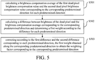
- Block S103 may include Blocks S501 to S503 as shown in FIG. 5 .
- a brightness compensation average of the first dead pixel brightness compensation value and the second dead pixel brightness compensation value corresponding to the corresponding predetermined direction is calculated.
- a corresponding brightness compensation average is d i ⁇ + d i + 2 .
- the difference between the brightness of the dead pixel and the brightness compensation average corresponding to the corresponding predetermined direction is calculated and a first weight is determined according to the difference.
- the first weight is determined according to ⁇ _ abs i .
- the first weight weights i corresponding to each ⁇ _ abs i may be determined according to a preset rule.
- the preset rule of the first weight depends on the needs in practical applications.
- the first weight may be set to be small if the brightness of the dead pixel is higher than that of other pixel dots and ⁇ _abs i is large; the first weight may be set to be large if the brightness of the dead pixel is lower than that of other pixel dots and is small.
- weight _ table i LUT ( index , ⁇ _ abs i , weights i ) .
- the first weight obtained along the corresponding predetermined direction is corrected to obtain a weighting factor corresponding to the corresponding predetermined direction.
- the first difference, the second difference, and the first weight are representative of effects on the dead pixel compensation in aspects of the difference between compensation values at the two sides of the dead pixel, the difference between brightness changing trends at the two sides of the dead pixel, and the difference between the brightness of the dead pixel and the compensation value, respectively.
- the embodiments of the present disclosure generate the weighting factor based on the first difference, the second difference, and the first weight. In such a way, the dead pixel compensation takes into consideration the aforesaid three aspects and thus the compensation result is improved.
- different algorithms may be chosen to calculate the weighting factor using the first difference, the second difference, and the first weight according to a situation of the dead pixel on the image sensor.
- the first difference, the second difference, and the first weight corresponding to the direction may be multiplied together to obtain a corresponding weighting factor.
- the correction may be carried out by other algorithms.
- a correction coefficient is obtained by calculations on the first difference and the second difference based on a preset algorithm, and the first weight is multiplied by the correction coefficient to obtain a corresponding weighting factor.
- the dead pixel brightness compensation values corresponding to the two sides of the dead pixel along each predetermined direction are subjected to a weighting calculation based on the weighting factor to obtain a compensation result for the dead pixel.
- an average of the dead pixel brightness compensation values corresponding to the two sides of the dead pixel along each predetermined direction may be calculated. Then, the average of the dead pixel brightness compensation values corresponding to the two sides of the dead pixel along each predetermined direction is subjected to the weighting calculation based on the weighting factor, and the dead pixel is compensated according to the calculation result.
- the brightness changing trends at the two sides of the dead pixel along each predetermined direction are estimated as well as their difference.
- the dead pixel brightness compensation values corresponding to the two sides of the dead pixel are estimated as well as their difference.
- the two differences are used to determine the weighting factor used to compensate the dead pixel.
- the compensation values corresponding to the respective directions are subjected to the weighting calculation based on the weighting factor.
- the obtained compensation result and other pixel dots are varied more uniform and the effect is better. The effect is outstanding especially in compensation and correction on a static dead pixel in a complex picture.
- FIG. 6a is a schematic diagram illustrating image data that is to be compensated in accordance with an embodiment of the present disclosure
- FIG. 6b is a schematic diagram illustrating a compensation result of the image data shown in FIG. 6a using a traditional approach
- FIG. 6c is a schematic diagram illustrating a compensation result of the image data shown in FIG. 6a in accordance with an embodiment of the present disclosure.
- the afore-mentioned plural predetermined directions are illustrated by the directions shown in FIG. 2b .
- the present disclosure is not limited to the directions shown in FIG. 2b .
- the illustrated directions can be extended to other directions, which are not further detailed herein.
- the present disclosure also provides a device for compensating dead pixels of an image.
- FIG. 7 is a schematic structural diagram illustrating a device for compensating dead pixels of an image in accordance with an embodiment of the present disclosure.
- the dead pixel compensation device of the embodiment of the present disclosure includes an estimating module 10, a first determining module 20, a second determining module 30, a third determining module 40, and a compensating module 50.
- the estimating module 10 is configured to estimate brightness changing trends at two sides of a dead pixel for each predetermined direction in image data that is to be compensated.
- the implementation of the estimating module 10 can be referred to the embodiment shown in FIG. 1 .
- the estimating module 10 is configured to obtain a first brightness information of the pixel dots located at a first side of the dead pixel and having a channel different from the dead pixel and obtain a second brightness information of the pixel dots located at a second side of the dead pixel and having a channel different from the dead pixel in a predetermined region and for each predetermined direction, in which the first side and the second side are two sides of the dead pixel along the predetermined direction, and to estimate a first brightness changing trend at the first side of the dead pixel according to the first brightness information and estimate a second brightness changing trend at the second side of the dead pixel is estimated according to the second brightness information.
- the first determining module 20 is configured to determine dead pixel brightness compensation values corresponding to the two sides of the dead pixel along the corresponding predetermined direction for each predetermined direction in the image data that is to be compensated.
- the implementation of the first determining module 20 can be referred to the embodiment shown in FIG. 1 .
- the first determining module 20 is configured to obtain a third brightness information of the pixel dots located at the first side of the dead pixel and having the same channel as the dead pixel and obtain a fourth brightness information of the pixel dots located at the second side of the dead pixel and having the same channel as the dead pixel in the predetermined region and for each predetermined direction, and to determine a first dead pixel brightness compensation value according to the third brightness information and the brightness changing trend at the first side of the dead pixel and determine a second dead pixel brightness compensation value according to the fourth brightness information and the brightness changing trend at the second side of the dead pixel.
- the second determining module 30 is configured to determine a first difference between the brightness changing trends at the two sides of the dead pixel along each predetermined direction and determine a second difference between the dead pixel brightness compensation values at the two sides of the dead pixel along each predetermined direction.
- the implementation of the second determining module 30 can be referred to the embodiment shown in FIG. 1 .
- the third determining module 40 is configured to determine according to the first difference and the second difference obtained along each predetermined direction, a weighting factor of a corresponding predetermined direction.
- the implementation of the third determining module 40 can be referred to the embodiment shown in FIG. 1 .
- the third determining module 40 is configured to calculate a brightness compensation average of the first dead pixel brightness compensation value and the second dead pixel brightness compensation value corresponding to the corresponding predetermined direction for each predetermined direction, calculate the difference between the brightness of the dead pixel and the brightness compensation average corresponding to the corresponding predetermined direction and determine a first weight according to the difference for each predetermined direction, and correct according to the first difference and the second difference corresponding to each predetermined direction, the first weight obtained along the corresponding predetermined direction to obtain a weighting factor corresponding to the corresponding predetermined direction.
- the compensating module 50 is configured to subject the dead pixel brightness compensation values corresponding to the two sides of the dead pixel along each predetermined direction to a weighting calculation based on the weighting factor to obtain a compensation result for the dead pixel.
- the implementation of the compensating module 50 can be referred to the embodiment shown in FIG. 1 .
- the compensating module 50 is configured to calculate an average of the dead pixel brightness compensation values corresponding to the two sides of the dead pixel along each predetermined direction, subject the average of the dead pixel brightness compensation values corresponding to the two sides of the dead pixel along each predetermined direction to the weighting calculation based on the weighting factor, and compensate the dead pixel according to the calculation result.
- the brightness changing trends at the two sides of the dead pixel along each predetermined direction are estimated as well as their difference.
- the dead pixel brightness compensation values corresponding to the two sides of the dead pixel are estimated as well as their difference.
- the two differences are used to determine the weighting factor used to compensate the dead pixel.
- the compensation values corresponding to the respective directions are subjected to the weighting calculation based on the weighting factor.
- the obtained compensation result and other pixel dots are varied more uniform and the effect is better. The effect is outstanding especially in compensation and correction on a static dead pixel in a complex picture.
- FIG. 8 is a block diagram illustrating an electronic apparatus 800 in accordance with an exemplary embodiment.
- the electronic apparatus 800 can be a mobile phone, a game controller, a tablet device, a medical equipment, an exercise equipment, or a personal digital assistant (PDA).
- PDA personal digital assistant
- the electronic apparatus 800 may include one or a plurality of the following components: a housing 802, a processor 804, a storage 806, a circuit board 808, and a power circuit 810.
- the circuit board 808 is disposed inside a space defined by the housing 802.
- the processor 804 and the storage 806 are disposed on the circuit board 808.
- the power circuit 810 is configured to supply power to each circuit or device of the electronic apparatus 800.
- the storage 806 is configured to store executable program codes. By reading the executable program codes stored in the storage 806, the processor 804 runs a program corresponding to the executable program codes to execute the dead pixel compensation method of any one of the afore-mentioned embodiments.
- the processor 804 typically controls overall operations of the electronic apparatus 800, such as the operations associated with display, telephone calls, data communications, camera operations, and recording operations.
- the processor 804 may include one or more processor 804 to execute instructions to perform actions at all or part of the blocks in the above described methods.
- the processor 804 may include one or more modules which facilitate the interaction between the processor 804 and other components.
- the processor 804 may include a multimedia module to facilitate the interaction between the multimedia component and the processor 804.
- the storage 806 is configured to store various types of data to support the operation of the electronic apparatus 800. Examples of such data include instructions for any application or method operated on the electronic apparatus 800, contact data, Phonebook data, messages, pictures, video, etc.
- the storage 806 may be implemented using any type of volatile or non-volatile memory devices, or a combination thereof, such as a static random access memory (SRAM), an electrically erasable programmable read-only memory (EEPROM), an erasable programmable read-only memory (EPROM), a programmable read-only memory (PROM), a read-only memory (ROM), a magnetic memory, a flash memory, a magnetic or optical disk.
- SRAM static random access memory
- EEPROM electrically erasable programmable read-only memory
- EPROM erasable programmable read-only memory
- PROM programmable read-only memory
- ROM read-only memory
- magnetic memory a magnetic memory
- flash memory a flash memory
- magnetic or optical disk a magnetic
- the power circuit 810 supplies power to various components of the electronic apparatus 800.
- the power circuit 810 may include a power management system, one or more power sources, and any other component associated with generation, management, and distribution of power for the electronic apparatus 800.
- the electronic apparatus 800 may be implemented by one or more application specific integrated circuits (ASICs), digital signal processors (DSPs), digital signal processing devices (DSPDs), programmable logic devices (PLDs), field programmable gate arrays (FPGAs), controllers, micro-controllers, microprocessors, or other electronic components, for performing the above described methods.
- ASICs application specific integrated circuits
- DSPs digital signal processors
- DSPDs digital signal processing devices
- PLDs programmable logic devices
- FPGAs field programmable gate arrays
- controllers micro-controllers, microprocessors, or other electronic components, for performing the above described methods.
- non-transitory computer-readable storage medium including instructions, such as included in the storage 806, executable by the processor 804 of the electronic apparatus 800 for performing the above-described methods.
- the non-transitory computer-readable storage medium may be a ROM, a random access memory (RAM), a CD-ROM, a magnetic tape, a floppy disc, an optical data storage device, and the like.
Landscapes
- Engineering & Computer Science (AREA)
- Multimedia (AREA)
- Signal Processing (AREA)
- Physics & Mathematics (AREA)
- Spectroscopy & Molecular Physics (AREA)
- General Physics & Mathematics (AREA)
- Theoretical Computer Science (AREA)
- Image Processing (AREA)
- Control Of Indicators Other Than Cathode Ray Tubes (AREA)
- Transforming Electric Information Into Light Information (AREA)
- Testing, Inspecting, Measuring Of Stereoscopic Televisions And Televisions (AREA)
- Controls And Circuits For Display Device (AREA)
Claims (13)
- Verfahren zum Kompensieren von toten Pixeln eines Bildes, umfassend:Bestimmen einer Vielzahl von vorbestimmten Richtungen über ein totes Pixel in Bilddaten hinweg; undSchätzen von Helligkeitsänderungstendenzen auf zwei Seiten des toten Pixels für jede der vorbestimmten Richtungen, und Bestimmen von Helligkeitskompensationswerten für tote Pixel, die den beiden Seiten des toten Pixels entlang jeder der vorbestimmten Richtungen entsprechen, basierend auf den geschätzten Helligkeitsänderungstendenzen;dadurch gekennzeichnet, dass das Verfahren ferner umfasst:für jede der vorbestimmten Richtungen, Bestimmen einer ersten Differenz zwischen den Helligkeitsänderungstendenzen auf den beiden Seiten des toten Pixels entlang der vorbestimmten Richtung, und einer zweiten Differenz zwischen den Helligkeitskompensationswerten des toten Pixels auf den beiden Seiten des toten Pixels entlang der vorbestimmten Richtung;für jede der vorbestimmten Richtungen, entsprechend der ersten Differenz und der zweiten Differenz, die entlang der vorbestimmten Richtung beschafft werden,Korrigieren eines Gewichts, das durch Anwenden einer voreingestellten Regel auf die Differenz zwischen der Helligkeit des toten Pixels und dem Mittelwert der beiden Helligkeitskompensationswerte für die vorbestimmte Richtung beschafft wird, um einen Gewichtungsfaktor für die vorbestimmte Richtung zu bestimmen;Unterziehen des Mittelwerts der Helligkeitskompensationswerte des toten Pixels, die den beiden Seiten des toten Pixels entlang jeder vorbestimmten Richtung entsprechen, einer Gewichtungsberechnung basierend auf den jeweiligen Gewichtungsfaktoren, um ein Kompensationsergebnis für das tote Pixel zu beschaffen; undKompensieren des toten Pixels.
- Verfahren nach Anspruch 1, dadurch gekennzeichnet, dass das Schätzen der Helligkeitsänderungstendenzen auf den beiden Seiten des toten Pixels für jede vorbestimmte Richtung umfasst:in einem vorbestimmten Bereich und für jede vorbestimmte Richtung, Beschaffen einer ersten Helligkeitsinformation von Pixelpunkten, die sich auf einer ersten Seite des toten Pixels befinden und eine andere Farbe als das tote Pixel aufweisen, und einer zweiten Helligkeitsinformation der Pixelpunkte, die sich auf einer zweiten Seite des toten Pixels befinden und eine andere Farbe als das tote Pixel aufweisen, wobei die erste Seite und die zweite Seite zwei Seiten des toten Pixels entlang der vorbestimmten Richtung sind, wobei die erste Helligkeitsinformation und die zweite Helligkeitsinformation aus einer gleichen Farbe von Pixelpunkten beschafft werden; undSchätzen einer ersten Helligkeitsänderungstendenz auf der ersten Seite des toten Pixels gemäß der ersten Helligkeitsinformation und Schätzen einer zweiten Helligkeitsänderungstendenz auf der zweiten Seite des toten Pixels gemäß der zweiten Helligkeitsinformation.
- Verfahren nach Anspruch 1, dadurch gekennzeichnet, dass das Bestimmen der Helligkeitskompensationswerte für tote Pixel, die den beiden Seiten des toten Pixels entlang jeder der vorbestimmten Richtungen entsprechen, umfasst:in einem vorbestimmten Bereich und für die vorbestimmte Richtung, Beschaffen einer ersten Helligkeitsinformation von Pixelpunkten, die sich auf einer ersten Seite des toten Pixels befinden und die gleiche Farbe wie das tote Pixel aufweisen, und einer zweiten Helligkeitsinformation der Pixelpunkte, die sich auf einer zweiten Seite des toten Pixels befinden und die gleiche Farbe wie das tote Pixel aufweisen; undBestimmen eines ersten Helligkeitskompensationswertes für tote Pixel gemäß der ersten Helligkeitsinformation und der Helligkeitsänderungstendenz auf der ersten Seite des toten Pixels, und Bestimmen eines zweiten Helligkeitskompensationswertes für tote Pixel gemäß der zweiten Helligkeitsinformation und der Helligkeitsänderungstendenz auf der zweiten Seite des toten Pixels.
- Verfahren nach Anspruch 3, dadurch gekennzeichnet, dass das Bestimmen des Gewichtungsfaktors für jede der vorbestimmten Richtungen umfasst:
Korrigieren des entlang der vorbestimmten Richtung beschafften Gewichts durch Multiplizieren des Gewichts mit dem Korrekturkoeffizienten, um den Gewichtungsfaktor für die vorbestimmte Richtung zu beschaffen. - Vorrichtung zum Kompensieren von toten Pixeln eines Bildes, umfassend:einen Prozessor (804); undeinen Speicher (806), der mit dem Prozessor (804) verbunden ist, wobei der Speicher (806) eine Vielzahl von Programmbefehlen umfasst, die von dem Prozessor (804) ausgeführt werden können, der konfiguriert ist, um ein Verfahren auszuführen, wobei das Verfahren umfasst:Bestimmen einer Vielzahl von vorbestimmten Richtungen über ein totes Pixel in Bilddaten hinweg ;Schätzen von Helligkeitsänderungstendenzen auf zwei Seiten des toten Pixels für jede der vorbestimmten Richtungen;Bestimmen von Helligkeitskompensationswerten für tote Pixel, die den beiden Seiten des toten Pixels entlang jeder der vorbestimmten Richtungen entsprechen, basierend auf den geschätzten Helligkeitsänderungstendenzen;dadurch gekennzeichnet, dass das Verfahren ferner umfasst:für jede der vorbestimmten Richtungen, Bestimmen einer ersten Differenz zwischen den Helligkeitsänderungstendenzen auf den beiden Seiten des toten Pixels entlang der vorbestimmten Richtung, und einer zweiten Differenz zwischen den Helligkeitskompensationswerten für tote Pixel auf den beiden Seiten des toten Pixels entlang der vorbestimmten Richtung;für jede der vorbestimmten Richtungen, entsprechend der ersten Differenz und der zweiten Differenz, die entlang der vorbestimmten Richtung beschafft werden,Korrigieren eines Gewichts, das durch Anwenden einer voreingestellten Regel auf die Differenz zwischen der Helligkeit des toten Pixels und dem Mittelwert der beiden Helligkeitskompensationswerte für die vorbestimmte Richtung beschafft wird, um einen Gewichtungsfaktor für die vorbestimmte Richtung zu bestimmen;Unterziehen des Mittelwerts der Helligkeitskompensationswerte des toten Pixels, die den beiden Seiten des toten Pixels entlang jeder vorbestimmten Richtung entsprechen, einer Gewichtungsberechnung basierend auf den jeweiligen Gewichtungsfaktoren, um ein Kompensationsergebnis für das tote Pixel zu beschaffen; undKompensieren des toten Pixels.
- Vorrichtung nach Anspruch 5, dadurch gekennzeichnet, dass das Schätzen der Helligkeitsänderungstendenzen auf den beiden Seiten des toten Pixels für jede vorbestimmte Richtung umfasst: in einem vorbestimmten Bereich und für jede vorbestimmte Richtung, Beschaffen einer ersten Helligkeitsinformation von Pixelpunkten, die sich auf einer ersten Seite des toten Pixels befinden und eine andere Farbe als das tote Pixel aufweisen, und einer zweiten Helligkeitsinformation der Pixelpunkte, die sich auf einer zweiten Seite des toten Pixels befinden und eine andere Farbe als das tote Pixel aufweisen, wobei die erste Seite und die zweite Seite zwei Seiten des toten Pixels entlang der vorbestimmten Richtung sind, wobei die erste Helligkeitsinformation und die zweite Helligkeitsinformation aus einer gleichen Farbe von Pixelpunkten beschafft werden, und das Schätzen einer ersten Helligkeitsänderungstendenz auf der ersten Seite des toten Pixels gemäß der ersten Helligkeitsinformation und das Schätzen einer zweiten Helligkeitsänderungstendenz auf der zweiten Seite des toten Pixels gemäß der zweiten Helligkeitsinformation geschätzt wird.
- Vorrichtung nach Anspruch 5, dadurch gekennzeichnet, dass das Bestimmen der Helligkeitskompensationswerte für tote Pixel, die den beiden Seiten des toten Pixels entlang jeder der vorbestimmten Richtungen entsprechen, umfasst: Beschaffen, in einem vorbestimmten Bereich und für die vorbestimmte Richtung, einer ersten Helligkeitsinformation von Pixelpunkten, die sich auf einer ersten Seite des toten Pixels befinden und die gleiche Farbe wie das tote Pixel aufweisen, und einer zweiten Helligkeitsinformation der Pixelpunkte, die sich auf einer zweiten Seite des toten Pixels befinden und die gleiche Farbe wie das tote Pixel aufweisen, und Bestimmen eines ersten Helligkeitskompensationswertes für tote Pixel gemäß der ersten Helligkeitsinformation und der Helligkeitsänderungstendenz auf der ersten Seite des toten Pixels und Bestimmen eines zweiten Helligkeitskompensationswertes für tote Pixel gemäß der zweiten Helligkeitsinformation und der Helligkeitsänderungstendenz auf der zweiten Seite des toten Pixels.
- Vorrichtung nach Anspruch 7, dadurch gekennzeichnet, dass das Bestimmen des Gewichtungsfaktors für jede der vorbestimmten Richtungen umfasst:
Korrigieren des entlang der vorbestimmten Richtung beschafften Gewichts durch Multiplizieren des Gewichts mit dem Korrekturkoeffizienten, um den Gewichtungsfaktor für die vorbestimmte Richtung zu beschaffen. - Vorrichtung nach Anspruch 5, dadurch gekennzeichnet, dass die Vorrichtung ferner ein Gehäuse (802), eine Leiterplatte (808) und eine Leistungsschaltung (810) umfasst, wobei die Leiterplatte (808) innerhalb eines durch ein Gehäuse (802) definierten Raumes angeordnet ist, der Prozessor (804) und der Speicher (806) auf der Leiterplatte (808) angeordnet sind, und die Leistungsschaltung (810) konfiguriert ist, um jede Schaltung der Vorrichtung mit Energie zu versorgen.
- Nichtflüchtiges, computerlesbares Speichermedium, das eine oder mehrere Anweisungen speichert, die durch eine Vorrichtung ausführbar sind, um ein Verfahren zum Kompensieren von toten Pixeln eines Bildes zu implementieren, wobei das Verfahren umfasst:Schätzen von Helligkeitsänderungstendenzen auf zwei Seiten eines toten Pixels für jede einer vorbestimmten Anzahl von Richtungen in Bilddaten, die kompensiert werden sollen, und Bestimmen von Helligkeitskompensationswerten für tote Pixel, die den beiden Seiten des toten Pixels entlang jeder der vorbestimmten Richtungen entsprechen, basierend auf den geschätzten Helligkeitsänderungstendenzen;dadurch gekennzeichnet, dass das Verfahren ferner umfasst:für jede der vorbestimmten Richtungen, Bestimmen einer ersten Differenz zwischen den Helligkeitsänderungstendenzen auf den beiden Seiten des toten Pixels entlang der vorbestimmten Richtung, und einer zweiten Differenz zwischen den Helligkeitskompensationswerten des toten Pixels auf den beiden Seiten des toten Pixels entlang der vorbestimmten Richtung;für jede der vorbestimmten Richtungen, gemäß der ersten Differenz und der zweiten Differenz, die entlang der vorbestimmten Richtung beschafft werden, Korrigieren eines Gewichts, das durch Anwenden einer voreingestellten Regel auf die Differenz zwischen der Helligkeit des toten Pixels und dem Mittelwert der beiden Helligkeitskompensationswerte für die vorbestimmte Richtung beschafft wird, um einen Gewichtungsfaktor für die vorbestimmte Richtung zu bestimmen;Unterziehen des Mittelwerts der Helligkeitskompensationswerte des toten Pixels, die den beiden Seiten des toten Pixels entlang jeder vorbestimmten Richtung entsprechen, einer Gewichtungsberechnung basierend auf den jeweiligen Gewichtungsfaktoren, um ein Kompensationsergebnis für das tote Pixel zu beschaffen; undKompensieren des toten Pixels.
- Nichtflüchtiges, computerlesbares Speichermedium nach Anspruch 10, dadurch gekennzeichnet, dass das Schätzen der Helligkeitsänderungstendenzen auf den beiden Seiten des toten Pixels für jede vorbestimmte Richtung in den zu kompensierenden Bilddaten umfasst:in einem vorbestimmten Bereich und für jede vorbestimmte Richtung, Beschaffen einer ersten Helligkeitsinformation von Pixelpunkten, die sich auf einer ersten Seite des toten Pixels befinden und eine andere Farbe als das tote Pixel aufweisen, und einer zweiten Helligkeitsinformation der Pixelpunkte, die sich auf einer zweiten Seite des toten Pixels befinden und eine andere Farbe als das tote Pixel aufweisen, wobei die erste Seite und die zweite Seite zwei Seiten des toten Pixels entlang der vorbestimmten Richtung sind, wobei die erste Helligkeitsinformation und die zweite Helligkeitsinformation aus einer gleichen Farbe von Pixelpunkten beschafft werden; undSchätzen einer ersten Helligkeitsänderungstendenz auf der ersten Seite des toten Pixels gemäß der ersten Helligkeitsinformation und Schätzen einer zweiten Helligkeitsänderungstendenz auf der zweiten Seite des toten Pixels gemäß der zweiten Helligkeitsinformation.
- Nichtflüchtiges, computerlesbares Speichermedium nach Anspruch 10, dadurch gekennzeichnet, dass das Bestimmen der Helligkeitskompensationswerte für tote Pixel, die den beiden Seiten des toten Pixels entlang jeder der vorbestimmten Richtungen entsprechen, umfasst:in einem vorbestimmten Bereich und für die vorbestimmte Richtung, Beschaffen einer ersten Helligkeitsinformation von Pixelpunkten, die sich auf einer ersten Seite des toten Pixels befinden und die gleiche Farbe wie das tote Pixel aufweisen, und einer ersten Helligkeitsinformation der Pixelpunkte, die sich auf einer zweiten Seite des toten Pixels befinden und die gleiche Farbe wie das tote Pixel aufweisen; undBestimmen eines ersten Helligkeitskompensationswertes für tote Pixel gemäß der ersten Helligkeitsinformation und der Helligkeitsänderungstendenz auf der ersten Seite des toten Pixels, und Bestimmen eines zweiten Helligkeitskompensationswertes für tote Pixel gemäß der zweiten Helligkeitsinformation und der Helligkeitsänderungstendenz auf der zweiten Seite des toten Pixels.
- Nichtflüchtiges, computerlesbares Speichermedium nach Anspruch 12, dadurch gekennzeichnet, dass das Bestimmen des Gewichtungsfaktors für jede der vorbestimmten Richtungen umfasst:
Korrigieren des entlang der vorbestimmten Richtung beschafften Gewichts durch Multiplizieren des Gewichts mit dem Korrekturkoeffizienten, um den Gewichtungsfaktor für die vorbestimmte Richtung zu beschaffen.
Applications Claiming Priority (1)
| Application Number | Priority Date | Filing Date | Title |
|---|---|---|---|
| PCT/CN2016/108081 WO2018098707A1 (zh) | 2016-11-30 | 2016-11-30 | 图像坏点补偿方法、装置和电子设备 |
Publications (2)
| Publication Number | Publication Date |
|---|---|
| EP3331237A1 EP3331237A1 (de) | 2018-06-06 |
| EP3331237B1 true EP3331237B1 (de) | 2019-10-23 |
Family
ID=60387836
Family Applications (1)
| Application Number | Title | Priority Date | Filing Date |
|---|---|---|---|
| EP17201395.5A Active EP3331237B1 (de) | 2016-11-30 | 2017-11-13 | Verfahren und vorrichtung zum kompensieren von toten pixeln eines bildes und nichttransitorisches computerlesbares speichermedium |
Country Status (8)
| Country | Link |
|---|---|
| US (1) | US10438330B2 (de) |
| EP (1) | EP3331237B1 (de) |
| JP (1) | JP6461430B1 (de) |
| KR (1) | KR102049681B1 (de) |
| CN (1) | CN107637068B (de) |
| ES (1) | ES2760980T3 (de) |
| TW (1) | TWI620444B (de) |
| WO (1) | WO2018098707A1 (de) |
Families Citing this family (8)
| Publication number | Priority date | Publication date | Assignee | Title |
|---|---|---|---|---|
| KR102561172B1 (ko) * | 2018-11-22 | 2023-07-31 | 삼성전자주식회사 | 디스플레이 내에 카메라 모듈이 포함된 전자 장치 및 상기 카메라 모듈 주변의 이미지를 보정하는 방법 |
| CN109935206B (zh) * | 2019-04-15 | 2021-08-20 | 京东方科技集团股份有限公司 | 基于神经网络的显示器件亮度补偿方法、装置及设备 |
| CN113362781A (zh) * | 2021-06-23 | 2021-09-07 | 合肥维信诺科技有限公司 | 显示面板的亮度补偿方法及亮度补偿系统 |
| US12419602B2 (en) | 2021-09-07 | 2025-09-23 | The Board Of Regents Of The University Of Oklahoma | Dead detector element detection |
| CN114666575A (zh) * | 2022-04-27 | 2022-06-24 | 四川创安微电子有限公司 | 一种基于图像传感器的坏点检测及补偿方法 |
| US12536615B2 (en) * | 2022-12-20 | 2026-01-27 | Samsung Electronics Co., Ltd. | Bad pixel correction in image processing applications or other applications |
| EP4622288A4 (de) * | 2023-01-31 | 2026-01-21 | Samsung Electronics Co Ltd | Kameramodul, verfahren zur korrektur von bildern durch kameramodul und elektronische vorrichtung mit kameramodul |
| CN120852426B (zh) * | 2025-09-23 | 2025-11-28 | 深圳市鑫信腾科技股份有限公司 | 一种缺陷检测方法以及相关设备 |
Family Cites Families (25)
| Publication number | Priority date | Publication date | Assignee | Title |
|---|---|---|---|---|
| US6118846A (en) * | 1999-02-23 | 2000-09-12 | Direct Radiography Corp. | Bad pixel column processing in a radiation detection panel |
| US6618115B1 (en) * | 1999-11-19 | 2003-09-09 | Semiconductor Energy Laboratory Co., Ltd. | Defective pixel compensation system and display device using the system |
| US7034873B2 (en) * | 2001-06-29 | 2006-04-25 | Vanguard International Semiconductor Corporation | Pixel defect correction in a CMOS active pixel image sensor |
| US20030117507A1 (en) | 2001-12-21 | 2003-06-26 | Nasser Kehtarnavaz | Color filter array interpolation |
| JP4350706B2 (ja) | 2003-03-28 | 2009-10-21 | オリンパス株式会社 | 画像処理装置及び画像処理プログラム |
| JP2004320128A (ja) * | 2003-04-11 | 2004-11-11 | Mega Chips Corp | 欠陥画素補正装置 |
| JP3952301B2 (ja) * | 2003-08-29 | 2007-08-01 | ノーリツ鋼機株式会社 | 画像処理装置、方法、及びプログラム |
| JP4239094B2 (ja) | 2004-03-03 | 2009-03-18 | ノーリツ鋼機株式会社 | 画像処理装置、方法、及びプログラム |
| JP4617870B2 (ja) * | 2004-12-22 | 2011-01-26 | ソニー株式会社 | 撮像装置および方法、並びにプログラム |
| CN100366053C (zh) * | 2005-04-08 | 2008-01-30 | 北京中星微电子有限公司 | 一种对数字图像进行坏点补偿的方法 |
| TWI283833B (en) * | 2005-07-07 | 2007-07-11 | Sunplus Technology Co Ltd | Color image dead pixel calibration method and its system |
| US7969488B2 (en) * | 2005-08-03 | 2011-06-28 | Micron Technologies, Inc. | Correction of cluster defects in imagers |
| TWI437878B (zh) * | 2007-11-20 | 2014-05-11 | 廣達電腦股份有限公司 | 用以校正影像訊號中壞點之方法及電路 |
| CN101452573B (zh) | 2007-12-04 | 2013-01-30 | 比亚迪股份有限公司 | 一种图像边缘增强方法 |
| JP5655355B2 (ja) | 2009-11-02 | 2015-01-21 | ソニー株式会社 | 画素欠陥補正装置、撮像装置、画素欠陥補正方法、およびプログラム |
| CN102625133B (zh) * | 2011-01-31 | 2014-11-05 | 英属开曼群岛商恒景科技股份有限公司 | 影像感测坏像素点的检测方法 |
| JP6046927B2 (ja) | 2011-08-09 | 2016-12-21 | キヤノン株式会社 | 画像処理装置及びその制御方法 |
| JP5898428B2 (ja) | 2011-08-09 | 2016-04-06 | キヤノン株式会社 | 画像処理装置及びその制御方法 |
| US8891866B2 (en) * | 2011-08-31 | 2014-11-18 | Sony Corporation | Image processing apparatus, image processing method, and program |
| JP2013066157A (ja) | 2011-08-31 | 2013-04-11 | Sony Corp | 画像処理装置、および画像処理方法、並びにプログラム |
| US9743057B2 (en) * | 2012-05-31 | 2017-08-22 | Apple Inc. | Systems and methods for lens shading correction |
| GB2521408B (en) * | 2013-12-18 | 2015-12-16 | Imagination Tech Ltd | Defective pixel fixing |
| CN103676236B (zh) * | 2013-12-18 | 2017-01-04 | 合肥京东方光电科技有限公司 | 一种修复缺陷像素的方法、系统及显示面板 |
| JP6525522B2 (ja) | 2014-07-10 | 2019-06-05 | キヤノン株式会社 | 画像処理装置および画像処理方法 |
| CN105430385B (zh) * | 2015-12-14 | 2017-06-30 | 上海富瀚微电子股份有限公司 | 一种图像传感器坏点检测和校正的方法及装置 |
-
2016
- 2016-11-30 CN CN201680006799.2A patent/CN107637068B/zh not_active Expired - Fee Related
- 2016-11-30 WO PCT/CN2016/108081 patent/WO2018098707A1/zh not_active Ceased
- 2016-11-30 JP JP2018515872A patent/JP6461430B1/ja not_active Expired - Fee Related
- 2016-11-30 KR KR1020187007783A patent/KR102049681B1/ko active Active
-
2017
- 2017-10-31 TW TW106137660A patent/TWI620444B/zh active
- 2017-11-09 US US15/808,078 patent/US10438330B2/en active Active
- 2017-11-13 ES ES17201395T patent/ES2760980T3/es active Active
- 2017-11-13 EP EP17201395.5A patent/EP3331237B1/de active Active
Non-Patent Citations (1)
| Title |
|---|
| None * |
Also Published As
| Publication number | Publication date |
|---|---|
| EP3331237A1 (de) | 2018-06-06 |
| US20180150942A1 (en) | 2018-05-31 |
| ES2760980T3 (es) | 2020-05-18 |
| KR102049681B1 (ko) | 2019-11-27 |
| CN107637068B (zh) | 2019-10-25 |
| KR20180080180A (ko) | 2018-07-11 |
| CN107637068A (zh) | 2018-01-26 |
| JP6461430B1 (ja) | 2019-01-30 |
| TW201822530A (zh) | 2018-06-16 |
| JP2019507361A (ja) | 2019-03-14 |
| WO2018098707A1 (zh) | 2018-06-07 |
| TWI620444B (zh) | 2018-04-01 |
| US10438330B2 (en) | 2019-10-08 |
Similar Documents
| Publication | Publication Date | Title |
|---|---|---|
| EP3331237B1 (de) | Verfahren und vorrichtung zum kompensieren von toten pixeln eines bildes und nichttransitorisches computerlesbares speichermedium | |
| US10043443B2 (en) | Display device and method and apparatus for compensating luminance of display device | |
| US7773828B2 (en) | Method and device for stabilizing an image by applying an affine transform based on a weighted average of motion vectors | |
| WO2020093685A1 (zh) | 用于显示屏的补偿方法、补偿装置和显示装置 | |
| US9837011B2 (en) | Optical compensation system for performing smear compensation of a display device and optical compensation method thereof | |
| KR20190052195A (ko) | 휘도 불균일 보상 방법 및 이를 채용한 표시 장치 | |
| CN111292701A (zh) | 显示面板补偿方法及装置 | |
| US9055223B2 (en) | Digital image stabilization method and imaging device using the same | |
| CN113590071B (zh) | 基于抖动处理的图像处理方法、装置、计算机设备及介质 | |
| US12148186B2 (en) | System and method for learning tone curves for local image enhancement | |
| US20210243395A1 (en) | Image pickup apparatus for inferring noise and learning device | |
| US20060228102A1 (en) | Photographing apparatus and method for compensating brightness of an image | |
| CN116164837B (zh) | 一种环境光检测方法、装置、设备及存储介质 | |
| KR101818104B1 (ko) | 카메라 및 카메라 캘리브레이션 방법 | |
| CN116913226B (zh) | 显示面板的亮度补偿方法及装置、计算设备 | |
| US12488504B2 (en) | Apparatus and method for performing color transformation on raw sensor images | |
| CN118200729A (zh) | 摄像机预置位的生成方法及装置 | |
| US20120099786A1 (en) | Electronic systems and methods for repairing scar images | |
| US20180365816A1 (en) | Method of adjusting bitrate of image and image capturing apparatus, and method of generating bitrate-adjusted image | |
| US20230093967A1 (en) | Purple-fringe correction method and purple-fringe correction device | |
| US20250191142A1 (en) | Radiometric compensation for temporal noise reduction in video | |
| KR20160079246A (ko) | 얼룩 보상 장치 및 그를 가지는 평판 표시 장치의 화질 보상 장치 | |
| US11750938B2 (en) | Image pickup apparatus that can assist user, control method therefor, and storage medium storing control program therefor | |
| CN116740027B (zh) | 油浸设备的故障检测方法、装置及其计算机设备 | |
| CN111462676B (zh) | 电压的确定方法及其确定装置、显示装置 |
Legal Events
| Date | Code | Title | Description |
|---|---|---|---|
| PUAI | Public reference made under article 153(3) epc to a published international application that has entered the european phase |
Free format text: ORIGINAL CODE: 0009012 |
|
| STAA | Information on the status of an ep patent application or granted ep patent |
Free format text: STATUS: REQUEST FOR EXAMINATION WAS MADE |
|
| 17P | Request for examination filed |
Effective date: 20171113 |
|
| AK | Designated contracting states |
Kind code of ref document: A1 Designated state(s): AL AT BE BG CH CY CZ DE DK EE ES FI FR GB GR HR HU IE IS IT LI LT LU LV MC MK MT NL NO PL PT RO RS SE SI SK SM TR |
|
| AX | Request for extension of the european patent |
Extension state: BA ME |
|
| STAA | Information on the status of an ep patent application or granted ep patent |
Free format text: STATUS: EXAMINATION IS IN PROGRESS |
|
| 17Q | First examination report despatched |
Effective date: 20190131 |
|
| GRAP | Despatch of communication of intention to grant a patent |
Free format text: ORIGINAL CODE: EPIDOSNIGR1 |
|
| STAA | Information on the status of an ep patent application or granted ep patent |
Free format text: STATUS: GRANT OF PATENT IS INTENDED |
|
| RIC1 | Information provided on ipc code assigned before grant |
Ipc: H04N 9/04 20060101ALI20190624BHEP Ipc: G06T 5/00 20060101ALI20190624BHEP Ipc: H04N 5/367 20110101AFI20190624BHEP |
|
| INTG | Intention to grant announced |
Effective date: 20190711 |
|
| GRAS | Grant fee paid |
Free format text: ORIGINAL CODE: EPIDOSNIGR3 |
|
| GRAA | (expected) grant |
Free format text: ORIGINAL CODE: 0009210 |
|
| STAA | Information on the status of an ep patent application or granted ep patent |
Free format text: STATUS: THE PATENT HAS BEEN GRANTED |
|
| AK | Designated contracting states |
Kind code of ref document: B1 Designated state(s): AL AT BE BG CH CY CZ DE DK EE ES FI FR GB GR HR HU IE IS IT LI LT LU LV MC MK MT NL NO PL PT RO RS SE SI SK SM TR |
|
| REG | Reference to a national code |
Ref country code: GB Ref legal event code: FG4D |
|
| REG | Reference to a national code |
Ref country code: CH Ref legal event code: EP |
|
| REG | Reference to a national code |
Ref country code: IE Ref legal event code: FG4D |
|
| REG | Reference to a national code |
Ref country code: DE Ref legal event code: R096 Ref document number: 602017008029 Country of ref document: DE |
|
| REG | Reference to a national code |
Ref country code: AT Ref legal event code: REF Ref document number: 1194996 Country of ref document: AT Kind code of ref document: T Effective date: 20191115 |
|
| REG | Reference to a national code |
Ref country code: NL Ref legal event code: FP |
|
| RAP2 | Party data changed (patent owner data changed or rights of a patent transferred) |
Owner name: GUANGDONG OPPO MOBILE TELECOMMUNICATIONS CORP., LT |
|
| REG | Reference to a national code |
Ref country code: LT Ref legal event code: MG4D |
|
| PG25 | Lapsed in a contracting state [announced via postgrant information from national office to epo] |
Ref country code: PT Free format text: LAPSE BECAUSE OF FAILURE TO SUBMIT A TRANSLATION OF THE DESCRIPTION OR TO PAY THE FEE WITHIN THE PRESCRIBED TIME-LIMIT Effective date: 20200224 Ref country code: BG Free format text: LAPSE BECAUSE OF FAILURE TO SUBMIT A TRANSLATION OF THE DESCRIPTION OR TO PAY THE FEE WITHIN THE PRESCRIBED TIME-LIMIT Effective date: 20200123 Ref country code: FI Free format text: LAPSE BECAUSE OF FAILURE TO SUBMIT A TRANSLATION OF THE DESCRIPTION OR TO PAY THE FEE WITHIN THE PRESCRIBED TIME-LIMIT Effective date: 20191023 Ref country code: GR Free format text: LAPSE BECAUSE OF FAILURE TO SUBMIT A TRANSLATION OF THE DESCRIPTION OR TO PAY THE FEE WITHIN THE PRESCRIBED TIME-LIMIT Effective date: 20200124 Ref country code: NO Free format text: LAPSE BECAUSE OF FAILURE TO SUBMIT A TRANSLATION OF THE DESCRIPTION OR TO PAY THE FEE WITHIN THE PRESCRIBED TIME-LIMIT Effective date: 20200123 Ref country code: PL Free format text: LAPSE BECAUSE OF FAILURE TO SUBMIT A TRANSLATION OF THE DESCRIPTION OR TO PAY THE FEE WITHIN THE PRESCRIBED TIME-LIMIT Effective date: 20191023 Ref country code: SE Free format text: LAPSE BECAUSE OF FAILURE TO SUBMIT A TRANSLATION OF THE DESCRIPTION OR TO PAY THE FEE WITHIN THE PRESCRIBED TIME-LIMIT Effective date: 20191023 Ref country code: LV Free format text: LAPSE BECAUSE OF FAILURE TO SUBMIT A TRANSLATION OF THE DESCRIPTION OR TO PAY THE FEE WITHIN THE PRESCRIBED TIME-LIMIT Effective date: 20191023 Ref country code: LT Free format text: LAPSE BECAUSE OF FAILURE TO SUBMIT A TRANSLATION OF THE DESCRIPTION OR TO PAY THE FEE WITHIN THE PRESCRIBED TIME-LIMIT Effective date: 20191023 |
|
| REG | Reference to a national code |
Ref country code: ES Ref legal event code: FG2A Ref document number: 2760980 Country of ref document: ES Kind code of ref document: T3 Effective date: 20200518 |
|
| PG25 | Lapsed in a contracting state [announced via postgrant information from national office to epo] |
Ref country code: RS Free format text: LAPSE BECAUSE OF FAILURE TO SUBMIT A TRANSLATION OF THE DESCRIPTION OR TO PAY THE FEE WITHIN THE PRESCRIBED TIME-LIMIT Effective date: 20191023 Ref country code: IS Free format text: LAPSE BECAUSE OF FAILURE TO SUBMIT A TRANSLATION OF THE DESCRIPTION OR TO PAY THE FEE WITHIN THE PRESCRIBED TIME-LIMIT Effective date: 20200224 Ref country code: HR Free format text: LAPSE BECAUSE OF FAILURE TO SUBMIT A TRANSLATION OF THE DESCRIPTION OR TO PAY THE FEE WITHIN THE PRESCRIBED TIME-LIMIT Effective date: 20191023 |
|
| PG25 | Lapsed in a contracting state [announced via postgrant information from national office to epo] |
Ref country code: AL Free format text: LAPSE BECAUSE OF FAILURE TO SUBMIT A TRANSLATION OF THE DESCRIPTION OR TO PAY THE FEE WITHIN THE PRESCRIBED TIME-LIMIT Effective date: 20191023 |
|
| REG | Reference to a national code |
Ref country code: DE Ref legal event code: R097 Ref document number: 602017008029 Country of ref document: DE |
|
| PG2D | Information on lapse in contracting state deleted |
Ref country code: IS |
|
| PG25 | Lapsed in a contracting state [announced via postgrant information from national office to epo] |
Ref country code: DK Free format text: LAPSE BECAUSE OF FAILURE TO SUBMIT A TRANSLATION OF THE DESCRIPTION OR TO PAY THE FEE WITHIN THE PRESCRIBED TIME-LIMIT Effective date: 20191023 Ref country code: EE Free format text: LAPSE BECAUSE OF FAILURE TO SUBMIT A TRANSLATION OF THE DESCRIPTION OR TO PAY THE FEE WITHIN THE PRESCRIBED TIME-LIMIT Effective date: 20191023 Ref country code: RO Free format text: LAPSE BECAUSE OF FAILURE TO SUBMIT A TRANSLATION OF THE DESCRIPTION OR TO PAY THE FEE WITHIN THE PRESCRIBED TIME-LIMIT Effective date: 20191023 Ref country code: CZ Free format text: LAPSE BECAUSE OF FAILURE TO SUBMIT A TRANSLATION OF THE DESCRIPTION OR TO PAY THE FEE WITHIN THE PRESCRIBED TIME-LIMIT Effective date: 20191023 Ref country code: MC Free format text: LAPSE BECAUSE OF FAILURE TO SUBMIT A TRANSLATION OF THE DESCRIPTION OR TO PAY THE FEE WITHIN THE PRESCRIBED TIME-LIMIT Effective date: 20191023 Ref country code: LU Free format text: LAPSE BECAUSE OF NON-PAYMENT OF DUE FEES Effective date: 20191113 Ref country code: IS Free format text: LAPSE BECAUSE OF FAILURE TO SUBMIT A TRANSLATION OF THE DESCRIPTION OR TO PAY THE FEE WITHIN THE PRESCRIBED TIME-LIMIT Effective date: 20200223 |
|
| REG | Reference to a national code |
Ref country code: AT Ref legal event code: MK05 Ref document number: 1194996 Country of ref document: AT Kind code of ref document: T Effective date: 20191023 |
|
| REG | Reference to a national code |
Ref country code: BE Ref legal event code: MM Effective date: 20191130 |
|
| PLBE | No opposition filed within time limit |
Free format text: ORIGINAL CODE: 0009261 |
|
| STAA | Information on the status of an ep patent application or granted ep patent |
Free format text: STATUS: NO OPPOSITION FILED WITHIN TIME LIMIT |
|
| PG25 | Lapsed in a contracting state [announced via postgrant information from national office to epo] |
Ref country code: SM Free format text: LAPSE BECAUSE OF FAILURE TO SUBMIT A TRANSLATION OF THE DESCRIPTION OR TO PAY THE FEE WITHIN THE PRESCRIBED TIME-LIMIT Effective date: 20191023 Ref country code: SK Free format text: LAPSE BECAUSE OF FAILURE TO SUBMIT A TRANSLATION OF THE DESCRIPTION OR TO PAY THE FEE WITHIN THE PRESCRIBED TIME-LIMIT Effective date: 20191023 |
|
| 26N | No opposition filed |
Effective date: 20200724 |
|
| PG25 | Lapsed in a contracting state [announced via postgrant information from national office to epo] |
Ref country code: IE Free format text: LAPSE BECAUSE OF NON-PAYMENT OF DUE FEES Effective date: 20191113 |
|
| PG25 | Lapsed in a contracting state [announced via postgrant information from national office to epo] |
Ref country code: AT Free format text: LAPSE BECAUSE OF FAILURE TO SUBMIT A TRANSLATION OF THE DESCRIPTION OR TO PAY THE FEE WITHIN THE PRESCRIBED TIME-LIMIT Effective date: 20191023 Ref country code: BE Free format text: LAPSE BECAUSE OF NON-PAYMENT OF DUE FEES Effective date: 20191130 Ref country code: SI Free format text: LAPSE BECAUSE OF FAILURE TO SUBMIT A TRANSLATION OF THE DESCRIPTION OR TO PAY THE FEE WITHIN THE PRESCRIBED TIME-LIMIT Effective date: 20191023 |
|
| PG25 | Lapsed in a contracting state [announced via postgrant information from national office to epo] |
Ref country code: CY Free format text: LAPSE BECAUSE OF FAILURE TO SUBMIT A TRANSLATION OF THE DESCRIPTION OR TO PAY THE FEE WITHIN THE PRESCRIBED TIME-LIMIT Effective date: 20191023 |
|
| REG | Reference to a national code |
Ref country code: CH Ref legal event code: PL |
|
| PG25 | Lapsed in a contracting state [announced via postgrant information from national office to epo] |
Ref country code: HU Free format text: LAPSE BECAUSE OF FAILURE TO SUBMIT A TRANSLATION OF THE DESCRIPTION OR TO PAY THE FEE WITHIN THE PRESCRIBED TIME-LIMIT; INVALID AB INITIO Effective date: 20171113 Ref country code: MT Free format text: LAPSE BECAUSE OF FAILURE TO SUBMIT A TRANSLATION OF THE DESCRIPTION OR TO PAY THE FEE WITHIN THE PRESCRIBED TIME-LIMIT Effective date: 20191023 |
|
| PG25 | Lapsed in a contracting state [announced via postgrant information from national office to epo] |
Ref country code: CH Free format text: LAPSE BECAUSE OF NON-PAYMENT OF DUE FEES Effective date: 20201130 Ref country code: LI Free format text: LAPSE BECAUSE OF NON-PAYMENT OF DUE FEES Effective date: 20201130 |
|
| PG25 | Lapsed in a contracting state [announced via postgrant information from national office to epo] |
Ref country code: TR Free format text: LAPSE BECAUSE OF FAILURE TO SUBMIT A TRANSLATION OF THE DESCRIPTION OR TO PAY THE FEE WITHIN THE PRESCRIBED TIME-LIMIT Effective date: 20191023 |
|
| PG25 | Lapsed in a contracting state [announced via postgrant information from national office to epo] |
Ref country code: MK Free format text: LAPSE BECAUSE OF FAILURE TO SUBMIT A TRANSLATION OF THE DESCRIPTION OR TO PAY THE FEE WITHIN THE PRESCRIBED TIME-LIMIT Effective date: 20191023 |
|
| REG | Reference to a national code |
Ref country code: DE Ref legal event code: R079 Ref document number: 602017008029 Country of ref document: DE Free format text: PREVIOUS MAIN CLASS: H04N0005367000 Ipc: H04N0025680000 |
|
| P01 | Opt-out of the competence of the unified patent court (upc) registered |
Effective date: 20230412 |
|
| PGFP | Annual fee paid to national office [announced via postgrant information from national office to epo] |
Ref country code: NL Payment date: 20251127 Year of fee payment: 9 |
|
| PGFP | Annual fee paid to national office [announced via postgrant information from national office to epo] |
Ref country code: DE Payment date: 20251124 Year of fee payment: 9 |
|
| PGFP | Annual fee paid to national office [announced via postgrant information from national office to epo] |
Ref country code: GB Payment date: 20251126 Year of fee payment: 9 |
|
| PGFP | Annual fee paid to national office [announced via postgrant information from national office to epo] |
Ref country code: IT Payment date: 20251120 Year of fee payment: 9 |
|
| PGFP | Annual fee paid to national office [announced via postgrant information from national office to epo] |
Ref country code: FR Payment date: 20251126 Year of fee payment: 9 |
|
| PGFP | Annual fee paid to national office [announced via postgrant information from national office to epo] |
Ref country code: ES Payment date: 20251202 Year of fee payment: 9 |