EP3330992A1 - Elektrisches gleichstromschaltsystem - Google Patents
Elektrisches gleichstromschaltsystem Download PDFInfo
- Publication number
- EP3330992A1 EP3330992A1 EP16202187.7A EP16202187A EP3330992A1 EP 3330992 A1 EP3330992 A1 EP 3330992A1 EP 16202187 A EP16202187 A EP 16202187A EP 3330992 A1 EP3330992 A1 EP 3330992A1
- Authority
- EP
- European Patent Office
- Prior art keywords
- switch
- current
- contact
- electrical
- switching system
- Prior art date
- Legal status (The legal status is an assumption and is not a legal conclusion. Google has not performed a legal analysis and makes no representation as to the accuracy of the status listed.)
- Granted
Links
- 238000002347 injection Methods 0.000 claims abstract description 30
- 239000007924 injection Substances 0.000 claims abstract description 30
- 238000010891 electric arc Methods 0.000 claims abstract description 11
- 239000003990 capacitor Substances 0.000 claims description 19
- XEEYBQQBJWHFJM-UHFFFAOYSA-N Iron Chemical compound [Fe] XEEYBQQBJWHFJM-UHFFFAOYSA-N 0.000 claims description 8
- 229910000831 Steel Inorganic materials 0.000 claims description 5
- 238000000576 coating method Methods 0.000 claims description 5
- 239000010959 steel Substances 0.000 claims description 5
- 229910001369 Brass Inorganic materials 0.000 claims description 4
- 239000010951 brass Substances 0.000 claims description 4
- 229910052742 iron Inorganic materials 0.000 claims description 4
- 238000000034 method Methods 0.000 description 4
- 238000007664 blowing Methods 0.000 description 3
- 239000011248 coating agent Substances 0.000 description 3
- 239000000696 magnetic material Substances 0.000 description 3
- 239000000463 material Substances 0.000 description 3
- 238000005086 pumping Methods 0.000 description 3
- 238000005253 cladding Methods 0.000 description 2
- 239000004065 semiconductor Substances 0.000 description 2
- RYGMFSIKBFXOCR-UHFFFAOYSA-N Copper Chemical compound [Cu] RYGMFSIKBFXOCR-UHFFFAOYSA-N 0.000 description 1
- FYYHWMGAXLPEAU-UHFFFAOYSA-N Magnesium Chemical compound [Mg] FYYHWMGAXLPEAU-UHFFFAOYSA-N 0.000 description 1
- BQCADISMDOOEFD-UHFFFAOYSA-N Silver Chemical compound [Ag] BQCADISMDOOEFD-UHFFFAOYSA-N 0.000 description 1
- HCHKCACWOHOZIP-UHFFFAOYSA-N Zinc Chemical compound [Zn] HCHKCACWOHOZIP-UHFFFAOYSA-N 0.000 description 1
- 239000000853 adhesive Substances 0.000 description 1
- 230000001070 adhesive effect Effects 0.000 description 1
- 239000000956 alloy Substances 0.000 description 1
- 229910045601 alloy Inorganic materials 0.000 description 1
- 230000008033 biological extinction Effects 0.000 description 1
- 230000015572 biosynthetic process Effects 0.000 description 1
- 239000004020 conductor Substances 0.000 description 1
- 238000007796 conventional method Methods 0.000 description 1
- 229910052802 copper Inorganic materials 0.000 description 1
- 239000010949 copper Substances 0.000 description 1
- 230000003247 decreasing effect Effects 0.000 description 1
- 238000002242 deionisation method Methods 0.000 description 1
- PCHJSUWPFVWCPO-UHFFFAOYSA-N gold Chemical compound [Au] PCHJSUWPFVWCPO-UHFFFAOYSA-N 0.000 description 1
- 229910052737 gold Inorganic materials 0.000 description 1
- 239000010931 gold Substances 0.000 description 1
- 238000010438 heat treatment Methods 0.000 description 1
- 229910052749 magnesium Inorganic materials 0.000 description 1
- 239000011777 magnesium Substances 0.000 description 1
- 238000002844 melting Methods 0.000 description 1
- 230000008018 melting Effects 0.000 description 1
- 238000010791 quenching Methods 0.000 description 1
- 230000000171 quenching effect Effects 0.000 description 1
- 238000000926 separation method Methods 0.000 description 1
- 229910052709 silver Inorganic materials 0.000 description 1
- 239000004332 silver Substances 0.000 description 1
- 230000002195 synergetic effect Effects 0.000 description 1
- 230000001960 triggered effect Effects 0.000 description 1
- 238000003466 welding Methods 0.000 description 1
- 229910052725 zinc Inorganic materials 0.000 description 1
- 239000011701 zinc Substances 0.000 description 1
Images


Classifications
-
- H—ELECTRICITY
- H01—ELECTRIC ELEMENTS
- H01H—ELECTRIC SWITCHES; RELAYS; SELECTORS; EMERGENCY PROTECTIVE DEVICES
- H01H33/00—High-tension or heavy-current switches with arc-extinguishing or arc-preventing means
- H01H33/02—Details
- H01H33/59—Circuit arrangements not adapted to a particular application of the switch and not otherwise provided for, e.g. for ensuring operation of the switch at a predetermined point in the ac cycle
- H01H33/596—Circuit arrangements not adapted to a particular application of the switch and not otherwise provided for, e.g. for ensuring operation of the switch at a predetermined point in the ac cycle for interrupting dc
-
- H—ELECTRICITY
- H01—ELECTRIC ELEMENTS
- H01H—ELECTRIC SWITCHES; RELAYS; SELECTORS; EMERGENCY PROTECTIVE DEVICES
- H01H33/00—High-tension or heavy-current switches with arc-extinguishing or arc-preventing means
- H01H33/02—Details
- H01H33/04—Means for extinguishing or preventing arc between current-carrying parts
- H01H33/08—Stationary parts for restricting or subdividing the arc, e.g. barrier plate
- H01H33/10—Metal parts
-
- H—ELECTRICITY
- H01—ELECTRIC ELEMENTS
- H01H—ELECTRIC SWITCHES; RELAYS; SELECTORS; EMERGENCY PROTECTIVE DEVICES
- H01H9/00—Details of switching devices, not covered by groups H01H1/00 - H01H7/00
- H01H9/30—Means for extinguishing or preventing arc between current-carrying parts
- H01H9/34—Stationary parts for restricting or subdividing the arc, e.g. barrier plate
- H01H9/36—Metal parts
-
- H—ELECTRICITY
- H02—GENERATION; CONVERSION OR DISTRIBUTION OF ELECTRIC POWER
- H02H—EMERGENCY PROTECTIVE CIRCUIT ARRANGEMENTS
- H02H3/00—Emergency protective circuit arrangements for automatic disconnection directly responsive to an undesired change from normal electric working condition with or without subsequent reconnection ; integrated protection
- H02H3/16—Emergency protective circuit arrangements for automatic disconnection directly responsive to an undesired change from normal electric working condition with or without subsequent reconnection ; integrated protection responsive to fault current to earth, frame or mass
-
- H—ELECTRICITY
- H02—GENERATION; CONVERSION OR DISTRIBUTION OF ELECTRIC POWER
- H02H—EMERGENCY PROTECTIVE CIRCUIT ARRANGEMENTS
- H02H3/00—Emergency protective circuit arrangements for automatic disconnection directly responsive to an undesired change from normal electric working condition with or without subsequent reconnection ; integrated protection
- H02H3/02—Details
- H02H3/021—Details concerning the disconnection itself, e.g. at a particular instant, particularly at zero value of current, disconnection in a predetermined order
-
- H—ELECTRICITY
- H02—GENERATION; CONVERSION OR DISTRIBUTION OF ELECTRIC POWER
- H02H—EMERGENCY PROTECTIVE CIRCUIT ARRANGEMENTS
- H02H3/00—Emergency protective circuit arrangements for automatic disconnection directly responsive to an undesired change from normal electric working condition with or without subsequent reconnection ; integrated protection
- H02H3/08—Emergency protective circuit arrangements for automatic disconnection directly responsive to an undesired change from normal electric working condition with or without subsequent reconnection ; integrated protection responsive to excess current
- H02H3/087—Emergency protective circuit arrangements for automatic disconnection directly responsive to an undesired change from normal electric working condition with or without subsequent reconnection ; integrated protection responsive to excess current for dc applications
Definitions
- the present disclosure generally relates to an electrical DC switching system for extinguishing an electric arc.
- it relates to an electrical DC switching system of a type that relies on artificial zero-crossings for arc extinguishing purposes.
- Switching systems are used for interrupting a current or protecting an electric circuit in the event of an electrical failure for example due to a short circuit.
- Switching systems may comprise contacts which during normal operation are in mechanical connection. When the contacts are separated from each other a current breaking operation is effected. In addition to separating the contacts, a current breaking operation involves extinguishing an arc between the contacts, and to force the current to zero.
- Alternating current (AC) switching systems utilise the naturally occurring zero-crossings of the alternating current flowing through the switching system for extinguishing the arc.
- Direct current (DC) switching systems cannot utilise natural zero-crossings since there are none. It is known to create artificial zero-crossings for DC switching systems in order to be able to perform a current breaking operation.
- One way to obtain an artificial zero-crossing is by utilising a resonance circuit connected across the contacts.
- the resonance circuit comprises a capacitor which is continually charged by an energy source. The capacitor is charged to obtain a polarity which enables a capacitor discharge current to flow through the contacts in the opposite direction relative to the arc current flowing through the arc.
- the arrangement furthermore comprises a switch which normally is in its open state. When a current breaking operation is effected and the contacts are separated, the switch is closed, wherein the capacitor discharges its electric charge and the resonance circuit provides a current pulse into the contacts.
- the current pulse flows in the opposite direction relative to the arc current.
- an artificial zero-crossing is obtained.
- the arc generated at the contacts which enables the arc current to continue to flow after opening of the separation of the contacts, may be extinguished by deionization of the hot plasma and/or gas in the gap between the contacts. In this manner it is possible to break the arc current.
- the above-described artificial zero-crossing creation requires that the capacitor is charged at all times. Furthermore a power supply is needed to constantly charge the capacitor. Moreover, the artificial zero-crossing provides for only a single chance to successfully extinguish the arc and thus to break the arc current.
- WO 2016/131949 A1 discloses a switching system for breaking a current which allows for several opportunities to successfully extinguish the arc and thus to break the arc current, by providing several subsequent artificial zero-crossings utilising a resonance circuit and switches to use the arc current repeatedly inject a reverse current into the contact arrangement.
- the arc travels across the splitter plates with a voltage between each splitter plate that may be in the order of about a hundredth of the DC voltage source.
- These voltages sum up to a reverse voltage of the same magnitude as that provided by the DC voltage source which feeds the contacts.
- the current can in this manner relatively slowly be decreased from the arc current value to zero.
- a reverse voltage is built up across the splitter plates to thereby obtain a current reduction, relatively slowly reducing the current to zero after the reverse voltage has built up to the level of the DC voltage source.
- a great plurality of splitter plates is needed to build up the required voltage level.
- the number of splitter plates required may for example be in the order of a hundred.
- the current injection approach sets the current to zero by injecting a current in the reverse direction, and when the current is zero the reverse voltage across the splitter plates builds up to the magnitude of the voltage of the DC voltage source.
- the arc extinguishing principle of the current injection approach may hence be seen as the opposite to that of the conventional approach.
- the splitter plates are only used as a means of deionizing the post arc gas and not, as in the conventional case, as a reverse voltage source which sums up to a reverse voltage of the same magnitude as that provided by the DC voltage source which feeds the contacts.
- the number of splitter plates needed is only governed by the withstand ability of the post arc gaps and would in this same example only be about ten.
- the number of splitter plates need not be chosen so large as for the conventional case and hence the potential difference between each adjacent splitter plate is permitted to reach much higher voltage levels than in the conventional case.
- the potential difference between adjacent splitter plates could in particular be in the order of ten higher than in the conventional case. This means that the number of splitter plates could be reduced with about 90% in the current injection case.
- DE 2362089 discloses a type of electric arc quenching plate that consists of a brass-plated sheet of iron or steel. The steel is plated with brass on both sides.
- splitter plates with a certain layered material configuration for example as disclosed in DE 2362089
- a DC switching system based on the DC current injection principle provides a highly synergistic effect compared to when such splitter plates are used with conventional DC switching systems. This enables the reduction of the number of splitter plates by about 90%, thereby significantly reducing the footprint and material cost of a DC switching system.
- an object of the present disclosure is to provide an electrical DC switching system which solves, or at least mitigate, the problems of the prior art.
- an electrical DC switching system for extinguishing an electric arc
- the electrical DC switching system comprises: a contact arrangement having a first contact and a second contact, a current injection circuit including a resonance circuit configured to be connected across the contact arrangement, and a first switch connected to the resonance circuit and to the first contact, wherein the first switch is configured to be switched between an open state and a closed state, wherein in the closed state the first switch is configured to enable an injection current to flow through the resonance circuit in a first flow direction and into the contact arrangement in a direction opposite to a flow direction of a contact arrangement arc current, and an arc chute assembly comprising a plurality of splitter plates configured to extinguish an electric arc across the first contact and the second contact, wherein each splitter plate of the plurality of splitter plates has a layered configuration comprising a magnetic layer and two non-magnetic layers.
- Another advantage is that the withstand voltage between adjacent splitter plates immediately after current zero is considerably higher than the arcing voltage, typically ten times, if non-magnetic material is used in the splitter plates. Hence the number of splitter plates can be reduced to only about one tenth because the sum of the arcing voltages is of no interest as for the conventional approach.
- a third advantage is that the arcing time is considerably reduced preventing severe melting in the splitter plate surfaces and hence short circuiting in between. This will reduce the total heating furthermore and the risk of arc re-ignition inside and outside the arc chute assembly.
- the arcing time reduction is in the order of five to ten times and is a consequence of a relative high frequency of the resonance circuit used for the injection current.
- each splitter plate the magnetic layer is surrounded by the two non-magnetic layers.
- the magnetic layer is a magnetic sheet and the two non-magnetic layers are two non-magnetic sheets and wherein the magnetic sheet and the non-magnetic sheets are arranged in a detachable stacked manner.
- each splitter plate the magnetic layer and the two non-magnetic layers are cladded.
- each splitter plate the two non-magnetic layers are coatings provided on the magnetic layer.
- the magnetic layer is a steel layer or an iron layer.
- each of the two non-magnetic layers is a brass layer.
- the resonance circuit comprises a capacitor and an inductor.
- the current injection circuit comprises a DC power source configured to charge the capacitor when the first switch is in the open position.
- the DC power source is in particular configured to charge the capacitor such that the injection current flowing through the resonance circuit and into the contact arrangement when the first switch is set in the closed state is in the reverse direction in relation to the contact arrangement arc current.
- One embodiment comprises a control system, wherein the current injection circuit comprises a second switch connected to the resonance circuit and to the second contact of the contact arrangement, wherein the second switch is configured to be switched between an open state and a closed state, wherein in the closed state the second switch is configured to enable current to flow through the resonance circuit in a second flow direction opposite to the first flow direction, and a control system, wherein the control system is configured to alternatingly first set the first switch, and then the second switch, first in the closed state and then in the open state upon a current breaking operation, until a current pulse, emanating from energy supplied by the contact arrangement arc current, flowing through the resonance circuit and into the contact arrangement, and thereafter into the splitter plates reaches an amplitude which is equal to or greater than a magnitude of the contact arrangement arc current.
- the control system in each iteration of alternatingly first setting the first switch, and then the second switch, first in the closed state and then in the open state, is configured to: set the first switch in the closed position, enabling a first current pulse to flow through the resonance circuit in the first flow direction, set first the first switch in the open state and then the second switch in the closed state when the first current pulse has become zero to enable a second current pulse to flow through the resonance circuit in the second flow direction, and to set the second switch in the open state when the second current pulse first has become zero.
- the second switch is connected across the resonance circuit.
- the electrical DC switching system comprises a contact arrangement having a movable breaker contact and a fixed contact.
- the breaker contact can be actuated between a closed position in which it is in mechanical contact with the fixed contact and an open position in which the breaker contact is mechanically separated from the fixed contact.
- the movable breaker contact defines a first contact of the contact arrangement and the fixed contact defines a second contact of the contact arrangement.
- the electrical DC switching system comprises a current injection circuit including a resonance circuit, which is an LC-circuit comprising a capacitor and an inductor, and a first switch.
- the inductor may either be an inductor component or the inherent inductance of the conductors to which the capacitor is connected.
- the resonance circuit is configured to be connected across the contact arrangement.
- the first switch is configured to be switched between a closed state and an open state. When in the closed state, an injection current is able to flow through the resonance circuit and into the contact arrangement in a direction opposite to a flow direction of a contact arrangement arc current.
- the current injection circuit is, via the resonance circuit, configured to inject an injection current with an amplitude which is equal to or greater than a magnitude of the contact arrangement arc current.
- the electrical DC switching system also includes an arc chute assembly comprising a plurality of splitter plates configured to extinguish an arc across the contact arrangement.
- Each splitter plate of the plurality of splitter plates has a layered configuration comprising a magnetic layer and two non-magnetic layers.
- the arc chute assembly is arranged in the proximity of the contact arrangement so that at the instance of arc extinction, i.e. when the artificial zero-crossing is attained, the injection current provided by the current injection circuit will flow into the splitter plates in an opposite direction to the flow direction of the contact arrangement arc current.
- Fig. 1 shows a general example of an electrical DC switching system 1 for breaking a current and to extinguish an electric arc.
- DC switching system 1 comprises a contact arrangement 3 having a first contact 3a and a second contact 3b.
- the first contact 3a may be a movable breaker contact and the second contact 3b may be a fixed contact.
- the contact arrangement 3 may be set in an open state by moving the breaker contact away from the fixed contact, and in a closed state in which the breaker contact is in mechanical contact with the fixed contact.
- the electrical DC switching system 1 also includes a current injection circuit 5 including a resonance circuit 6 connected across the contact arrangement 3, in particular across the first contact 3a and the second contact 3b, and a first switch S1.
- the resonance circuit 6 includes a capacitor and an inductor or alternatively the inductor comprises the inductance of the circuit path of the injection current, forming an LC-circuit.
- the electrical DC switching system 1 further includes an arc chute assembly 7 configured to extinguish an arc across the contact arrangement.
- the arc chute assembly 7 comprises a plurality of splitter plates.
- Each of the plurality of splitter plates has a layered configuration comprising three layers, namely a magnetic layer, and two non-magnetic layers. All of the splitter plates of the arc chute assembly 7 may according to one variation have the layered configuration. According to another variation only some of the splitter plates of the arc chute assembly may have the layered configuration.
- the magnetic material may for example be iron or steel.
- the non-magnetic material may for example be brass, zinc, copper, silver, gold, magnesium or various alloys of the aforementioned materials.
- Fig 2 shows an example of an electrical DC switching system 1-1 including a control system 11 configured to control the first switch S1.
- the resonance circuit 6 includes a capacitor C and an inductor L, alternatively the circuit inductance, and the exemplified current injection circuit 5-1 further includes a DC power source 9 configured to charge the capacitor C to obtain a voltage with reverse polarity relative to that of the power source (not shown) feeding the contact arrangement 3.
- the DC power source 9 is configured to maintain the capacitor C in a charged state when the first switch S1 is in the open state.
- the control system 11 is configured to set the first switch S1 in the closed state, whereby a reverse current is injected into the contact arrangement 3, and thereafter into the splitter plates 7a-7c. An artificial zero-crossing can thus be created inside the splitter plates.
- electrical DC switching system 1-2 comprises a control system 11 and a current injection circuit 5-2 comprising the resonance circuit 6, including the capacitor C and the inductor L, or alternatively the circuit inductance, the first switch S1 and a second switch S2.
- the resonance circuit 6 is configured to be connected across the contact arrangement 3.
- the resonance circuit 6 is in particular configured to be connected across the contact arrangement 3 by means of the first switch S1 and by means of the second switch S2.
- the first switch S1 is configured to be switched between an open state and a closed state.
- the first switch S1 is connected to the first contact 3a of the electrical DC switching system 1-2 and to the resonance circuit 6.
- the first switch S1 is connected in such a way that in the closed state it enables a current pulse emanating from energy supplied by the contact arrangement arc current to flow in a first flow direction through the resonance circuit 6. It furthermore enables the current to flow into the contact arrangement in a direction opposite to the contact arrangement arc current flow direction which flows through the contact arrangement via the arc.
- the second switch S2 is configured to be switched between an open state and a closed state.
- the second switch S2 is connected to the second contact 3b of the switching system 1 and to the resonance circuit 6.
- the second switch S2 is connected across the resonance circuit 6.
- the control system 11 is configured to alternatingly switch first the first switch S1 between its open state and closed state and then to switch the second switch S2 between its open state and closed state.
- the control system 11 is configured to be triggered to control the first switch S1 and the second switch S2 by energy supplied by the contact arrangement arc current.
- the control system 11 is configured to alternatingly switch first the first switch S1 between its open state and closed state and then to switch the second switch S2 between its open state and closed state until a current pulse, emanating from energy supplied by the contact arrangement arc current, flowing through the resonance circuit 6 and into the contact arrangement via the first switch S1 has an amplitude which is equal to or preferably larger than the contact arrangement arc current flowing through the contact arrangement 3.
- the current pulse has an amplitude that equals the magnitude of the contact arrangement arc current, an artificial zero-crossing is created inside the splitter plates 7a-7c, facilitating the extinguishing of the arc.
- the first switch S1, the second switch S2 and the resonance circuit 6 form a pumping circuit, which is configured to inject a current pulse with higher and higher amplitude for each repetition, i.e. for each iteration of alternatingly first set the first switch, and then the second switch, first in the closed state and then in the open state.
- a half-wave pumping circuit as exemplified above, or a full-wave pumping circuit, as disclosed in WO 2016/131949 A1 may be obtained.
- the first switch S1 and the second switch S2 may for example be semiconductor switches such as thyristors or transistors.
- the control system 11 may for example comprise gate drive units for semiconductor switches.
- FIG. 4 an example of an arc chute assembly 7 of any of the electrical DC switching systems 1, 1-1 and 1-2, will now be described in more detail.
- Arc chute assembly 7 comprises a plurality of splitter plates 7a-7c arranged in a stacked spaced-apart relationship. It is to be noted that although only three splitter plates are shown in the example in Fig. 3 , it should be understood that the arc chute assembly may comprise more than three splitter plates, or even fewer splitter plates.
- Each splitter plate 7a-7c of the plurality of splitter plates 7a-7c has a layered configuration.
- each splitter plate 7a-7c has a magnetic layer 13 and two non-magnetic layers 15.
- the non-magnetic layers 15 surround the magnetic layer 13.
- the layers 15 and 13 may be arranged in a sandwiched configuration with the magnetic layer 13 arranged in between the two non-magnetic layers 15.
- the two non-magnetic layers 15 may for example be a coating provided on the magnetic layer 13.
- the two non-magnetic layers 15 and the magnetic layer 13 may be three separate plates or sheets having been jointed in a cladding process.
- the two non-magnetic layers 15 and the magnetic layer 13 of each splitter plate 7a-7c may be three different sheets, namely two non-magnetic sheets and one magnetic sheet, arranged in a stacked formation or configuration in a detachable manner. In this latter case, there is no cladding, coating or adhesive process to form the splitter plates; for each splitter plate 7a-7c, the non-magnetic sheets and the magnetic sheet may in this case be mounted tightly to each other for example by means of fasteners such as screws.
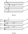
- Fig. 5a shows an example of how the electric arc A may travel through the splitter plates 7a-7c in case the non-magnetic layers 15 and the magnetic layer 13 of the splitter plates 7a-7c have been joined, or in the event of coating. Due to the repulsion of the arc at each level of the arc chute assembly 7 formed by the splitter plates 7a-7c, the blowing force may be directed in different direction, i.e. in which the arc moves in a plane parallel with the splitter plates 7a-7c as shown by the arrows, because the arc may travel through the splitter plates 7a-7c randomly.
- Fig. 5b shows an example of how the electric arc A may travel through the splitter plates 7a-7c in case the non-magnetic layers 15 and the magnetic layer 13 have not been joined or coated, i.e. if they are stacked in a detachable manner with a tight mounting between them.
- the non-magnetic sheets and the magnetic sheet are welded together in portions of the splitter plates 7a-7c closest to where the arc enters the arc chute assembly 7. This welding occurs initially when the arc enters the arc chute assembly 1, as indicated by references w, due to the heat. Because of these welds, the arc A will move in a more controlled manner through the splitter plates 7a-7c, in particular through the welds as indicated in Fig.
- the blowing force will always be directed in the same direction. Since the direction can be controlled, the dimensioning of the splitter plates 7a-7c may in the design stage be optimized based on the known direction in which the arc will move due to the blowing force.
- the electrical DC switching systems presented herein may for example be a circuit breaker, a contactor, or a current limiter, and may be utilised in DC applications, for example in low voltage (LV) applications or medium voltage (MV) applications.
- LV low voltage
- MV medium voltage
Landscapes
- Engineering & Computer Science (AREA)
- Power Engineering (AREA)
- Arc-Extinguishing Devices That Are Switches (AREA)
Priority Applications (5)
| Application Number | Priority Date | Filing Date | Title |
|---|---|---|---|
| EP16202187.7A EP3330992B1 (de) | 2016-12-05 | 2016-12-05 | Elektrisches gleichstromschaltsystem |
| RU2019120686A RU2714668C1 (ru) | 2016-12-05 | 2017-11-22 | Электрическая коммутационная система постоянного тока |
| CN201780074820.7A CN110024069B (zh) | 2016-12-05 | 2017-11-22 | 电气dc开关系统 |
| PCT/EP2017/080041 WO2018104054A1 (en) | 2016-12-05 | 2017-11-22 | Electrical dc switching system |
| US16/466,955 US10665404B2 (en) | 2016-12-05 | 2017-11-22 | Electrical DC switching system |
Applications Claiming Priority (1)
| Application Number | Priority Date | Filing Date | Title |
|---|---|---|---|
| EP16202187.7A EP3330992B1 (de) | 2016-12-05 | 2016-12-05 | Elektrisches gleichstromschaltsystem |
Publications (2)
| Publication Number | Publication Date |
|---|---|
| EP3330992A1 true EP3330992A1 (de) | 2018-06-06 |
| EP3330992B1 EP3330992B1 (de) | 2019-11-20 |
Family
ID=57482319
Family Applications (1)
| Application Number | Title | Priority Date | Filing Date |
|---|---|---|---|
| EP16202187.7A Active EP3330992B1 (de) | 2016-12-05 | 2016-12-05 | Elektrisches gleichstromschaltsystem |
Country Status (5)
| Country | Link |
|---|---|
| US (1) | US10665404B2 (de) |
| EP (1) | EP3330992B1 (de) |
| CN (1) | CN110024069B (de) |
| RU (1) | RU2714668C1 (de) |
| WO (1) | WO2018104054A1 (de) |
Cited By (1)
| Publication number | Priority date | Publication date | Assignee | Title |
|---|---|---|---|---|
| EP4273900A1 (de) * | 2022-05-05 | 2023-11-08 | Abb Schweiz Ag | Elektrische schaltvorrichtung |
Families Citing this family (2)
| Publication number | Priority date | Publication date | Assignee | Title |
|---|---|---|---|---|
| EP4195230A1 (de) * | 2021-12-10 | 2023-06-14 | Abb Schweiz Ag | Kompakter kontaktor |
| US11837865B2 (en) * | 2021-12-21 | 2023-12-05 | Abb S.P.A. | Hybrid circuit breakers |
Citations (8)
| Publication number | Priority date | Publication date | Assignee | Title |
|---|---|---|---|---|
| CH521017A (de) * | 1970-06-13 | 1972-03-31 | Siemens Ag | Elektrischer Schalter |
| DE2362089A1 (de) * | 1973-12-14 | 1975-06-26 | Degussa | Loeschbleche fuer elektrische schalter |
| DE3044153A1 (de) * | 1980-11-24 | 1982-06-24 | Siemens Ag | Lichtbogen-loeschkammer |
| EP0092207A2 (de) * | 1982-04-19 | 1983-10-26 | Kabushiki Kaisha Toshiba | Gleichstromleistungsschalter |
| DE69618105T2 (de) * | 1995-08-08 | 2002-07-18 | Electric Power Development Co., Ltd. | Gleichstromleistungsschalter |
| WO2012076603A1 (de) * | 2010-12-07 | 2012-06-14 | Eaton Industries Gmbh | Schalter mit loeschkammer |
| WO2013152799A1 (en) * | 2012-04-13 | 2013-10-17 | Abb Technology Ag | Passive resonance dc circuit breaker |
| WO2016131949A1 (en) | 2015-02-20 | 2016-08-25 | Abb Technology Ltd | Switching system for breaking a current and method of performing a current breaking operation |
Family Cites Families (9)
| Publication number | Priority date | Publication date | Assignee | Title |
|---|---|---|---|---|
| SU586510A1 (ru) | 1976-09-10 | 1977-12-30 | Bakhtinov Vasilij P | Устройство дл управлени синхронизированным выключателем переменного тока |
| US4443673A (en) | 1981-12-14 | 1984-04-17 | General Electric Company | Variable aspect arc chute |
| US4485283A (en) | 1982-08-27 | 1984-11-27 | General Electric Company | Current limiter unit |
| JP3114328B2 (ja) * | 1992-02-20 | 2000-12-04 | 株式会社日立製作所 | 直流遮断器 |
| US5866864A (en) | 1997-07-14 | 1999-02-02 | Eaton Corporation | Electric current switching apparatus with arc spinning extinguisher |
| DE102008024420A1 (de) | 2008-05-16 | 2009-11-19 | Siemens Aktiengesellschaft | Verfahren zur Bestimmung eines Schaltzeitpunktes eines elektrischen Schaltgerätes |
| RU2451360C1 (ru) | 2008-06-10 | 2012-05-20 | Абб Текнолоджи Аг | Выключатель постоянного тока |
| DE202009004198U1 (de) * | 2009-03-25 | 2010-08-12 | Ellenberger & Poensgen Gmbh | Trennschalter zur galvanischen Gleichstromunterbrechung |
| WO2011147458A1 (en) * | 2010-05-28 | 2011-12-01 | Abb Research Ltd | A dc switching device |
-
2016
- 2016-12-05 EP EP16202187.7A patent/EP3330992B1/de active Active
-
2017
- 2017-11-22 RU RU2019120686A patent/RU2714668C1/ru active
- 2017-11-22 CN CN201780074820.7A patent/CN110024069B/zh active Active
- 2017-11-22 WO PCT/EP2017/080041 patent/WO2018104054A1/en active Application Filing
- 2017-11-22 US US16/466,955 patent/US10665404B2/en active Active
Patent Citations (8)
| Publication number | Priority date | Publication date | Assignee | Title |
|---|---|---|---|---|
| CH521017A (de) * | 1970-06-13 | 1972-03-31 | Siemens Ag | Elektrischer Schalter |
| DE2362089A1 (de) * | 1973-12-14 | 1975-06-26 | Degussa | Loeschbleche fuer elektrische schalter |
| DE3044153A1 (de) * | 1980-11-24 | 1982-06-24 | Siemens Ag | Lichtbogen-loeschkammer |
| EP0092207A2 (de) * | 1982-04-19 | 1983-10-26 | Kabushiki Kaisha Toshiba | Gleichstromleistungsschalter |
| DE69618105T2 (de) * | 1995-08-08 | 2002-07-18 | Electric Power Development Co., Ltd. | Gleichstromleistungsschalter |
| WO2012076603A1 (de) * | 2010-12-07 | 2012-06-14 | Eaton Industries Gmbh | Schalter mit loeschkammer |
| WO2013152799A1 (en) * | 2012-04-13 | 2013-10-17 | Abb Technology Ag | Passive resonance dc circuit breaker |
| WO2016131949A1 (en) | 2015-02-20 | 2016-08-25 | Abb Technology Ltd | Switching system for breaking a current and method of performing a current breaking operation |
Non-Patent Citations (1)
| Title |
|---|
| ADIL ERK ET AL: "Anwendungen des Wechslstrom-Löschprinzip bei Gleichstromausschaltung", GRUNDLAGEN DER SCHALTGERÄTETECHNIK, 31 December 1975 (1975-12-31), pages 20 - 21, XP055371240, ISBN: 978-3-540-06075-8, Retrieved from the Internet <URL:none> [retrieved on 20170510] * |
Cited By (1)
| Publication number | Priority date | Publication date | Assignee | Title |
|---|---|---|---|---|
| EP4273900A1 (de) * | 2022-05-05 | 2023-11-08 | Abb Schweiz Ag | Elektrische schaltvorrichtung |
Also Published As
| Publication number | Publication date |
|---|---|
| CN110024069A (zh) | 2019-07-16 |
| US10665404B2 (en) | 2020-05-26 |
| EP3330992B1 (de) | 2019-11-20 |
| US20190348238A1 (en) | 2019-11-14 |
| WO2018104054A1 (en) | 2018-06-14 |
| RU2714668C1 (ru) | 2020-02-19 |
| CN110024069B (zh) | 2020-10-27 |
Similar Documents
| Publication | Publication Date | Title |
|---|---|---|
| US10665404B2 (en) | Electrical DC switching system | |
| US20180041021A1 (en) | Switching System For Breaking A Current And Method Of Performing A Current Breaking Operation | |
| JP5041311B2 (ja) | 直流および交流駆動用接触器 | |
| US9691560B2 (en) | Single- or multi-pole switching device, in particular for DC applications | |
| KR101758923B1 (ko) | 플라즈마 생성 장치 | |
| EP3631831B1 (de) | Elektrisches schaltsystem für gleichstrom | |
| CN107533926B (zh) | 旁路开关、提供导电路径的方法和功率系统 | |
| CA2942658C (en) | Knife blade switch contact with high resistance portion | |
| US11232918B2 (en) | Switching device for conducting and interrupting electrical currents | |
| US11087940B2 (en) | Electrical interruption device | |
| EP2597664A1 (de) | Schalter für Gleichstrombetrieb mit mindestens einer Schaltkammer | |
| US11621135B2 (en) | Armature for electromagnetic actuator, an electromagnetic actuator, a switch device and a method for manufacturing an armature | |
| US9087654B2 (en) | Arc chute arrangement for arc quenching in electrical switching device | |
| JP7043647B2 (ja) | 限流装置 | |
| US11335524B2 (en) | Electrical switching system | |
| Yu et al. | An approach for minimum percussion welding in closing operation of a 126-kV vacuum circuit breaker | |
| JP6859989B2 (ja) | 電流制御電極付遮断器 | |
| Fridman et al. | Application of coaxial cable lengths for capacitor protection in large capacitors banks | |
| Hahne et al. | High Current, High Voltage Bus Design | |
| JPH05316759A (ja) | エネルギー発生装置 |
Legal Events
| Date | Code | Title | Description |
|---|---|---|---|
| PUAI | Public reference made under article 153(3) epc to a published international application that has entered the european phase |
Free format text: ORIGINAL CODE: 0009012 |
|
| STAA | Information on the status of an ep patent application or granted ep patent |
Free format text: STATUS: THE APPLICATION HAS BEEN PUBLISHED |
|
| AK | Designated contracting states |
Kind code of ref document: A1 Designated state(s): AL AT BE BG CH CY CZ DE DK EE ES FI FR GB GR HR HU IE IS IT LI LT LU LV MC MK MT NL NO PL PT RO RS SE SI SK SM TR |
|
| AX | Request for extension of the european patent |
Extension state: BA ME |
|
| STAA | Information on the status of an ep patent application or granted ep patent |
Free format text: STATUS: REQUEST FOR EXAMINATION WAS MADE |
|
| 17P | Request for examination filed |
Effective date: 20181206 |
|
| RBV | Designated contracting states (corrected) |
Designated state(s): AL AT BE BG CH CY CZ DE DK EE ES FI FR GB GR HR HU IE IS IT LI LT LU LV MC MK MT NL NO PL PT RO RS SE SI SK SM TR |
|
| GRAP | Despatch of communication of intention to grant a patent |
Free format text: ORIGINAL CODE: EPIDOSNIGR1 |
|
| STAA | Information on the status of an ep patent application or granted ep patent |
Free format text: STATUS: GRANT OF PATENT IS INTENDED |
|
| INTG | Intention to grant announced |
Effective date: 20190621 |
|
| GRAS | Grant fee paid |
Free format text: ORIGINAL CODE: EPIDOSNIGR3 |
|
| GRAA | (expected) grant |
Free format text: ORIGINAL CODE: 0009210 |
|
| STAA | Information on the status of an ep patent application or granted ep patent |
Free format text: STATUS: THE PATENT HAS BEEN GRANTED |
|
| AK | Designated contracting states |
Kind code of ref document: B1 Designated state(s): AL AT BE BG CH CY CZ DE DK EE ES FI FR GB GR HR HU IE IS IT LI LT LU LV MC MK MT NL NO PL PT RO RS SE SI SK SM TR |
|
| REG | Reference to a national code |
Ref country code: GB Ref legal event code: FG4D |
|
| REG | Reference to a national code |
Ref country code: CH Ref legal event code: EP |
|
| REG | Reference to a national code |
Ref country code: IE Ref legal event code: FG4D |
|
| REG | Reference to a national code |
Ref country code: DE Ref legal event code: R096 Ref document number: 602016024596 Country of ref document: DE |
|
| REG | Reference to a national code |
Ref country code: AT Ref legal event code: REF Ref document number: 1205132 Country of ref document: AT Kind code of ref document: T Effective date: 20191215 |
|
| REG | Reference to a national code |
Ref country code: NL Ref legal event code: MP Effective date: 20191120 |
|
| REG | Reference to a national code |
Ref country code: LT Ref legal event code: MG4D |
|
| PG25 | Lapsed in a contracting state [announced via postgrant information from national office to epo] |
Ref country code: BG Free format text: LAPSE BECAUSE OF FAILURE TO SUBMIT A TRANSLATION OF THE DESCRIPTION OR TO PAY THE FEE WITHIN THE PRESCRIBED TIME-LIMIT Effective date: 20200220 Ref country code: NO Free format text: LAPSE BECAUSE OF FAILURE TO SUBMIT A TRANSLATION OF THE DESCRIPTION OR TO PAY THE FEE WITHIN THE PRESCRIBED TIME-LIMIT Effective date: 20200220 Ref country code: FI Free format text: LAPSE BECAUSE OF FAILURE TO SUBMIT A TRANSLATION OF THE DESCRIPTION OR TO PAY THE FEE WITHIN THE PRESCRIBED TIME-LIMIT Effective date: 20191120 Ref country code: LV Free format text: LAPSE BECAUSE OF FAILURE TO SUBMIT A TRANSLATION OF THE DESCRIPTION OR TO PAY THE FEE WITHIN THE PRESCRIBED TIME-LIMIT Effective date: 20191120 Ref country code: SE Free format text: LAPSE BECAUSE OF FAILURE TO SUBMIT A TRANSLATION OF THE DESCRIPTION OR TO PAY THE FEE WITHIN THE PRESCRIBED TIME-LIMIT Effective date: 20191120 Ref country code: NL Free format text: LAPSE BECAUSE OF FAILURE TO SUBMIT A TRANSLATION OF THE DESCRIPTION OR TO PAY THE FEE WITHIN THE PRESCRIBED TIME-LIMIT Effective date: 20191120 Ref country code: LT Free format text: LAPSE BECAUSE OF FAILURE TO SUBMIT A TRANSLATION OF THE DESCRIPTION OR TO PAY THE FEE WITHIN THE PRESCRIBED TIME-LIMIT Effective date: 20191120 Ref country code: GR Free format text: LAPSE BECAUSE OF FAILURE TO SUBMIT A TRANSLATION OF THE DESCRIPTION OR TO PAY THE FEE WITHIN THE PRESCRIBED TIME-LIMIT Effective date: 20200221 |
|
| PG25 | Lapsed in a contracting state [announced via postgrant information from national office to epo] |
Ref country code: HR Free format text: LAPSE BECAUSE OF FAILURE TO SUBMIT A TRANSLATION OF THE DESCRIPTION OR TO PAY THE FEE WITHIN THE PRESCRIBED TIME-LIMIT Effective date: 20191120 Ref country code: IS Free format text: LAPSE BECAUSE OF FAILURE TO SUBMIT A TRANSLATION OF THE DESCRIPTION OR TO PAY THE FEE WITHIN THE PRESCRIBED TIME-LIMIT Effective date: 20200320 Ref country code: RS Free format text: LAPSE BECAUSE OF FAILURE TO SUBMIT A TRANSLATION OF THE DESCRIPTION OR TO PAY THE FEE WITHIN THE PRESCRIBED TIME-LIMIT Effective date: 20191120 |
|
| PG25 | Lapsed in a contracting state [announced via postgrant information from national office to epo] |
Ref country code: AL Free format text: LAPSE BECAUSE OF FAILURE TO SUBMIT A TRANSLATION OF THE DESCRIPTION OR TO PAY THE FEE WITHIN THE PRESCRIBED TIME-LIMIT Effective date: 20191120 |
|
| PG25 | Lapsed in a contracting state [announced via postgrant information from national office to epo] |
Ref country code: EE Free format text: LAPSE BECAUSE OF FAILURE TO SUBMIT A TRANSLATION OF THE DESCRIPTION OR TO PAY THE FEE WITHIN THE PRESCRIBED TIME-LIMIT Effective date: 20191120 Ref country code: DK Free format text: LAPSE BECAUSE OF FAILURE TO SUBMIT A TRANSLATION OF THE DESCRIPTION OR TO PAY THE FEE WITHIN THE PRESCRIBED TIME-LIMIT Effective date: 20191120 Ref country code: RO Free format text: LAPSE BECAUSE OF FAILURE TO SUBMIT A TRANSLATION OF THE DESCRIPTION OR TO PAY THE FEE WITHIN THE PRESCRIBED TIME-LIMIT Effective date: 20191120 Ref country code: PT Free format text: LAPSE BECAUSE OF FAILURE TO SUBMIT A TRANSLATION OF THE DESCRIPTION OR TO PAY THE FEE WITHIN THE PRESCRIBED TIME-LIMIT Effective date: 20200412 Ref country code: CZ Free format text: LAPSE BECAUSE OF FAILURE TO SUBMIT A TRANSLATION OF THE DESCRIPTION OR TO PAY THE FEE WITHIN THE PRESCRIBED TIME-LIMIT Effective date: 20191120 Ref country code: ES Free format text: LAPSE BECAUSE OF FAILURE TO SUBMIT A TRANSLATION OF THE DESCRIPTION OR TO PAY THE FEE WITHIN THE PRESCRIBED TIME-LIMIT Effective date: 20191120 |
|
| REG | Reference to a national code |
Ref country code: CH Ref legal event code: PL |
|
| REG | Reference to a national code |
Ref country code: AT Ref legal event code: MK05 Ref document number: 1205132 Country of ref document: AT Kind code of ref document: T Effective date: 20191120 |
|
| REG | Reference to a national code |
Ref country code: DE Ref legal event code: R097 Ref document number: 602016024596 Country of ref document: DE |
|
| REG | Reference to a national code |
Ref country code: BE Ref legal event code: MM Effective date: 20191231 |
|
| PG25 | Lapsed in a contracting state [announced via postgrant information from national office to epo] |
Ref country code: SM Free format text: LAPSE BECAUSE OF FAILURE TO SUBMIT A TRANSLATION OF THE DESCRIPTION OR TO PAY THE FEE WITHIN THE PRESCRIBED TIME-LIMIT Effective date: 20191120 Ref country code: MC Free format text: LAPSE BECAUSE OF FAILURE TO SUBMIT A TRANSLATION OF THE DESCRIPTION OR TO PAY THE FEE WITHIN THE PRESCRIBED TIME-LIMIT Effective date: 20191120 Ref country code: SK Free format text: LAPSE BECAUSE OF FAILURE TO SUBMIT A TRANSLATION OF THE DESCRIPTION OR TO PAY THE FEE WITHIN THE PRESCRIBED TIME-LIMIT Effective date: 20191120 |
|
| PLBE | No opposition filed within time limit |
Free format text: ORIGINAL CODE: 0009261 |
|
| STAA | Information on the status of an ep patent application or granted ep patent |
Free format text: STATUS: NO OPPOSITION FILED WITHIN TIME LIMIT |
|
| 26N | No opposition filed |
Effective date: 20200821 |
|
| PG25 | Lapsed in a contracting state [announced via postgrant information from national office to epo] |
Ref country code: LU Free format text: LAPSE BECAUSE OF NON-PAYMENT OF DUE FEES Effective date: 20191205 Ref country code: IE Free format text: LAPSE BECAUSE OF NON-PAYMENT OF DUE FEES Effective date: 20191205 |
|
| PG25 | Lapsed in a contracting state [announced via postgrant information from national office to epo] |
Ref country code: CH Free format text: LAPSE BECAUSE OF NON-PAYMENT OF DUE FEES Effective date: 20191231 Ref country code: BE Free format text: LAPSE BECAUSE OF NON-PAYMENT OF DUE FEES Effective date: 20191231 Ref country code: LI Free format text: LAPSE BECAUSE OF NON-PAYMENT OF DUE FEES Effective date: 20191231 Ref country code: AT Free format text: LAPSE BECAUSE OF FAILURE TO SUBMIT A TRANSLATION OF THE DESCRIPTION OR TO PAY THE FEE WITHIN THE PRESCRIBED TIME-LIMIT Effective date: 20191120 Ref country code: PL Free format text: LAPSE BECAUSE OF FAILURE TO SUBMIT A TRANSLATION OF THE DESCRIPTION OR TO PAY THE FEE WITHIN THE PRESCRIBED TIME-LIMIT Effective date: 20191120 Ref country code: SI Free format text: LAPSE BECAUSE OF FAILURE TO SUBMIT A TRANSLATION OF THE DESCRIPTION OR TO PAY THE FEE WITHIN THE PRESCRIBED TIME-LIMIT Effective date: 20191120 |
|
| PG25 | Lapsed in a contracting state [announced via postgrant information from national office to epo] |
Ref country code: CY Free format text: LAPSE BECAUSE OF FAILURE TO SUBMIT A TRANSLATION OF THE DESCRIPTION OR TO PAY THE FEE WITHIN THE PRESCRIBED TIME-LIMIT Effective date: 20191120 |
|
| PG25 | Lapsed in a contracting state [announced via postgrant information from national office to epo] |
Ref country code: MT Free format text: LAPSE BECAUSE OF FAILURE TO SUBMIT A TRANSLATION OF THE DESCRIPTION OR TO PAY THE FEE WITHIN THE PRESCRIBED TIME-LIMIT Effective date: 20191120 Ref country code: HU Free format text: LAPSE BECAUSE OF FAILURE TO SUBMIT A TRANSLATION OF THE DESCRIPTION OR TO PAY THE FEE WITHIN THE PRESCRIBED TIME-LIMIT; INVALID AB INITIO Effective date: 20161205 |
|
| GBPC | Gb: european patent ceased through non-payment of renewal fee |
Effective date: 20201205 |
|
| PG25 | Lapsed in a contracting state [announced via postgrant information from national office to epo] |
Ref country code: GB Free format text: LAPSE BECAUSE OF NON-PAYMENT OF DUE FEES Effective date: 20201205 |
|
| PG25 | Lapsed in a contracting state [announced via postgrant information from national office to epo] |
Ref country code: TR Free format text: LAPSE BECAUSE OF FAILURE TO SUBMIT A TRANSLATION OF THE DESCRIPTION OR TO PAY THE FEE WITHIN THE PRESCRIBED TIME-LIMIT Effective date: 20191120 |
|
| PG25 | Lapsed in a contracting state [announced via postgrant information from national office to epo] |
Ref country code: MK Free format text: LAPSE BECAUSE OF FAILURE TO SUBMIT A TRANSLATION OF THE DESCRIPTION OR TO PAY THE FEE WITHIN THE PRESCRIBED TIME-LIMIT Effective date: 20191120 |
|
| PGFP | Annual fee paid to national office [announced via postgrant information from national office to epo] |
Ref country code: IT Payment date: 20231228 Year of fee payment: 8 Ref country code: FR Payment date: 20231222 Year of fee payment: 8 Ref country code: DE Payment date: 20231214 Year of fee payment: 8 |