EP3330587B1 - Rohrverbindung mit einer ringdichtung zur verwendung in einer ringsicke eines aussenrohres zum abdichten des aussenrohres - Google Patents
Rohrverbindung mit einer ringdichtung zur verwendung in einer ringsicke eines aussenrohres zum abdichten des aussenrohres Download PDFInfo
- Publication number
- EP3330587B1 EP3330587B1 EP17202257.6A EP17202257A EP3330587B1 EP 3330587 B1 EP3330587 B1 EP 3330587B1 EP 17202257 A EP17202257 A EP 17202257A EP 3330587 B1 EP3330587 B1 EP 3330587B1
- Authority
- EP
- European Patent Office
- Prior art keywords
- pipe
- abutment
- sealing lip
- sealing
- joint according
- Prior art date
- Legal status (The legal status is an assumption and is not a legal conclusion. Google has not performed a legal analysis and makes no representation as to the accuracy of the status listed.)
- Active
Links
- 238000007789 sealing Methods 0.000 title claims description 84
- 238000003780 insertion Methods 0.000 claims description 24
- 230000037431 insertion Effects 0.000 claims description 24
- 239000011324 bead Substances 0.000 description 41
- 239000000463 material Substances 0.000 description 7
- 238000009825 accumulation Methods 0.000 description 5
- 238000005096 rolling process Methods 0.000 description 4
- 238000000926 separation method Methods 0.000 description 4
- 238000004140 cleaning Methods 0.000 description 2
- 239000002184 metal Substances 0.000 description 2
- 230000007704 transition Effects 0.000 description 2
- 238000010586 diagram Methods 0.000 description 1
- 238000000034 method Methods 0.000 description 1
- 230000008092 positive effect Effects 0.000 description 1
- 230000002787 reinforcement Effects 0.000 description 1
- 230000003014 reinforcing effect Effects 0.000 description 1
- 230000000630 rising effect Effects 0.000 description 1
- 239000003566 sealing material Substances 0.000 description 1
Images

Classifications
-
- F—MECHANICAL ENGINEERING; LIGHTING; HEATING; WEAPONS; BLASTING
- F16—ENGINEERING ELEMENTS AND UNITS; GENERAL MEASURES FOR PRODUCING AND MAINTAINING EFFECTIVE FUNCTIONING OF MACHINES OR INSTALLATIONS; THERMAL INSULATION IN GENERAL
- F16L—PIPES; JOINTS OR FITTINGS FOR PIPES; SUPPORTS FOR PIPES, CABLES OR PROTECTIVE TUBING; MEANS FOR THERMAL INSULATION IN GENERAL
- F16L21/00—Joints with sleeve or socket
- F16L21/02—Joints with sleeve or socket with elastic sealing rings between pipe and sleeve or between pipe and socket, e.g. with rolling or other prefabricated profiled rings
- F16L21/03—Joints with sleeve or socket with elastic sealing rings between pipe and sleeve or between pipe and socket, e.g. with rolling or other prefabricated profiled rings placed in the socket before connection
-
- F—MECHANICAL ENGINEERING; LIGHTING; HEATING; WEAPONS; BLASTING
- F16—ENGINEERING ELEMENTS AND UNITS; GENERAL MEASURES FOR PRODUCING AND MAINTAINING EFFECTIVE FUNCTIONING OF MACHINES OR INSTALLATIONS; THERMAL INSULATION IN GENERAL
- F16L—PIPES; JOINTS OR FITTINGS FOR PIPES; SUPPORTS FOR PIPES, CABLES OR PROTECTIVE TUBING; MEANS FOR THERMAL INSULATION IN GENERAL
- F16L17/00—Joints with packing adapted to sealing by fluid pressure
- F16L17/02—Joints with packing adapted to sealing by fluid pressure with sealing rings arranged between outer surface of pipe and inner surface of sleeve or socket
- F16L17/025—Joints with packing adapted to sealing by fluid pressure with sealing rings arranged between outer surface of pipe and inner surface of sleeve or socket the sealing rings having radially directed ribs
Definitions
- the invention relates to a pipe connection with an outer tube with an annular bead and an inner tube which is partially inserted into the outer tube, and which overlap in the area of the annular bead, with the features of the preamble of claim 1. Furthermore, the invention relates to an annular seal for use in a such pipe connection.
- FIG DE 20 2014 004 538 U1 A generic pipe connection with an outer tube with an annular bead and an annular seal for use in the annular bead of the outer tube for sealing the outer tube against an inner tube to be inserted into the outer tube is shown in FIG DE 20 2014 004 538 U1 known.
- the ring seal is designed such that a cleaning lip is arranged on the base body in front of the sealing lip, ie, viewed in cross section, on the side from which the inner tube is inserted, which also protrudes beyond the base body and projects into the annular gap and thereby has a cleaning function.
- annular seal for a push-in joint is known.
- the ring seal has a base body and a sealing wedge.
- the peculiarity of this seal consists in a cavity that allows the sealing wedge to be moved relative to the base body.
- a connector for metal pipes is in the EP 2 366 933 A1 described.
- the connector has an at least three-stage seal with an earring, a clamping ring and a lip seal.
- the lip seal is formed in a circumferential recess with a trapezoidal cross section, which widens in the direction of insertion.
- the lip seal is substantially V-shaped in cross-section with an inner lip, the inner lip having a step.
- a pipe fitting with a combination of an O-ring seal section and a lip seal section is shown in US Pat EP 1 840 436 A1 known.
- a cone part is screwed into a housing to make the connection.
- the DE 20 2004 016 334 U1 describes an O-ring for insertion in a circumferential groove of a pipe.
- the round sealing ring has a sealing ring and a support ring.
- the base body of the seal is provided with a support ring made of a significantly harder material, in particular a rigid plastic, which supports the actual seal ring made of the softer rubber material.
- an inwardly open groove or ring bead is provided, into which a circumferential ring seal is inserted, which seals the annular gap between the two pipe ends.
- the ring seal has a base body which, in the assembled state, is arranged essentially within the ring bead and also has a radially circumferential sealing lip which, in the installed state, projects beyond the ring bead.
- the second tube with the smaller diameter is inserted into the first tube with the larger diameter and runs onto the radially circumferential sealing lip, which is bent and pressed in the process and thereby comes into sealing contact with the inserted inner tube.
- the invention has for its object to provide a pipe connection with an outer tube with an annular bead and an annular seal for use in the annular bead of the outer tube of the type mentioned, in which a particularly reliable fit of the ring seal is possible.
- annular seal which seals an annular gap between the outer tube and the inner tube is arranged in the annular bead only from a base body, which can be positioned essentially in the ring bead, and has a radially circumferential sealing lip which extends from the base body and which, in the installed state, projects beyond the ring bead and is determined for the density in contact with the inner tube.
- the base body of the ring seal has a cross section, on the side from which the inner tube is inserted, an abutment directed toward the inner tube, the abutment having an upwardly convex profile, that is to say radially inwardly convex, and wherein convex-shaped profile in cross-section is separated from the sealing lip by a change in slope, namely a change in sign of the slope, in cross-section.
- the highest point of the abutment is in the built-in state, which is not acted upon by the inner tube, within the ring bead. In contrast, the highest point of the abutment is pressed against the inner tube in the installed state, which is acted upon by the inner tube.
- the abutment viewed in cross section, has a second convex curvature on the side from which the inner tube is inserted, which is aligned with the side wall of the ring bead, the convex curvature shape being formed up to a foot of the basic body and between the basic body and a free space remains on the wall of the ring bead.
- the separation is to be understood as a spatial delimitation.
- the abutment prevents the ring seal from twisting or screwing in.
- One speaks here of a "rolling" of the ring seal which is prevented by the accumulation of material in the convex profile of the abutment.
- the ring seal is caused to rotate at the latest when the inner tube is pushed in and meets the sealing lip. This is thus suppressed by the ring seal according to the invention with the abutment, since the abutment lies against the inner tube and prevents the ring seal from rolling.
- the abutment and sealing lip are separated by changing the pitch in the profile.
- the profile in the area of the abutment only rises, i.e. has a positive slope, after exceeding the peak of the abutment it has a negative slope and then passes through a low point and has a positive slope again in the area of the rising flank of the sealing lip .
- a sign change of the slope takes place in the area of this low point.
- This represents the separation between the abutment and the sealing lip.
- This is preferably an inconsistent change in pitch, that is to say a sharp bend.
- there is also a constant change of incline that is to say in the form of a curve.
- the highest point of the abutment is in the installed but unloaded state according to the invention within the ring bead, so that it is ensured that the inner tube slides over the abutment during insertion and the abutment is only pressed against the inner tube after the inner tube has hit the sealing lip.
- the abutment could also protrude minimally from the ring bead, since there is naturally a certain amount of play between the inner tube and the outer tube.
- the abutment has a convex curvature, seen in profile, on the side from which the inner tube is inserted.
- it is a second convex curvature, namely, in addition to the first, upward curvature, a second convex curvature is provided which is oriented forward on the side wall of the ring bead.
- This is especially formed in the lower area, in particular in the lower half.
- this convex curvature is preferably designed in such a way that the most protruding point of the curvature lies in the upper region, but the convex curvature shape is continuous up to a foot of the base body.
- the front side preferably exclusively faces within the ring bead a continuous convex curvature, which is directed to the side wall of the ring bead.
- an additional sealing tip is arranged between the abutment and the sealing lip.
- This sealing tip is lower than the sealing lip, but higher than the abutment, so it projects beyond the base body and comes into contact with the inner tube when the inner tube is inserted.
- the sealing tip preferably has a first flank on the abutment side and a second flank on the side of the sealing lip, the first flank being longer than the second flank.
- the sealing lip has a special configuration.
- the tip of the sealing lip is preferably asymmetrical with respect to an angle bisector, namely has a bevel on the back.
- the sealing lip and the bevel are dimensioned in such a way that when the sealing lip is folded over, this bevel lies in the area of the upper edge of the ring bead and is better introduced there. This avoids so-called socket crushers.
- the seal slips better into the ring bead.
- the sealing lip preferably has a back support on the side opposite the insertion side of the inner tube. In the transition area between the sealing lip and the base body, a positive material accumulation is provided on the back. In particular, there is no undercut here, as is often the case in the prior art.
- This back support is preferably formed over more than a third of the free height of the sealing lip.
- the free height of the sealing lip is calculated on this rear side of the sealing lip from the top of the base body to the tip of the sealing lip.
- the ring seal is designed such that the center point of the sealing tip, relative to the total width of the ring seal from 1, is positioned at approximately 0.35 to 0.45.
- the center point of the sealing tip is particularly preferably positioned at approximately 0.4 or 0.38 to 0.42.
- the center point of the sealing lip is positioned at about 0.7 to 0.8, preferably at about 0.73 to 0.77, based on the overall width of the ring seal of 1.
- the abutment is located at the beginning of the ring seal and, unlike the sealing tip and the sealing lip, cannot be fixed to a central point, but is in its total width at about 0 to 0.2 of the ring seal if it is standardized to 1.
- Another aspect of the invention relates to a pipe connection with an outer tube with an annular bead and an inner tube which is partially inserted into the outer tube and which overlap in the area of the annular bead, an annular seal being arranged in the annular bead which has an annular gap between the outer tube and the inner tube seals, whereby the outer tube with the ring seal corresponds to that described above.
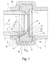
- annular seal 1 is shown in an outer tube 2, the outer tube 2 having in its end region a circumferential annular bead 3 in which the annular seal 1 is arranged.
- the outer tube 2 becomes narrower and there has a region tapered in comparison to the outer tube 2 and forms an inner tube 4. This would correspond to the pipe protruding from the left here.
- This inner tube 4 is inserted into the outer tube 2 in the insertion direction 10, which is shown by the corresponding arrow.
- this inner tube 4 has a front inclined area or a chamfer 30, which is intended to facilitate insertion. In order to enable insertion at all, certain size tolerances are provided, so that an annular gap 9 remains between the outer tube 2 and the inner tube 4.
- a circumferential ring seal 1 is provided, which is inserted into the ring bead 3.
- the ring seal 1 essentially has a base body 5, which is located within the ring bead 3 or can be arranged therein.
- a sealing lip 6 rises from the base body 5, which protrudes beyond the ring bead 3 and is then gripped by the inner tube 4 and ultimately brings about the sealing.
- an abutment 7 is provided here according to the invention with a positive material accumulation, in particular a convex profile 8 directed upwards, that is to say in the direction of the inner tube 4 to be inserted.
- This convex profile 8 is first seen from the insertion direction 10, when considering generally the contour or the profile 16 of the ring seal 1, initially with a positive slope 11 which extends to the highest point 14 of the convex profile 8 of the abutment 7. Thereafter, the profile 16 drops and there is a negative slope 12. At point 13 there is an incline change to the then positive incline 11 of the next section.
- this separation or delimitation is formed by an inconsistent change of slope in point 13.
- the sealing lip 6 is supplemented by an additional sealing tip 17, which also protrudes beyond the ring bead 3 and is captured by the inner tube 4 when inserted.
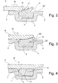
- the sealing tip 17 has a first flank 18 and a second flank 19, the first flank 18 being longer than the second flank 19.
- the sealing tip 17 is overall substantially lower than the sealing lip 6. In the transition between the sealing tip 17 and the sealing lip 6 there is also a lowest point is provided, which adjoins the second flank 19 with a negative slope, before a positive flank to the sealing lip 6 follows again.
- the terms positive increase and negative increase refer to the insertion direction 10 in accordance with the figure.
- the sealing lip 6 itself is asymmetrical, in particular with respect to an bisector 20 in the sealing lip 6.
- a back support 23 is provided, which can also be understood as a positive accumulation of material and extends over approximately a third of the free height of the sealing lip 6.
- the free height of the sealing lip 6 is understood to mean the distance from the support area 29 on the upper side of the base body 5 to the tip of the sealing lip 6.
- the ring seal 1 has four feet 26 with three recesses 27 arranged between them.
- the lower area of the ring seal 1 here means the area which is circumferential in the ring bead 3 and is directed outwards and is in the drawing below. When installed, this is the outward-facing area of the Ring seal 1, which is inserted in the circumferential ring bead 3. A free space 28 remains in the ring bead 3, seen on the insertion side, which is delimited by the ring seal 1. In this region on the insertion side, the ring seal 1 also has a convex profile 15, which extends continuously to the feet 26.
- FIG 5 a cross section through the ring seal 1 is shown in a partial perspective view. The same parts are identified by the same reference symbols.
- the width 25 of the ring seal 1 is also shown.
- a scale from 0 to 1 is plotted, which is assigned to the width of the ring seal 1.
- the abutment 7 extends in the insert-side range from 0 to 0.2.
- the sealing tip 17 is in particular with its pointed area at a width between 0.35 and 0.45.
- the sealing lip 6 is in the range between 0.7 and 0.8. In particular, the tip of the sealing lip 6 is located there.
- the contact area 29 lies in the range 0.8 to 1.
- the convex profile 15 extends in a range from 0 to 0.2.
- the first foot 26 is therefore only arranged in the range between 0.2 and 1, in particular in the range between 0.25 and 1.
- the free height 24 is also shown here, which extends from the support area 29 to the tip of the sealing lip 6.
- the Back support 23 extends here preferably over more than a third of this free height 24.
Landscapes
- Engineering & Computer Science (AREA)
- General Engineering & Computer Science (AREA)
- Mechanical Engineering (AREA)
- Physics & Mathematics (AREA)
- Fluid Mechanics (AREA)
- Joints With Sleeves (AREA)
- Joints With Pressure Members (AREA)
- Gasket Seals (AREA)
Priority Applications (3)
| Application Number | Priority Date | Filing Date | Title |
|---|---|---|---|
| RS20201179A RS60912B1 (sr) | 2016-11-30 | 2017-11-17 | Cevni spoj sa prstenastom zaptivkom za primenu u prstenastom rubu spoljašnje cevi za zaptivanje spoljašnje cevi |
| PL17202257T PL3330587T3 (pl) | 2016-11-30 | 2017-11-17 | Połączenie rurowe z uszczelką pierścieniową do stosowania w rowku pierścieniowym rury zewnętrznej do uszczelniania rury zewnętrznej |
| HRP20201558TT HRP20201558T1 (hr) | 2016-11-30 | 2020-09-30 | Priključak cijevi s prstenastom brtvom za upotrebu u utoru vanjske cijevi za brtvljenje vanjske cijevi |
Applications Claiming Priority (1)
| Application Number | Priority Date | Filing Date | Title |
|---|---|---|---|
| DE102016123157.6A DE102016123157A1 (de) | 2016-11-30 | 2016-11-30 | Ringdichtung zur Verwendung in einer Ringsicke eines Außenrohres zum Abdichten des Außenrohres |
Publications (2)
| Publication Number | Publication Date |
|---|---|
| EP3330587A1 EP3330587A1 (de) | 2018-06-06 |
| EP3330587B1 true EP3330587B1 (de) | 2020-07-01 |
Family
ID=60387896
Family Applications (1)
| Application Number | Title | Priority Date | Filing Date |
|---|---|---|---|
| EP17202257.6A Active EP3330587B1 (de) | 2016-11-30 | 2017-11-17 | Rohrverbindung mit einer ringdichtung zur verwendung in einer ringsicke eines aussenrohres zum abdichten des aussenrohres |
Country Status (6)
| Country | Link |
|---|---|
| EP (1) | EP3330587B1 (es) |
| DE (1) | DE102016123157A1 (es) |
| ES (1) | ES2819674T3 (es) |
| HR (1) | HRP20201558T1 (es) |
| PL (1) | PL3330587T3 (es) |
| RS (1) | RS60912B1 (es) |
Families Citing this family (1)
| Publication number | Priority date | Publication date | Assignee | Title |
|---|---|---|---|---|
| JP6818303B2 (ja) * | 2018-09-12 | 2021-01-20 | 内山工業株式会社 | ガスケット |
Family Cites Families (10)
| Publication number | Priority date | Publication date | Assignee | Title |
|---|---|---|---|---|
| US3879067A (en) * | 1971-11-22 | 1975-04-22 | Price Brothers Co | Pipe joint |
| GB1574434A (en) * | 1977-01-11 | 1980-09-10 | Harrison G | Pipe coupling |
| CH633871A5 (fr) * | 1980-02-12 | 1982-12-31 | Plastag Sa | Joint d'etancheite pour le raccordement de tuyaux emboitables. |
| FR2647520B1 (fr) * | 1989-05-23 | 1994-09-23 | Pont A Mousson | Garniture d'etancheite, emboitement destine a recevoir ladite garniture et joint d'etancheite ainsi realise |
| DE202004016334U1 (de) * | 2004-10-21 | 2004-12-30 | M.D.S. Meyer Gmbh Dichtungssysteme | Runddichtring und Dichtungsring |
| EP1840436A1 (de) * | 2006-03-31 | 2007-10-03 | Hawle Armaturen GmbH | Kombinierte Dichtung für einen Rohrleitungsfitting |
| EP2366933A1 (de) * | 2010-03-03 | 2011-09-21 | R. Nussbaum AG | Anschlussstück für Metallrohre |
| DE102012019930A1 (de) * | 2012-10-11 | 2014-04-17 | M.O.L. Gummiverarbeitung Gmbh & Co. Kg | Dichtung für eine Steckmuffenverbindung von rohrförmigen Körpern |
| DE202014004538U1 (de) | 2014-05-28 | 2014-07-03 | Bode Gmbh | Ringdichtung mit Dichtlippe |
| DE202015103221U1 (de) * | 2015-06-18 | 2016-09-20 | Rehau Ag + Co | Rohr oder Rohrformteil |
-
2016
- 2016-11-30 DE DE102016123157.6A patent/DE102016123157A1/de not_active Withdrawn
-
2017
- 2017-11-17 EP EP17202257.6A patent/EP3330587B1/de active Active
- 2017-11-17 ES ES17202257T patent/ES2819674T3/es active Active
- 2017-11-17 RS RS20201179A patent/RS60912B1/sr unknown
- 2017-11-17 PL PL17202257T patent/PL3330587T3/pl unknown
-
2020
- 2020-09-30 HR HRP20201558TT patent/HRP20201558T1/hr unknown
Non-Patent Citations (1)
| Title |
|---|
| None * |
Also Published As
| Publication number | Publication date |
|---|---|
| PL3330587T3 (pl) | 2021-01-25 |
| ES2819674T3 (es) | 2021-04-19 |
| EP3330587A1 (de) | 2018-06-06 |
| RS60912B1 (sr) | 2020-11-30 |
| DE102016123157A1 (de) | 2018-05-30 |
| HRP20201558T1 (hr) | 2020-12-11 |
Similar Documents
| Publication | Publication Date | Title |
|---|---|---|
| EP0361630B1 (de) | Verfahren und Vorrichtung und Pressfitting zur Herstellung einer unlösbaren, dichten Verbindung von Rohren | |
| EP0528233B1 (de) | Klemmverschraubung mit Schraubhülse, Gegenhülse und Klemmeinsatz | |
| DE69701379T2 (de) | Rohrverbindung | |
| EP2757299B1 (de) | Rohrklemme | |
| EP2607764B1 (de) | Rohrklemme mit Anschlussstück | |
| EP3428498B1 (de) | Rohr, insbesondere kunststoffrohr für abwasserleitungen | |
| EP2463565B1 (de) | Rohrverbindungsanordnung | |
| DE10017221A1 (de) | Dichtungs-Ring für Verbindung zwischen Spitzende eines Wellrohres und Rohr-Muffe mit glatter Innenwand | |
| DE3903355A1 (de) | Anschlussarmatur fuer umfangsgerippte schlaeuche oder rohre | |
| DE2521930C2 (de) | Rohrverbindungsstück | |
| DE19614073B4 (de) | Trennungssichere Rohrverbindung | |
| EP2278204B1 (de) | Wellrohranschlussverschraubung | |
| EP3330587B1 (de) | Rohrverbindung mit einer ringdichtung zur verwendung in einer ringsicke eines aussenrohres zum abdichten des aussenrohres | |
| DE102010016972A1 (de) | Anschlussverbindung für ein Rohr | |
| EP2590752B1 (de) | Düsenkörper und gerätekopf eines reinigungsgeräts mit einem solchen düsenkörper | |
| DE102017210844A1 (de) | Presshülse | |
| DE102005000720C5 (de) | Rohrpresskupplung | |
| EP3167219B1 (de) | Anschlussteil | |
| DE10021306C2 (de) | Rohrkupplung | |
| EP2792915A1 (de) | Wellrohrverbindung | |
| DE29514822U1 (de) | Kupplungsteil | |
| DE102008032770B4 (de) | Hydraulik-Verbindervorrichtung | |
| AT515540B1 (de) | Anschlussteil für eine Rohrleitung | |
| EP3021027B1 (de) | Rohrverbindung | |
| DE112015006206T5 (de) | Verbindungsvorrichtung für gebördeltes rohr und verfahren dafür |
Legal Events
| Date | Code | Title | Description |
|---|---|---|---|
| PUAI | Public reference made under article 153(3) epc to a published international application that has entered the european phase |
Free format text: ORIGINAL CODE: 0009012 |
|
| STAA | Information on the status of an ep patent application or granted ep patent |
Free format text: STATUS: THE APPLICATION HAS BEEN PUBLISHED |
|
| AK | Designated contracting states |
Kind code of ref document: A1 Designated state(s): AL AT BE BG CH CY CZ DE DK EE ES FI FR GB GR HR HU IE IS IT LI LT LU LV MC MK MT NL NO PL PT RO RS SE SI SK SM TR |
|
| AX | Request for extension of the european patent |
Extension state: BA ME |
|
| STAA | Information on the status of an ep patent application or granted ep patent |
Free format text: STATUS: REQUEST FOR EXAMINATION WAS MADE |
|
| 17P | Request for examination filed |
Effective date: 20181206 |
|
| RBV | Designated contracting states (corrected) |
Designated state(s): AL AT BE BG CH CY CZ DE DK EE ES FI FR GB GR HR HU IE IS IT LI LT LU LV MC MK MT NL NO PL PT RO RS SE SI SK SM TR |
|
| STAA | Information on the status of an ep patent application or granted ep patent |
Free format text: STATUS: EXAMINATION IS IN PROGRESS |
|
| 17Q | First examination report despatched |
Effective date: 20190307 |
|
| GRAP | Despatch of communication of intention to grant a patent |
Free format text: ORIGINAL CODE: EPIDOSNIGR1 |
|
| STAA | Information on the status of an ep patent application or granted ep patent |
Free format text: STATUS: GRANT OF PATENT IS INTENDED |
|
| INTG | Intention to grant announced |
Effective date: 20200120 |
|
| GRAS | Grant fee paid |
Free format text: ORIGINAL CODE: EPIDOSNIGR3 |
|
| GRAA | (expected) grant |
Free format text: ORIGINAL CODE: 0009210 |
|
| STAA | Information on the status of an ep patent application or granted ep patent |
Free format text: STATUS: THE PATENT HAS BEEN GRANTED |
|
| AK | Designated contracting states |
Kind code of ref document: B1 Designated state(s): AL AT BE BG CH CY CZ DE DK EE ES FI FR GB GR HR HU IE IS IT LI LT LU LV MC MK MT NL NO PL PT RO RS SE SI SK SM TR |
|
| REG | Reference to a national code |
Ref country code: CH Ref legal event code: EP Ref country code: AT Ref legal event code: REF Ref document number: 1286508 Country of ref document: AT Kind code of ref document: T Effective date: 20200715 |
|
| REG | Reference to a national code |
Ref country code: IE Ref legal event code: FG4D Free format text: LANGUAGE OF EP DOCUMENT: GERMAN |
|
| RIN2 | Information on inventor provided after grant (corrected) |
Inventor name: LAMPING, ALWIN |
|
| REG | Reference to a national code |
Ref country code: DE Ref legal event code: R096 Ref document number: 502017005960 Country of ref document: DE |
|
| REG | Reference to a national code |
Ref country code: HR Ref legal event code: TUEP Ref document number: P20201558 Country of ref document: HR |
|
| REG | Reference to a national code |
Ref country code: SE Ref legal event code: TRGR |
|
| REG | Reference to a national code |
Ref country code: CH Ref legal event code: NV Representative=s name: PATENTANWAELTE SCHAAD, BALASS, MENZL AND PARTN, CH |
|
| REG | Reference to a national code |
Ref country code: LT Ref legal event code: MG4D |
|
| REG | Reference to a national code |
Ref country code: HR Ref legal event code: ODRP Ref document number: P20201558 Country of ref document: HR Payment date: 20200930 Year of fee payment: 4 |
|
| PG25 | Lapsed in a contracting state [announced via postgrant information from national office to epo] |
Ref country code: BG Free format text: LAPSE BECAUSE OF FAILURE TO SUBMIT A TRANSLATION OF THE DESCRIPTION OR TO PAY THE FEE WITHIN THE PRESCRIBED TIME-LIMIT Effective date: 20201001 |
|
| REG | Reference to a national code |
Ref country code: NL Ref legal event code: MP Effective date: 20200701 |
|
| REG | Reference to a national code |
Ref country code: HR Ref legal event code: T1PR Ref document number: P20201558 Country of ref document: HR |
|
| PG25 | Lapsed in a contracting state [announced via postgrant information from national office to epo] |
Ref country code: CZ Free format text: LAPSE BECAUSE OF FAILURE TO SUBMIT A TRANSLATION OF THE DESCRIPTION OR TO PAY THE FEE WITHIN THE PRESCRIBED TIME-LIMIT Effective date: 20200701 Ref country code: FI Free format text: LAPSE BECAUSE OF FAILURE TO SUBMIT A TRANSLATION OF THE DESCRIPTION OR TO PAY THE FEE WITHIN THE PRESCRIBED TIME-LIMIT Effective date: 20200701 Ref country code: NO Free format text: LAPSE BECAUSE OF FAILURE TO SUBMIT A TRANSLATION OF THE DESCRIPTION OR TO PAY THE FEE WITHIN THE PRESCRIBED TIME-LIMIT Effective date: 20201001 Ref country code: GR Free format text: LAPSE BECAUSE OF FAILURE TO SUBMIT A TRANSLATION OF THE DESCRIPTION OR TO PAY THE FEE WITHIN THE PRESCRIBED TIME-LIMIT Effective date: 20201002 Ref country code: PT Free format text: LAPSE BECAUSE OF FAILURE TO SUBMIT A TRANSLATION OF THE DESCRIPTION OR TO PAY THE FEE WITHIN THE PRESCRIBED TIME-LIMIT Effective date: 20201102 Ref country code: LT Free format text: LAPSE BECAUSE OF FAILURE TO SUBMIT A TRANSLATION OF THE DESCRIPTION OR TO PAY THE FEE WITHIN THE PRESCRIBED TIME-LIMIT Effective date: 20200701 |
|
| PG25 | Lapsed in a contracting state [announced via postgrant information from national office to epo] |
Ref country code: LV Free format text: LAPSE BECAUSE OF FAILURE TO SUBMIT A TRANSLATION OF THE DESCRIPTION OR TO PAY THE FEE WITHIN THE PRESCRIBED TIME-LIMIT Effective date: 20200701 Ref country code: IS Free format text: LAPSE BECAUSE OF FAILURE TO SUBMIT A TRANSLATION OF THE DESCRIPTION OR TO PAY THE FEE WITHIN THE PRESCRIBED TIME-LIMIT Effective date: 20201101 |
|
| PG25 | Lapsed in a contracting state [announced via postgrant information from national office to epo] |
Ref country code: NL Free format text: LAPSE BECAUSE OF FAILURE TO SUBMIT A TRANSLATION OF THE DESCRIPTION OR TO PAY THE FEE WITHIN THE PRESCRIBED TIME-LIMIT Effective date: 20200701 |
|
| REG | Reference to a national code |
Ref country code: DE Ref legal event code: R097 Ref document number: 502017005960 Country of ref document: DE |
|
| REG | Reference to a national code |
Ref country code: ES Ref legal event code: FG2A Ref document number: 2819674 Country of ref document: ES Kind code of ref document: T3 Effective date: 20210419 |
|
| PG25 | Lapsed in a contracting state [announced via postgrant information from national office to epo] |
Ref country code: EE Free format text: LAPSE BECAUSE OF FAILURE TO SUBMIT A TRANSLATION OF THE DESCRIPTION OR TO PAY THE FEE WITHIN THE PRESCRIBED TIME-LIMIT Effective date: 20200701 Ref country code: SM Free format text: LAPSE BECAUSE OF FAILURE TO SUBMIT A TRANSLATION OF THE DESCRIPTION OR TO PAY THE FEE WITHIN THE PRESCRIBED TIME-LIMIT Effective date: 20200701 Ref country code: DK Free format text: LAPSE BECAUSE OF FAILURE TO SUBMIT A TRANSLATION OF THE DESCRIPTION OR TO PAY THE FEE WITHIN THE PRESCRIBED TIME-LIMIT Effective date: 20200701 Ref country code: RO Free format text: LAPSE BECAUSE OF FAILURE TO SUBMIT A TRANSLATION OF THE DESCRIPTION OR TO PAY THE FEE WITHIN THE PRESCRIBED TIME-LIMIT Effective date: 20200701 |
|
| PLBE | No opposition filed within time limit |
Free format text: ORIGINAL CODE: 0009261 |
|
| STAA | Information on the status of an ep patent application or granted ep patent |
Free format text: STATUS: NO OPPOSITION FILED WITHIN TIME LIMIT |
|
| PG25 | Lapsed in a contracting state [announced via postgrant information from national office to epo] |
Ref country code: AL Free format text: LAPSE BECAUSE OF FAILURE TO SUBMIT A TRANSLATION OF THE DESCRIPTION OR TO PAY THE FEE WITHIN THE PRESCRIBED TIME-LIMIT Effective date: 20200701 |
|
| 26N | No opposition filed |
Effective date: 20210406 |
|
| PG25 | Lapsed in a contracting state [announced via postgrant information from national office to epo] |
Ref country code: MC Free format text: LAPSE BECAUSE OF FAILURE TO SUBMIT A TRANSLATION OF THE DESCRIPTION OR TO PAY THE FEE WITHIN THE PRESCRIBED TIME-LIMIT Effective date: 20200701 Ref country code: SK Free format text: LAPSE BECAUSE OF FAILURE TO SUBMIT A TRANSLATION OF THE DESCRIPTION OR TO PAY THE FEE WITHIN THE PRESCRIBED TIME-LIMIT Effective date: 20200701 |
|
| PG25 | Lapsed in a contracting state [announced via postgrant information from national office to epo] |
Ref country code: LU Free format text: LAPSE BECAUSE OF NON-PAYMENT OF DUE FEES Effective date: 20201117 |
|
| REG | Reference to a national code |
Ref country code: BE Ref legal event code: MM Effective date: 20201130 |
|
| PG25 | Lapsed in a contracting state [announced via postgrant information from national office to epo] |
Ref country code: SI Free format text: LAPSE BECAUSE OF FAILURE TO SUBMIT A TRANSLATION OF THE DESCRIPTION OR TO PAY THE FEE WITHIN THE PRESCRIBED TIME-LIMIT Effective date: 20200701 |
|
| PG25 | Lapsed in a contracting state [announced via postgrant information from national office to epo] |
Ref country code: IE Free format text: LAPSE BECAUSE OF NON-PAYMENT OF DUE FEES Effective date: 20201117 |
|
| REG | Reference to a national code |
Ref country code: HR Ref legal event code: ODRP Ref document number: P20201558 Country of ref document: HR Payment date: 20211110 Year of fee payment: 5 |
|
| PG25 | Lapsed in a contracting state [announced via postgrant information from national office to epo] |
Ref country code: MT Free format text: LAPSE BECAUSE OF FAILURE TO SUBMIT A TRANSLATION OF THE DESCRIPTION OR TO PAY THE FEE WITHIN THE PRESCRIBED TIME-LIMIT Effective date: 20200701 Ref country code: CY Free format text: LAPSE BECAUSE OF FAILURE TO SUBMIT A TRANSLATION OF THE DESCRIPTION OR TO PAY THE FEE WITHIN THE PRESCRIBED TIME-LIMIT Effective date: 20200701 |
|
| PG25 | Lapsed in a contracting state [announced via postgrant information from national office to epo] |
Ref country code: MK Free format text: LAPSE BECAUSE OF FAILURE TO SUBMIT A TRANSLATION OF THE DESCRIPTION OR TO PAY THE FEE WITHIN THE PRESCRIBED TIME-LIMIT Effective date: 20200701 |
|
| PG25 | Lapsed in a contracting state [announced via postgrant information from national office to epo] |
Ref country code: BE Free format text: LAPSE BECAUSE OF NON-PAYMENT OF DUE FEES Effective date: 20201130 |
|
| REG | Reference to a national code |
Ref country code: HR Ref legal event code: ODRP Ref document number: P20201558 Country of ref document: HR Payment date: 20221109 Year of fee payment: 6 |
|
| REG | Reference to a national code |
Ref country code: HR Ref legal event code: ODRP Ref document number: P20201558 Country of ref document: HR Payment date: 20231107 Year of fee payment: 7 |
|
| PGFP | Annual fee paid to national office [announced via postgrant information from national office to epo] |
Ref country code: GB Payment date: 20231123 Year of fee payment: 7 |
|
| PGFP | Annual fee paid to national office [announced via postgrant information from national office to epo] |
Ref country code: ES Payment date: 20231215 Year of fee payment: 7 |
|
| PGFP | Annual fee paid to national office [announced via postgrant information from national office to epo] |
Ref country code: TR Payment date: 20231109 Year of fee payment: 7 Ref country code: SE Payment date: 20231123 Year of fee payment: 7 Ref country code: RS Payment date: 20231115 Year of fee payment: 7 Ref country code: IT Payment date: 20231130 Year of fee payment: 7 Ref country code: HR Payment date: 20231107 Year of fee payment: 7 Ref country code: FR Payment date: 20231124 Year of fee payment: 7 Ref country code: DE Payment date: 20230925 Year of fee payment: 7 Ref country code: CH Payment date: 20231202 Year of fee payment: 7 Ref country code: AT Payment date: 20231117 Year of fee payment: 7 |
|
| PGFP | Annual fee paid to national office [announced via postgrant information from national office to epo] |
Ref country code: PL Payment date: 20231103 Year of fee payment: 7 |