EP3330203A1 - Edge drive mesh overlay conveyor belt - Google Patents
Edge drive mesh overlay conveyor belt Download PDFInfo
- Publication number
- EP3330203A1 EP3330203A1 EP17190882.5A EP17190882A EP3330203A1 EP 3330203 A1 EP3330203 A1 EP 3330203A1 EP 17190882 A EP17190882 A EP 17190882A EP 3330203 A1 EP3330203 A1 EP 3330203A1
- Authority
- EP
- European Patent Office
- Prior art keywords
- belt
- conveyor belt
- clips
- hold
- edge
- Prior art date
- Legal status (The legal status is an assumption and is not a legal conclusion. Google has not performed a legal analysis and makes no representation as to the accuracy of the status listed.)
- Pending
Links
- 230000003014 reinforcing effect Effects 0.000 description 14
- 239000011295 pitch Substances 0.000 description 12
- 238000006243 chemical reaction Methods 0.000 description 2
- 230000004048 modification Effects 0.000 description 2
- 238000012986 modification Methods 0.000 description 2
- 230000004075 alteration Effects 0.000 description 1
- 238000010276 construction Methods 0.000 description 1
- 230000008030 elimination Effects 0.000 description 1
- 238000003379 elimination reaction Methods 0.000 description 1
- 230000002452 interceptive effect Effects 0.000 description 1
- 239000002184 metal Substances 0.000 description 1
- 238000006467 substitution reaction Methods 0.000 description 1
Images


Classifications
-
- B—PERFORMING OPERATIONS; TRANSPORTING
- B65—CONVEYING; PACKING; STORING; HANDLING THIN OR FILAMENTARY MATERIAL
- B65G—TRANSPORT OR STORAGE DEVICES, e.g. CONVEYORS FOR LOADING OR TIPPING, SHOP CONVEYOR SYSTEMS OR PNEUMATIC TUBE CONVEYORS
- B65G17/00—Conveyors having an endless traction element, e.g. a chain, transmitting movement to a continuous or substantially-continuous load-carrying surface or to a series of individual load-carriers; Endless-chain conveyors in which the chains form the load-carrying surface
- B65G17/30—Details; Auxiliary devices
- B65G17/46—Means for holding or retaining the loads in fixed position on the load-carriers, e.g. magnetic
-
- B—PERFORMING OPERATIONS; TRANSPORTING
- B65—CONVEYING; PACKING; STORING; HANDLING THIN OR FILAMENTARY MATERIAL
- B65G—TRANSPORT OR STORAGE DEVICES, e.g. CONVEYORS FOR LOADING OR TIPPING, SHOP CONVEYOR SYSTEMS OR PNEUMATIC TUBE CONVEYORS
- B65G17/00—Conveyors having an endless traction element, e.g. a chain, transmitting movement to a continuous or substantially-continuous load-carrying surface or to a series of individual load-carriers; Endless-chain conveyors in which the chains form the load-carrying surface
- B65G17/30—Details; Auxiliary devices
- B65G17/38—Chains or like traction elements; Connections between traction elements and load-carriers
- B65G17/42—Attaching load carriers to traction elements
-
- B—PERFORMING OPERATIONS; TRANSPORTING
- B65—CONVEYING; PACKING; STORING; HANDLING THIN OR FILAMENTARY MATERIAL
- B65G—TRANSPORT OR STORAGE DEVICES, e.g. CONVEYORS FOR LOADING OR TIPPING, SHOP CONVEYOR SYSTEMS OR PNEUMATIC TUBE CONVEYORS
- B65G15/00—Conveyors having endless load-conveying surfaces, i.e. belts and like continuous members, to which tractive effort is transmitted by means other than endless driving elements of similar configuration
- B65G15/30—Belts or like endless load-carriers
- B65G15/48—Belts or like endless load-carriers metallic
-
- B—PERFORMING OPERATIONS; TRANSPORTING
- B65—CONVEYING; PACKING; STORING; HANDLING THIN OR FILAMENTARY MATERIAL
- B65G—TRANSPORT OR STORAGE DEVICES, e.g. CONVEYORS FOR LOADING OR TIPPING, SHOP CONVEYOR SYSTEMS OR PNEUMATIC TUBE CONVEYORS
- B65G15/00—Conveyors having endless load-conveying surfaces, i.e. belts and like continuous members, to which tractive effort is transmitted by means other than endless driving elements of similar configuration
- B65G15/30—Belts or like endless load-carriers
- B65G15/54—Endless load-carriers made of interwoven ropes or wires
-
- B—PERFORMING OPERATIONS; TRANSPORTING
- B65—CONVEYING; PACKING; STORING; HANDLING THIN OR FILAMENTARY MATERIAL
- B65G—TRANSPORT OR STORAGE DEVICES, e.g. CONVEYORS FOR LOADING OR TIPPING, SHOP CONVEYOR SYSTEMS OR PNEUMATIC TUBE CONVEYORS
- B65G15/00—Conveyors having endless load-conveying surfaces, i.e. belts and like continuous members, to which tractive effort is transmitted by means other than endless driving elements of similar configuration
- B65G15/30—Belts or like endless load-carriers
- B65G15/56—Belts or like endless load-carriers with edge-protecting or reinforcing means
-
- B—PERFORMING OPERATIONS; TRANSPORTING
- B65—CONVEYING; PACKING; STORING; HANDLING THIN OR FILAMENTARY MATERIAL
- B65G—TRANSPORT OR STORAGE DEVICES, e.g. CONVEYORS FOR LOADING OR TIPPING, SHOP CONVEYOR SYSTEMS OR PNEUMATIC TUBE CONVEYORS
- B65G17/00—Conveyors having an endless traction element, e.g. a chain, transmitting movement to a continuous or substantially-continuous load-carrying surface or to a series of individual load-carriers; Endless-chain conveyors in which the chains form the load-carrying surface
- B65G17/06—Conveyors having an endless traction element, e.g. a chain, transmitting movement to a continuous or substantially-continuous load-carrying surface or to a series of individual load-carriers; Endless-chain conveyors in which the chains form the load-carrying surface having a load-carrying surface formed by a series of interconnected, e.g. longitudinal, links, plates, or platforms
- B65G17/063—Conveyors having an endless traction element, e.g. a chain, transmitting movement to a continuous or substantially-continuous load-carrying surface or to a series of individual load-carriers; Endless-chain conveyors in which the chains form the load-carrying surface having a load-carrying surface formed by a series of interconnected, e.g. longitudinal, links, plates, or platforms the load carrying surface being formed by profiles, rods, bars, rollers or the like attached to more than one traction element
- B65G17/064—Conveyors having an endless traction element, e.g. a chain, transmitting movement to a continuous or substantially-continuous load-carrying surface or to a series of individual load-carriers; Endless-chain conveyors in which the chains form the load-carrying surface having a load-carrying surface formed by a series of interconnected, e.g. longitudinal, links, plates, or platforms the load carrying surface being formed by profiles, rods, bars, rollers or the like attached to more than one traction element the profiles, rods, bars, rollers or the like being interconnected by a mesh or grid-like structure
-
- B—PERFORMING OPERATIONS; TRANSPORTING
- B65—CONVEYING; PACKING; STORING; HANDLING THIN OR FILAMENTARY MATERIAL
- B65G—TRANSPORT OR STORAGE DEVICES, e.g. CONVEYORS FOR LOADING OR TIPPING, SHOP CONVEYOR SYSTEMS OR PNEUMATIC TUBE CONVEYORS
- B65G23/00—Driving gear for endless conveyors; Belt- or chain-tensioning arrangements
- B65G23/02—Belt- or chain-engaging elements
- B65G23/04—Drums, rollers, or wheels
- B65G23/06—Drums, rollers, or wheels with projections engaging abutments on belts or chains, e.g. sprocket wheels
Definitions
- the present disclosure is directed to a conveyor belt, and more particularly to an edge drive mesh overlay conveyor belt for maintaining belt orientation and providing improved positive edge drive capability.
- a spiral overlay or mesh overlay conveyor belt 10 is comprised of wire spirals 12 intermeshed together by connecting rods 14 extending across the conveyor belt in the transverse direction.
- the ends of the rods extend through links 16 which pivotally connect adjacent rods, and are arranged along the side edges of the conveyor.
- the links also serve as tractive links in that they engage the sprockets which drive the conveyor.
- Fatigue failure on the positively driven edge of the mesh overlay belt has been a concern in the past, as well as maintaining the belt in the proper position on the spiral conveyor.
- a conveyor belt comprising a plurality of spaced tractive rods; a plurality of rows transversely disposed with respect to a direction of travel and interconnecting said plurality of spaced tractive rods; a plurality of belt drive clips; and wherein each of said rows comprises a U-shaped link on each edge and a mesh overlay extending therebetween.
- at least some of the U-shaped links include an integral hold-down clip; wherein said conveyor belt includes opposing first and second outer edges and said plurality of belt drive clips and/or U-shaped links with the integral hold-down clip are disposed on at least one of the first and second outer edges of the conveyor belt.
- a conveyor belt with improved edge drive capability comprising a plurality of spaced tractive rods; a plurality of pitch rows transversely disposed with respect to a direction of travel and interconnecting said plurality of spaced tractive rods; and a plurality of belt drive clips; wherein each of said rows comprises a U-shaped link on each edge and a mesh overlay extending therebetween; wherein at least some of the U-shaped links include an edge guard; and wherein said conveyor belt includes opposing first and second outer edges and said plurality of belt drive clips and/or U-shaped links with the integral hold-down clip are disposed on at least one of the first and second outer edges of the conveyor belt.
- the belt drive clips 50 are preferably formed in a J-shape on every pitch, or support row, and a hold-down clip 60 is preferably positioned every third pitch, or support row, in an overlapping pattern. Other patterns such as every pitch, every other pitch, etc., could also be used.
- a standard reinforcing bar 140, or a plurality of bars, may also be inserted into the belt 100 on those pitches, or support row, where no hold-down clip 60 is used.
- Conveyor belt 100 preferably comprises a mesh overlay conveyor belt, although other belt types and configurations could of course be used.
- Conveyor belt 100 includes a plurality of spaced tractive rods 180 disposed in succession and transversely with respect to a direction of travel T as represented by arrow T of belt 100, each rod 180 having two ends, each preferably terminating in a buttonhead 210.
- Belt 100 includes a plurality of support rows 160 transversely disposed with respect to the direction of travel T, and interconnecting the succession of rods 180.
- Each row 160 is comprised of a plurality of U-shaped links 170, each link connecting a rod 180 with a following rod in the succession. More preferably, each row 160 includes at least one link 170 on each end and a mesh overlay 190 extending therebetween.
- belt 100 preferably includes one or more rows including a J-shaped belt drive clip 50, a hold-down clip 60 and a reinforcing bar 140 disposed along at least one edge of the conveyor belt. Belt drive clips 50, hold-down clips 60 and reinforcing bars 140 can be positioned along both edges of the conveyor belt (as shown in FIG.
- the conveyor belt 100 may include only belt drive clips 50 and reinforcing bars 140 or, alternatively, only hold-down clips 60 and reinforcing bars 140.
- belt 200 includes hold-down clips 60 along one edge (interior edge) and belt drive clips 50 and hold-down clips 60 along the other edge (exterior edge).
- belt 100, 200 may be manufactured without any reinforcing bars or alternatively, several rows of reinforcing bars may be provided, depending upon the particular application.
- any combination of belt drive clips, hold-down clips and/or reinforcing bars may be used depending upon the particular application for which the conveyor belt is intended.
- the combination of overlapping J-shaped drive clips and hold-down clips on the outer edge(s) of the conveyor belt with a welded U-shaped link and rod assembly provide support for the position of the metal mesh overlay.
- the rows of clips and bars along the outer, tension-bearing belt edge provide superior strength to offset the belt tension that results during system operation.
- the welded assembly of inner and outer U-shaped links and rods provides a structure that eliminates the possibility for excess lateral movement of the rows of bars and links from the inside or outside belt edges while at the same time provides surfaces where the belt can contact the stationary support rails (described further below). It is preferred for the U-shaped links to contact the support rails rather than the mesh overlay in order to reduce the contact pressure between the belt and rail, reducing also the likelihood of component wear.
- the belt is driven forward by the engagement with sprockets positioned along the outer periphery of the belt's spiral path. If needed, the belt can also be driven from the top side or underneath using different sprockets to engage the U-shaped links along the belt edges.
- the J-shaped drive clips 50 are engaged by sprocket 500 driven by a vertically-oriented shaft of a spindle drive (not shown), while the hold-down clips 60 serve to maintain the belt 100, 200 in proper orientation both laterally and vertically relative to the sprocket 500.
- a vertical extension portion of the hold-down clip 60 supports the reaction loading on the belt 100 as a result of engagement with a support rail 510 ( FIG. 8 ).
- the upstanding member 68 of the hold-down clip 60 as it extends below the thickness of the belt 100 is typically positioned against a stationary support rail 510 and prevents the belt 100 from inadvertently lifting off of the support rail 510.
- the opposing wings 66 on each side of the hold-down clip 60 are provided to ensure a smooth engagement with the rail 510 regardless of the driven direction of the belt 100.
- Both the belt drive clip 50 and the hold-down clip 60 are positioned in an overlapping pattern along with additional reinforcing bars 140 to act as load carrying members, especially during those times when the belt 100 is partially collapsed, as in a turn for example.
- Conveyor belt 300 preferably comprises a mesh overlay conveyor belt as described above, although other belt types and configurations could of course be used.
- Conveyor belt 300 includes a plurality of spaced tractive rods 180 disposed in succession and transversely with respect to a direction of travel of belt 300, each rod 180 having two ends preferably terminating in a buttonhead 210.
- Belt 300 includes a plurality of support rows 360 transversely disposed with respect to the direction of travel T, and interconnecting the succession of rods 180.
- Belt 300 preferably includes at least one row of J-shaped belt drive clips 50 disposed along at least one edge of the conveyor belt.
- Each row 360 is comprised of a plurality of links 310, each link connecting a rod 180 with a following rod in the succession. More preferably, each pitch or row 360 includes at least one link 310 on each end and a mesh overlay 190 preferably extending therebetween.
- Link 310 includes an integral hold-down clip 315 comprising a depending extension 320 and an upstanding tab member 325. The depending extension 320 supports the reaction loading on the belt 300 as a result of engagement with the support rail 510.
- the upstanding tab member 325 of the integral hold-down clip 315 extends below the thickness of the belt 300 and would positioned against a stationary support rail 510 (as shown in FIG. 8 ) and prevents the belt 100 from inadvertently lifting off of the support rail 510.
- At least one row 360 includes at least one link 310' on each end and a mesh overlay 190 preferably extending therebetween.
- Link 310' includes an integral hold-down clip 315' comprising a depending extension 320' and an upstanding tab member 325'.
- links 310' including the integral hold-down clips 315' are provided on every third pitch rather than every pitch as shown in FIG. 9 .
- the upstanding tab member 325' can be wider so as to increase contact with the rail 510.
- link 310' including an integral hold-down clip 315' will be either a left-hand link or a right-hand link depending on which edge of the belt it is to be disposed, one being the mirror image of the other.
- a further exemplary embodiment according to the disclosure herein includes belt 400 which combines the integral hold-down clip 315 with a U-shaped link 330 which also has a vertical extension above the top surface of the belt that serves as an edge guard 335 to retain product on the belt.
- An additional modification of belt 400 could include links with edge guards on every other pitch or every third pitch, etc. instead of every pitch as shown.
- a similar component spacing modification could apply to using links with integral hold-downs.
- the link 330 in FIG. 14 is considered a right-hand link and the link 330 shown in FIG. 15 is considered a left-hand link which is a mirror image of that shown in FIG. 14 and the correct link will be selected depending on which edge of the belt it is to be disposed.
- the conveyor belt may include only belt drive clips and reinforcing bars or, alternatively, only hold-down clips and reinforcing bars. Still further, the belt may be manufactured without any reinforcing bars or alternatively, several rows of reinforcing bars may be provided, depending upon the particular application. Thus, it should be apparent to one skilled in the art, that any combination of belt drive clips, hold-down clips and/or reinforcing bars may be used depending upon the particular application for which the conveyor belt is intended.
Landscapes
- Engineering & Computer Science (AREA)
- Mechanical Engineering (AREA)
- Textile Engineering (AREA)
- Belt Conveyors (AREA)
Abstract
Description
- The present disclosure is directed to a conveyor belt, and more particularly to an edge drive mesh overlay conveyor belt for maintaining belt orientation and providing improved positive edge drive capability.
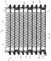
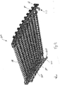
- As shown in
FIG. 1 , a spiral overlay or meshoverlay conveyor belt 10 is comprised ofwire spirals 12 intermeshed together by connectingrods 14 extending across the conveyor belt in the transverse direction. The ends of the rods extend throughlinks 16 which pivotally connect adjacent rods, and are arranged along the side edges of the conveyor. The links also serve as tractive links in that they engage the sprockets which drive the conveyor. - Fatigue failure on the positively driven edge of the mesh overlay belt has been a concern in the past, as well as maintaining the belt in the proper position on the spiral conveyor.
- Accordingly, there exists a need in the marketplace for a conveyor belt having an edge configuration for maintaining belt orientation, providing improved positive edge drive capability, and reducing fatigue failures on the driven edges of the conveyor belt.
- A conveyor belt comprising a plurality of spaced tractive rods; a plurality of rows transversely disposed with respect to a direction of travel and interconnecting said plurality of spaced tractive rods; a plurality of belt drive clips; and wherein each of said rows comprises a U-shaped link on each edge and a mesh overlay extending therebetween. According to a further aspect of the disclosure, at least some of the U-shaped links include an integral hold-down clip; wherein said conveyor belt includes opposing first and second outer edges and said plurality of belt drive clips and/or U-shaped links with the integral hold-down clip are disposed on at least one of the first and second outer edges of the conveyor belt.
- A conveyor belt with improved edge drive capability, said conveyor belt comprising a plurality of spaced tractive rods; a plurality of pitch rows transversely disposed with respect to a direction of travel and interconnecting said plurality of spaced tractive rods; and a plurality of belt drive clips; wherein each of said rows comprises a U-shaped link on each edge and a mesh overlay extending therebetween; wherein at least some of the U-shaped links include an edge guard; and wherein said conveyor belt includes opposing first and second outer edges and said plurality of belt drive clips and/or U-shaped links with the integral hold-down clip are disposed on at least one of the first and second outer edges of the conveyor belt.
- These and other objects, features, and advantages of the invention will become more readily apparent to those skilled in the art upon reading the following detailed description, in conjunction with the appended drawings in which:
-
FIG. 1 is a top elevational, partly schematic view with portions broken away, of a segment of a conventional spiral mesh overlay conveyor belt. -
FIG. 2 is a top elevational view of a conveyor belt according to an exemplary embodiment of the disclosure. -
FIG. 3 is a top elevational view of a conveyor belt according to a further exemplary embodiment of the disclosure. -
FIG. 4 is a perspective view thereof. -
FIG. 5 is a top elevational view thereof in engagement with a sprocket. -
FIG. 6 is a perspective view thereof in engagement with a sprocket. -
FIG. 7 is a further perspective view thereof in engagement with a sprocket. -
FIG. 8 is a perspective view thereof in engagement with a support rail. -
FIG. 9 is a perspective view of a conveyor belt according to a further exemplary embodiment of the disclosure. -
FIG. 10 is perspective view of a conveyor belt according to a further exemplary embodiment of the disclosure. -
FIG. 11 is perspective view of a link in the conveyor belt ofFIG. 10 . -
FIG. 12 is a further perspective view of a link in the conveyor belt ofFIG. 10 . -
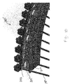
FIG. 13 is perspective view of a conveyor belt according to a further exemplary embodiment of the disclosure. -
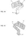
FIG. 14 is perspective view of a link in the conveyor belt ofFIG. 13 . -
FIG. 15 is perspective view of a link which is the mirror image of the link shown inFIG. 14 . - An edge drive mesh overlay conveyor belt will be described below by reference to the embodiments disclosed here as examples and in accordance with the attached drawings. In the following descriptions of the various embodiments disclosed herein, it is understood that like reference numerals are used to describe the same elements throughout.
- A
conveyor belt belt drive clips 50 and a plurality of hold-down clips 60, is shown inFIGS. 2-8 . Thebelt drive clips 50 are preferably formed in a J-shape on every pitch, or support row, and a hold-downclip 60 is preferably positioned every third pitch, or support row, in an overlapping pattern. Other patterns such as every pitch, every other pitch, etc., could also be used. Astandard reinforcing bar 140, or a plurality of bars, may also be inserted into thebelt 100 on those pitches, or support row, where no hold-downclip 60 is used. - The
belt drive clip 50 and the hold-downclip 60 are fully disclosed inU.S. Patent No. 9,061,829 - A conveyor belt in accordance with a first embodiment of the disclosure here is shown generally in
FIG. 2 byreference numeral 100.Conveyor belt 100 preferably comprises a mesh overlay conveyor belt, although other belt types and configurations could of course be used.Conveyor belt 100 includes a plurality of spacedtractive rods 180 disposed in succession and transversely with respect to a direction of travel T as represented by arrow T ofbelt 100, eachrod 180 having two ends, each preferably terminating in abuttonhead 210. -
Belt 100 includes a plurality ofsupport rows 160 transversely disposed with respect to the direction of travel T, and interconnecting the succession ofrods 180. Eachrow 160 is comprised of a plurality of U-shapedlinks 170, each link connecting arod 180 with a following rod in the succession. More preferably, eachrow 160 includes at least onelink 170 on each end and amesh overlay 190 extending therebetween. In addition,belt 100 preferably includes one or more rows including a J-shapedbelt drive clip 50, a hold-downclip 60 and a reinforcingbar 140 disposed along at least one edge of the conveyor belt.Belt drive clips 50, hold-downclips 60 and reinforcingbars 140 can be positioned along both edges of the conveyor belt (as shown inFIG. 2 ) depending on the desired construction and function of the particular belt. Still further, while the combined use ofbelt drive clips 50 and hold-down clips 60 is preferable, it is within the scope of the present disclosure that either one could be used by itself in connection with the conveyor belt. That is, theconveyor belt 100 may include onlybelt drive clips 50 and reinforcingbars 140 or, alternatively, only hold-downclips 60 and reinforcingbars 140. As shown inFIG. 3 ,belt 200 includes hold-down clips 60 along one edge (interior edge) andbelt drive clips 50 and hold-downclips 60 along the other edge (exterior edge). Still further,belt - The combination of overlapping J-shaped drive clips and hold-down clips on the outer edge(s) of the conveyor belt with a welded U-shaped link and rod assembly provide support for the position of the metal mesh overlay. The rows of clips and bars along the outer, tension-bearing belt edge provide superior strength to offset the belt tension that results during system operation. The welded assembly of inner and outer U-shaped links and rods provides a structure that eliminates the possibility for excess lateral movement of the rows of bars and links from the inside or outside belt edges while at the same time provides surfaces where the belt can contact the stationary support rails (described further below). It is preferred for the U-shaped links to contact the support rails rather than the mesh overlay in order to reduce the contact pressure between the belt and rail, reducing also the likelihood of component wear.
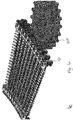
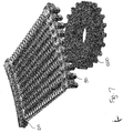
- As illustrated in
FIGS. 5-8 , the belt is driven forward by the engagement with sprockets positioned along the outer periphery of the belt's spiral path. If needed, the belt can also be driven from the top side or underneath using different sprockets to engage the U-shaped links along the belt edges. The J-shaped drive clips 50 are engaged bysprocket 500 driven by a vertically-oriented shaft of a spindle drive (not shown), while the hold-downclips 60 serve to maintain thebelt sprocket 500. A vertical extension portion of the hold-down clip 60 supports the reaction loading on thebelt 100 as a result of engagement with a support rail 510 (FIG. 8 ). Theupstanding member 68 of the hold-downclip 60 as it extends below the thickness of thebelt 100 is typically positioned against astationary support rail 510 and prevents thebelt 100 from inadvertently lifting off of thesupport rail 510. The opposing wings 66 on each side of the hold-downclip 60 are provided to ensure a smooth engagement with therail 510 regardless of the driven direction of thebelt 100. Both thebelt drive clip 50 and the hold-downclip 60 are positioned in an overlapping pattern along withadditional reinforcing bars 140 to act as load carrying members, especially during those times when thebelt 100 is partially collapsed, as in a turn for example. - A conveyor belt in accordance with a further exemplary embodiment is shown generally in
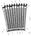
FIG. 9 byreference numeral 300.Conveyor belt 300 preferably comprises a mesh overlay conveyor belt as described above, although other belt types and configurations could of course be used.Conveyor belt 300 includes a plurality of spacedtractive rods 180 disposed in succession and transversely with respect to a direction of travel ofbelt 300, eachrod 180 having two ends preferably terminating in abuttonhead 210. -
Belt 300 includes a plurality ofsupport rows 360 transversely disposed with respect to the direction of travel T, and interconnecting the succession ofrods 180.Belt 300 preferably includes at least one row of J-shaped belt drive clips 50 disposed along at least one edge of the conveyor belt. Eachrow 360 is comprised of a plurality oflinks 310, each link connecting arod 180 with a following rod in the succession. More preferably, each pitch orrow 360 includes at least onelink 310 on each end and amesh overlay 190 preferably extending therebetween.Link 310 includes an integral hold-down clip 315 comprising a dependingextension 320 and anupstanding tab member 325. The dependingextension 320 supports the reaction loading on thebelt 300 as a result of engagement with thesupport rail 510. Theupstanding tab member 325 of the integral hold-down clip 315 extends below the thickness of thebelt 300 and would positioned against a stationary support rail 510 (as shown inFIG. 8 ) and prevents thebelt 100 from inadvertently lifting off of thesupport rail 510. - In a further exemplary embodiment shown in
FIGS. 10-12 , at least onerow 360 includes at least one link 310' on each end and amesh overlay 190 preferably extending therebetween. Link 310' includes an integral hold-down clip 315' comprising a depending extension 320' and an upstanding tab member 325'. As shown inFIG. 10 , links 310' including the integral hold-down clips 315' are provided on every third pitch rather than every pitch as shown inFIG. 9 . As a result of this spacing, the upstanding tab member 325' can be wider so as to increase contact with therail 510. That is, by mixing links that have integral hold-down clips with links that do not have integral hold-down clips in some pre-determined pattern, it is possible to increase the width of the tab member and subsequently the strength of the tab member without interfering with the collapse of the belt or the articulation of the belt links around a roller. As should be apparent to one skilled in the art, link 310' including an integral hold-down clip 315' will be either a left-hand link or a right-hand link depending on which edge of the belt it is to be disposed, one being the mirror image of the other. - Referring also to
FIGS. 13-15 , a further exemplary embodiment according to the disclosure herein includesbelt 400 which combines the integral hold-down clip 315 with aU-shaped link 330 which also has a vertical extension above the top surface of the belt that serves as anedge guard 335 to retain product on the belt. An additional modification ofbelt 400 could include links with edge guards on every other pitch or every third pitch, etc. instead of every pitch as shown. A similar component spacing modification could apply to using links with integral hold-downs. As illustrated, thelink 330 inFIG. 14 is considered a right-hand link and thelink 330 shown inFIG. 15 is considered a left-hand link which is a mirror image of that shown inFIG. 14 and the correct link will be selected depending on which edge of the belt it is to be disposed. - While the combined use of the various embodiments of the belt drive clips, hold-down clips or integral hold-down clips is preferable, it is within the scope of the disclosure that either one could be used by itself in connection with the conveyor belt. That is, the conveyor belt may include only belt drive clips and reinforcing bars or, alternatively, only hold-down clips and reinforcing bars. Still further, the belt may be manufactured without any reinforcing bars or alternatively, several rows of reinforcing bars may be provided, depending upon the particular application. Thus, it should be apparent to one skilled in the art, that any combination of belt drive clips, hold-down clips and/or reinforcing bars may be used depending upon the particular application for which the conveyor belt is intended.
- While the present invention has been described with respect to a particular embodiment of the present invention, this is by way of illustration for purposes of disclosure rather than to confine the invention to any specific arrangement as there are various alterations, changes, deviations, eliminations, substitutions, omissions and departures which may be made in the particular embodiment shown and described without departing from the scope of the claims.
Claims (9)
- A conveyor belt comprising:a plurality of spaced tractive rods;a plurality of support rows transversely disposed with respect to a direction of travel and interconnecting said plurality of spaced tractive rods;a plurality of belt drive clips; anda plurality of belt hold-down clips;wherein said conveyor belt includes opposing first and second outer edges and said plurality of belt drive clips and/or belt hold-down clips are disposed on at least one of the first and second outer edges of the conveyor belt such that said belt drive clips and belt hold-down clips improve the edge drive capability of said conveyor belt;wherein a plurality of said rows comprise a U-shaped link on each edge and a mesh overlay extending therebetween.
- The conveyor belt according to claim 1, wherein each of said plurality of belt hold-down clips includes a base member having at least one opening and an upstanding member disposed substantially perpendicular to said base member, each of said plurality of belt hold-down clips further including opposing wing portions extending from opposing sides of said base member.
- The conveyor belt according to claim 1, wherein each of said plurality of belt clips is generally J-shaped with a first leg portion, a second leg portion, and a connecting portion, the first and second leg portions defining two substantially parallel planes and the connecting portion defining a plane intersecting the two substantially parallel planes, each of said plurality of belt clips having at least one opening in the first leg portion or the second leg portion and no openings in the connecting portion, the openings of each belt drive clip existing entirely in the planes of the first and second leg portions.
- The conveyor belt according to claim 3, wherein the first leg portion has two openings, the second leg portion has one opening, and the connecting portion connects the first and second leg portions.
- A conveyor belt comprising:a plurality of spaced tractive rods;a plurality of rows transversely disposed with respect to a direction of travel and interconnecting said plurality of spaced tractive rods; anda plurality of belt drive clips;wherein a plurality of said rows comprise a U-shaped link on each edge and a mesh overlay extending therebetween;wherein at least some of the U-shaped links include an integral hold-down clip; andwherein said conveyor belt includes opposing first and second outer edges and said plurality of belt drive clips and/or U-shaped links with the integral hold-down clip are disposed on at least one of the first and second outer edges of the conveyor belt.
- The conveyor belt according to claim 5, wherein the integral hold-down clip includes a depending extension and an upstanding tab member.
- The conveyor belt according to claim 5, wherein said at least some of the U-shaped links including the integral hold-down clip includes every third one of said plurality of rows.
- A conveyor belt with improved edge drive capability, said conveyor belt comprising:a plurality of spaced tractive rods;a plurality of pitch rows transversely disposed with respect to a direction of travel and interconnecting said plurality of spaced tractive rods; anda plurality of belt drive clips;wherein each of said rows comprises a U-shaped link on each edge and a mesh overlay extending therebetween;wherein at least some of the U-shaped links include an edge guard; andwherein said conveyor belt includes opposing first and second outer edges and said plurality of belt drive clips and/or U-shaped links with the edge guard are disposed on at least one of the first and second outer edges of the conveyor belt.
- The conveyor belt according to claim 8, wherein at least some of the U-shaped links include an integral hold-down clip.
Applications Claiming Priority (1)
| Application Number | Priority Date | Filing Date | Title |
|---|---|---|---|
| US201662394451P | 2016-09-14 | 2016-09-14 |
Publications (1)
| Publication Number | Publication Date |
|---|---|
| EP3330203A1 true EP3330203A1 (en) | 2018-06-06 |
Family
ID=59895116
Family Applications (1)
| Application Number | Title | Priority Date | Filing Date |
|---|---|---|---|
| EP17190882.5A Pending EP3330203A1 (en) | 2016-09-14 | 2017-09-13 | Edge drive mesh overlay conveyor belt |
Country Status (3)
| Country | Link |
|---|---|
| US (1) | US10577183B2 (en) |
| EP (1) | EP3330203A1 (en) |
| CN (1) | CN107814134A (en) |
Cited By (1)
| Publication number | Priority date | Publication date | Assignee | Title |
|---|---|---|---|---|
| US10507978B2 (en) | 2017-10-28 | 2019-12-17 | Rabbit Designs LLC | Radius and variable width conveyor belt |
Families Citing this family (5)
| Publication number | Priority date | Publication date | Assignee | Title |
|---|---|---|---|---|
| EP3257793B1 (en) * | 2016-06-13 | 2020-09-23 | Frans Bakker Beheer B.V. | Conveyor belt |
| ZA201904027B (en) * | 2018-06-22 | 2022-04-28 | Dale Holdings Pty Ltd | Positive drive conveyor |
| IT201900006102A1 (en) * | 2019-04-18 | 2020-10-18 | Incobra S R L | CONNECTION MESH FOR SUPPORT ELEMENTS FOR CONVEYOR BELTS, SUPPORT ELEMENTS FOR CONVEYOR BELTS, METHOD FOR MAKING THE CONNECTION MESH AND SUPPORT ELEMENT |
| CN113296142B (en) * | 2021-05-21 | 2023-01-17 | 山西中辐核仪器有限责任公司 | Conveyer belt type safety helmet pollution monitor |
| US12091256B2 (en) | 2021-09-16 | 2024-09-17 | Cambridge International, Inc. | Material buildup resistant sprocket |
Citations (9)
| Publication number | Priority date | Publication date | Assignee | Title |
|---|---|---|---|---|
| US3920117A (en) * | 1974-04-23 | 1975-11-18 | Ashworth Bros Inc | Wire conveyor belt |
| EP0850858A1 (en) * | 1993-09-03 | 1998-07-01 | Ashworth Bros. Inc. | Conveyor belt with spiral overlay |
| NL1018669C2 (en) * | 2001-07-31 | 2003-02-03 | Esfo B V | Conveyor belt comprises at least first and second, parallel, spaced apart link chains between which extend connecting rods, at least part of which extend past at least first link chain |
| DE202006004102U1 (en) * | 2005-04-27 | 2006-05-11 | Tecno Pool S.P.A., S. Giorgio In Bosco | System of lateral enclosure for conveyor belt has several cross struts and enclosures of self lubricating material with mounting device to interconnect successive cross struts with enclosures |
| WO2007076532A2 (en) * | 2005-12-29 | 2007-07-05 | Span Tech Llc | Composite conveyor with serrated intermediate links |
| EP2248741A1 (en) * | 2009-05-08 | 2010-11-10 | Alit S.r.l. | Link of a side chain for conveyor belts |
| WO2014040827A1 (en) * | 2012-09-14 | 2014-03-20 | Alit S.R.L. | Link for a lateral chain for conveyor belts |
| WO2015079412A1 (en) * | 2013-11-27 | 2015-06-04 | Millennium Engineering S.R.L. | Conveyor chain in particular for food products |
| US9061829B2 (en) | 2011-10-26 | 2015-06-23 | Cambridge International, Inc. | Conveyor belt with improved edge configuration |
Family Cites Families (7)
| Publication number | Priority date | Publication date | Assignee | Title |
|---|---|---|---|---|
| FR2503106B1 (en) * | 1981-04-03 | 1986-04-18 | Frigofrance Sa | CONTINUOUS BELT CONVEYOR DESCRIBING A HELICOIDE |
| ITMI20061395A1 (en) * | 2006-07-18 | 2008-01-19 | Tecno Pool Spa | CONVEYOR BELT OF A CHAIN CONVEYOR WITH INNOVATIVE DRIVING JERSEYS. |
| IT1390848B1 (en) * | 2008-07-31 | 2011-10-19 | Neuroscienze Pharmaness S C A R L | PHARMACEUTICAL COMPOUNDS |
| IT1392854B1 (en) * | 2009-02-13 | 2012-03-23 | Tecno Pool Spa | BAR CONVEYOR BELT, PARTICULARLY FOR THE FOOD INDUSTRY. |
| US8985318B2 (en) * | 2012-05-15 | 2015-03-24 | Ashworth Bros., Inc. | Conveyor belt with composite link |
| CA2896682C (en) * | 2012-12-27 | 2017-01-24 | Mayekawa Mfg. Co., Ltd. | Conveyor device for conveying food |
| BR112015015279B1 (en) * | 2012-12-27 | 2021-03-02 | Mayekawa Mfg. Co., Ltd | conveyor device for transporting food |
-
2017
- 2017-09-12 US US15/702,200 patent/US10577183B2/en active Active
- 2017-09-13 EP EP17190882.5A patent/EP3330203A1/en active Pending
- 2017-09-14 CN CN201710825780.7A patent/CN107814134A/en active Pending
Patent Citations (9)
| Publication number | Priority date | Publication date | Assignee | Title |
|---|---|---|---|---|
| US3920117A (en) * | 1974-04-23 | 1975-11-18 | Ashworth Bros Inc | Wire conveyor belt |
| EP0850858A1 (en) * | 1993-09-03 | 1998-07-01 | Ashworth Bros. Inc. | Conveyor belt with spiral overlay |
| NL1018669C2 (en) * | 2001-07-31 | 2003-02-03 | Esfo B V | Conveyor belt comprises at least first and second, parallel, spaced apart link chains between which extend connecting rods, at least part of which extend past at least first link chain |
| DE202006004102U1 (en) * | 2005-04-27 | 2006-05-11 | Tecno Pool S.P.A., S. Giorgio In Bosco | System of lateral enclosure for conveyor belt has several cross struts and enclosures of self lubricating material with mounting device to interconnect successive cross struts with enclosures |
| WO2007076532A2 (en) * | 2005-12-29 | 2007-07-05 | Span Tech Llc | Composite conveyor with serrated intermediate links |
| EP2248741A1 (en) * | 2009-05-08 | 2010-11-10 | Alit S.r.l. | Link of a side chain for conveyor belts |
| US9061829B2 (en) | 2011-10-26 | 2015-06-23 | Cambridge International, Inc. | Conveyor belt with improved edge configuration |
| WO2014040827A1 (en) * | 2012-09-14 | 2014-03-20 | Alit S.R.L. | Link for a lateral chain for conveyor belts |
| WO2015079412A1 (en) * | 2013-11-27 | 2015-06-04 | Millennium Engineering S.R.L. | Conveyor chain in particular for food products |
Cited By (2)
| Publication number | Priority date | Publication date | Assignee | Title |
|---|---|---|---|---|
| US10507978B2 (en) | 2017-10-28 | 2019-12-17 | Rabbit Designs LLC | Radius and variable width conveyor belt |
| US10633187B2 (en) | 2017-10-28 | 2020-04-28 | Rabbit Designs LLC | Radius and variable width conveyor belt |
Also Published As
| Publication number | Publication date |
|---|---|
| CN107814134A (en) | 2018-03-20 |
| US20180072504A1 (en) | 2018-03-15 |
| US10577183B2 (en) | 2020-03-03 |
Similar Documents
| Publication | Publication Date | Title |
|---|---|---|
| US10577183B2 (en) | Edge drive mesh overlay conveyor belt | |
| US9061829B2 (en) | Conveyor belt with improved edge configuration | |
| US9475642B2 (en) | Variable spaced conveyor belt with clinched rod ends | |
| EP3369681B1 (en) | Direct edge drive conveyor belt | |
| JP5022357B2 (en) | Sludge scraping device chain device | |
| EP2200913B1 (en) | Flat wire conveyor belt system | |
| US9169074B2 (en) | Variable width drive openings for conveyor belt | |
| US5350056A (en) | Self-supporting conveyor belt with wire-formed spacers | |
| US10035681B2 (en) | Belt-driven people conveyor | |
| US20150191312A1 (en) | Variable spaced conveyor belt with shortened edge link cut-off | |
| EP1770028A1 (en) | Wire conveyor belt with tension transfer | |
| EP2655224B1 (en) | Improved lateral plate element for a link means included in a self-stacking endless conveyor belt | |
| JPH0692426A (en) | Modular plactic rotation belt conveyor system, module, belt and device to drive the same | |
| JP6156887B2 (en) | Composite link and conveyor belt having the same | |
| US20140367229A1 (en) | Rod belt for a rod belt conveyor for agricultural machinery | |
| EP1223119A1 (en) | Wire belt with compound link formation | |
| EP0344411B1 (en) | Curved track plate conveyor | |
| CN111670152B (en) | Splicing system for conveyor belt | |
| KR101690844B1 (en) | Conveyor belt with alignment features | |
| US20150361661A1 (en) | Bar of a support structure for a false ceiling and working process for working the bar | |
| WO2002081342A1 (en) | Vertical conveyor in the form of a c-shaped circulating conveyor for vertical conveyance of unit load items | |
| JPH0615362B2 (en) | Conveyor belt | |
| US10118766B2 (en) | Splice link for conveyor belt | |
| US4487013A (en) | T-rod chain | |
| DE3844855C2 (en) | Curved conveyor with hinged plates |
Legal Events
| Date | Code | Title | Description |
|---|---|---|---|
| PUAI | Public reference made under article 153(3) epc to a published international application that has entered the european phase |
Free format text: ORIGINAL CODE: 0009012 |
|
| STAA | Information on the status of an ep patent application or granted ep patent |
Free format text: STATUS: THE APPLICATION HAS BEEN PUBLISHED |
|
| AK | Designated contracting states |
Kind code of ref document: A1 Designated state(s): AL AT BE BG CH CY CZ DE DK EE ES FI FR GB GR HR HU IE IS IT LI LT LU LV MC MK MT NL NO PL PT RO RS SE SI SK SM TR |
|
| AX | Request for extension of the european patent |
Extension state: BA ME |
|
| STAA | Information on the status of an ep patent application or granted ep patent |
Free format text: STATUS: REQUEST FOR EXAMINATION WAS MADE |
|
| 17P | Request for examination filed |
Effective date: 20181206 |
|
| RBV | Designated contracting states (corrected) |
Designated state(s): AL AT BE BG CH CY CZ DE DK EE ES FI FR GB GR HR HU IE IS IT LI LT LU LV MC MK MT NL NO PL PT RO RS SE SI SK SM TR |
|
| STAA | Information on the status of an ep patent application or granted ep patent |
Free format text: STATUS: EXAMINATION IS IN PROGRESS |
|
| 17Q | First examination report despatched |
Effective date: 20190821 |
|
| STAA | Information on the status of an ep patent application or granted ep patent |
Free format text: STATUS: EXAMINATION IS IN PROGRESS |
|
| P01 | Opt-out of the competence of the unified patent court (upc) registered |
Effective date: 20240111 |
|
| GRAP | Despatch of communication of intention to grant a patent |
Free format text: ORIGINAL CODE: EPIDOSNIGR1 |
|
| STAA | Information on the status of an ep patent application or granted ep patent |
Free format text: STATUS: GRANT OF PATENT IS INTENDED |
|
| INTG | Intention to grant announced |
Effective date: 20240816 |