JP6156887B2 - Composite link and conveyor belt having the same - Google Patents
Composite link and conveyor belt having the same Download PDFInfo
- Publication number
- JP6156887B2 JP6156887B2 JP2015512729A JP2015512729A JP6156887B2 JP 6156887 B2 JP6156887 B2 JP 6156887B2 JP 2015512729 A JP2015512729 A JP 2015512729A JP 2015512729 A JP2015512729 A JP 2015512729A JP 6156887 B2 JP6156887 B2 JP 6156887B2
- Authority
- JP
- Japan
- Prior art keywords
- link
- conveyor belt
- support structure
- rod
- covering
- Prior art date
- Legal status (The legal status is an assumption and is not a legal conclusion. Google has not performed a legal analysis and makes no representation as to the accuracy of the status listed.)
- Active
Links
- 239000002131 composite material Substances 0.000 title claims description 76
- 239000000463 material Substances 0.000 claims description 44
- 239000004033 plastic Substances 0.000 claims description 35
- 229920003023 plastic Polymers 0.000 claims description 34
- 229910052751 metal Inorganic materials 0.000 claims description 33
- 239000002184 metal Substances 0.000 claims description 33
- 230000014759 maintenance of location Effects 0.000 claims description 20
- 239000011248 coating agent Substances 0.000 claims description 11
- 238000000576 coating method Methods 0.000 claims description 11
- 230000007246 mechanism Effects 0.000 claims description 9
- 229910000831 Steel Inorganic materials 0.000 claims description 8
- 239000010959 steel Substances 0.000 claims description 8
- 239000000919 ceramic Substances 0.000 claims description 5
- 229910052782 aluminium Inorganic materials 0.000 claims description 4
- XAGFODPZIPBFFR-UHFFFAOYSA-N aluminium Chemical compound [Al] XAGFODPZIPBFFR-UHFFFAOYSA-N 0.000 claims description 4
- 238000003780 insertion Methods 0.000 claims description 4
- 230000037431 insertion Effects 0.000 claims description 4
- 229910001369 Brass Inorganic materials 0.000 claims description 3
- 239000010951 brass Substances 0.000 claims description 3
- 239000000835 fiber Substances 0.000 claims description 3
- 239000011295 pitch Substances 0.000 description 48
- 238000000034 method Methods 0.000 description 23
- 230000008569 process Effects 0.000 description 11
- 238000004519 manufacturing process Methods 0.000 description 7
- RLLPVAHGXHCWKJ-IEBWSBKVSA-N (3-phenoxyphenyl)methyl (1s,3s)-3-(2,2-dichloroethenyl)-2,2-dimethylcyclopropane-1-carboxylate Chemical compound CC1(C)[C@H](C=C(Cl)Cl)[C@@H]1C(=O)OCC1=CC=CC(OC=2C=CC=CC=2)=C1 RLLPVAHGXHCWKJ-IEBWSBKVSA-N 0.000 description 6
- 230000008901 benefit Effects 0.000 description 5
- 229910001220 stainless steel Inorganic materials 0.000 description 4
- 239000010935 stainless steel Substances 0.000 description 4
- 238000005520 cutting process Methods 0.000 description 3
- 239000007769 metal material Substances 0.000 description 3
- 238000011282 treatment Methods 0.000 description 3
- 238000005266 casting Methods 0.000 description 2
- 239000004744 fabric Substances 0.000 description 2
- 238000005242 forging Methods 0.000 description 2
- 238000012986 modification Methods 0.000 description 2
- 230000004048 modification Effects 0.000 description 2
- 229920000049 Carbon (fiber) Polymers 0.000 description 1
- RTAQQCXQSZGOHL-UHFFFAOYSA-N Titanium Chemical compound [Ti] RTAQQCXQSZGOHL-UHFFFAOYSA-N 0.000 description 1
- 238000005299 abrasion Methods 0.000 description 1
- 239000004917 carbon fiber Substances 0.000 description 1
- 238000009750 centrifugal casting Methods 0.000 description 1
- 238000005260 corrosion Methods 0.000 description 1
- 230000007797 corrosion Effects 0.000 description 1
- 238000004132 cross linking Methods 0.000 description 1
- 238000010586 diagram Methods 0.000 description 1
- 238000004512 die casting Methods 0.000 description 1
- 238000010438 heat treatment Methods 0.000 description 1
- 238000005304 joining Methods 0.000 description 1
- 238000003754 machining Methods 0.000 description 1
- 238000007620 mathematical function Methods 0.000 description 1
- 150000002739 metals Chemical class 0.000 description 1
- VNWKTOKETHGBQD-UHFFFAOYSA-N methane Chemical compound C VNWKTOKETHGBQD-UHFFFAOYSA-N 0.000 description 1
- 229910052755 nonmetal Inorganic materials 0.000 description 1
- 229920000642 polymer Polymers 0.000 description 1
- 238000010791 quenching Methods 0.000 description 1
- 230000000171 quenching effect Effects 0.000 description 1
- 239000011347 resin Substances 0.000 description 1
- 229920005989 resin Polymers 0.000 description 1
- 239000005060 rubber Substances 0.000 description 1
- 238000007528 sand casting Methods 0.000 description 1
- 239000007787 solid Substances 0.000 description 1
- 229910052719 titanium Inorganic materials 0.000 description 1
- 239000010936 titanium Substances 0.000 description 1
- 230000007704 transition Effects 0.000 description 1
- 238000003466 welding Methods 0.000 description 1
- 239000002023 wood Substances 0.000 description 1
Images


Classifications
-
- B—PERFORMING OPERATIONS; TRANSPORTING
- B65—CONVEYING; PACKING; STORING; HANDLING THIN OR FILAMENTARY MATERIAL
- B65G—TRANSPORT OR STORAGE DEVICES, e.g. CONVEYORS FOR LOADING OR TIPPING, SHOP CONVEYOR SYSTEMS OR PNEUMATIC TUBE CONVEYORS
- B65G15/00—Conveyors having endless load-conveying surfaces, i.e. belts and like continuous members, to which tractive effort is transmitted by means other than endless driving elements of similar configuration
- B65G15/30—Belts or like endless load-carriers
- B65G15/54—Endless load-carriers made of interwoven ropes or wires
-
- B—PERFORMING OPERATIONS; TRANSPORTING
- B65—CONVEYING; PACKING; STORING; HANDLING THIN OR FILAMENTARY MATERIAL
- B65G—TRANSPORT OR STORAGE DEVICES, e.g. CONVEYORS FOR LOADING OR TIPPING, SHOP CONVEYOR SYSTEMS OR PNEUMATIC TUBE CONVEYORS
- B65G17/00—Conveyors having an endless traction element, e.g. a chain, transmitting movement to a continuous or substantially-continuous load-carrying surface or to a series of individual load-carriers; Endless-chain conveyors in which the chains form the load-carrying surface
- B65G17/06—Conveyors having an endless traction element, e.g. a chain, transmitting movement to a continuous or substantially-continuous load-carrying surface or to a series of individual load-carriers; Endless-chain conveyors in which the chains form the load-carrying surface having a load-carrying surface formed by a series of interconnected, e.g. longitudinal, links, plates, or platforms
- B65G17/063—Conveyors having an endless traction element, e.g. a chain, transmitting movement to a continuous or substantially-continuous load-carrying surface or to a series of individual load-carriers; Endless-chain conveyors in which the chains form the load-carrying surface having a load-carrying surface formed by a series of interconnected, e.g. longitudinal, links, plates, or platforms the load carrying surface being formed by profiles, rods, bars, rollers or the like attached to more than one traction element
-
- B—PERFORMING OPERATIONS; TRANSPORTING
- B65—CONVEYING; PACKING; STORING; HANDLING THIN OR FILAMENTARY MATERIAL
- B65G—TRANSPORT OR STORAGE DEVICES, e.g. CONVEYORS FOR LOADING OR TIPPING, SHOP CONVEYOR SYSTEMS OR PNEUMATIC TUBE CONVEYORS
- B65G17/00—Conveyors having an endless traction element, e.g. a chain, transmitting movement to a continuous or substantially-continuous load-carrying surface or to a series of individual load-carriers; Endless-chain conveyors in which the chains form the load-carrying surface
- B65G17/06—Conveyors having an endless traction element, e.g. a chain, transmitting movement to a continuous or substantially-continuous load-carrying surface or to a series of individual load-carriers; Endless-chain conveyors in which the chains form the load-carrying surface having a load-carrying surface formed by a series of interconnected, e.g. longitudinal, links, plates, or platforms
- B65G17/08—Conveyors having an endless traction element, e.g. a chain, transmitting movement to a continuous or substantially-continuous load-carrying surface or to a series of individual load-carriers; Endless-chain conveyors in which the chains form the load-carrying surface having a load-carrying surface formed by a series of interconnected, e.g. longitudinal, links, plates, or platforms the surface being formed by the traction element
- B65G17/083—Conveyors having an endless traction element, e.g. a chain, transmitting movement to a continuous or substantially-continuous load-carrying surface or to a series of individual load-carriers; Endless-chain conveyors in which the chains form the load-carrying surface having a load-carrying surface formed by a series of interconnected, e.g. longitudinal, links, plates, or platforms the surface being formed by the traction element the surface being formed by profiles, rods, bars, rollers or the like
-
- B—PERFORMING OPERATIONS; TRANSPORTING
- B65—CONVEYING; PACKING; STORING; HANDLING THIN OR FILAMENTARY MATERIAL
- B65G—TRANSPORT OR STORAGE DEVICES, e.g. CONVEYORS FOR LOADING OR TIPPING, SHOP CONVEYOR SYSTEMS OR PNEUMATIC TUBE CONVEYORS
- B65G17/00—Conveyors having an endless traction element, e.g. a chain, transmitting movement to a continuous or substantially-continuous load-carrying surface or to a series of individual load-carriers; Endless-chain conveyors in which the chains form the load-carrying surface
- B65G17/06—Conveyors having an endless traction element, e.g. a chain, transmitting movement to a continuous or substantially-continuous load-carrying surface or to a series of individual load-carriers; Endless-chain conveyors in which the chains form the load-carrying surface having a load-carrying surface formed by a series of interconnected, e.g. longitudinal, links, plates, or platforms
- B65G17/08—Conveyors having an endless traction element, e.g. a chain, transmitting movement to a continuous or substantially-continuous load-carrying surface or to a series of individual load-carriers; Endless-chain conveyors in which the chains form the load-carrying surface having a load-carrying surface formed by a series of interconnected, e.g. longitudinal, links, plates, or platforms the surface being formed by the traction element
- B65G17/086—Conveyors having an endless traction element, e.g. a chain, transmitting movement to a continuous or substantially-continuous load-carrying surface or to a series of individual load-carriers; Endless-chain conveyors in which the chains form the load-carrying surface having a load-carrying surface formed by a series of interconnected, e.g. longitudinal, links, plates, or platforms the surface being formed by the traction element specially adapted to follow a curved path
-
- B—PERFORMING OPERATIONS; TRANSPORTING
- B65—CONVEYING; PACKING; STORING; HANDLING THIN OR FILAMENTARY MATERIAL
- B65G—TRANSPORT OR STORAGE DEVICES, e.g. CONVEYORS FOR LOADING OR TIPPING, SHOP CONVEYOR SYSTEMS OR PNEUMATIC TUBE CONVEYORS
- B65G2812/00—Indexing codes relating to the kind or type of conveyors
- B65G2812/02—Belt or chain conveyors
- B65G2812/02128—Belt conveyors
Landscapes
- Engineering & Computer Science (AREA)
- Mechanical Engineering (AREA)
- Textile Engineering (AREA)
- Chain Conveyers (AREA)
- Belt Conveyors (AREA)
- Structure Of Belt Conveyors (AREA)
Description
本開示は、一般にモジュール式コンベアベルトのコンポーネントに関するものである。より具体的には、本開示はモジュール式コンベアベルトの複合リンク(composite link)に関するものである。 The present disclosure relates generally to components of modular conveyor belts. More specifically, the present disclosure relates to a composite link for modular conveyor belts.
コンベアベルトは複数の異なる工業分野で製造、出荷および他のプロセス中に商品の連続移動を施すために広く使用されている。工業用コンベアベルトは一般に、ロッドに溶接または他の形で連結されている一連のリンクを介して接続されている一連の離間ロッドを含む。該ベルトは通例モジュール式コンベアベルトと呼ばれる。 Conveyor belts are widely used in a number of different industrial fields to provide continuous movement of goods during manufacturing, shipping and other processes. Industrial conveyor belts typically include a series of spaced rods connected via a series of links that are welded or otherwise connected to the rods. The belt is commonly referred to as a modular conveyor belt.
小型品の製造の場合、ロッドにメッシュなどの布製、プラスチック製または金属製のオーバーレイを被覆して、小型品がロッド間で滑って、製造フロアに落下しないようにしてもよい。また、モジュール式コンベアベルトを構成するリンクの構造は多様である。 In the case of manufacturing a small product, the rod may be covered with a cloth, plastic, or metal overlay such as a mesh to prevent the small product from sliding between the rods and falling onto the manufacturing floor. Moreover, the structure of the link which comprises a modular conveyor belt is various.
一般に、コンベアベルトおよびリンクは金属またはプラスチックのいずれかから作られている。金属製のコンベアベルトのリンクは通例優れた強度特性を有するが、リンクがロッドに接触する面に摩耗を示す。 In general, conveyor belts and links are made from either metal or plastic. Metal conveyor belt links typically have excellent strength properties, but show wear on the surfaces where the links contact the rods.
他方で、プラスチック製のコンベアベルトのリンクは通例接触面での摩耗に耐性があるが、金属製のベルトよりも強度が低いことがあることから、よく疲労および/または過剰な荷重に起因した故障を生じる。 On the other hand, plastic conveyor belt links are typically resistant to wear on the contact surface, but may be less strong than metal belts, so failure due to fatigue and / or excessive loading is often the case. Produce.
一般に、金属製およびプラスチック製のベルトは通例破壊様式に関して異なるが、同等な金属製ベルトおよびプラスチック製ベルトは普通同様な寿命を有する。すなわち、金属製のベルトは普通同様な作業用に構成されているプラスチック製ベルトと同程度長持ちするが、プラスチック製ベルトは通例疲労または瞬間的な荷重の急増により故障するのに対し、金属製のベルトは摩耗により故障する。 In general, metal and plastic belts typically differ in terms of failure mode, but comparable metal and plastic belts usually have similar life. That is, metal belts last as long as plastic belts that are usually configured for similar work, whereas plastic belts usually fail due to fatigue or momentary spikes, while metal belts The belt fails due to wear.
同様に構成されているプラスチック製および金属製のリンクの場合、金属製リンクは同等のプラスチック製リンクの2〜3倍の引張り強度を有する。さらに、ターンカーブコンベアベルトの別個の部分は荷重のかかり方が異なるので、コンベアベルトの所定の部分にとっては最適な材料が他の部分にはあまり適していないことがある。 In the case of plastic and metal links that are similarly constructed, the metal link has a tensile strength two to three times that of an equivalent plastic link. Furthermore, because the separate parts of the turn curve conveyor belt are loaded differently, the optimal material for a given part of the conveyor belt may not be well suited for the other part.
コンベアベルトおよび/またはコンベアベルトのリンクに関して以上の問題および他の問題が存在する。 These and other problems exist with respect to conveyor belts and / or conveyor belt links.
強度を与えるとともに疲労を防止する材料および摩耗を低減する材料から作られているコンベアベルトのエッジリンクと、当該エッジおよび他の同様なリンクを組み込んでいるコンベアベルトとを説明する。 A conveyor belt edge link made of a material that provides strength and prevents fatigue and wear is described, and a conveyor belt incorporating the edge and other similar links.
本発明では、リンクは、リンクに強度を与える金属接続構造物(metal connecting structure)と、金属同士の接触を阻止することによってリンクの表面上の摩耗を低減する被覆構造物(bearing structure)とから作られている複合リンク(composite link)である。これにより、リンクは、強度があって、プラスチックよりも疲労しにくい金属製リンクと、金属製リンクほど摩耗しやすくないプラスチック製リンクとの両方の利点を有することができる。 In the present invention, the link consists of a metal connecting structure that provides strength to the link and a bearing structure that reduces wear on the surface of the link by preventing metal-to-metal contact. It is a composite link that has been created. This allows the link to have the advantages of both a metallic link that is strong and less tiring than plastic and a plastic link that is less susceptible to wear than a metallic link.
ある側面において、本開示はモジュール式コンベアベルトのリンクに向けられている。リンクは支持構造物(supporting structure)と、支持構造物の少なくとも一部を被覆している被覆構造物(bearing structure)とを含んでもよい。支持構造物は被覆構造物よりも高い引張り強度を有し、被覆構造物は支持構造物よりも耐摩耗性が高いことが好ましい。 In one aspect, the present disclosure is directed to a modular conveyor belt link. The link may include a supporting structure and a covering structure that covers at least a portion of the supporting structure. The support structure has a higher tensile strength than the covering structure, and the covering structure preferably has higher wear resistance than the support structure.
別の側面において、本開示は細長い接続ロッドと駆動機構とを含むモジュール式コンベアベルトのリンクに向けられている。リンクは第1材料から作られている支持構造物を含んでもよく、支持構造物は複合リンクの形状を確立している輪郭を含む。さらに、リンクは第2材料から作られている被覆構造物を含んでもよく、被覆構造物は少なくとも1つのコンベアベルトのコンポーネントを係合するように構成されている支持構造物の係合面に配置されている。被覆構造物は少なくとも1つのコンベアベルトのコンポーネントが支持構造物の係合面に接触しないように構成されていてもよい。 In another aspect, the present disclosure is directed to a modular conveyor belt link that includes an elongated connecting rod and a drive mechanism. The link may include a support structure made from the first material, the support structure including a contour establishing the shape of the composite link. Further, the link may include a covering structure made of a second material, the covering structure being disposed on an engagement surface of a support structure configured to engage at least one conveyor belt component. Has been. The covering structure may be configured such that at least one conveyor belt component does not contact the engagement surface of the support structure.
別の側面において、本開示は少なくとも第1リンクおよび第2リンクと、第1リンクおよび第2リンクを互いにヒンジ式に装着するように構成されている細長い接続ロッドとを含むモジュール式コンベアベルトに向けられている。第1リンクは支持構造物と支持構造物の少なくとも一部を被覆している被覆構造物とを含んでもよく、支持構造物は被覆構造物よりも高い引張り強さを有し、被覆構造物は支持構造物よりも耐摩耗性が高い。 In another aspect, the present disclosure is directed to a modular conveyor belt that includes at least a first link and a second link and an elongated connecting rod configured to hingeably attach the first link and the second link to each other. It has been. The first link may include a support structure and a covering structure covering at least a portion of the support structure, the support structure having a higher tensile strength than the covering structure, Higher wear resistance than the support structure.
本発明の他のシステム、方法、特徴および利点は、以下の図面および詳細な説明を調べれば当業者には明らかであろう、または明らかになろう。当該すべての追加のシステム、方法、特徴および利点は本明細書および本概要に含まれ、本発明の範囲内であり、以下の請求項によって保護されることが意図される。 Other systems, methods, features and advantages of the present invention will be or will be apparent to those skilled in the art upon examination of the following drawings and detailed description. All such additional systems, methods, features and advantages are included herein and in this summary, are within the scope of the invention, and are intended to be protected by the following claims.
本発明は以下の図面および説明を参照するとよりよく理解することができる。図面のコンポーネントは必ずしも縮尺通りではなく、代わりに本発明の原理を例示するにあたり強調を施している。さらに、図面において、同じ参照番号はさまざまな図を通して対応する部品を指す。 The invention can be better understood with reference to the following drawings and description. The components in the drawings are not necessarily to scale, emphasis instead being placed upon illustrating the principles of the invention. Moreover, in the drawings, like reference numerals designate corresponding parts throughout the different views.
本開示は、モジュール式コンベアベルトのリンクに耐摩耗性および強度をともに与えるためのシステムおよび方法を説明する。 The present disclosure describes a system and method for providing both wear resistance and strength to a modular conveyor belt link.
基本的なコンベアベルトの構造および製造方法の実施例は、特許文献1で確認することができ、これを参照によりここに組み込む。添付の図1は’特許文献1の図1に対応し、典型的な先行技術のモジュール式コンベアベルト10を示す。コンベアベルト10は、リンク14によって接続されているとともに、コンベアベルト10上に搬送される商品の追加支持を与えるためにメッシュ16によって被覆されているロッド12を含む。
An example of the basic conveyor belt structure and manufacturing method can be found in US Pat. The attached FIG. 1 corresponds to FIG. 1 of 'Patent Document 1 and shows a typical prior art
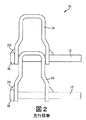
ある場合には、ロッド12の両端に、リンク14のストッパとして作用するボタンヘッド18が形成されていてもよい。ロッド12とリンク14との接続をより強固により確実にするために、ボタンヘッド18とリンク14との間に、通例溶接部も形成されている。他の場合には、ボタンのない構成を採用してもよく、その場合ロッドはリンクの脚部を超えた著しい突出を生じることなくリンクに溶接されている。
In some cases, button heads 18 that act as stoppers for the
図2に、先行技術のコンベアベルト10の一部の拡大図を示す。ボタンヘッド18とともに形成されているロッド12が示されている。さらに、図2はボタンヘッド18を、そのためロッド12をリンク14に固着している溶接部20も示す。
FIG. 2 shows an enlarged view of a portion of a prior
本開示で使用する「コンベアベルト」という用語は、一般に、通例歯車機構またはドラムによって駆動されるように構成されているあらゆる種類の無限軌道またはベルトをいう。「コンベアベルト」という用語は、本明細書に別段の指定がない限り、いずれか特定の種類のコンベアベルトに制限されると見なすべきではない。 As used in this disclosure, the term “conveyor belt” generally refers to any type of endless track or belt that is typically configured to be driven by a gear mechanism or drum. The term “conveyor belt” should not be considered limited to any particular type of conveyor belt, unless otherwise specified herein.
本開示で使用する「側方」または「側方に」という方向を示す用語は、コンベアベルト全体の中心線に対して外に向かう方向をいう。 The term “side” or “to the side” as used in this disclosure refers to the direction outward with respect to the centerline of the entire conveyor belt.
本開示および請求項で使用する「長手」という用語は、コンベアベルトが走行する方向をいう。また、長手という用語はコンベアベルトの走行の前後両方の方向をいう。 The term “longitudinal” as used in this disclosure and claims refers to the direction in which the conveyor belt travels. The term longitudinal refers to both directions before and after the conveyor belt travels.
本開示および請求項で使用する「垂直」という用語は、地面に対する上下方向をいう。 The term “vertical” as used in this disclosure and the claims refers to the up and down direction relative to the ground.
本明細書で説明するコンベアベルトシステムおよび該システムを構築する方法は、さまざまな種類のコンベアベルトを含んでもよい。いくつかの実施形態では、コンベアベルトはモジュール式コンベアベルトであってもよい。モジュール式ベルトは側方に延びている列に配設されて、長手方向に回転可能に接合されている噛合モジュールから形成されていてもよい。ある場合には、モジュール式ベルトの列は側方に配設されていて、例えば接続ロッドによって接合されている複数のモジュールを含んでもよい。モジュール式ベルトモジュールは、各列の前方部および後方部に側方に整列しているロッド穴またはスロットを含んでいてもよい。 The conveyor belt system and method of constructing the system described herein may include various types of conveyor belts. In some embodiments, the conveyor belt may be a modular conveyor belt. The modular belts may be formed from meshing modules that are arranged in rows extending laterally and joined so as to be rotatable in the longitudinal direction. In some cases, the rows of modular belts are arranged laterally and may comprise a plurality of modules joined together, for example by connecting rods. The modular belt module may include rod holes or slots that are laterally aligned at the front and rear of each row.
本開示および請求項で使用する「リンク」という用語は、コンベアベルト列の基本コンポーネントをいう。例えば、リンクの列全体を形成するために、1つの個々のリンクが側方に繰り返されていてもよい。いくつかの実施形態では、列あたり2つだけのリンクが設けられている(ロッドの各端部に)。いくつかの実施形態では、リンクは互いに独立して回転することが可能である。2以上のリンクが互いに堅く装着されていてもよい。 The term “link” as used in the present disclosure and claims refers to the basic components of a conveyor belt train. For example, one individual link may be repeated laterally to form an entire row of links. In some embodiments, there are only two links per row (at each end of the rod). In some embodiments, the links can rotate independently of each other. Two or more links may be firmly attached to each other.
「ロッド」または「接続ロッド」という用語はここでは、リンクを互いに連動させるために使用される細長い部材をいう。連動されているとき、リンクおよびロッドが基本的なモジュール式コンベアベルトを形成する。 The term “rod” or “connecting rod” here refers to an elongate member used to link the links together. When interlocked, the links and rods form a basic modular conveyor belt.
「ピッチ」という用語はここでは、コンベアベルトの一方の側方エッジから反対の側方エッジまで延びている1列のリンクをいう。いくつかの実施形態では、同じ列のすべてのリンクが互いに堅く装着されるように、ピッチは1部材から形成されていてもよい。他の実施形態では、ピッチは複数の個々のリンクを横並びに配列させて、各個々のリンクを互いに対して回転できるようにしてもよい。ピッチは、接続ロッドによって接続されているエンドリンクだけなど、最小限の数のリンクを含んでいてもよい。ピッチはエンドリンクだけでなく、接続ロッドに沿ってエンドリンク間に位置付けられている1以上の離間している中間リンクも含んでいてもよい。 The term “pitch” here refers to a row of links extending from one side edge of the conveyor belt to the opposite side edge. In some embodiments, the pitch may be formed from one member so that all links in the same row are securely attached to each other. In other embodiments, the pitch may be a plurality of individual links arranged side by side so that each individual link can rotate relative to each other. The pitch may include a minimal number of links, such as only end links connected by connecting rods. The pitch may include not only the end links, but also one or more spaced intermediate links positioned between the end links along the connecting rod.
「エンドリンク」という用語は、ここではピッチの最も側方に配設されているリンク、またはある列におけるピッチの終端リンクをいう。各ピッチは、コンベアベルトの各側に1つずつ、2つのエンドリンクを有していてもよい。 The term “end link” here refers to the link that is disposed on the farthest side of the pitch, or the end link of the pitch in a row. Each pitch may have two end links, one on each side of the conveyor belt.
「保持器」という用語は、ここでは保持器がコンベアベルトの中心線から外側になるエンドリンクの側に配置されるように、エンドリンクと連動されている構造物をいう。言い換えると、保持器はコンベアベルトのエッジを形成している。いくつかの実施形態では、保持器は、操作、組み立てまたはあらゆる他の時間中にもロッドがコンベアベルトから不意に外れないように、接続ロッドを固定している。 The term “retainer” refers here to a structure that is associated with an end link such that the retainer is located on the end link side that is outward from the centerline of the conveyor belt. In other words, the cage forms the edge of the conveyor belt. In some embodiments, the retainer secures the connecting rods so that the rods do not unintentionally disengage from the conveyor belt during operation, assembly, or any other time.
図3は、モジュール式コンベアベルト22の平面図を示す。図3に図示するように、コンベアベルト22は複数の細長いロッド26によって接続されている複数のリンク24を含んでいる。中心線28はコンベアベルト22のほぼ真ん中の線を示す。コンベアベルト22は外側端部30を含んでいる。本開示の目的において、本明細書および添付の請求項で使用する「外側」という用語は、コンベアベルト22の外側端部30に向かい、中心線28から離れる方向をいうものとする。逆に、「内側」という用語はコンベアベルト22の中心線28に向かい、外側端部30から離れる方向をいうものとする。さらに、本開示の目的において、「長手方向」という用語は、中心線28が向けられている方向をいうものとする。
FIG. 3 shows a plan view of the modular conveyor belt 22. As shown in FIG. 3, the conveyor belt 22 includes a plurality of links 24 connected by a plurality of
図3に図示するように、ロッド26のすべては形状および寸法が実質的に同様であり、ロッド26の各々はロッド材料の細長い部分から形成されている細長い円筒体である。ロッド26はスチール、ステンレススチール、アルミニウム、チタン、および/または他の金属などの、金属材料製としてもよい。ロッド26はプラスチック、木材、カーボンファイバー、および/または他の非金属材料などの、非金属材料製としてもよい。ロッド26は実質的に中空の管またはパイプであってもよい。ロッド26は中実であってもよい。
As shown in FIG. 3, all of the
ロッド26の内側部分(中心線28の近く)は、図3では、図示のために省略されている。ロッド26は多様な製品を支持および担持するのに適した長さであってもよい。ロッド26は円筒体の長さに沿って均一または実質的に均一な直径を有していてもよい。直径はコンベアベルト22上で移動する商品の種類、コンベアベルト22の幅、および/または他の考慮事項などの要因に基づいて選択してもよい。また、ロッド26はテーパ構成または段付き構成を含んでいてもよい。
The inner portion of the rod 26 (near the centerline 28) is omitted for illustration in FIG. The
図3に図示するように、ロッド26はリンク24で互いに作動的に接続されていてもよい。リンク24は実質的にU字形であってもよく、各リンク24は接続部材36によって接合されている内側脚部32および外側脚部34を含む2本の脚部とともに構成されている。内側脚部32および外側脚部34は鏡像形であってもよい。したがって、内側脚部32および外側脚部34の構成は向きが反対なのを除くと同一であるため、明確にするために、外側脚部34の構造のみを具体的に述べる。
As shown in FIG. 3, the
外側脚部34は外側テーパ移行領域40によって比較的な直線状の下側部分42に接続されている比較的直線状の上側部分38を含んでいる。この構成は、あるリンクの接続部材36が隣接するリンクの下側部分42に入れ子関係に容易に滑り込めるので、下側開口部44を広くしてリンク24を相互接続できるようにしている。いくつかの実施形態では、一方のリンクの他方への嵌め合いは比較的緩い嵌め合いにして、コンポーネント間を数ミリメートル側方に移動できるようにしてもよい。嵌め合いは実質的により緊密にして、コンポーネント間に最小限の空間しか残らないように、そのため入れ子状にしたときにリンクを一定した整列状態に維持するようにしてもよい。
細長いロッドを互いに接合しているリンクの形態は、本開示に図示して述べる構成に制限されないことは認識されるであろう。いくつかの実施形態では、接続リンクの構成はリンク24よりも単純であってもよい。例えば、リンクの各脚部は単一の直線部分を含んでいてもよい。あるいは、接続リンクの構成は一定のアプリケーションのためにより複雑であってもよい。例えば、接続リンクがリンク24よりも多くの屈曲部および/またはより複雑な形状を有している実施形態が考えられる。さらに、添付の図面では内側脚部32および外側脚部34はリンク24に対称性を与えるように互いの鏡像を有するように図示されているが、他の実施形態では、リンク24は非対称であってもよい。
It will be appreciated that the form of the link joining the elongated rods together is not limited to the configuration shown and described in this disclosure. In some embodiments, the configuration of the connecting link may be simpler than the link 24. For example, each leg of the link may include a single straight portion. Alternatively, the connection link configuration may be more complex for certain applications. For example, embodiments are contemplated where the connecting link has more bends and / or more complex shapes than the link 24. Further, although the inner leg 32 and the
各ロッド26は、ロッドの各端部に1つずつ2つのリンク24に(例えば、溶接により)固定して装着されて、ピッチ46を形成している。ピッチ46は互いに回転可能に接続されている。例えば、各ロッド26は外側脚部34の上側部分38の開口48および内側脚部32の対応する開口を貫通していてもよい。ロッド26は下側部分42の開口50でまたはその付近で外側脚部34に固定して装着されていてもよいが、ロッド26は内側部分38の開口48および内側脚部32の対応する開口の中では自由に回転してもよい。
Each
ある場合には、コンベアベルトは直線状の運搬路用に構成されていてもよい。当該ベルトはしばしば「直進」コンベアベルトと呼ばれる。他の場合には、コンベアベルトは左および/または右に側方に曲がるために構成されていてもよい。当該ベルトはしばしば「ターンカーブ」コンベアベルトと呼ばれる。カーブをうまく進むために、モジュール式コンベアベルトは長手方向に畳み込み可能であってもよい。ある場合には、ベルトの幅全体が長手方向に畳み込み可能であってもよい。他の場合には、例えば、ベルトを一方向にのみ曲げる必要がある場合には、ベルトの一端のみが畳み込み可能であってもよい。ベルトはロッドを受容するために円形の穴の代わりに長手方向向きのスロットを利用することによって畳み込み可能にしてもよい。コンベアベルトの畳み込み性を可能にする構造を以下詳細に述べる。 In some cases, the conveyor belt may be configured for a straight conveyance path. Such belts are often referred to as “straight” conveyor belts. In other cases, the conveyor belt may be configured to turn sideways to the left and / or right. Such belts are often referred to as “turn curve” conveyor belts. In order to successfully advance the curve, the modular conveyor belt may be foldable in the longitudinal direction. In some cases, the entire width of the belt may be foldable in the longitudinal direction. In other cases, for example, if it is necessary to bend the belt only in one direction, only one end of the belt may be foldable. The belt may be made foldable by utilizing a longitudinal slot instead of a circular hole to receive the rod. A structure that allows the conveyor belt to be folded will be described in detail below.
図3に図示するコンベアベルト22は、畳み込み可能型のコンベアベルトである。すなわち、ベルトのピッチは互いに対して長手方向に可動である。この長手方向の畳み込み性を促進するために、外側脚部34の上側部分38の開口48および内側脚部32の対応する開口は、図3に図示するように長手方向にスロットを設けてもよく、そのため隣接しているピッチのリンク内で所定のピッチ46のロッドの長手方向の並進運動を許す。
The conveyor belt 22 illustrated in FIG. 3 is a foldable conveyor belt. That is, the pitch of the belt is movable in the longitudinal direction relative to each other. To facilitate this longitudinal folding, the opening 48 in the upper portion 38 of the
コンベアベルト22は両方の外側端部30または外側端部30の一方のみで畳み込み可能であってもよい。また、いくつかの実施形態では、外側端部30は独立して畳み込み可能であってもよく、つまり、各端部30はコンベアベルト22の反対側の外側端部30とは独立して畳み込み可能であってもよい。この独立した畳み込み性により、コンベアベルト22は屈曲部に沿って推進できるようにしてもよい。すなわち、屈曲部に沿って推進するとき、屈曲部の内側にあるコンベアベルト22の外側端部30は長手方向に畳み込まれてもよいのに対し、屈曲部の外側にある外側端部30は長手方向に展開されたままであってもよい。このようなコンベアベルトは「ターンカーブ」コンベアベルトと呼ばれる。
The conveyor belt 22 may be foldable at only one of the
コンベアベルト22はドラム52などの構造物によって駆動、牽引、推進および/または案内されてもよい。ドラム52は、コンベアベルト22の外側端部30に接触してもよい駆動面54を有していてもよい。いくつかの実施形態では、ドラム52は指定経路に沿ってコンベアベルト22をただ案内するように構成されていてもよい。すなわち、個別の駆動機構がコンベアベルト22を推進してもよく、ドラム52は指定経路に沿ってコンベアベルト22を案内してもよい。ドラム52は、コンベアベルト22を案内することに加えて、コンベアベルト22を推進するように構成されていてもよい。したがって、コンベアベルト22は駆動面54に接触するように構成されていてもよい。
The conveyor belt 22 may be driven, pulled, propelled and / or guided by a structure such as a drum 52. The drum 52 may have a drive surface 54 that may contact the
ドラムまたは他の当該推進もしくは案内デバイスの駆動面は、コンベアベルトに係合するように構成されていてもよい。駆動面は当該接触に適したあらゆる材料から作られていてもよい。例えば、ドラムの駆動面はゴム、プラスチック、金属、および他の適した材料製としてもよい。これらの材料は硬質で、研磨用のものとすることができ、および/または駆動面がコンベアベルトの外側部分の接触溶接部に接触している間研磨材として作用するデブリを搬送してもよい。 The drive surface of the drum or other such propulsion or guide device may be configured to engage the conveyor belt. The drive surface may be made from any material suitable for the contact. For example, the drum drive surface may be made of rubber, plastic, metal, and other suitable materials. These materials are hard, can be abrasive, and / or carry debris that acts as an abrasive while the drive surface is in contact with the contact weld on the outer portion of the conveyor belt. .
ある場合には、コンベアベルトはフラットトップベルトであってもよい。フラットトップベルトはリンクの一面の支持面とともに製造して、面が隣接リンクと当接するように、そのため列またはピッチ間に著しい空き領域が残らないようにする。 In some cases, the conveyor belt may be a flat top belt. Flat top belts are manufactured with a support surface on one side of the link so that the surface abuts adjacent links so that there is no significant free space between rows or pitches.
いくつかの実施形態では、ベルトはピケット式ベルトであってもよい。ピケット式ベルトは矩形波数学関数の形状に似ているトランスバースリンクを有する。ピケット式ベルトのリンクは、接続ロッドを挿入できる側方に整列しているロッド穴またはスロットを有する。 In some embodiments, the belt may be a picket belt. The picket belt has a transverse link that resembles the shape of a square wave mathematical function. The picket belt links have rod holes or slots aligned laterally into which connecting rods can be inserted.
ある場合には、ピケット式ベルトのピケットまたは「ピッチ」は振動フラット部材から作られているフラットワイヤを有していてもよい。当該ピケット式ベルトは「フラットワイヤ」式ベルトと呼ばれる。基本的なフラットワイヤ式コンベアベルト構造物および製造方法の実施例は、特許文献2および特許文献1により確認することができ、これらを参照により本明細書に組み込む。これらの構造物および製造方法は一般に、本明細書で説明するコンベアベルトの実施形態に適用可能である。 In some cases, the picket or “pitch” of the picket belt may have a flat wire made from a vibrating flat member. The picket belt is referred to as a “flat wire” belt. Examples of basic flat wire conveyor belt structures and manufacturing methods can be found in US Pat. These structures and manufacturing methods are generally applicable to the conveyor belt embodiments described herein.
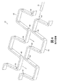
図4は、先行技術のフラットワイヤ式コンベアベルト60の2つのピッチの模式図である。図4から分かるように、フラットワイヤベルト60は、複数のロッド受容アパーチャ64を有する第1ピッチ62を含んでいる。ベルト60は第2ピッチ66も含んでいてもよい。第2ピッチ66も複数のロッド受容アパーチャ68を含んでいる。ロッド受容アパーチャ64がロッド受容アパーチャ68に整列するとき、接続ロッド70を受容するように構成されている実質的に直線状のロッド受容路が第2ピッチ66を横断して延びて形成されている。
FIG. 4 is a schematic diagram of two pitches of a prior art flat
第1ピッチ62および第2ピッチ66を使用してコンベアベルトを組み立てるために、第1ピッチ62は第2ピッチ66に隣接して位置付けられている。第1ピッチ62はさらに、第1ピッチロッド受容アパーチャ64が第2ピッチロッド受容アパーチャ68に整列してロッド受容路を形成するように、第2ピッチ66に係合または相互接続されている。ロッド受容路は接続ロッド70を第1ロッド受容アパーチャ64および第2ピッチロッド受容アパーチャ68の両方に押し通して、第1ピッチ62および第2ピッチ66を連動させることができる。
In order to assemble the conveyor belt using the
別の種類のコンベアベルトはフィンガー式ベルトである。フィンガー式ベルトは、指状の突起が前方および/または後方方向に延びている直線またはジグザグ状の中央横断リブを特徴とするリンクを含んでいてもよい。フィンガーは通例、接続ロッドを挿入できる側方に整列しているロッド穴またはスロットを有している。 Another type of conveyor belt is a finger belt. The finger belt may include links characterized by straight or zigzag central transverse ribs with finger-like protrusions extending in the forward and / or backward direction. The fingers typically have rod holes or slots aligned laterally into which the connecting rod can be inserted.
図5は、フィンガー式ベルト80を示す。図5に図示するように、ベルト80は接続ロッド86を介して第2ピッチ84にヒンジ接続されている第1ピッチ82を含んでいてもよい。ベルト80の各ピッチはジグザグ状の横断リブ88を含んでいてもよい。さらに、各ピッチは互い違いの指状突起90を含んでいてもよく、これは接続ロッド86を受容するように構成されているロッド受容アパーチャ92を含んでいてもよい。
FIG. 5 shows a
いくつかの実施形態では、コンベアベルトピッチのリンクは、接続ロッドが組立状態のコンベアベルトから望ましくない形で外れないように構成されているロッド保持特徴を含んでいてもよい。いくつかの実施形態では、コンベアベルトの左右両方の側方エッジにあるエンドリンクがロッド保持特徴を含んでいてもよい。他の実施形態では、選択したエンドリンクのみにロッド保持特徴を設けていてもよい。例えば、右エンドリンクのみまたは左エンドリンクのみにロッド保持特徴を設けていてもよい。 In some embodiments, the conveyor belt pitch link may include a rod retention feature configured to prevent the connecting rod from undesirably disengaging from the assembled conveyor belt. In some embodiments, end links on both the left and right side edges of the conveyor belt may include rod retention features. In other embodiments, only selected end links may have rod retention features. For example, only the right end link or only the left end link may be provided with a rod retaining feature.
ベルトのすべてのピッチが同じエッジにロッド保持特徴を有していてもよい。ベルトのピッチは、ベルトの右または左のどちらのエッジが保持特徴を含むかに関して交互であってもよい。例えば、第1ピッチはベルトの右エッジにロッド保持特徴を含むエンドリンクを有していてもよく、第2の隣接するピッチは左エッジにロッド保持特徴を含むエンドリンクを有していてもよく、第2ピッチに隣接する第3ピッチは右エッジにロッド保持特徴を含むエンドリンクを含んでいてもよい、など。 All pitches of the belt may have rod retention features on the same edge. The belt pitch may be alternating with respect to whether the right or left edge of the belt contains retention features. For example, the first pitch may have an end link that includes a rod retention feature on the right edge of the belt, and the second adjacent pitch may have an end link that includes a rod retention feature on the left edge. The third pitch adjacent to the second pitch may include an end link including a rod retention feature at the right edge, and so on.
図6は、ロッド220とロッド220に接続されているリンクとを含むコンベアベルト200を示す。リンク210は一般に、2本の実質的に長手方向向きの脚部212、テーパセクション214、および2本の脚部212の間の側方向きのクロス部材216によって形成されている実質的U字形構成を有する。脚部212は、細長いアパーチャなど、ロッド220を受容して、リンク210をロッド220に連動させているアパーチャを含んでいてもよい。
FIG. 6 shows a
リンク210の脚部212は、隣接するリンクのクロス部材216を受容するために離間している。例えば、リンク210bの脚部212は、コンベアベルト200が動いているとき、リンク210aのクロス部材216を受容するように適切に離間している。動作中、リンク210aは、クロス部材216上、脚部212上などのポイントを含め、さまざまな接触ポイントでリンク210bに接触してもよい。
The
本発明の実施形態では、リンク210はリンク210の摩耗を低減するための用意を含んでもよい。リンクの摩耗を低減する方法の一つは、リンクに耐摩耗性材料(wear resistant material)を選択することである。しかし、ある場合には、適した耐摩耗性材料はリンクに望まれる引張り強度(tensile strength)がないことがある。対して、適した引張り強度のある材料は所望の耐摩耗性がないことが多い。
In embodiments of the present invention, link 210 may include provisions for reducing wear of
したがって、リンク210は支持構造物と被覆構造物とから形成されている複合リンクであってもよい。支持構造物は被覆構造物の引張り強度よりも高い引張り強度を有していてもよく、被覆構造物は支持構造物よりも耐摩耗性が高くてもよい。
Therefore, the
この複合リンク構造物の構成は、所望の性能特性を達成するために変えてもよい。いくつかの実施形態では、被覆構造物は支持構造物を一部包囲(enclose)または被覆(cover)していてもよい。例えば、ある場合には、被覆構造物は、接続ロッド、他のリンク、コンベアフレームの固定コンポーネント、および/またはコンベア駆動機構の可動コンポーネントなど、コンベアベルトの他のコンポーネントとの接触を受けるリンクの領域にのみ設けられていてもよい。他の実施形態では、被覆構造物は支持構造物を完全に包囲していてもよい。 The configuration of this composite link structure may be varied to achieve the desired performance characteristics. In some embodiments, the covering structure may partially enclose or cover the support structure. For example, in some cases, the covering structure is a region of a link that is in contact with other components of the conveyor belt, such as connecting rods, other links, stationary components of the conveyor frame, and / or movable components of the conveyor drive mechanism. It may be provided only in. In other embodiments, the covering structure may completely surround the support structure.
被覆構造物は、長手方向の力が接続ロッドから被覆構造物を通して支持構造物に伝わるように、接続ロッドと支持構造物の一部との間に位置付けられていてもよい。すなわち、リンクにかかる長手方向の力は被覆構造物と支持構造物の両方に向けられる。支持構造物はリンクが受ける実質的にすべての引張り力を伝達するように構成されていてもよく、被覆構造物は圧縮力のみを受けるように構成されていてもよい。被覆構造物はリンクが受ける引張り力の少なくとも一部を伝達するように構成されていてもよい。 The covering structure may be positioned between the connecting rod and a portion of the support structure such that longitudinal forces are transferred from the connecting rod through the covering structure to the support structure. That is, the longitudinal force on the link is directed to both the covering structure and the support structure. The support structure may be configured to transmit substantially all of the tensile force experienced by the link, and the covering structure may be configured to receive only the compressive force. The covering structure may be configured to transmit at least a portion of the tensile force experienced by the link.
さらに、リンク上での被覆構造物の位置を変えてよいだけでなく、モジュール式コンベアベルトに複合リンクを含める位置も戦略的に選択してもよい。ターンカーブコンベアベルトは伸長時に曲率半径の中心から離れて配置されているベルトの端部に荷重を掛ける傾向があるのに対し、半径中心に最も近いベルトの内側端部は伸長時に受ける荷重は著しく小さいであろう。したがって、コンベアベルトの外側端部のリンクには引張り強度の高い材料を利用してもよい。例えば、外側エンドリンクには、被覆構造物材料に対して支持構造物材料の高い比率を採用してもよい。同様に、駆動および/または案内機構はしばしばエンドリンクにのみ係合し、ベルトの中央部分に配置されているリンクには係合しないので、エンドリンクは最大の摩耗も受けるであろう。そのため、被覆材料をエンドリンクに、より豊富に、戦略的に使用してもよい。 Furthermore, not only may the position of the covering structure on the link be changed, but the location at which the composite link is included in the modular conveyor belt may also be strategically selected. The turn curve conveyor belt tends to apply a load to the end of the belt that is arranged away from the center of the radius of curvature when extended, whereas the inner end of the belt closest to the radius center receives a significant load when extended. It will be small. Therefore, a material having high tensile strength may be used for the link at the outer end of the conveyor belt. For example, the outer end link may employ a high ratio of support structure material to covering structure material. Similarly, since the drive and / or guide mechanism often only engages the end link and not the link located in the central portion of the belt, the end link will also experience maximum wear. Therefore, the coating material may be used more abundantly and strategically in the end link.
さらに、支持構造物と被覆構造物との相対的なサイズは、所望の特性を達成するために変えてもよい。例えば、支持構造物の体積はリンクの総体積の50パーセントより多くしてもよい。他の実施形態では、支持構造物の体積はリンクの総体積の50パーセント以下にしてもよい。 Furthermore, the relative sizes of the support structure and the covering structure may be varied to achieve the desired properties. For example, the volume of the support structure may be greater than 50 percent of the total volume of the link. In other embodiments, the volume of the support structure may be 50 percent or less of the total volume of the link.
支持構造物および被覆構造物は、前述した相対的特性を有する材料など、あらゆる適した材料から作られていてもよい。例えば、支持構造物および/または被覆構造物は少なくとも一部をスチール、真鍮、アルミニウム、セラミック、繊維強化材料、プラスチック、および/または他の適した材料から作られていてもよい。いくつかの実施形態では、支持構造物は強度を与えるために金属から作られていてもよい。例えば、支持構造物はステンレススチールから作られていてもよい。例えば、コンベアベルトを食品取扱いプロセスに使用する実施形態では、特に支持構造物を被覆材料によって一部のみ被覆しており、そのため食品に露出されるおそれのある実施形態では、支持構造物はステンレススチールから作られていてもよい。ステンレススチールの使用はリンクの腐食を防止し、リンク材料による食品へのマーキングも防止するであろう。 The support structure and the covering structure may be made from any suitable material, such as materials having the relative characteristics described above. For example, the support structure and / or covering structure may be made at least in part from steel, brass, aluminum, ceramic, fiber reinforced material, plastic, and / or other suitable material. In some embodiments, the support structure may be made of metal to provide strength. For example, the support structure may be made from stainless steel. For example, in embodiments where the conveyor belt is used in a food handling process, particularly in embodiments where the support structure is only partially covered by the coating material and thus may be exposed to food, the support structure is stainless steel. May be made from. The use of stainless steel will prevent corrosion of the link and will also prevent food marking with the link material.
前述したように、支持構造物は被覆構造物の引張り強度よりも高い引張り強度を有していてもよく、被覆構造物は支持構造物よりも耐摩耗性が高くてもよい。これらの特性は前述したように適した材料を選択することにより得られるであろう。また、選択する材料を形成するプロセスおよび/またはその材料の処理も、これらの特性の獲得に貢献するであろう。例えば、金属の強度は鍛造などの形成プロセスにより増強してもよく、非金属の強度および/または耐摩耗性はポリマー(プラスチック)の架橋などの形成プロセスによって高めてもよい。また、材料に所望の特性を与えるために、コーティング、熱処理、焼き入れおよび他の処理などの処理を使用してもよい。支持構造物は金属から作られていてもよく、被覆構造物はプラスチックから作られていてもよい。 As described above, the support structure may have a tensile strength higher than that of the covering structure, and the covering structure may have higher wear resistance than the support structure. These properties may be obtained by selecting a suitable material as described above. Also, the process of forming the material of choice and / or treatment of that material will contribute to obtaining these properties. For example, the strength of the metal may be increased by a forming process such as forging, and the strength and / or abrasion resistance of the non-metal may be increased by a forming process such as polymer (plastic) crosslinking. Also, treatments such as coating, heat treatment, quenching and other treatments may be used to impart the desired properties to the material. The support structure may be made from metal and the covering structure may be made from plastic.
被覆構造物は耐摩耗性を与えるためにプラスチック材料から作られていてもよい。被覆構造物は支持構造物を完全に包み込んでいてもよい。他の実施形態では、被覆構造物は支持構造物の選択部分のみを被覆していてもよい。 The covering structure may be made from a plastic material to provide wear resistance. The covering structure may completely enclose the support structure. In other embodiments, the covering structure may cover only selected portions of the support structure.
被覆構造物は、支持構造物をあらゆる適した方法で被覆するように形成されていてもよい。例えば、被覆構造物は内側支持構造物の上にコーティング(例、浸漬コーティング)されていてもよい。他の実施形態では、2つのコンポーネントをコモールド成形してもよい。例えば、予め形成しておいた支持構造物の上に被覆構造物をオーバーモールド成形してもよい。 The covering structure may be configured to cover the support structure in any suitable manner. For example, the covering structure may be coated (eg, dip coated) on the inner support structure. In other embodiments, the two components may be co-molded. For example, the covering structure may be overmolded on a previously formed support structure.
被覆構造物は、機械的インターロック特徴、一体成形されているスナップ特徴、および/または留め具など、他の方法を使用して支持構造物に固着されていてもよい。被覆構造物は支持構造物に取外し可能に連結されていてもよい。 The covering structure may be secured to the support structure using other methods, such as mechanical interlock features, integrally formed snap features, and / or fasteners. The covering structure may be removably connected to the support structure.
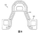
図7〜図10は、複合リンクの実施形態のさまざまな細部を示す。図7および図8に図示するように、リンク210は複合リンク210である。例えば、複合リンク210は支持構造物310と被覆構造物320とを含んでいる。支持構造物320は複合リンク210の形状を確立している輪郭を含んでいる。さらに、支持構造物310はコンベアベルト200(図6に図示)からロッド220を複合リンク210に貫通させるアパーチャ315を含んでいる。
7-10 illustrate various details of the composite link embodiment. As illustrated in FIGS. 7 and 8, the
被覆構造物320はコンベアベルト200からロッド220を受容するアパーチャ325を含み、ロッド220を複合リンク210に貫通させて、複合リンク210と連動させる。アパーチャ315およびアパーチャ325はそれぞれ長手方向に前方位置および後方位置(つまり、リンク脚部の前方端部および後端部)に配設されていてもよい。しかし、いくつかの実施形態では、アパーチャ315および325の相対的な前後の向きが逆であってもよい。複合リンク210は、支持構造物310とロッド220との間の接触を防止するように形成ならびに/もしくは構成されている被覆構造物320の表面でロッド200に接触して連動させるように形成および/または構成されていてもよい。
The covering
いくつかの実施形態では、複合リンクは典型的なリンク構造物を被覆構造物で包み込む(または一部包み込む)ことによって形成されていてもよい。例えば、図6のリンク210の形状は図7の支持構造物310と実質的に同じであることが注目されるだろう。支持構造物と被覆構造物との組み合わせが単一材料から作られている典型的なリンク構造物に匹敵する全体強度を有するように、被覆構造物が追加の強度を備えてもよい。このため、より薄いまたはその他より頑丈でない支持構造物を使用してもよい。
In some embodiments, the composite link may be formed by wrapping (or partially wrapping) a typical link structure with a covering structure. For example, it will be noted that the shape of the
ここで述べるように、複合リンク210は当技術分野で周知のグリッド式コンベアベルト、モジュール式コンベアベルト、および/または他のコンベアベルトによって利用してもよい。アパーチャ325の種類、脚部212もしくはクロス部材216の形状、または複合リンク210自体の形状など、複合リンク210のサイズおよび構成は、コンベアベルトの種類に応じて変えてもよい。例えば、複合リンク210はターンカーブベルト、直進ベルト、スチールロッドを備えるベルト、プラスチックロッドを備えるベルトなどによって利用してもよい。このように、複合リンク210は、支持構造物310および/または被覆構造物320を含めて、特に、その意図される用途に基づいて改造してもよい。
As described herein, the
いくつかの実施形態では、複合リンク210は被覆構造物320によって被覆されている表面でのみロッド220に接触する。例えば、支持構造物310の選択面のみを被覆構造物320でオーバーモールド成形していてもよい。
In some embodiments, the
図9および図10の断面図に図示するように、被覆構造物320のプラスチック面327によって画成されているアパーチャ325は、コンベアベルト220のロッド220を受容し、それに接触するために利用できる唯一の表面である。
9 and 10, the
図9に図示するように、支持構造物310の係合面317はアパーチャ325の少なくとも一部を画成していてもよい。また、これも図9に図示するように、被覆構造物320は係合面317を被覆していてもよく、アパーチャ325の中に挿入される接続ロッドに接触するように構成されている接触面327を設けていてもよい。このように、被覆構造物320は接続ロッドが係合面317に接触するのを防止する。
As illustrated in FIG. 9, the
例えば、スチール製のU字形の金属リンクは適したプラスチック材料で包み込まれていてもよい。金属ロッドと金属リンクとの間にプラスチックが置かれているので、リンクに係合するロッドに形状および支持を与えるスチールは支持されるロッドに接触しない。プラスチックはコンベアベルトの運転中に金属ロッドと金属リンクとの間の摩擦力に起因して金属製リンクが摩耗するのを阻止する。さらに、プラスチックは、他のリンク(金属リンクに隣接するリンクなど)との接触、コンベアベルトを駆動するドラムとの接触、またはコンベアの枠組構造物などリンクに接触するおそれのあるコンベアベルトの他のコンポーネントとの接触に起因して、金属リンクが摩滅するのを阻止する。 For example, a steel U-shaped metal link may be encased in a suitable plastic material. Because the plastic is placed between the metal rod and the metal link, the steel that gives shape and support to the rod engaging the link does not contact the supported rod. The plastic prevents the metal link from being worn due to the frictional force between the metal rod and the metal link during operation of the conveyor belt. In addition, the plastic may contact other links (such as links adjacent to metal links), contact drums that drive the conveyor belt, or other conveyor belts that may contact links such as conveyor frameworks. Prevent wear of metal links due to contact with components.
ここで述べるように、複合リンク210、支持構造物310、および/または被覆構造物320は多様な方法で構成されていてもよい。また、複合リンク210は当技術分野で周知の多様なプロセスを用いて製造または形成してもよい。支持構造物310は鋳造(ダイカスト、遠心鋳造、シェル型鋳造、砂型鋳造など)、塑性変形、シートメタル成形、鍛造、型打ち、機械加工などによって形成してもよい。実質的に形成されたら、金属接続構造物310は所望の形状を得るように、機械加工またはさらなる機械加工をしてもよい。
As described herein, the
被覆構造物320は支持構造物310の上に適したあらゆる方法で形成してもよい。被覆構造物320は支持構造物310を完全に被覆していてもよい。被覆構造物320は、コンベアベルト200の他のコンポーネントに接触する支持構造物310の表面上にのみ成形していてもよい。例えば、被覆構造物320はロッドと接触している表面、別のリンクと接触している表面、ドラムと接触している表面などの上に成形されているプラスチック材料を含んでいてもよい。例えば、アパーチャ325に連動されている被覆構造物を上記で述べているが、被覆構造物は、図11に図示するように、クロス部材216の少なくとも一部を画成している支持構造物の係合面など、別のロッド接触面に設けられていてもよい。
The covering
被覆構造物320の厚さはリンクのセクションによって変わっていてもよい。図11は厚い下側クロス部材セクション705および厚い下側脚部セクション704などの相対的に厚い被覆構造物セクションと、薄いテーパセクション703および薄い上側クロス部材セクション702などの相対的に薄いセクションとを有する複合リンク210を図示している。
The thickness of the covering
ある場合には、複合リンク210はリンク210がコンベアベルト200の他のコンポーネントに接触する箇所に相対的に厚いセクションを有してもよく、リンク210がベルト200の他のコンポーネントに接触しない箇所には比較的薄いセクションを有してもよい。ある場合には、強度を犠牲にすることなく摩耗を防止するために、金属の体積は複合リンク210の一部またはすべてのセクションでプラスチックの体積よりも大きくてもよい。具体的な比率は使用するコンベアベルト200の種類、支持構造物310および/もしくは被覆構造物320として使用される材料の種類、または他の要因によって決める。例えば、比率は、支持構造物310または被覆構造物320のいずれかが故障してもリンクの完全な故障を防ぐ比率など、複合リンク210の一定の破損特性によって決めてもよい。
In some cases, the
ある場合には、厚さは以前に使用したリンクの摩耗に関連する履歴データの分析に基づいて定めてもよい。例えば、分析から、複合リンク210が、例えばロッド220のクロス部材216との接触に起因した摩耗のために、リンク210の他のセクションよりもクロス部材の摩耗に起因して破損する可能性が高いと判断されるかもしれない。分析を用いて、被覆構造物320の下側クロス部材セクション705の厚さは上側クロス部材セクション702の厚さよりも厚くしてもよい。
In some cases, the thickness may be determined based on analysis of historical data related to previously used link wear. For example, from analysis, the
いくつかの実施形態では、支持構造物および被覆構造物のうちの少なくとも一方がリンクの1つの連続したセグメントを構成していてもよい。例えば、被覆構造物は図11に図示するように単一部材の材料であってもよい。 In some embodiments, at least one of the support structure and the covering structure may constitute one continuous segment of the link. For example, the covering structure may be a single piece of material as illustrated in FIG.
しかし、他の実施形態では、支持構造物および被覆構造物のうちの少なくとも一方がリンクの2以上の不連続のセグメントを構成していてもよい。例えば、被覆構造物320は、ロッド220または他のリンクに接触する支持構造物310のセクションを被覆する複数の個別の部材として形成されていてもよい。
However, in other embodiments, at least one of the support structure and the covering structure may constitute two or more discontinuous segments of the link. For example, the covering
図12は、ロッド220を受容しているリンク210のセクションに配置されている複数の被覆構造物320を含む複合リンク210を図示している。例示のために、図12ではロッド220を一部挿入している構成で示している。リンク210の脚部212は被覆構造物320の第1セクション812の被覆を含んでおり、リンク210のクロス部材216は被覆構造物320の第2セクション814の被覆を含んでいる。被覆構造物320はリンク210でロッド220に係合して保持するために利用してもよい。このような構成を以下詳細に述べる。
FIG. 12 illustrates a
図13および図14は、支持構造物310のさまざまな係合面に複数のセクションを有する被覆構造物320を含んでいる複合リンク210を図示している。
13 and 14 illustrate a
図13の複合リンク210は、支持構造物310の脚部212の中にアパーチャを被覆している被覆構造物320のセクション922および924と、支持構造物310のクロス部材216を被覆しているセクション926とを含む。
The
図14の複合リンク210は、クロス部材被覆セクション1034および脚部被覆セクション1032など、支持構造物310の係合面を被覆している被覆構造物320のセクションを含む。
The
いくつかの実施形態では、被覆構造物は受容または保持されている接続ロッドに係合するように構成されている支持構造物の係合面にコンベアベルトのコンポーネントが接触しないように構成していてもよい。この構成により被覆構造物に使用される材料の量を削減することができ、コストと重量を制限するであろう。 In some embodiments, the covering structure is configured so that the conveyor belt components do not contact the engagement surface of the support structure that is configured to engage the receiving or holding connecting rod. Also good. This configuration can reduce the amount of material used in the coating structure and will limit cost and weight.
図15は、受容または保持されているロッド220に係合している支持構造物310の面のみに配置されている被覆構造物320を有する複合リンク210を図示している。被覆構造物320の接触面327は、特に、ロッド220との接続に起因した複合リンク210での摩耗を防止または低減しながら、複合リンク210とロッド220との確実で信頼性のある接続を提供し、ロッド220を受容および保持するように構成または改造されている。被覆構造物320はロッド220を接続することにより支持構造物310上に保持していてもよい。
FIG. 15 illustrates a
支持構造物310は、コンベアベルトの特徴および/または複合リンク210の利用に応じて、多様な構成で形成されていてもよい。図16は、被覆構造物320内に包み込まれている支持構造物310を含む平板構成を有する複合リンク210を図示している。図17は、支持構造物310および複数の被覆構造物320を含む、ラウンドワイヤ構成を有する複合リンク210を図示している。図18は、支持構造物310および複数の被覆構造物320を含み、ロッド220に係合するためにいずれかの端部にフックが設けられている単一の長手部材を有する複合リンク210を図示している。図19は、支持構造物310および複数の被覆構造物320を含み、ロッド220に係合するためにいずれかの端部にループが設けられている単一の長手部材を有する複合リンク210を図示している。当業者には容易に明らかなように、複合リンク210として他の構成、形状、形態などを利用してもよい。例えば、支持構造物310はともに装着または形成されている複数のスチールリンクを含んでもよく、金属とプラスチックの互い違いのリンクなどを含んでもよい。
The
いくつかの実施形態では、支持構造物310は、支持構造物310と被覆構造物320との間の装着を促進または強化する特徴を含んでもよい。
In some embodiments, the
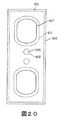
図20は、被覆構造物320のプラグまたは延長部1615を受容することのできる支持構造物310内の装着穴1610を含む複合リンク210を図示している。プラグ1615は被覆構造物320を穴1610を介して支持構造物310に装着しやすくし、利点として特に構造物間の接着強度を高める。当業者には明らかなように、複合リンク210を組み立てるときには他の装着機構を採用してもよい。例えば、被覆構造物320は支持構造物310に機械的に組み付けていてもよい。
FIG. 20 illustrates a
いくつかの実施形態では、被覆構造物320は個別のコンポーネントとして製作され、後で支持構造物310に装着される。図21および図22は個別のコンポーネントとしての被覆構造物320を図示している。
In some embodiments, the covering
図21では、被覆構造物320は支持構造物310の脚部212に連結されるように構成されている脚部連結部分1711と、リンク210のロッド220を受容して保持することのできるロッド保持部分1710とを含む。ロッド220は被覆構造物320を支持構造物310の脚部212に適所で保持してもよい。
In FIG. 21, the covering
図22では、被覆構造物320は個別のコンポーネントとしても形成されており、脚部連結部分1711、ロッド保持部分1710、およびアパーチャ1810を含む。したがって、被覆構造物320は支持構造物310の脚部212に着脱可能としてよい。
In FIG. 22, the covering
いくつかの実施形態では、被覆構造物320はコンベアベルト200の一定のコンポーネントとして利用される部分またはセクションを含む。
In some embodiments, the covering
図23は、ロッド220を受容して保持するために使用されるロッド保持部分1951と、ベルトとコンベアシステムの他のコンポーネントとの摩擦を低減するために使用される接触面部分1953とを含む被覆構造物320を有する複合リンク210を図示している。
FIG. 23 shows a coating that includes a
支持構造物および被覆構造物のうちの少なくとも一方は、リンクに装着されている製品支持面の部分を備えてもよい。例えば、図24はロッド220を受容して保持するために使用されるロッド保持部分2005と、レンガ積み構造など、コンベアベルト200の中央メッシュの部分として作用するメッシュ部分2010とを含む被覆構造物320を有する複合リンク210を図示している。すなわち、複合リンク210はコンベアベルト200のロッド220を互いにおよびリンク210に連結またはその他連動させるように作用する第1部分2005と、コンベアベルトによって運ばれる製品を支持するとともに、運ばれる物品のうちより小さい物がロッド220間に落下しないように構成されているメッシュまたは網として作用する第2部分2010とを含んでいる。第2部分2010は複合リンク210の一部であってもよいが、第2部分2010は支持構造物310のいずれにも設けられていなくてもよい。
At least one of the support structure and the covering structure may comprise a portion of the product support surface attached to the link. For example, FIG. 24 illustrates a
図25は、複合リンク210と、連動ロッド220と、コンベアベルト2100の駆動機構として利用されるスプロケット2110とを含むターンカーブコンベアベルト2100の実施形態を図示している。スプロケット2110は、スプロケット2110が曲がっているとき、リンク210に接触して、リンク210およびロッド220を駆動する力を提供する歯2115を含む。リンク210は支持構造物310と1以上の被覆構造物320とを含む。例えば、リンク210はロッド接触面2121と、上歯接触面2122と、下歯接触面2124とを含む。このように、複合リンク210は支持構造物310をベルト2100のロッド220を連動させるために利用し、プラスチック被覆構造物320を、スプロケット2110および/またはロッド220などのベルト2100の他のコンポーネントと接触するときに支持構造物310を保護するために利用する。
FIG. 25 illustrates an embodiment of a turn
当業者には認識されるように、コンベアベルトはドラム2112によって駆動および/または案内されてもよい。ドラム2112は摩擦ドラムであってもよい。このような実施形態では、ドラム2112の表面は、ドラムと互いに接続していなくてもまたは互いに噛み合っていなくても、ベルトのエッジリンクと係合するだけの十分に高い摩擦係数を有してもよい。スプロケット駆動式およびドラム駆動式のベルトは「Conveyor Belt and System with a Non-collapsing Inside Edge(畳み込まれない内側エッジを備えるコンベアベルトおよびシステム)」と題する特許文献3に詳細に述べられており、その開示全体を参照により本明細書に組み込む。ドラム2112はエラストマー面を有してもよく、または表面の粘着性を高める物質がコーティングされている柔軟な面を有してもよい。このような場合、前述したプラスチック製の被覆面はエッジリンクの摩擦を阻止するだけでなく、エッジリンクとドラム表面との間のより確実な係合も提供するだろう。
As will be appreciated by those skilled in the art, the conveyor belt may be driven and / or guided by
当業者には認識されるように、コンベアベルト200、複合リンク210、被覆構造物320および/または支持構造物310は、ここに具体的に述べていない多様な方法で形成されていてもよい。例えば、被覆構造物320はロッド220を金属リンクに直接係合させてロッド220への装着を容易にするセクションを含んでもよく、または被覆構造物320はボタンヘッド32と支持構造物310との間の摩耗を防止してもよい、など。
As will be appreciated by those skilled in the art, the
当業者には明らかなように、ここで説明する複合リンク210は金属およびプラスチック以外の材料から作られていてもよい。例えば、複合リンク210は、一定のプラスチック、木材、セラミック等など、支持構造物として他の材料を採用してもよい。同様に、複合リンク210は、セラミック、樹脂、布等など、被覆構造物としてさまざまな材料を採用してもよい。
As will be apparent to those skilled in the art, the
ここで述べる特徴は、多くの異なる種類のコンベアベルトで使用してもよく、コンベアベルトの製造を簡素化するための他の技術と組み合わせてもよい。例えば、前述した複合リンクのコンセプトは、ロッド受容アパーチャの正確な整列とロッドの挿入とをともに容易にしながら、さらに挿入されたら接続ロッドを確実に保持するロッド受容アパーチャ整列特徴と組み合わせてもよい。 The features described here may be used with many different types of conveyor belts and may be combined with other techniques to simplify the manufacture of conveyor belts. For example, the composite link concept described above may be combined with a rod receiving aperture alignment feature that facilitates both precise alignment of the rod receiving aperture and insertion of the rod while still securely holding the connecting rod when inserted.
現在の実施形態のさまざまな実施形態を説明してきたが、説明は制限するためのものではなく例示を目的としており、当業者には現在の実施形態の範囲内で他にも多くの実施形態および実施態様が可能であることは明らかであろう。したがって、現在の実施形態は、添付の請求項およびその同等物に照らすことを除き、制限されるべきではない。本開示に述べるあらゆる実施形態の特徴は、本開示で述べる他のあらゆる実施形態に含んでもよい。また、添付の請求項の範囲内でさまざまな修正および変更を行ってもよい。 Although various embodiments of the current embodiment have been described, the description is intended to be illustrative rather than limiting and those skilled in the art will recognize many other embodiments and within the scope of the current embodiment. It will be apparent that embodiments are possible. Accordingly, the present embodiments should not be limited except in light of the appended claims and their equivalents. Features of any embodiment described in this disclosure may be included in any other embodiment described in this disclosure. Various modifications and changes may be made within the scope of the appended claims.
さらに、代表的な実施形態を説明するにあたり、本明細書では方法および/またはプロセスを特定の工程順で提示してきたかもしれない。しかし、方法またはプロセスがここに述べるその特定の工程の順序に依拠していない限り、方法またはプロセスは述べた特定の工程順に制限されるべきではない。当業者であれば分かるように、他の工程順も可能であろう。そのため、本明細書に述べる特定の工程の順序は請求項に対する制限と解釈するべきではない。さらに、方法および/またはプロセスに向けられる請求項は、記載する順序でのその工程の実施に制限されるべきではなく、当業者は順序を変えてもよいことは容易に理解できる。 Further, in describing representative embodiments, methods and / or processes may have been presented herein in a particular sequence of steps. However, unless the method or process relies on that particular order of steps described herein, the method or process should not be limited to the particular steps described. As one skilled in the art will appreciate, other process orders may be possible. As such, the specific order of steps described herein should not be construed as a limitation on the claims. Further, the claims directed to a method and / or process should not be limited to performing the steps in the order described, but can be readily understood by one skilled in the art.
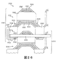
図26は、モジュール式コンベアベルト2500の別の実施形態を示す。図26に図示されるように、コンベアベルト2500は、第1リンク2510を含んでいてもよい第1ピッチ2505を含んでもよい。コンベアベルト2500は、第2リンク2520を含んでいてもよい第2ピッチ2515をさらに含んでもよい。第1リンク2510および第2リンク2520は接続ロッド2522によって接続されて(例、ヒンジ接続されて)いてもよい。
FIG. 26 illustrates another embodiment of a
図26に図示するように、いくつかの実施形態では、隣接するピッチのリンクは実質的に同一の構造を有していてもよい。したがって、第1リンク2510は第2リンク2520と実質的に同一の構造を有していてもよい。そのため、解説を進めるために、第1リンク2510のみを詳細に説明する。
As illustrated in FIG. 26, in some embodiments, adjacent pitch links may have substantially the same structure. Accordingly, the
図26には第1ピッチ2505および第2ピッチ2515はそれぞれ複数のリンクからなる一体構造を有するものとして示されていることに留意するべきである。しかし、各ピッチのリンクは接続ロッドをまたがって側方に配設されている個別のコンポーネントであってもよく、したがって、リンクは互いに接続ロッドを中心に回転してもよい。
It should be noted in FIG. 26 that the first pitch 2505 and the
前述した他の実施形態と同様に、第1リンク2510は、外側脚部2525と、内側脚部2530と、外側脚部2525と内側脚部2530との間のクロス部材2535とを含む実質的にU字形の構成を有していてもよい。第1リンク2510は前方アパーチャ2540と、内側後方アパーチャ2545と、外側端アパーチャ2550とをさらに含んでもよい。アパーチャ2540,2545および2550は、接続ロッド2522を受容するように構成されていてもよい。
Similar to the other embodiments described above, the
第1リンク2510は被覆構造物2560と支持構造物2565とを含んでもよい。被覆構造物2560および支持構造物2565は、前述した被覆構造物および支持構造物と同じまたは同様な特徴および材料を有していてもよい。
The
図26に図示するように、第1リンク2510はエンドリンクであってもよく、被覆構造物および支持構造物のうちの少なくとも一方によって形成されているロッド保持特徴を含んでもよい。例えば、図26に図示するように、第1リンク2510は、完全に挿入されたら接続ロッド2522の自由端を収容するように構成されているロッド用凹部2555を含んでもよい。ロッド2522を凹部2555の中に保持するとともに、ロッド2522が外側端アパーチャ2550から抜けるのを防止するために、第1リンク2510は外側端アパーチャ2550付近にロッド保持用隆起2570を含んでもよい。ロッド保持用隆起2570は少なくとも一部が被覆構造物2560によって画成されていてもよい。ロッド保持用隆起2570は接続ロッドの長手方向の並進を阻止するように構成されている側方向きの隆起を含んでいてもよい。
As illustrated in FIG. 26, the
図27は第1リンク2510の斜視切開部分断面図である。図27では、第1リンク2510の内側端部は省略した態様で図示されている。しかし、第1リンク2510は独立した個別リンクとして実質的に同様な形態を有していてもよい。
FIG. 27 is a perspective cut-away partial cross-sectional view of the
図27はロッド保持用隆起2570に関して追加の細部も示している。いくつかの実施形態では、ロッド保持用隆起は戻り止めの形態を有していてもよい。例えば、図27に図示するように、ロッド保持用隆起2570は傾斜した前壁2575と傾斜した後壁2580とを含んでもよい。図27に図示するように、前壁2575および後壁2580は凹曲度を有していてもよい。他の実施形態では、前壁2575および/または後壁2580は比較的平坦な構成または凸状構成を有していてもよい。さらに、隆起2570は実質的に半円の断面形状を有していてもよい。また、図27に図示するように、隆起2570は端壁2585で終端していてもよい。
FIG. 27 also shows additional details regarding the
内側アパーチャ2545および外側アパーチャ2550は、図27に図示するように、長手方向に細長い/スロット付き構成を有していてもよい。この構成は挿入されている接続ロッドをアパーチャ2545および2550の中で長手方向に並進させることができるであろう。接続ロッドはロッド抜き差し位置でアパーチャ2550および内側アパーチャ2545の前方端部に挿入してもよい。接続ロッドを第1リンク2510に固定するために、接続ロッドをさらにロッド保持用隆起2570を超えて、内側アパーチャ2545の後方端部まで長手方向に並進してもよい。内側アパーチャ2545は、例えば内側リンク脚部2530内の中央開口のために、内側開口2546および外側開口2547などの2つのコンポーネントを有していてもよいことを留意すべきである。
図28は、第1リンク2510の斜視切開拡大断面図を示す。図28に図示するように、外側端部アパーチャ2550は湾曲壁2551によって画成されていてもよい。さらに、凹部2555は、ロッド保持用隆起2570によって凹部2555に保持されるときに接続ロッドが側方方向に動くのを防止する端壁2556によって少なくとも一部が画成されていてもよい。また、図28にさらに図示されるように、第1リンク2510は外側リンク脚部2525に中央開口2557を含んでもよい。このような中央開口は被覆構造物2560および/または支持構造物2565に使用される材料の量を減少できるであろう。
FIG. 28 is a perspective cut-away enlarged cross-sectional view of the
あるいは追加で、ロッド保持特徴の他の構成も実施してもよい。例えば、ロッド保持特徴はロッドを第1リンクに堅く接続する機械的アタッチメントを含んでもよい。保護の利点に加えて、被覆構造物320にロッド220を保持する特徴を組み込むことは、特に、ロッド220をリンク210に溶接する必要性をなくすであろう。当該リンクロッド保持特徴の実施形態は、「Conveyor Belt and Method of Assembly(コンベアベルトおよび組立方法)」と題する特許文献4により完全に開示されている。追加のロッド保持特徴は、それぞれ2011年12月6日に出願され、「Conveyor Belt Link with Rod Retaining Feature(ロッド保持特徴を備えるコンベアベルトリンク)」と題する、現在米国出願番号第13/311,773号、第13/311,797号、第13/311,882号、第13/311,888号および第13/311,900号である特許文献5、特許文献6、特許文献7、特許文献8および特許文献9に開示されている。本段落に述べる特許文書はそれぞれ参照によりその全体を本明細書に組み込む。
Alternatively, other configurations of rod retention features may be implemented in addition. For example, the rod retention feature may include a mechanical attachment that rigidly connects the rod to the first link. In addition to the benefit of protection, incorporating features that retain the
本発明のさまざまな実施形態を説明してきたが、説明は制限するためのものではなく例示を目的としており、当業者には本発明の範囲内で他にも多くの実施形態および実施態様が可能であることは明らかであろう。したがって、本発明は添付の請求項およびその同等物に照らすことを除き、制限されるべきではない。さらに、開示される実施形態のいずれの特徴も、開示される他の実施形態のいずれでも実施することができる。また、添付の請求項の範囲内でさまざまな修正および変更を行ってもよい。 Although various embodiments of the present invention have been described, the description is intended to be illustrative rather than limiting and many other embodiments and implementations are possible to those skilled in the art within the scope of the present invention. It will be clear. Accordingly, the invention should not be limited except in light of the attached claims and their equivalents. Moreover, any feature of the disclosed embodiments can be implemented in any of the other disclosed embodiments. Various modifications and changes may be made within the scope of the appended claims.
Claims (38)
前記支持構造物の少なくとも一部を被覆している被覆構造物(bearing structure)とを備えており、
前記支持構造物は前記被覆構造物よりも高い引張り強度を有しており、
前記被覆構造物は前記支持構造物よりも耐摩耗性が高く、前記被覆構造物は、前記支持構造物の係合面の付近に配置されているロッド接触面を有しており、前記ロッド接触面は接続ロッドに接触するように構成されている、モジュール式コンベアベルトのリンク。 A supporting structure;
A covering structure covering at least a part of the support structure,
The support structure has a higher tensile strength than the covering structure;
The coating structure is rather high wear resistance than the support structure, wherein the coating structure has a rod contacting surface disposed in the vicinity of the engaging surface of said support structure, said rod A modular conveyor belt link , the contact surface being configured to contact the connecting rod .
第1材料から作られており、複合リンクの形状を確立している輪郭を有する支持構造物と、
第2材料から作られており、少なくとも1つのコンベアベルトのコンポーネントに係合するように構成されている前記支持構造物の係合面に配置されている被覆構造物とを備え、
前記被覆構造物は前記少なくとも1つのコンベアベルトのコンポーネントが前記支持構造物の前記係合面に接触するのを防止するように構成されており、前記リンクは、前方端部および後端部にロッドアパーチャをそれぞれ有する2本の実質的に長手方向(コンベアベルトの中心線に沿った方向をいう。)向きの脚部と、前記2本の脚部の間の側方向きのクロス部材とから形成されている実質的にU字形の構成を有し、前記支持構造物の前記係合面は、前記クロス部材の少なくとも一部を画成し、前記被覆構造物は前記支持構造物の前記係合面の付近に配置されているロッド接触面を含んでおり、前記ロッド接触面は前記接続ロッドに接触するように構成されている、モジュール式コンベアベルトのリンク。 A modular conveyor belt link comprising elongated connecting rods, the link comprising:
A support structure made of a first material and having a contour establishing the shape of the composite link;
A covering structure made of a second material and disposed on an engagement surface of the support structure configured to engage a component of at least one conveyor belt;
The covering structure is configured to prevent a component of the at least one conveyor belt from contacting the engagement surface of the support structure, and the link is a rod at a front end and a rear end. Formed from two substantially longitudinal leg portions (referred to as directions along the center line of the conveyor belt) each having an aperture, and a lateral cross member between the two leg portions. Wherein the engagement surface of the support structure defines at least a portion of the cross member, and the covering structure is the engagement of the support structure. A modular conveyor belt link comprising a rod contact surface disposed in the vicinity of a surface, wherein the rod contact surface is configured to contact the connecting rod .
前記第1リンクと前記第2リンクとを互いにヒンジ式に装着するように構成されている細長い接続ロッドとを備えるモジュール式コンベアベルトであって、
前記第1リンクは支持構造物と前記支持構造物の少なくとも一部を被覆している被覆構造物とを含んでおり、前記支持構造物は前記被覆構造物よりも高い引張り強度を有し、前記被覆構造物は前記支持構造物よりも耐摩耗性が高く、前記被覆構造物は前記支持構造物が前記接続ロッド、隣接リンク、コンベアのフレームの固定部分、または前記コンベアの駆動コンポーネントのうちの少なくとも1つに接触するのを防止する、モジュール式コンベアベルト。 At least a first link and a second link;
A modular conveyor belt comprising an elongated connecting rod configured to hingeably attach the first link and the second link to each other;
The first link includes a supporting structure and a covering structure covering at least a part of the supporting structure, and the supporting structure has a higher tensile strength than the covering structure, coating structure is rather high wear resistance than the support structure, wherein the coating structure is the support structure is the connecting rod, adjacent link, the fixed portion of the conveyor frame or of the drive component of said conveyor, A modular conveyor belt that prevents contact with at least one .
Applications Claiming Priority (3)
| Application Number | Priority Date | Filing Date | Title |
|---|---|---|---|
| US13/472,096 | 2012-05-15 | ||
| US13/472,096 US8985318B2 (en) | 2012-05-15 | 2012-05-15 | Conveyor belt with composite link |
| PCT/US2013/040838 WO2013173263A2 (en) | 2012-05-15 | 2013-05-14 | Conveyor belt with composite link |
Publications (2)
| Publication Number | Publication Date |
|---|---|
| JP2015516349A JP2015516349A (en) | 2015-06-11 |
| JP6156887B2 true JP6156887B2 (en) | 2017-07-05 |
Family
ID=49580398
Family Applications (1)
| Application Number | Title | Priority Date | Filing Date |
|---|---|---|---|
| JP2015512729A Active JP6156887B2 (en) | 2012-05-15 | 2013-05-14 | Composite link and conveyor belt having the same |
Country Status (8)
| Country | Link |
|---|---|
| US (1) | US8985318B2 (en) |
| EP (1) | EP2850021A4 (en) |
| JP (1) | JP6156887B2 (en) |
| KR (1) | KR101804010B1 (en) |
| BR (1) | BR112014028435B1 (en) |
| CA (1) | CA2871775C (en) |
| MX (1) | MX349028B (en) |
| WO (1) | WO2013173263A2 (en) |
Cited By (1)
| Publication number | Priority date | Publication date | Assignee | Title |
|---|---|---|---|---|
| JP7456617B2 (en) | 2020-09-30 | 2024-03-27 | 株式会社フロンティアエンジニアリング | Food and drink manufacturing equipment |
Families Citing this family (8)
| Publication number | Priority date | Publication date | Assignee | Title |
|---|---|---|---|---|
| EP3429945A4 (en) * | 2016-03-15 | 2019-11-13 | Cambridge International, Inc. | High temperature conveyor belt |
| US10577183B2 (en) * | 2016-09-14 | 2020-03-03 | Cambridge International, Inc. | Edge drive mesh overlay conveyor belt |
| EP3369681B1 (en) | 2017-03-03 | 2020-12-30 | Cambridge International, Inc. | Direct edge drive conveyor belt |
| EP3746379A4 (en) * | 2018-01-30 | 2021-11-03 | Cambridge International, Inc. | Splice system for conveyor belt |
| IT201900006102A1 (en) * | 2019-04-18 | 2020-10-18 | Incobra S R L | CONNECTION MESH FOR SUPPORT ELEMENTS FOR CONVEYOR BELTS, SUPPORT ELEMENTS FOR CONVEYOR BELTS, METHOD FOR MAKING THE CONNECTION MESH AND SUPPORT ELEMENT |
| EP3966135A4 (en) | 2019-05-08 | 2023-01-18 | Cambridge International, Inc. | Direct drive spiral conveyor belt systems and methods |
| WO2021041640A1 (en) | 2019-08-29 | 2021-03-04 | Cambridge International, Inc. | Active direct drive spiral conveyor belt systems and methods |
| DK202270583A1 (en) * | 2022-12-06 | 2024-07-01 | Ammeraal Beltech Modular As | High Stiffness Belt |
Family Cites Families (33)
| Publication number | Priority date | Publication date | Assignee | Title |
|---|---|---|---|---|
| US3646752A (en) | 1970-09-28 | 1972-03-07 | Conveyor Specialties Co | Plastic encased metal ribbed flexible conveyor chain |
| BE787659A (en) | 1971-06-25 | 1973-02-19 | Baychem Corp | TRACK SKATE, PREFERRED IN SYNTHETIC MATERIAL. |
| US4078655A (en) * | 1977-02-25 | 1978-03-14 | Ashworth Bros., Inc. | Small radius conveyor belt and conveying system |
| JPS6121631Y2 (en) | 1979-04-14 | 1986-06-28 | ||
| IT8134921V0 (en) | 1981-12-22 | 1981-12-22 | Marbett S N C Di Mariani Betta | CONVEYOR CHAIN WITH ANTI-WEAR COATING |
| NL189245C (en) * | 1983-01-14 | 1993-02-16 | Tsubakimoto Chain Co | TRANSPORT CHAIN WITH FLAT TOP. |
| JPS59158714A (en) * | 1983-02-24 | 1984-09-08 | Tsubakimoto Chain Co | Table conveyer chain |
| US4846339A (en) | 1987-03-11 | 1989-07-11 | Ashworth Bros., Inc. | Flat wire conveyor with differential pitch |
| US5141102A (en) | 1987-08-10 | 1992-08-25 | Ashworth Bros., Inc. | Conveyor belt and system with a non-collapsing inside edge |
| SE460355B (en) | 1988-01-08 | 1989-10-02 | Mats Ejvin Wahren | TRANSPORT CHAIN |
| US5088920A (en) | 1990-11-30 | 1992-02-18 | Glasstech, Inc. | Drive mechanism for glass sheet roller conveyor of furnace |
| US5197591A (en) * | 1992-02-11 | 1993-03-30 | Ashworth Bros., Inc. | Replaceable snap-on modular overlay for rod and link turn-curve conveyor belts |
| JPH0743044Y2 (en) * | 1991-10-22 | 1995-10-04 | 大和製罐株式会社 | Conveyor belt for can body transportation in can body surface treatment equipment |
| US5439097A (en) * | 1991-10-29 | 1995-08-08 | Tsubakimoto Chain Co. | Link for conveyor chains |
| US5271491A (en) * | 1993-02-18 | 1993-12-21 | Guy Irwin | Bi-directional short radius turn conveyor belt |
| DE69510423T2 (en) | 1994-04-15 | 2000-02-24 | Jorgen Draebel | CONVEYOR CHAIN WITH A BASE CONSTRUCTED FROM CHAIN LINKS CROSS TO THE LENGTH DIRECTION OF THIS CONVEYOR CHAIN |
| DE29612735U1 (en) | 1996-07-23 | 1996-09-12 | Wolf - Montage - Automationsanlagen + Sondermaschinen - GmbH, 97264 Helmstadt | Transport chain |
| JPH10338326A (en) | 1997-06-09 | 1998-12-22 | Kobayashi Seisakusho:Kk | Plastic conveyor belt and conveyor device using it |
| US5954188A (en) | 1997-06-12 | 1999-09-21 | Ashworth Bros., Inc. | Conveyor belt |
| US6161685A (en) | 1999-03-26 | 2000-12-19 | Rexnord Corporation | Thermoplastic chain link for a modular conveyor chain |
| US6360882B1 (en) * | 1999-06-18 | 2002-03-26 | Cambridge, Inc. | Conveyor belt and method of making the same |
| US6615979B2 (en) * | 2001-08-06 | 2003-09-09 | Ashworth Bros., Inc. | Conveyor belt and method of assembly |
| ES2253655T3 (en) * | 2002-10-11 | 2006-06-01 | Habasit Ag | TRANSPORTER TAPE MODULES WITH HIGH FRICTION SURFACE. |
| NL1024361C2 (en) * | 2003-09-23 | 2005-03-24 | Rexnord Flattop Europe Bv | Modular transport mat. |
| US7073662B2 (en) | 2004-02-20 | 2006-07-11 | Ashworth Bros., Inc. | Conveyor belt and method of assembly |
| US20060006669A1 (en) * | 2004-07-08 | 2006-01-12 | James Nelsen | Vehicle latch apparatus and method |
| US7530454B2 (en) * | 2005-11-08 | 2009-05-12 | Ashworth Bros. Inc. | Conveyor belt |
| NL1030625C2 (en) * | 2005-12-08 | 2007-06-11 | Rexnord Flattop Europe Bv | Modular transport mat and transport mat module. |
| JP2009532308A (en) * | 2006-04-03 | 2009-09-10 | スパン テック エルエルシー | Product conveying component with powder coating and method related thereto |
| US7802676B2 (en) * | 2007-06-22 | 2010-09-28 | Habasit Ag | Conveyor belt module with high friction conveying surface |
| ITBO20070696A1 (en) * | 2007-10-17 | 2009-04-18 | Gd Spa | TRANSFER DEVICE INTO SYSTEMS FOR SMOKE ITEMS. |
| US20110284347A1 (en) * | 2009-01-12 | 2011-11-24 | Laitram, L.L.C. | Metal-fused plastic conveyor belt components and methods of making |
| US8522961B2 (en) | 2010-08-19 | 2013-09-03 | Laitram, L.L.C. | Two-material conveyor belt module |
-
2012
- 2012-05-15 US US13/472,096 patent/US8985318B2/en active Active
-
2013
- 2013-05-14 CA CA2871775A patent/CA2871775C/en active Active
- 2013-05-14 BR BR112014028435-0A patent/BR112014028435B1/en active IP Right Grant
- 2013-05-14 EP EP13790441.3A patent/EP2850021A4/en active Pending
- 2013-05-14 KR KR1020147033869A patent/KR101804010B1/en active IP Right Grant
- 2013-05-14 JP JP2015512729A patent/JP6156887B2/en active Active
- 2013-05-14 MX MX2014013869A patent/MX349028B/en active IP Right Grant
- 2013-05-14 WO PCT/US2013/040838 patent/WO2013173263A2/en active Application Filing
Cited By (1)
| Publication number | Priority date | Publication date | Assignee | Title |
|---|---|---|---|---|
| JP7456617B2 (en) | 2020-09-30 | 2024-03-27 | 株式会社フロンティアエンジニアリング | Food and drink manufacturing equipment |
Also Published As
| Publication number | Publication date |
|---|---|
| WO2013173263A3 (en) | 2014-04-03 |
| US20130306446A1 (en) | 2013-11-21 |
| BR112014028435A2 (en) | 2017-06-27 |
| WO2013173263A2 (en) | 2013-11-21 |
| JP2015516349A (en) | 2015-06-11 |
| CA2871775A1 (en) | 2013-11-21 |
| MX349028B (en) | 2017-07-05 |
| CA2871775C (en) | 2017-08-15 |
| EP2850021A2 (en) | 2015-03-25 |
| US8985318B2 (en) | 2015-03-24 |
| KR20150027746A (en) | 2015-03-12 |
| MX2014013869A (en) | 2015-02-12 |
| EP2850021A4 (en) | 2016-01-20 |
| BR112014028435B1 (en) | 2020-11-10 |
| KR101804010B1 (en) | 2017-12-01 |
Similar Documents
| Publication | Publication Date | Title |
|---|---|---|
| JP6156887B2 (en) | Composite link and conveyor belt having the same | |
| JP6215923B2 (en) | Conveyor belt link with wear-resistant part | |
| EP2871144B1 (en) | Variable spaced conveyor belt with clinched rod ends | |
| CA2072910C (en) | Modular plastic turn belt conveyor system, module, belt and drive therefor | |
| EP3369681B1 (en) | Direct edge drive conveyor belt | |
| JP5275818B2 (en) | Conveyor with trough-type low friction positive drive belt | |
| US8844713B2 (en) | Conveyor belt link with wear resistance features | |
| EP1473260A1 (en) | Modular conveyor and conveyor links | |
| US20060124437A1 (en) | Modular conveyor belt with unique link capture means | |
| US8607967B2 (en) | Conveyor belt link with rod retaining feature | |
| EP3168174B1 (en) | Modular eye link conveyor belt | |
| JP4184261B2 (en) | Modular belt link | |
| EP2195264B1 (en) | Conveyors and transmission belts | |
| US8636141B2 (en) | Conveyor belt link with rod retaining feature | |
| EP2374739B1 (en) | Restrictor clip | |
| JP5986684B2 (en) | Link member having a curved receiving surface | |
| CA2488986C (en) | Conveyor belt | |
| JP2005524589A (en) | Conveyor belt | |
| US20130140152A1 (en) | Conveyor Belt Link With Rod Retaining Feature | |
| FR2490198A1 (en) | CONVEYOR COMPRISING A FLEXIBLE CONTINUOUS DRAWING DEVICE IN SEVERAL DIRECTIONS |
Legal Events
| Date | Code | Title | Description |
|---|---|---|---|
| A621 | Written request for application examination |
Free format text: JAPANESE INTERMEDIATE CODE: A621 Effective date: 20150420 |
|
| A131 | Notification of reasons for refusal |
Free format text: JAPANESE INTERMEDIATE CODE: A131 Effective date: 20160623 |
|
| A601 | Written request for extension of time |
Free format text: JAPANESE INTERMEDIATE CODE: A601 Effective date: 20160921 |
|
| A521 | Request for written amendment filed |
Free format text: JAPANESE INTERMEDIATE CODE: A523 Effective date: 20161124 |
|
| TRDD | Decision of grant or rejection written | ||
| A01 | Written decision to grant a patent or to grant a registration (utility model) |
Free format text: JAPANESE INTERMEDIATE CODE: A01 Effective date: 20170511 |
|
| A61 | First payment of annual fees (during grant procedure) |
Free format text: JAPANESE INTERMEDIATE CODE: A61 Effective date: 20170601 |
|
| R150 | Certificate of patent or registration of utility model |
Ref document number: 6156887 Country of ref document: JP Free format text: JAPANESE INTERMEDIATE CODE: R150 |
|
| R250 | Receipt of annual fees |
Free format text: JAPANESE INTERMEDIATE CODE: R250 |
|
| R250 | Receipt of annual fees |
Free format text: JAPANESE INTERMEDIATE CODE: R250 |
|
| R250 | Receipt of annual fees |
Free format text: JAPANESE INTERMEDIATE CODE: R250 |
|
| R250 | Receipt of annual fees |
Free format text: JAPANESE INTERMEDIATE CODE: R250 |
|
| R250 | Receipt of annual fees |
Free format text: JAPANESE INTERMEDIATE CODE: R250 |