EP3326936A1 - Package for rod-shaped tobacco articles - Google Patents
Package for rod-shaped tobacco articles Download PDFInfo
- Publication number
- EP3326936A1 EP3326936A1 EP15898901.2A EP15898901A EP3326936A1 EP 3326936 A1 EP3326936 A1 EP 3326936A1 EP 15898901 A EP15898901 A EP 15898901A EP 3326936 A1 EP3326936 A1 EP 3326936A1
- Authority
- EP
- European Patent Office
- Prior art keywords
- package
- partition unit
- rod
- wall
- horizontal partition
- Prior art date
- Legal status (The legal status is an assumption and is not a legal conclusion. Google has not performed a legal analysis and makes no representation as to the accuracy of the status listed.)
- Withdrawn
Links
- 241000208125 Nicotiana Species 0.000 title claims abstract description 156
- 235000002637 Nicotiana tabacum Nutrition 0.000 title claims abstract description 156
- 238000005192 partition Methods 0.000 claims abstract description 376
- 230000006866 deterioration Effects 0.000 claims description 7
- 230000000391 smoking effect Effects 0.000 description 199
- OKTJSMMVPCPJKN-UHFFFAOYSA-N Carbon Chemical compound [C] OKTJSMMVPCPJKN-UHFFFAOYSA-N 0.000 description 61
- 229910052799 carbon Inorganic materials 0.000 description 53
- 238000010586 diagram Methods 0.000 description 19
- 229910003460 diamond Inorganic materials 0.000 description 18
- 239000010432 diamond Substances 0.000 description 18
- 239000000443 aerosol Substances 0.000 description 15
- 239000000463 material Substances 0.000 description 13
- XAGFODPZIPBFFR-UHFFFAOYSA-N aluminium Chemical compound [Al] XAGFODPZIPBFFR-UHFFFAOYSA-N 0.000 description 10
- 229910052782 aluminium Inorganic materials 0.000 description 10
- 238000000034 method Methods 0.000 description 9
- 230000004048 modification Effects 0.000 description 9
- 238000012986 modification Methods 0.000 description 9
- 239000000796 flavoring agent Substances 0.000 description 5
- 235000019634 flavors Nutrition 0.000 description 5
- 230000000694 effects Effects 0.000 description 4
- 239000011230 binding agent Substances 0.000 description 3
- 235000019504 cigarettes Nutrition 0.000 description 3
- 239000002245 particle Substances 0.000 description 3
- 239000011347 resin Substances 0.000 description 3
- 229920005989 resin Polymers 0.000 description 3
- 239000000654 additive Substances 0.000 description 2
- 230000000996 additive effect Effects 0.000 description 2
- 230000007423 decrease Effects 0.000 description 2
- 238000010438 heat treatment Methods 0.000 description 2
- 239000000203 mixture Substances 0.000 description 2
- XLYOFNOQVPJJNP-UHFFFAOYSA-N water Substances O XLYOFNOQVPJJNP-UHFFFAOYSA-N 0.000 description 2
- 239000010425 asbestos Substances 0.000 description 1
- 235000019506 cigar Nutrition 0.000 description 1
- 239000002994 raw material Substances 0.000 description 1
- 229910052895 riebeckite Inorganic materials 0.000 description 1
- 238000007790 scraping Methods 0.000 description 1
- 239000000779 smoke Substances 0.000 description 1
- 238000000638 solvent extraction Methods 0.000 description 1
- 229910001220 stainless steel Inorganic materials 0.000 description 1
- 239000010935 stainless steel Substances 0.000 description 1
Images








Classifications
-
- B—PERFORMING OPERATIONS; TRANSPORTING
- B65—CONVEYING; PACKING; STORING; HANDLING THIN OR FILAMENTARY MATERIAL
- B65D—CONTAINERS FOR STORAGE OR TRANSPORT OF ARTICLES OR MATERIALS, e.g. BAGS, BARRELS, BOTTLES, BOXES, CANS, CARTONS, CRATES, DRUMS, JARS, TANKS, HOPPERS, FORWARDING CONTAINERS; ACCESSORIES, CLOSURES, OR FITTINGS THEREFOR; PACKAGING ELEMENTS; PACKAGES
- B65D85/00—Containers, packaging elements or packages, specially adapted for particular articles or materials
- B65D85/07—Containers, packaging elements or packages, specially adapted for particular articles or materials for compressible or flexible articles
- B65D85/08—Containers, packaging elements or packages, specially adapted for particular articles or materials for compressible or flexible articles rod-shaped or tubular
- B65D85/10—Containers, packaging elements or packages, specially adapted for particular articles or materials for compressible or flexible articles rod-shaped or tubular for cigarettes
- B65D85/1036—Containers formed by erecting a rigid or semi-rigid blank
- B65D85/1045—Containers formed by erecting a rigid or semi-rigid blank having a cap-like lid hinged to an edge
- B65D85/1048—Containers formed by erecting a rigid or semi-rigid blank having a cap-like lid hinged to an edge characterized by the shape of the container
-
- A—HUMAN NECESSITIES
- A24—TOBACCO; CIGARS; CIGARETTES; SIMULATED SMOKING DEVICES; SMOKERS' REQUISITES
- A24F—SMOKERS' REQUISITES; MATCH BOXES; SIMULATED SMOKING DEVICES
- A24F15/00—Receptacles or boxes specially adapted for cigars, cigarettes, simulated smoking devices or cigarettes therefor
- A24F15/01—Receptacles or boxes specially adapted for cigars, cigarettes, simulated smoking devices or cigarettes therefor specially adapted for simulated smoking devices or cigarettes therefor
-
- A—HUMAN NECESSITIES
- A24—TOBACCO; CIGARS; CIGARETTES; SIMULATED SMOKING DEVICES; SMOKERS' REQUISITES
- A24F—SMOKERS' REQUISITES; MATCH BOXES; SIMULATED SMOKING DEVICES
- A24F15/00—Receptacles or boxes specially adapted for cigars, cigarettes, simulated smoking devices or cigarettes therefor
- A24F15/20—Receptacles or boxes specially adapted for cigars, cigarettes, simulated smoking devices or cigarettes therefor with separate compartments for each cigar or cigarette
-
- B—PERFORMING OPERATIONS; TRANSPORTING
- B65—CONVEYING; PACKING; STORING; HANDLING THIN OR FILAMENTARY MATERIAL
- B65D—CONTAINERS FOR STORAGE OR TRANSPORT OF ARTICLES OR MATERIALS, e.g. BAGS, BARRELS, BOTTLES, BOXES, CANS, CARTONS, CRATES, DRUMS, JARS, TANKS, HOPPERS, FORWARDING CONTAINERS; ACCESSORIES, CLOSURES, OR FITTINGS THEREFOR; PACKAGING ELEMENTS; PACKAGES
- B65D5/00—Rigid or semi-rigid containers of polygonal cross-section, e.g. boxes, cartons or trays, formed by folding or erecting one or more blanks made of paper
- B65D5/42—Details of containers or of foldable or erectable container blanks
- B65D5/44—Integral, inserted or attached portions forming internal or external fittings
- B65D5/48—Partitions
- B65D5/48024—Partitions inserted
- B65D5/48026—Squaring or like elements, e.g. honeycomb element, i.e. at least four not aligned compartments
- B65D5/48038—Strips crossing each other
-
- B—PERFORMING OPERATIONS; TRANSPORTING
- B65—CONVEYING; PACKING; STORING; HANDLING THIN OR FILAMENTARY MATERIAL
- B65D—CONTAINERS FOR STORAGE OR TRANSPORT OF ARTICLES OR MATERIALS, e.g. BAGS, BARRELS, BOTTLES, BOXES, CANS, CARTONS, CRATES, DRUMS, JARS, TANKS, HOPPERS, FORWARDING CONTAINERS; ACCESSORIES, CLOSURES, OR FITTINGS THEREFOR; PACKAGING ELEMENTS; PACKAGES
- B65D5/00—Rigid or semi-rigid containers of polygonal cross-section, e.g. boxes, cartons or trays, formed by folding or erecting one or more blanks made of paper
- B65D5/42—Details of containers or of foldable or erectable container blanks
- B65D5/44—Integral, inserted or attached portions forming internal or external fittings
- B65D5/50—Internal supporting or protecting elements for contents
- B65D5/5028—Elements formed separately from the container body
- B65D5/5035—Paper elements
- B65D5/5059—Paper panels presenting one or more openings or recesses in wich at least a part of the contents are located
-
- B—PERFORMING OPERATIONS; TRANSPORTING
- B65—CONVEYING; PACKING; STORING; HANDLING THIN OR FILAMENTARY MATERIAL
- B65D—CONTAINERS FOR STORAGE OR TRANSPORT OF ARTICLES OR MATERIALS, e.g. BAGS, BARRELS, BOTTLES, BOXES, CANS, CARTONS, CRATES, DRUMS, JARS, TANKS, HOPPERS, FORWARDING CONTAINERS; ACCESSORIES, CLOSURES, OR FITTINGS THEREFOR; PACKAGING ELEMENTS; PACKAGES
- B65D85/00—Containers, packaging elements or packages, specially adapted for particular articles or materials
- B65D85/07—Containers, packaging elements or packages, specially adapted for particular articles or materials for compressible or flexible articles
- B65D85/08—Containers, packaging elements or packages, specially adapted for particular articles or materials for compressible or flexible articles rod-shaped or tubular
- B65D85/10—Containers, packaging elements or packages, specially adapted for particular articles or materials for compressible or flexible articles rod-shaped or tubular for cigarettes
- B65D85/1036—Containers formed by erecting a rigid or semi-rigid blank
- B65D85/1045—Containers formed by erecting a rigid or semi-rigid blank having a cap-like lid hinged to an edge
-
- B—PERFORMING OPERATIONS; TRANSPORTING
- B65—CONVEYING; PACKING; STORING; HANDLING THIN OR FILAMENTARY MATERIAL
- B65D—CONTAINERS FOR STORAGE OR TRANSPORT OF ARTICLES OR MATERIALS, e.g. BAGS, BARRELS, BOTTLES, BOXES, CANS, CARTONS, CRATES, DRUMS, JARS, TANKS, HOPPERS, FORWARDING CONTAINERS; ACCESSORIES, CLOSURES, OR FITTINGS THEREFOR; PACKAGING ELEMENTS; PACKAGES
- B65D85/00—Containers, packaging elements or packages, specially adapted for particular articles or materials
- B65D85/07—Containers, packaging elements or packages, specially adapted for particular articles or materials for compressible or flexible articles
- B65D85/08—Containers, packaging elements or packages, specially adapted for particular articles or materials for compressible or flexible articles rod-shaped or tubular
- B65D85/10—Containers, packaging elements or packages, specially adapted for particular articles or materials for compressible or flexible articles rod-shaped or tubular for cigarettes
- B65D85/1081—Inserts or accessories added or joined to the container, e.g. coins, pens, cards, spacers
Definitions
- the present invention relates to a package of a rod-like tobacco article.
- a package (wrapping) of a rod-like tobacco article that stores rod-like tobacco articles has been widely known.
- An example of the package is a hinge-lid package.
- a hinge-lid package is a box package including a lid part called a lid that is openably connected to an outer box.
- Patent document 1 describes a technique of partitioning a main body of a package.
- Patent documents 2 and 3 disclose a tobacco package having a function of storing tobacco butts, and a tobacco package having an ashtray function.
- Patent documents 4 and 5 disclose packages having digesting functions.
- Patent document 6 discloses a fire extinguishing device for tobaccos.
- a known non-combusted smoking article includes a heat source which is a heating member attached to the tip end, and a smoking flavor-generating material which is an adequate base material retaining a smoking flavor component.
- This non-combusted smoking article generates aerosol containing the smoking flavor component by heating, instead of combusting, the smoking flavor-generating material by heat from combusting the heat source.
- a carbon heat source formed into a cylindrical shape is often used as a heat source attached to the tip end of a non-combusted rod-like tobacco article of this type.
- a carbon heat source is obtained by forming a mixture containing high-purity carbon particles, a non-combustible additive, an organic or inorganic binder, and water.
- the smoked rod-like tobacco article When a smoked rod-like tobacco article is returned to a package of a rod-like tobacco article, the smoked rod-like tobacco article may smear a not yet smoked rod-like tobacco article. A smeared smoking end of a not yet smoked rod-like tobacco article may hinder smoking of the rod-like tobacco article.
- the present invention has been made in view of the above problem, and an objective thereof is to provide a package of a rod-like tobacco article in which a not yet smoked rod-like tobacco article is less likely to be smeared when a smoked rod-like tobacco article is returned to the package of a rod-like tobacco article.
- the present invention provides, in a storage unit that stores a rod-like tobacco article, a horizontal partition unit that partitions the storage unit in a horizontal direction perpendicular to a depth direction of the storage unit to suppress flying of the ash of a smoked tobacco article.
- the present invention includes: a storage unit that stores therein a rod-like tobacco article; and a horizontal partition unit that partitions the storage unit in a horizontal direction perpendicular to a depth direction of the storage unit to suppress flying of the ash of a smoked tobacco article, in which the horizontal partition unit includes a horizontal partition unit-hole that allows a single rod-like tobacco article to penetrate therethrough.
- the ash of a smoked tobacco article can be kept from flying by means of the horizontal partition unit.
- a not yet smoked rod-like tobacco article is less likely to be smeared when a smoked rod-like tobacco article is returned to the package of a rod-like tobacco article.
- the package of a rod-like tobacco article of the present invention may further include a lid part that is rotatably connected to a part of an open end of the storage unit, and opens and closes the open end.
- the package of a rod-like tobacco article of the present invention can be favorably used for a so-called hinge-lid package. Note that the package of a rod-like tobacco article of the present invention is widely usable for a package including a storage unit, such as a so-called slide package.
- the horizontal partition unit may be provided in the vicinity of the open end. This can keep the ash of a smoked rod-like tobacco article from flying to the outside of the storage unit, when the smoked rod-like tobacco article is returned to the storage unit.
- the horizontal partition unit may be provided in an open end of the storage unit or in the vicinity of the open end, where an end part of a not yet smoked rod-like tobacco article stored in the storage unit is exposed. Since the end part of the not yet smoked rod-like tobacco article is exposed, it is easier to hold the rod-like tobacco article stored in the storage unit of the package, and the rod-like tobacco article can be easily taken out of the package.
- the horizontal partition unit can be used to clearly differentiate between an unused rod-like tobacco article and a used rod-like tobacco article. As a result, the user can be kept from erroneously taking out a smoked rod-like tobacco article.
- a rod-like tobacco article having a carbon heat source on the tip end thereof may be used, and in this case, the horizontal partition unit may be provided such that it becomes flush with an end face of a smoked and shortened rod-like tobacco article stored in the storage unit.
- a rod-like tobacco article having a carbon heat source becomes shorter after it has been smoked, and its length is almost constant.
- the horizontal partition unit may be provided in a lower part of the storage unit. This can keep the ash accumulated in a lower part of the storage unit from flying. Note that in this case, the horizontal partition unit should preferably be on the open end side of the storage unit instead of on the end part opposite to the mouthpiece side (smoking side) of the smoked rod-like tobacco article. Note that the horizontal partition unit provided in the lower part of the storage unit may be provided on its own, or may be provided together with a horizontal partition unit in an open end or in the vicinity of the open end.
- the horizontal partition unit may have a horizontal partition unit-holding part that is provided on the edge of the horizontal partition unit-hole to hold the rod-like tobacco article. This can restrict movement of the rod-like tobacco article. Hence, collision between the rod-like tobacco articles and collision of the rod-like tobacco article with an inner wall face of the package can be suppressed. As a result, damage of the rod-like tobacco article can be reduced.
- the package of a rod-like tobacco article of the present invention may further include a vertical partition unit that uses a vertical wall extending in a depth direction of the storage unit to partition the storage unit into small regions for storing the rod-like tobacco articles one by one. There may be two to four contact points between an inner wall of the small region and a contour of the rod-like tobacco article stored in the small region.
- a vertical partition unit that uses a vertical wall extending in a depth direction of the storage unit to partition the storage unit into small regions for storing the rod-like tobacco articles one by one. There may be two to four contact points between an inner wall of the small region and a contour of the rod-like tobacco article stored in the small region.
- the inner wall of the small region is in point contact with the contour of the rod-like tobacco article stored in the small region, and gaps are formed in regions other than the contact points, between the inner wall of the small region and the contour of the rod-like tobacco article stored in the small region.
- the rod-like tobacco article can be taken out easily, and the smoked rod-like tobacco article as a tobacco butt can be easily returned to the storage unit of the package.
- a columnar rod-like tobacco article is preferably used.
- the package of a rod-like tobacco article of the present invention may be configured to have multiple small regions. Thus, multiple rod-like tobacco articles can be stored, and damage of the rod-like tobacco article can be suppressed.
- the package may be configured such that the contact points are not shared between adjacent small regions.
- the vertical wall deflects outward more easily than when the contact points are shared.
- the rod-like tobacco article can be taken out easily, and the smoked rod-like tobacco article as a tobacco butt can be easily returned to the storage unit of the package.
- the package may be configured such that the contact points are not shared among any of the small regions.
- the vertical wall deflects easily in any direction.
- the rod-like tobacco article can be taken out more easily, than when some of the contact points are shared.
- the smoked rod-like tobacco article as a tobacco butt can be more easily returned to the storage unit of the package.
- the vertical wall of the vertical partition unit may extend from an open end of the storage unit or the vicinity of the open end to the bottom of the storage unit. With this, the small region can be made into an independent region. When a smoked rod-like tobacco article is returned to the storage unit, there is concern that the smoked rod-like tobacco article may smear the not yet smoked rod-like tobacco article. Since the small regions are independent in the package of a rod-like tobacco article of the present invention, the smoked rod-like tobacco article can be kept from smearing the not yet smoked rod-like tobacco article.
- the shape of the opening section of the small region may be at least one of an oval, a triangle, a square, a diamond, a pentagon, and a hexagon. If the rod-like tobacco article is columnar, an oval is an example where there are two contact points. A triangle is an example where there are three contact points. A square, a diamond, a pentagon, and a hexagon are an example where there are four contact points. In the case of a pentagon or a hexagon, the contact points increases to five or six if a regular polygon is used. Hence, the length of sides and internal angles need to be adjusted to by elongating the shape, for example, to form four contact points.
- any one of the storage unit and the vertical partition unit may have, in an area in the vicinity of a heat source of a rod-like tobacco article stored in the storage unit, a heat-resistant part that suppresses deterioration by heat of a heat source of a smoked rod-like tobacco article. This can suppress deterioration of the package by heat of a heat source of a smoked rod-like tobacco article.
- the rod-like tobacco article may include a carbon heat source provided on the tip end side thereof, an aerosol generation section connected to the rear end of the carbon heat source, and an enveloping material that wraps a part of the carbon heat source and the outer periphery of the aerosol generation section.
- a rod-like tobacco article having a carbon heat source on the tip end part thereof smoking may be hindered if the carbon heat source on the tip end part breaks by impact, or falls from the smoking flavor generating material.
- the package of a rod-like tobacco article of the present invention can suppress damage of a rod-like tobacco article stored therein.
- the package of a rod-like tobacco article of the present invention can be favorably used as a package of a rod-like tobacco article that has a carbon heat source on the tip end side thereof.
- the rod-like tobacco article may be a cigarette (filter cigarette, non-filter cigarette), a cigar, a cigarillo, an electronic tobacco, and the like.
- the present invention can provide a package of a rod-like tobacco article in which a smoked rod-like tobacco article can be kept from smearing a not yet smoked rod-like tobacco article, when the smoked rod-like tobacco article is returned to the package of a rod-like tobacco article.
- a non-combusted smoking article stored in a package of each embodiment will be described.
- the package of each of the following embodiments may be suitably used as a package of the non-combusted smoking article.
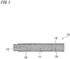
- Fig. 1 illustrates the non-combusted smoking article stored in a package of each embodiment.
- a non-combusted smoking article 10 has an aerosol generating section 11 that is heated to generate aerosol containing a smoking flavor component.
- the aerosol generating section 11 is a cylindrical body formed of a thermally stable material such as aluminum and stainless steel, and is filled with sheet tobacco or dried tobacco leaves.
- a carbon heat source 12 is provided on the tip end of the aerosol generating section 11.
- a filter 14 is connected to the rear end of the aerosol generating section 11.
- the entire outer periphery of the aerosol generating section 11 and the filter 14 and a part of the outer periphery of the carbon heat source 12 are wrapped and integrated by an enveloping material 15.
- the enveloping material 15 may be a paper tube created from paper whose main raw material is pulp, for example. Normal tobacco tissues, thick paper, or the like may be used for the paper tube.
- the basic weight of the thick paper may be around 100 to 300 g/m 2 .
- a filter used for a normal tobacco may be applied as the filter 14.
- the carbon heat source 12 is formed by pressing or extruding a mixture containing, for example, high-purity carbon particles, a non-combustible additive, an organic or inorganic binder, and water, and is formed into a columnar shape in the embodiment.
- a smoking end is formed on an end part of the filter 14 opposite to the aerosol generating section 11.
- the form of the non-combusted smoking article 10 may be modified in various ways, as a matter of course. For example, a through hole for taking in outside air may penetrate the carbon heat source 12 in the longitudinal direction thereof.
- the non-combusted smoking article 10 stored in the package of each embodiment has the carbon heat source 12 attached to its tip end, as mentioned above.
- the carbon heat source 12 is formed by binding carbon particles by a binder as mentioned earlier, and therefore is relatively brittle. For this reason, if the non-combusted smoking article 10 moves freely inside the package main body, vibration, impact from collision of the carbon heat source 12 with an inner wall face of the package or collision between the non-combusted smoking articles 10, and the like may break the carbon heat source 12 of the non-combusted smoking article 10, or cause the carbon heat source 12 to drop from the aerosol generating section 11. In such cases, it may be no longer possible to smoke the non-combusted smoking article 10.
- the package of each embodiment has a structure in which a package main body is partitioned. Details will be described below.
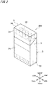
- Fig. 2 is a perspective view of a closed state of a package of a first embodiment.
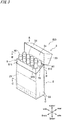
- Fig. 3 is a perspective view of an open state of the package of the first embodiment.
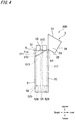
- Fig. 4 is a side view of the open state of the package of the first embodiment.
- Fig. 5 is a top view (view on arrow A of Fig. 3 ) of the open state of the package of the first embodiment.
- Fig. 6 is a cross-sectional view taken along B-B of Fig. 3 .
- Fig. 7 is a cross-sectional view taken along C-C of Fig. 3 .
- Fig. 8 is an exploded perspective view of the package of the first embodiment.
- a package 200 of a rod-like tobacco article that stores rod-like tobacco articles (hereinafter simply referred to as "package") of the first embodiment is a so-called hinge-lid package, and includes a package main body 2, and a lid 3 which is a lid part rotatably connected to the package main body 2 through a first hinge H1.
- the front side of a package 100 is defined as “front,” and the rear side is defined as “rear.”
- the lid 3 side of the package 100 is defined as “upper side,” and the opposite side (bottom side of package) is defined as “lower side.”
- the side wall side of the package 100 is defined as “side” or “horizontal direction.”
- the package main body 2 corresponds to a storage unit of the present invention, and is a storage box that stores therein non-combusted smoking articles 10.
- the upper end of the package main body 2 is an open end, and allows the non-combusted smoking article 10 to be taken out.
- the package main body 2 is a box formed into a rectangular parallelepiped shape whose upper end side is diagonally cut out.
- the package main body 2 has a package main body-front wall 21, a package main body-rear wall 22, package main body-side walls 23, 23, and a package main body-lower wall 24.
- Each of the package main body-front wall 21 and the package main body-rear wall 22 is a rectangle.
- the package main body-front wall 21 is a rectangle having a shorter height than the package main body-rear wall 22, and faces the package main body-rear wall 22.
- the paired package main body-side walls 23, 23 are connected to both side edges of the package main body-front wall 21 and the package main body-rear wall 22, and are each formed into a trapezoidal shape which is a rectangle whose upper end is an oblique side. In other words, each of the upper edges of the package main body-side walls 23, 23 is inclined in such a manner as to connect the upper end of the package main body-front wall 21 and the upper end of the package main body-rear wall 22.
- the package main body-lower wall 24 is a rectangle, and is connected to lower ends of the package main body-front wall 21 and the package main body-rear wall 22.
- the first hinge H1 is formed in the package main body-rear wall 22.
- the first hinge H1 is formed at the border between the package main body-rear wall 22 and a rear wall 32 of the lid, extends between rear parts thereof, and connects the package main body-rear wall 22 and the lid 3 such that they are rotatable relative to each other.
- the lid 3 covers the opening of the package main body 2.
- the lid 3 has a rectangular lid rear wall 32 connected to the first hinge H1, a rectangular lid upper wall 34 connected perpendicularly to the lid rear wall 32, a pair of trapezoidal lid side walls 33, 33 connected perpendicularly to the lid upper wall 34, and a lid front wall 31 facing the lid rear wall 32.
- Each of the lid side walls 33, 33 is connected to side edges of the lid rear wall 32 and the lid upper wall 34.
- the lid 3 when the lid 3 is closed, the oblique sides of the lid side walls 33, 33, that is, the oblique lower edges of the lid 3, coincide with the oblique sides of the package main body-side walls 22, 22, that is, the oblique upper edges of the package main body-side walls 23, 23. Additionally, the lower edge of the lid front wall 31 coincides with the upper edge of the package main body-front wall 21. As a result, the lid 3 covers the opening of the package main body 2, and a closed space is formed inside the package main body 2.
- the package 200 of the first embodiment is partitioned into multiple small regions SR by a first vertical partition unit 410 and a second vertical partition unit 420 that partition the package main body 2.
- the package main body 2 is partitioned into ten small regions SR, and each small region SR is capable of storing one non-combusted smoking article 10.
- the opening section of the small region SR is square.
- two horizontal partition units (first horizontal partition unit 51, second horizontal partition unit 52) partition the small region SR in the height direction (up-down direction).
- the first vertical partition unit 410 is provided between the first horizontal partition unit 51 and the second horizontal partition unit 52, and includes a first center wall 411 that partitions the package main body 2 into front and rear parts, and multiple first dividing walls 412 that extend from front to rear to partition the package main body 2 into multiple parts in the horizontal direction.
- the second vertical partition unit 420 is provided between the second horizontal partition unit 52 and the package main body-lower wall 24, and includes a second center wall 421 that partitions the package main body 2 into front and rear parts, and multiple second dividing walls 422 that extend from front to rear to partition the package main body 2 into multiple parts in the horizontal direction.
- the first center wall 411, the first dividing wall 412, the second center wall 421, and the second dividing wall 422 are an example of a vertical wall of the present invention.
- the inner face of the small region SR having a square opening section is not in contact with the circumferential face of the non-combusted smoking article 10.
- the opening section may be reduced, so that the inner face of the small region SR comes into contact with the circumferential face of the non-combusted smoking article 10 at four contact points.
- the inner face of the small region SR and the circumferential face of the non-combusted smoking article 10 may be brought into contact at four contact points, by reducing the opening section of the small region SR having a square opening section and configured of the first center wall 411 and the first dividing walls 412 constituting the first vertical partition unit 410, and the opening section of the small region SR having a square opening section and configured of the second center wall 421 and the second dividing walls 422 constituting the second vertical partition unit 420.
- This can more securely fix the position of the non-combusted smoking article 10.
- collision between the non-combusted smoking articles 10 and collision of the non-combusted smoking article 10 with an inner wall face of the package main body 2 can be more surely suppressed.
- the first center wall 411 is provided between and in parallel with the package main body-front wall 21 and the package main body-rear wall 22.
- the upper end of the first center wall 411 is slightly lower than the package main body-rear wall 22, and is in contact with a lower face of the first horizontal partition unit 51.
- the lower end of the first center wall 411 is higher than the package main body-lower wall 24, and is in contact with an upper face of the second horizontal partition unit 52.
- the first dividing wall 412 extends from the package main body-front wall 21 to the package main body-rear wall 22.
- the upper end and lower end of the first dividing wall are at the same height as the upper end and lower end of the first center wall 411.
- the second center wall 421 has a smaller height than the first center wall 411, but is provided between and in parallel with the package main body-front wall 21 and the package main body-rear wall 22, as in the case of the first center wall.
- the upper end of the second center wall 421 is in contact with a lower face of the second horizontal partition unit 52.
- the lower end of the second center wall 421 is in contact with an upper face of the package main body-lower wall 24.
- the second dividing wall 422 has a smaller height than the first dividing wall 412, but extends from the package main body-front wall 21 to the package main body-rear wall 22.
- the upper end and lower end of the second dividing wall are respectively at the same height as the upper end and lower end of the second center wall 421.
- a heat-resistant layer made of aluminum is formed on the surface of the second center wall 421 and the second dividing wall 422, to suppress deterioration by heat of the carbon heat source 12 of the smoked non-combusted smoking article 10.
- a horizontal partition unit 5 including the first horizontal partition unit 51 and the second horizontal partition unit 52 partitions the package main body 2 in the height direction (up-down direction), too.
- the horizontal partition unit 5 includes the first horizontal partition unit 51, the second horizontal partition unit 52, a horizontal partition unit-front wall 511, a horizontal partition unit-rear wall 512 extending along the inside of the package main body-rear wall 22, and horizontal partition unit-side walls 513, 513 extending along the inside of the package main body-side walls 23, 23.
- the first horizontal partition unit 51 is provided slightly lower than the upper end of the package main body-rear wall 22, so that a mouthpiece side-end part of the not yet smoked non-combusted smoking article 10 is exposed from an upper face of the first horizontal partition unit 51. Meanwhile, the first horizontal partition unit 51 is provided slightly lower than the upper end of the package main body-rear wall 22, so that a mouthpiece side-end face of the smoked non-combusted smoking article 10 is at the same level as the upper face of the first horizontal partition unit 51.
- the horizontal partition unit-side walls 513, 513 extending to the package main body-lower wall 24 are connected to both edges in the horizontal direction of the first horizontal partition unit 51, and support the first horizontal partition unit 51.
- the upper edge of the downwardly extending horizontal partition unit-rear wall 512 is connected to the rear edge of the first horizontal partition unit 51, and the upper edge of the downwardly extending horizontal partition unit-front wall 511 is connected to the front edge of the first horizontal partition unit 51.
- first horizontal partition unit-holes 515 corresponding to the ten small regions SR and through which the non-combusted smoking articles 10 penetrate are formed in the first horizontal partition unit 51.
- First horizontal partition unit-holding parts 516 that hold the non-combusted smoking article 10 are provided on the edge of the first horizontal partition unit-hole 515.
- the first horizontal partition unit-hole 515 is an octagon, and the triangular first horizontal partition unit-holding part 516 whose tip end points inward and downward is connected to each side of the octagon.
- the second horizontal partition unit 52 is provided slightly higher than the package main body-lower wall 24, so that the carbon heat source 12 of the smoked non-combusted smoking article 10 is stored between the package main body-lower wall 24 and the second horizontal partition unit 52.
- the second vertical partition unit 420 supports the second horizontal partition unit 52.
- the lower edge of the upwardly extending horizontal partition unit-rear wall 512 is connected to the rear edge of the second horizontal partition unit 52. That is, the first horizontal partition unit 51 and the second horizontal partition unit 52 are connected by the horizontal partition unit-rear wall 512.
- the horizontal partition unit-front wall 511 is split near the center in the height direction.
- second horizontal partition unit-holes 525 corresponding to the ten small regions SR and through which the non-combusted smoking articles 10 penetrate are formed in the second horizontal partition unit 52.
- Second horizontal partition unit-holding parts 526 that hold the non-combusted smoking article 10 are provided on the edge of the second horizontal partition unit-hole 525.
- the second horizontal partition unit-hole 525 is an octagon, and the triangular second horizontal partition unit-holding part 526 whose tip end points inward and downward is connected to each side of the octagon.
- the second horizontal partition unit 52 has a heat-resistant layer made of aluminum formed on a lower face of the second horizontal partition unit 52 and a lower face of the second horizontal partition unit-holding part 526, to suppress deterioration by heat of the carbon heat source 12 of the smoked non-combusted smoking article 10.
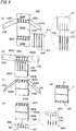
- Fig. 9 is a diagram describing an assembly procedure of the vertical partition unit and the horizontal partition unit of the package of the first embodiment.
- Fig. 10 illustrates a blank constituting a part of the vertical partition unit of the package of the first embodiment.
- Fig. 11 illustrates a blank constituting a part of the vertical partition unit of the package of the first embodiment.
- Fig. 12 illustrates a blank constituting a part of the vertical partition unit of the package of the first embodiment.
- Fig. 13 illustrates a blank constituting a part of the vertical partition unit of the package of the first embodiment.
- Fig. 14 illustrates a blank constituting the horizontal partition unit of the package of the first embodiment. Note that various existing blanks may be used for the package main body 2 and the lid 3.
- a heat-resistant layer made of aluminum is formed in regions corresponding to an inner side face of a lower part of the package main body-lower wall 24, an inner side face of a lower part of the package main body-front wall 21, an inner side face of a lower part of the package main body-rear wall 22, and an inner side face of a lower part of a package main body-side wall 0.
- a blank B21 illustrated in Fig. 10 is combined with a blank B22 illustrated in Fig. 11 and constitutes the first vertical partition unit 410.
- the blank B21 is a rectangle, and constitutes the first center wall 411.
- Four uniformly spaced linear cutouts C21 extending from the lower edge to the vicinity of the center in the height direction (up-down direction) are formed in the blank B21.
- the spacing between the cutouts C21 corresponds to one side of a square of the small region SR having a square opening section.
- the blank B22 illustrated in Fig. 11 is a rectangle, and constitutes the first dividing wall 412.
- a linear cutout C22 extending from the upper edge to the vicinity of the center in the up-down direction, is formed near the center in the horizontal direction of the blank B22.
- the width of the blank B22 is a length corresponding to two sides of a square of the small region SR having a square opening section.
- a blank B23 illustrated in Fig. 12 is combined with a blank B24 illustrated in Fig. 13 and constitutes the second vertical partition unit 420.
- the blank B23 is a rectangle, and constitutes the second center wall 421.
- Four uniformly spaced linear cutouts C23 extending from the lower edge to the vicinity of the center in the up-down direction are formed in the blank B23.
- the spacing between the cutouts C23 corresponds to one side of a square of the square small region SR.
- a heat-resistant layer made of aluminum is formed on both sides of the blank B23.
- the blank B24 illustrated in Fig. 13 is a rectangle, and constitutes the second dividing wall 422.
- a linear cutout C24 extending from the upper edge to the vicinity of the center in the up-down direction, is formed near the center in the horizontal direction of the blank B24.
- the width of the blank B24 is a length corresponding to two sides of a square of the small region SR having a square opening section.
- a heat-resistant layer made of aluminum is formed on both sides of the blank B24.
- a blank B25 illustrated in Fig. 14 constitutes the horizontal partition unit 5.
- the blank B25 has a rectangular first horizontal partition region R251 that constitutes the first horizontal partition unit 51.
- a radial cutout C25 that radially divides the first horizontal partition unit-hole 515 into eight is formed in the first horizontal partition region R251, in each of positions corresponding to the ten first horizontal partition unit-holes 515.
- a horizontal partition unit-front wall region R252 that constitutes the horizontal partition unit-front wall 511 (upper side) is connected to the upper edge of the first horizontal partition region R251.
- Rectangular horizontal partition unit-side wall regions R253, R253 that constitute the horizontal partition unit-side walls 513, 513 are connected to both side edges of the first horizontal partition region R251.
- a linear cutout C26 extending from the edge toward the first horizontal partition region R251 is formed in an end part of each of the horizontal partition unit-side wall regions R253, R253, on the opposite side of the first horizontal partition region R251.
- An end part of a second horizontal partition unit-center wall 45 engages with the linear cutout C26.
- the length (depth) of the linear cutout C26 is designed according to the height of the second horizontal partition unit-center wall 45. Additionally, of the rear side (rear side in Fig. 14 ) of the horizontal partition unit-side wall regions R253, R253, regions where the cutout C26 is formed are covered with a heat-resistant layer made of aluminum.
- a rectangular first horizontal partition-rear wall region R254 that constitutes the horizontal partition unit-rear wall 512 is connected to the lower edge of the first horizontal partition region R251.
- a rectangular second horizontal partition region R255 that constitutes the second horizontal partition unit 52 is connected to the lower edge of the first horizontal partition-rear wall region R254.
- the second horizontal partition region R255 includes a radial cutout C25 that radially divides the second horizontal partition unit-hole 525 into eight, in each of positions corresponding to the ten second horizontal partition unit-holes 525.
- a horizontal partition unit-front wall region R256 that constitutes the horizontal partition unit-front wall 511 (lower side) is connected to the second horizontal partition region R255.
- the blank B21 and the four blanks B22 are assembled such that the cutouts C21 in the blank B21 engage with the cutouts 22 in the blanks B22, and the blank B21 is perpendicular to the blanks B22.
- the first vertical partition unit 410 is formed.
- the blank B25 is folded at folding lines indicated by broken lines in Fig. 14 in such a manner as to enclose the first vertical partition unit 410.
- the first vertical partition unit 410 is arranged along the horizontal partition unit-rear wall region R254, and the blank B25 is folded such that the first horizontal partition region R251 extends along the upper end side of the first vertical partition unit 410, the horizontal partition unit-side wall regions R253, R253 extend along both sides in the horizontal direction of the first vertical partition unit 410, the horizontal partition unit-front wall region R252 extends along the upper part on the front side of the first vertical partition unit 410, the second horizontal partition region R255 extends along the lower end side of the first vertical partition unit 410, and the horizontal partition unit-front wall region R256 extends along the lower part on the front side of the first vertical partition unit 410.
- the blank B23 and the four blanks B24 are assembled such that the cutouts C23 in the blank B23 engage with the cutouts 24 in the blanks B24, and the blank B23 is perpendicular to the blanks B24.
- the second vertical partition unit 420 is formed. Both end parts in the horizontal direction of the second vertical partition unit 420 engage with the cutouts C26 formed in the horizontal partition unit-side wall regions R253, R253.
- the horizontal partition unit 5, the first vertical partition unit 410, and the second vertical partition unit 420 are integrated ( Fig. 9(e) ). Note that the assembly procedure described above is an example, and the invention is not limited to this.
- the integrated horizontal partition unit 5, first vertical partition unit 410, and second vertical partition unit 420 are stored in the package main body 2, and the package 200 of the first embodiment is completed.
- the package main body 2 is partitioned by the first vertical partition unit 410, the second vertical partition unit 420, the first horizontal partition unit 51, and the second horizontal partition unit 52, movement of the non-combusted smoking article 10 inside the package main body 2 is restricted.
- the first horizontal partition unit-holding parts 516 and the second horizontal partition unit-holding parts 526 restrict movement of the non-combusted smoking article 10.
- collision between the non-combusted smoking articles 10 and collision of the non-combusted smoking article 10 with an inner wall face of the package 100 are suppressed.
- damage of the non-combusted smoking article 10 can be reduced.
- breakage of the carbon heat source 12 of the non-combusted smoking article 10 and dropping of the carbon heat source 12 from the aerosol generating section 11 can be avoided.
- the first vertical partition unit 410, the second vertical partition unit 420, the first horizontal partition unit 51, and the second horizontal partition unit 52 partition the small regions SR completely.
- the smoked non-combusted smoking article 10 does not smear the not yet smoked non-combusted smoking article 10.
- carbon powder of the carbon heat source 12 of a not yet smoked or smoked non-combusted smoking article 10 and the ash of the carbon heat source 12 of a smoked non-combusted smoking article 10 can be kept from flying higher than the second horizontal partition unit 52.
- carbon powder of the carbon heat source 12 of a not yet smoked or smoked non-combusted smoking article 10 and the ash of the carbon heat source 12 of a smoked non-combusted smoking article 10 can be kept from flying to the outside of the package 100.
- the first vertical partition unit 410 can guide the tip end (carbon heat source 12) of the smoked non-combusted smoking article 10, which is inserted through the first horizontal partition unit-hole 515, to the second horizontal partition unit-hole 525. Also, since the first horizontal partition unit-holding parts 516 and the second horizontal partition unit-holding parts 526 point inward and downward, the smoked non-combusted smoking article 10 can be easily returned to the package main body 2. Moreover, the first horizontal partition unit-hole 515 and the circumferential face of the non-combusted smoking article 10 are in line (edge of hole) contact instead of surface contact. Hence, the resistance caused when the non-combusted smoking article 10 is taken in and out of the package 100 can be made smaller than when the parts are in surface contact.
- a heat-resistant layer made of aluminum is formed on the package main body-lower wall 24, the lower part of the package main body-front wall 21, the lower part of the package main body-rear wall 22, and the inner side face of the lower part of each of the package main body-side walls 23, 23 and also on the lower surface of the second horizontal partition unit 52 and the lower surface of the second horizontal partition unit-holding parts 526.
- the first horizontal partition unit 51 is designed to be slightly lower than the upper end of the package main body-rear wall 22, so that a mouthpiece side-end part of a not yet smoked non-combusted smoking article 10 is exposed from an upper face of the first horizontal partition unit 51, and a mouthpiece side-end face of the smoked non-combusted smoking article 10 is at the same level as the upper face of the first horizontal partition unit 51.
- Fig. 15 is a perspective view of an open state of the package of the first embodiment, in which not yet smoked non-combusted smoking articles are stored.
- Fig. 16 is a perspective view of an open state of the package of the first embodiment, in which two smoked non-combusted smoking articles are stored. As illustrated in Figs.
- the mouthpiece side-end parts of the not yet smoked non-combusted smoking articles 10 are exposed, it is easier to hold the not yet smoked non-combusted smoking article 10 stored in the package main body 2, and easily take the not yet smoked non-combusted smoking article 10 out of the package main body 2. Also, a not yet smoked non-combusted smoking article 10 and a smoked non-combusted smoking article 10 can be easily differentiated from each other. Additionally, since the smoking end side-end face of the smoked non-combusted smoking article 10 is aligned with the upper face of the first horizontal partition unit 51, excellent appearance can be achieved.
- the first horizontal partition unit 51 may be provided such that the smoking end side-end face of the smoked non-combusted smoking article 10 is lower than the upper face of the first horizontal partition unit 51. In this case, flying of carbon powder of the carbon heat source 12 of the not yet smoked or smoked non-combusted smoking article 10 and the ash of the carbon heat source 12 of the smoked non-combusted smoking article 10 becomes a concern.
- the first horizontal partition unit-hole 515 is configured of a circle having a smaller sectional area than the sectional area of the square opening section, and the inlet is formed narrow.
- first horizontal partition unit-holding parts 516 are provided in the first horizontal partition unit-hole 515
- second horizontal partition unit-holding parts 526 are provided in the second horizontal partition unit-hole 525, so that both holes are narrower than when there is no holding part.
- Fig. 17 is a perspective view of a closed state of a package of a second embodiment.
- Fig. 18 is a perspective view of an open state of the package of the second embodiment.
- Fig. 19 is a side view of the open state of the package of the second embodiment.
- Fig. 20 is a top view (view on arrow A of Fig. 18 ) of the open state of the package of the second embodiment.
- Fig. 21 is a cross-sectional view taken along B-B of Fig. 18 .
- Fig. 22 is a diagram describing contact points between small regions and non-combusted smoking articles in a package of a third embodiment.
- Fig. 23 is an exploded perspective view of the package of the second embodiment.
- a package 300 of the second embodiment includes a package main body 2 and a lid 3, where the package main body 2 and the lid are configured in the same manner as the first embodiment. Accordingly, descriptions of the package main body 2 and the lid 3 are omitted.
- the package main body 2 is partitioned into multiple small regions SR by a third vertical partition unit 6 that partitions the package main body 2.
- the package main body 2 is partitioned into 14 small regions SR, and each small region SR is capable of storing one non-combusted smoking article 10.
- the opening section of the small region SR is a diamond shape having diagonal lines of different lengths.
- the opening section of the small region SR is a diamond shape whose diagonal line in the front-rear direction is longer than its diagonal line in the horizontal direction.
- the third vertical partition unit 6 includes third diagonal walls 61 and fourth diagonal walls 62 that extend diagonally from front to rear to partition the package main body 2 in the horizontal direction.
- the third diagonal wall 61 and the fourth diagonal wall 62 are an example of the vertical wall of the present invention.
- the third diagonal wall 61 extends diagonally from a package main body-front wall 21 to a package main body-rear wall 22.
- the fourth diagonal wall 62 extends diagonally from the package main body-front wall 21 to the package main body-rear wall 22 in such a manner as to intersect with the third diagonal wall 61. Note that as an exception, the third diagonal wall 61 and the fourth diagonal wall 62 positioned on both sides in the horizontal direction extend diagonally from the package main body-side walls 23, 23, toward the package main body-front wall 21 or the package main body-rear wall 22.
- the upper ends of the third diagonal wall 61 and the fourth diagonal wall 62 are in contact with a lower face of a third horizontal partition unit 7, while the lower ends of the third diagonal wall 61 and the fourth diagonal wall 62 are in contact with a package main body-lower wall 24.
- a third horizontal partition unit 7 partitions the package main body 2 in the height direction, too.
- the third horizontal partition unit 7 includes a third horizontal partition unit-upper wall 70, a third horizontal partition unit-front wall 71 extending along the inside of the package main body-front wall 21, a third horizontal partition unit-rear wall 72 extending along the inside of the package main body-rear wall 22, and third horizontal partition unit-side walls 73, 73 extending along the inside of the package main body-side walls 23, 23.
- the third horizontal partition unit-upper wall 70 is provided slightly lower than the upper end of the package main body-rear wall 22, so that a mouthpiece side-end part of the not yet smoked non-combusted smoking article 10 is exposed from the third horizontal partition unit-upper wall 70. Meanwhile, the third horizontal partition unit-upper wall 70 is provided slightly lower than the upper end of the package main body-rear wall 22, so that a mouthpiece side-end face of the smoked non-combusted smoking article 10 is at the same level as the third horizontal partition unit-upper wall 70. Additionally, third horizontal partition unit-holes 701 corresponding to the 14 small regions SR and through which the non-combusted smoking articles 10 penetrate are formed in the third horizontal partition unit-upper wall 70.
- the upper edge of the downwardly extending third horizontal partition unit-front wall 71 is connected to the front edge of the third horizontal partition unit-upper wall 70.
- the upper edge of the downwardly extending third horizontal partition unit-rear wall 72 is connected to the rear edge of the third horizontal partition unit-upper wall 70.
- the upper edges of the downwardly extending third horizontal partition unit-side walls 73, 73 are connected to both side edges of the third horizontal partition unit-upper wall 70.
- Fig. 24 is a diagram describing an assembly procedure of the third vertical partition unit of the package of the second embodiment.
- Fig. 25 illustrates a blank constituting a part of the third vertical partition unit of the package of the second embodiment.
- Fig. 26 illustrates a blank constituting a part of the third vertical partition unit of the package of the second embodiment.
- Fig. 27 illustrates a blank constituting a part of the third vertical partition unit of the package of the second embodiment.
- Fig. 28 illustrates a blank constituting a part of the third vertical partition unit of the package of the second embodiment.
- Fig. 29 illustrates a blank constituting a part of the third vertical partition unit of the package of the second embodiment.
- various existing blanks may be used for the package main body 2 and the lid 3. Accordingly, descriptions of blanks constituting the package main body 2 and the lid 3 are omitted.
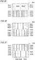
- Blanks B31, B32, B33, B34 are all rectangles having the same areas as a whole. Regions constituting the blanks B31, B32, B33, B34 differ among the blanks, and positions of cutouts and folding lines also differ among the blanks.
- the minimum width of a region corresponds to one side of a diamond shape of the small region SR having a diamond-shaped opening section.
- the folding lines include a mountain fold where the part is folded in such a manner as to bulge frontward and is indicated by a dash-dot line, and a valley fold where the part is folded in such a manner as to bulge rearward and is indicated by a dotted line.
- regions R311, R312, R313, R314, R315, R316 are connected in this order from the left in Fig. 25 .
- the regions R311, R312, R315, R316 each has a width corresponding to one side of a diamond shape of the small region SR having a diamond-shaped opening section, whereas the regions R313, R314 each has a width corresponding to three sides of the diamond shape.
- the border between the region R311 and the region R312 is a valley folding line, and a linear cutout C311 extending from the lower edge to the center is formed.
- the border between the region R312 and the region R313 is a valley folding line.
- Uniformly spaced linear cutouts C312, C313, C314 extending from the lower edge to the center are formed in the region R313.
- the border between the region R313 and the region R314 is a mountain folding line.
- Uniformly spaced linear cutouts C315, C316, C317 extending from the lower edge to the center are formed in the region R314.
- the border between the region R314 and the region R315 is a valley folding line.
- the border between the region R315 and the region R316 is a valley folding line, and a linear cutout C318 extending from the lower edge to the center is formed.
- regions R321, R322, R323, R324, R325, R326 are connected in this order from the left in Fig. 26 .
- the regions R321, R322, R325, R326 each has a width corresponding to one side of a diamond shape of the small region SR having a diamond-shaped opening section, whereas the regions R323, R324 each has a width corresponding to three sides of the diamond shape.
- the border between the region R321 and the region R322 is a mountain folding line, and a linear cutout C321 extending from the lower edge to the center is formed.
- the border between the region R322 and the region R323 is a mountain folding line.
- a cutout C322 extending from the lower edge to the center, a linear cutout C323 extending from the upper edge to the center, and a linear cutout C324 extending from the lower edge to the center are formed in a uniformly spaced manner in the region R323, in this order from the left in Fig. 26 .
- the border between the region R323 and the region R324 is a valley folding line.
- a linear cutout C325 extending from the lower edge to the center, a linear cutout C326 extending from the upper edge to the center, and a linear cutout C327 extending from the lower edge to the center are formed in a uniformly spaced manner in the region R324, in this order from the left in Fig. 26 .
- the border between the region R324 and the region R325 is a mountain folding line.
- the border between the region R325 and the region R326 is a mountain folding line, and a linear cutout C328 extending from the lower edge to the center is formed.
- regions R331, R332, R333, R334, R335 are connected in this order from the left in Fig. 27 .
- the regions R331, R335 each has a width corresponding to one side of a diamond shape of the small region SR having a diamond-shaped opening section
- the regions R332, R334 each has a width corresponding to three sides of the diamond shape
- the region R333 has a width corresponding to four sides of the diamond shape.
- the border between the region R331 and the region R322 is a mountain folding line, and a linear cutout C331 extending from the upper edge to the center is formed.
- a linear cutout C332 extending from the lower edge to the center, and a linear cutout C333 extending from the upper edge to the center are formed in a uniformly spaced manner in the region R332, in this order from the left in Fig. 27 .
- the border between the region R332 and the region R333 is a valley folding line.
- a linear cutout C334 extending from the upper edge to the center, a linear cutout C335 extending from the lower edge to the center, and a linear cutout C336 extending from the upper edge to the center are formed in a uniformly spaced manner in the region R333, in this order from the left in Fig. 27 .
- the border between the region R333 and the region R334 is a mountain folding line.
- a linear cutout C337 extending from the upper edge to the center, and a linear cutout C338 extending from the lower edge to the center are formed in a uniformly spaced manner in the region R334, in this order from the left in Fig. 27 .
- the border between the region R334 and the region R335 is a valley folding line, and a linear cutout C339 extending from the upper edge to the center is formed.
- regions R341, R342, R343, R344, R345 are connected in this order from the left in Fig. 28 .
- the regions R341, R345 each has a width corresponding to one side of a diamond shape of the small region SR having a diamond-shaped opening section
- the regions R342, R344 each has a width corresponding to three sides of the diamond shape
- the region R343 has a width corresponding to four sides of the diamond shape.
- the border between the region R341 and the region R342 is a valley folding line, and a linear cutout C341 extending from the upper edge to the center is formed.
- Uniformly spaced linear cutouts C342, C343 extending from the upper edge to the center are formed in the region R342, in this order from the left in Fig. 28 .
- the border between the region R342 and the region R343 is a mountain folding line.
- Uniformly spaced linear cutouts C344, C345, C346 extending from the upper edge to the center are formed in the region R343, in this order from the left in Fig. 28 .
- the border between the region R343 and the region R344 is a valley folding line.
- Uniformly spaced linear cutouts C347, C348 extending from the upper edge to the center are formed in the region R344, in this order from the left in Fig. 28 .
- the border between the region R344 and the region R345 is a mountain folding line, and a linear cutout C349 extending from the upper edge to the center is formed.
- a blank B35 illustrated in Fig. 29 constitutes the third horizontal partition unit 7.
- the blank B35 has a rectangular third horizontal partition unit-upper wall region R351 that constitutes the third horizontal partition unit-upper wall 70.
- a circular cutout C35 is formed in each of positions corresponding to the 14 third horizontal partition unit-holes 701 in the third horizontal partition unit-upper wall region R351.
- a rectangular third horizontal partition unit-front region R352 that constitutes the third horizontal partition unit-front wall 71 is connected to the lower edge of the third horizontal partition unit-upper wall region R351.
- a rectangular third horizontal partition unit-rear wall region R353 that constitutes the third horizontal partition unit-rear wall 72 is connected to the upper edge of the third horizontal partition unit-upper wall region R351.
- Rectangular third horizontal partition unit-side wall regions R353, R353 that constitute the third horizontal partition unit-side walls 73, 73 are connected to both side edges of the third horizontal partition unit-upper wall region R351.
- the mountain folding line is folded into a mountain and the valley folding line is folded into a valley to appropriately engage the cutouts with one another.
- the cutout C341 in the blank B34 engages with the cutout C321 in the blank B32.
- the cutout C342 in the blank B34 engages with the cutout C332 in the blank B33.
- the cutout C343 in the blank B34 engages with the cutout C312 in the blank B31.
- the cutout C344 in the blank B34 engages with the cutout C324 in the blank B32.
- the cutout C344 in the blank B34 engages with the cutout C335 in the blank B33.
- the cutout C345 in the blank B34 engages with the cutout C324 in the blank B32.
- the cutout C346 in the blank B34 engages with the cutout C315 in the blank B31.
- the cutout C347 in the blank B34 engages with the cutout C338 in the blank B33.
- the cutout C348 in the blank B34 engages with the cutout C327 in the blank B32.
- the cutout C349 in the blank B34 engages with the cutout C318 in the blank B31.
- the cutout C331 in the blank B33 engages with the cutout C311 in the blank B31.
- the cutout C332 in the blank B33 engages with the cutout C342 in the blank B34.
- the cutout C333 in the blank B33 engages with the cutout C322 in the blank B32.
- the cutout C334 in the blank B33 engages with the cutout C314 in the blank B31.
- the cutout C335 in the blank B33 engages with the cutout C344 in the blank B34.
- the cutout C336 in the blank B33 engages with the cutout C325 in the blank B32.
- the cutout C337 in the blank B33 engages with the cutout C317 in the blank B31.
- the cutout C338 in the blank B33 engages with the cutout C347 in the blank B34.
- the cutout C339 in the blank B33 engages with the cutout C328 in the blank B32.
- the cutout C321 in the blank B32 engages with the cutout C341 in the blank B34.
- the cutout C322 in the blank B32 engages with the cutout C333 in the blank B33.
- the cutout C323 in the blank B32 engages with the cutout C313 in the blank B31.
- the cutout C324 in the blank B32 engages with the cutout C344 in the blank B34.
- the cutout C325 in the blank B32 engages with the cutout C336 in the blank B33.
- the cutout C326 in the blank B32 engages with the cutout C316 in the blank B31.
- the cutout C327 in the blank B32 engages with the cutout C348 in the blank B34.
- the cutout C328 in the blank B32 engages with the cutout C339 in the blank B33.
- the cutout C311 in the blank B31 engages with the cutout C331 in the blank B33.
- the cutout C312 in the blank B31 engages with the cutout C343 in the blank B34.
- the cutout C313 in the blank B31 engages with the cutout C323 in the blank B32.
- the cutout C314 in the blank B31 engages with the cutout C334 in the blank B33.
- the cutout C315 in the blank B31 engages with the cutout C346 in the blank B34.
- the cutout C316 in the blank B31 engages with the cutout C326 in the blank B32.
- the cutout C317 in the blank B31 engages with the cutout C337 in the blank B33.
- the cutout C318 in the blank B31 engages with the cutout C349 in the blank B34.
- the third vertical partition unit 6 is formed.
- the third horizontal partition unit 7 is formed by folding the blank B35 at the folding lines. As illustrated in Fig. 23 , the third vertical partition unit 6 is stored in the package main body 2, and the third horizontal partition unit 7 is covered on the upper face of the third vertical partition unit 6 to complete the package 300 of the second embodiment.
- the package main body 2 is partitioned by the third vertical partition unit 6 and the third horizontal partition unit 7, movement of the non-combusted smoking article 10 inside the package main body 2 is restricted.
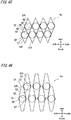
- the package main body 2 is partitioned into small regions SR each having a diamond-shaped opening section, where the inner face of the small region SR having a diamond-shaped opening section is in contact with the circumferential face of the non-combusted smoking article 10 at four contact points TP.
- the inner face of the small region SR having a diamond-shaped opening section is in contact with the circumferential face of the non-combusted smoking article 10 at the four contact points TP, so that gaps are formed between the inner face of the small region SR and the circumferential face of the non-combusted smoking article 10.
- the resistance caused when the non-combusted smoking article 10 is taken in and out of the package 100 can be made smaller than when the opening section is circular (line contact instead of point contact), a pentagon (five contact points), or a more complex polygon (five or more contact points). Also, more gaps can be formed between the inner face of the small region SR and the circumferential face of the non-combusted smoking article 10. As a result, the non-combusted smoking article 10 can be taken out easily from the package 100, and the smoked non-combusted smoking article 10 as a tobacco butt can be easily returned to the package main body 2 of the package 300.
- the cutouts are appropriately engaged with one another in each of the four blanks B31, B32, B33, B34 by folding the mountain folding line into a mountain, and the valley folding line into a valley.
- the small region SR configured of the third diagonal wall 61 and the fourth diagonal wall 62 is allowed to deform. This makes it easy to take out the non-combusted smoking article 10, and to return the smoked non-combusted smoking article 10 as a tobacco butt to the small region SR of the package.
- the small region SR is formed into a diamond shape having diagonal lines of different lengths.
- Fig. 22 omits the package main body 2, and illustrates the vertical partition unit 4, namely, the small regions SR, the non-combusted smoking articles 10, and the contact points TP between the small regions SR and the non-combusted smoking articles 10.
- the small region SR in the package 300 of the second embodiment is a diamond shape having diagonal lines of different lengths, the contact points TP between the stored non-combusted smoking articles 10 and the walls of the small regions SR are not supplied between adjacent small regions SR in the configuration.
- the third diagonal wall 61 or the fourth diagonal wall 62 deflects more easily than when the contact points TP are shared. Hence, it is easier to take out the non-combusted smoking article 10, and to return the smoked non-combusted smoking article 10 as a tobacco butt to the small region SR of the package.
- the third vertical partition unit 6 and the third horizontal partition unit 7 partition the small regions SR completely. Hence, even when a smoked non-combusted smoking article 10 is returned to the package main body 2, the smoked non-combusted smoking article 10 does not smear the not yet smoked non-combusted smoking article 10. Additionally, according to the third horizontal partition unit 7, carbon powder of the carbon heat source 12 of a not yet smoked or smoked non-combusted smoking article 10 and the ash of the carbon heat source 12 of a smoked non-combusted smoking article 10 can be kept from flying to the outside of the package 300.
- the third horizontal partition unit-upper wall 70 is designed to be slightly lower than the upper end of the package main body-rear wall 22, so that an end part of a not yet smoked non-combusted smoking article 10 is exposed from the third horizontal partition unit-upper wall 70, and a smoking end side-end face of the smoked non-combusted smoking article 10 is at the same level as the third horizontal partition unit-upper wall 70.
- Fig. 30 is a perspective view of an open state of the package of the second embodiment, in which not yet smoked non-combusted smoking articles are stored.
- Fig. 31 is a perspective view of an open state of the package of the second embodiment, in which two smoked non-combusted smoking articles are stored. As illustrated in Figs.
- the mouthpiece side-end parts of the not yet smoked non-combusted smoking articles 10 are exposed, it is easier to hold the not yet smoked non-combusted smoking article 10 stored in the package main body 2, and easily take the not yet smoked non-combusted smoking article 10 out of the package main body 2. Also, a not yet smoked non-combusted smoking article 10 and a smoked non-combusted smoking article 10 can be easily differentiated from each other. Additionally, since the smoking end side-end face of the smoked non-combusted smoking article 10 is aligned with the third horizontal partition unit-upper wall 70, excellent appearance can be achieved.
- the third horizontal partition unit-upper wall 70 may be provided such that the smoking end side-end face of the smoked non-combusted smoking article 10 is lower than the third horizontal partition unit-upper wall 70.
- flying of carbon powder of the carbon heat source 12 of the not yet smoked or smoked non-combusted smoking article 10 and the ash of the carbon heat source 12 of the smoked non-combusted smoking article 10 becomes a concern.
- the third horizontal partition unit-hole 701 is configured of a circle having a smaller sectional area than the sectional area of the diamond-shaped opening section, and the inlet is formed narrow. Hence, it is possible to suppress flying of carbon powder of the carbon heat source 12 of the not yet smoked or smoked non-combusted smoking article 10 and the ash of the carbon heat source 12 of the smoked non-combusted smoking article 10.
- Fig. 32 is a perspective view of an open state of a package of a third embodiment.
- Fig. 33 is a side view of an open state of the package of the third embodiment.
- a package 400 of the third embodiment includes a package main body 2 and a lid 3. The package main body 2 and the lid 3 are configured in the same manner as the first embodiment.
- the opening section of the package main body 2 is partitioned into diamond-shaped small regions SR by a fourth vertical partition unit 8. Note, however, that the package 400 of the third embodiment is formed such that the sectional area of the small region SR gradually decreases from upper to lower parts. In other words, the walls that form the small region SR are inclined.
- the package 400 of the third embodiment since the package main body 2 is partitioned by the fourth vertical partition unit 8, movement of a non-combusted smoking article 10 inside the package main body 2 is restricted.
- the opening section of the package main body 2 is partitioned into diamond-shaped small regions SR by the fourth vertical partition unit 8, and an inner face of the small region SR having a diamond-shaped opening section is in contact with the circumferential face of the non-combusted smoking article 10 at four contact points, in a lower part of the small region SR.
- collision between the non-combusted smoking articles 10 and collision of the non-combusted smoking article 10 with an inner wall face of the package 400 are suppressed.
- damage of the non-combusted smoking article 10 can be reduced.
- breakage of the carbon heat source 12 of the non-combusted smoking article 10 and dropping of the carbon heat source 12 from an aerosol generating section 11 can be avoided.
- the inner face of the small region SR having a diamond-shaped opening section is in contact with the circumferential face of the non-combusted smoking article 10 at four contact points, so that gaps are formed between the inner face of the small region SR and the circumferential face of the non-combusted smoking article 10.
- the resistance caused when the non-combusted smoking article 10 is taken in and out of the package 100 can be made smaller than when the opening section is circular (line contact instead of point contact), a pentagon (five contact points), or a more complex polygon (five or more contact points).
- more gaps can be formed between the inner face of the small region SR and the circumferential face of the non-combusted smoking article 10.
- the non-combusted smoking article 10 can be taken out easily from the package 100, and the smoked non-combusted smoking article 10 as a tobacco butt can be easily returned to the package main body 2.
- the package 400 of the third embodiment is formed such that the sectional area of the small region SR gradually decreases from upper to lower parts. Accordingly, the non-combusted smoking article 10 can be fixed by the lower part of the small region SR, and a smoked non-combusted smoking article 10 can be more easily returned to the package main body 2.
- Fig. 34 is a perspective view of a closed state of a package of a fourth embodiment.
- Fig. 35 is a perspective view of an open state of the package of the fourth embodiment.
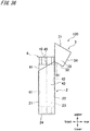
- Fig. 36 is a side view of the open state of the package of the fourth embodiment.
- Fig. 37 is a top view (view on arrow A of Fig. 35 ) of the open state of the package of the fourth embodiment.
- the package 100 of the fourth embodiment is a so-called hinge-lid package, and includes a package main body 2, and a lid 3 which is a lid part rotatably connected to the package main body 2 through a first hinge H1.
- the package main body 2 and the lid are configured in the same manner as the first embodiment. Accordingly, descriptions of the package main body 2 and the lid 3 are omitted.
- the package main body 2 is partitioned into multiple small regions SR by a vertical partition unit 4 that partitions the inner part thereof.
- the package main body 2 is partitioned into 14 small regions SR, and each small region SR is capable of storing one non-combusted smoking article 10.
- the vertical partition unit 4 includes a center wall 45 that partitions the package main body 2 into front and rear parts, first diagonal walls 46 and second diagonal walls 47 that extend diagonally from front to rear to partition the package main body 2 into multiple parts in the horizontal direction, a vertical partition unit-front wall 41 that extends along the inside of a package main body-front wall 21, a vertical partition unit-rear wall 42 that extends along the inside of a package main body-rear wall 22, and vertical partition unit-side walls 43, 43 that extend along the inside of package main body-side walls 23, 23.
- the center wall 45, the first diagonal walls 46, the second diagonal walls 47, the vertical partition unit-front wall 41, the vertical partition unit-rear wall 42, and the vertical partition unit-side walls 43, 43 are an example of the vertical wall of the present invention.
- the small region SR stores each non-combusted smoking article 10 separately by a region having a triangular open section that extends in the depth direction (height direction) of the package main body 2, and that is partitioned by the center wall 45, the first diagonal walls 46, the second diagonal walls 47, the vertical partition unit-front wall 41, and the vertical partition unit-rear wall 42.
- the center wall 45 is provided between and in parallel with the package main body-front wall 21 and the package main body-rear wall 22.
- the center wall 45 is arranged such that its upper end is near the center of the upper edge of the package main body-side walls 23, 23, and its lower end is in contact with an inner face of a package main body-lower wall 24.
- the first diagonal wall 46 extends diagonally from the package main body-front wall 21 to the package main body-rear wall 22.
- the second diagonal wall 47 extends diagonally from the package main body-front wall 21 to the package main body-rear wall 22, in such a manner as to intersect with the first diagonal wall 46 at the position of the center wall 45.
- the first diagonal wall 46 and the second diagonal wall 47 positioned on both sides in the horizontal direction extend diagonally from the package main body-side walls 23, 23, toward the package main body-front wall 21 or the package main body-rear wall 22.
- the upper ends of the first diagonal wall 46 and the second diagonal wall 47 are at the same height as the upper end of the center wall 45.
- the lower ends of the first diagonal wall 46 and the second diagonal wall 47 are not in contact with the package main body-lower wall 24, and are higher than the lower end of the center wall 45.
- the vertical partition unit-front wall 41, the vertical partition unit-rear wall 42, and the vertical partition unit-side walls 43, 43 are arranged along the inside of the package main body-front wall 21, the package main body-rear wall 22, and the package main body-side walls 23, 23.
- the upper ends of the vertical partition unit-front wall 41, the vertical partition unit-rear wall 42, and the vertical partition unit-side walls 43, 43 are provided at the same height as the upper end of the center wall 45.
- the upper ends of the vertical partition unit-front wall 41 and the vertical partition unit-side walls 43, 43 protrude higher upward than the upper end of the package main body-front wall 21, and abuts on the inside of the lid front wall 31 and the lid side walls 33, 33 when the lid 3 is closed.
- these protruding regions also function as a so-called inner frame, and can facilitate closing of the lid 3.
- the lower ends of the vertical partition unit-front wall 41 and the vertical partition unit-side walls 43, 43 are not in contact with the package main body-lower wall 24, and are higher than the lower end of the center wall 45.
- first diagonal wall 46, the second diagonal wall 47, the vertical partition unit-front wall 41, the vertical partition unit-rear wall 42, and the vertical partition unit-side walls 43, 43 may come into contact with the package main body-lower wall 24. This can enhance independence of each small region SR. Accordingly, even when a smoked non-combusted smoking article 10 is returned to the small region SR, the ash does not move to other small regions SR. Hence, a smoked non-combusted smoking article 10 can be kept from smearing a not yet smoked non-combusted smoking article 10.
- Fig. 39 is a diagram describing an assembly procedure of the vertical partition unit of the package of the fourth embodiment.
- Fig. 40 illustrates a blank constituting a part of the vertical partition unit of the package of the fourth embodiment.
- Fig. 41 illustrates a blank constituting a part of the vertical partition unit of the package of the fourth embodiment. Note that various existing blanks may be used for the package main body 2 and the lid 3. Accordingly, descriptions of blanks constituting the package main body 2 and the lid 3 are omitted.
- a blank B1 illustrated in Fig. 40 constitutes the center wall 45.
- the blank B1 is a rectangle, and has three uniformly spaced linear cutouts C1 extending from the upper edge to the vicinity of the lower edge.
- the spacing between the cutouts C1 corresponds to one side of a triangle of the small region SR having a triangular opening section.
- a blank B2 illustrated in Fig. 41 constitutes the first diagonal walls 46, the second diagonal walls 47, the vertical partition unit-front wall 41, the vertical partition unit-rear wall 42, and the vertical partition unit-side walls 43, 43, by combining two blanks B2 in inverted orientations.
- the blank B2 is rectangular as a whole, and has a front wall region R1 that constitutes the vertical partition unit-front wall 41.
- a side wall region R2 that constitutes a part of the vertical partition unit-side wall 43 is connected to the side edge of the front wall region R1.
- a first diagonal wall region R3 that constitutes the first diagonal wall 46 on one side in the horizontal direction is connected to the side edge of the side wall region R2.
- a linear cutout C2 extending from the upper end to the center is formed at the border between the side wall region R2 and the first diagonal wall region R3.
- a second diagonal wall region R4 that constitutes a part of multiple second diagonal walls is connected to the side edge of the first diagonal wall region R3.
- a linear cutout C2 extending from the upper end to the center is formed in the center in the horizontal direction of the second diagonal wall region R4.
- a first diagonal wall region R5 that constitutes a part of the multiple first diagonal walls is connected to the side edge of the second diagonal wall region R4.
- a linear cutout C2 extending from the upper end to the center is formed in the center in the horizontal direction of the first diagonal wall region R5.
- a second diagonal wall region R6 that constitutes a part of the multiple second diagonal walls is connected to the side edge of the first diagonal wall region R5.
- a linear cutout C2 extending from the upper end to the center is formed in the center in the horizontal direction of the second diagonal wall region R6.
- a first diagonal wall region R7 that constitutes the first diagonal wall on the other side in the horizontal direction is connected to the side edge of the second diagonal wall region R6.
- a side wall region R8 that constitutes a part of the vertical partition unit-side wall 43 is connected to the side edge of the first diagonal wall region R7.
- a linear cutout C2 extending from the upper end to the center is formed at the border between the first diagonal wall region R7 and the side wall region R8.
- a rear wall region R9 that constitutes the vertical partition unit-rear wall 42 is connected to the side edge of the side wall region R8.
- the side wall region R2, the first diagonal wall region R3, the first diagonal wall region R7, and the side wall region R8 each has a width corresponding to one side of a triangle of the small region SR having a triangular opening section.
- the side wall region R4, the side wall region R5, and the side wall region R6 each has a width corresponding to two sides of the triangle.
- the two blanks B2 are each folded into wave shapes at folding lines indicated by broken lines in Fig. 41 .
- the two blanks B2 are combined such that the multiple cutouts C2 in the blanks B2 engage with one another.
- the blank B1 and the blanks B2 are combined such that the cutouts C1 in the blank B1, the cutout C2 in the second diagonal wall region R4, the cutout C2 in the first diagonal wall region R5, and the cutout C2 in the second diagonal wall region R6 engage with one another.
- Fig. 39(a) the two blanks B2 are each folded into wave shapes at folding lines indicated by broken lines in Fig. 41 .
- the two blanks B2 are combined such that the multiple cutouts C2 in the blanks B2 engage with one another.
- the blank B1 and the blanks B2 are combined such that the cutouts C1 in the blank B1, the cutout C2 in the second diagonal wall region R4, the cutout C2 in the first diagonal wall region R5, and the cutout C2 in the
- the broken lines are folded such that the front wall region R1 of one blank B2 is superimposed on the front wall region R1 of the other blank B2, the side wall region R2 of one blank B2 is flush with the side wall region R8 of the other blank B2, and the rear wall region R9 of one blank B2 is superimposed on the rear wall region R9 of the other blank.
- the vertical partition unit 4 is formed as illustrated in Fig. 39(e) . Note that the above assembly procedure of the vertical partition unit 4 is an example, and the invention is not limited to this.
- the formed vertical partition unit 4 is stored in the package main body 2, and the package 100 of the fourth embodiment is completed.
- the package main body 2 is partitioned by the vertical partition unit 4, movement of the non-combusted smoking article 10 inside the package main body 2 is restricted. Specifically, as illustrated in Fig. 37 , the package main body 2 is partitioned into small regions SR each having a triangular opening section, where the inner face of the small region SR having a triangular opening section is in contact with the circumferential face of the non-combusted smoking article 10 at three contact points TP. Hence, collision between the non-combusted smoking articles 10 and collision of the non-combusted smoking article 10 with an inner wall face of the package main body 2 can be suppressed. As a result, damage of the non-combusted smoking article 10 can be reduced.
- the inner face of the small region SR having a triangular opening section is in contact with the circumferential face of the non-combusted smoking article 10 at the three contact points TP, so that gaps are formed between the inner face of the small region SR and the circumferential face of the non-combusted smoking article 10.
- the resistance caused when the non-combusted smoking article 10 is taken in and out of the package 100 can be made smaller than when the opening section is circular (line contact instead of point contact), a pentagon (five contact points), or a more complex polygon (five or more contact points). Also, more gaps can be formed between the inner face of the small region SR and the circumferential face of the non-combusted smoking article 10. As a result, the non-combusted smoking article 10 can be taken out easily from the package 100, and the smoked non-combusted smoking article 10 as a tobacco butt can be easily returned to the package main body 2 of the package 100.
- Fig. 42 is a diagram describing contact points between small regions and non-combusted smoking articles in a package of a modification of the fourth embodiment.
- Fig. 42 omits the package main body 2, and illustrates a vertical partition unit 4, namely, small regions SR, non-combusted smoking articles 10, and contact points TP between the small regions SR and the non-combusted smoking articles 10.
- the small region SR stores each non-combusted smoking article 10 separately by a region having a triangular opening section that extends in the depth direction (height direction) of the package main body, and that is partitioned by a center wall 45, first diagonal walls 46, second diagonal walls 47, a vertical partition unit-front wall 41, and a vertical partition unit-rear wall 42.
- the opening section of the small region SR is a regular triangle in the vertical partition unit 4 of the package 100 of the fourth embodiment
- the opening section of the small region SR is an isosceles triangle in the vertical partition unit 4 of the package of the modification of the fourth embodiment.
- the contact points TP except for those on the center wall 45 are not shared between adjacent small regions SR.
- the first diagonal wall 46 or the second diagonal wall 47 deflects more easily than when the contact points TP are shared. Hence, it is easier to take out the non-combusted smoking article 10, and to return the smoked non-combusted smoking article 10 as a tobacco butt to the small region SR of the package.
- the vertical partition unit 4 of the package of the modification of the fourth embodiment may be formed of two blanks. Note that the vertical partition unit 4 of the package of the fourth embodiment and the vertical partition unit 4 of the package of the modification of the fourth embodiment may be formed integrally by resin.
- Figs. 43 to 46 are diagrams describing contact points between small regions and non-combusted smoking articles of modifications. Figs. 43 to 46 omit the package main body 2, and illustrate vertical partition units 4a, 4b, 4c, 4d, namely, small regions SR, non-combusted smoking articles 10, and contact points TP between the small regions SR and the non-combusted smoking articles 10.
- Fig. 43 is a diagram describing contact points between a small region having an oval opening section and a non-combusted smoking article.
- the opening section of the small region SR is oval, and there are two contact points TP between an inner face of the small region SR and the circumferential face of the non-combusted smoking article 10. Gaps are formed between the inner face of the small region SR and the circumferential face of the non-combusted smoking article 10.
- the vertical walls forming the small region SR extend in the depth direction (height direction) of the package main body.
- the small region SR is configured such that the two contact points TP are not shared between adjacent small regions SR.
- the vertical partition unit 4a illustrated in Fig. 43 is configured not to share contact points TP between adjacent small regions SR, by alternately arranging, in the horizontal direction, a single small region SR and two small regions SR arranged next to each other in the front-rear direction.
- Fig. 44 is a diagram describing contact points between a small region having an isosceles triangle-shaped opening section and a non-combusted smoking article.
- the opening section of the small region SR is an isosceles triangle, and there are three contact points TP between an inner face of the small region SR and the circumferential face of the non-combusted smoking article 10. Gaps are formed between the inner face of the small region SR and the circumferential face of the non-combusted smoking article 10.
- the vertical walls forming the small region SR extend in the depth direction (height direction) of the package main body.
- the small region SR is configured such that the three contact points TP are not shared between adjacent small regions SR.
- the vertical partition unit 4b illustrated in Fig. 44 is configured not to share contact points TP between adjacent small regions SR, by, unlike the small regions SR of the modification of the fourth embodiment, alternately arranging, in the horizontal direction, differently oriented small regions SR, and not arranging the small regions SR along the front-rear direction.
- Fig. 45 is a diagram illustrating contact points between a small region having a diamond-shaped opening section and a non-combusted smoking article.
- the opening section of the small region SR is a diamond shape, and there are four contact points TP between an inner face of the small region SR and the circumferential face of the non-combusted smoking article 10. Gaps are formed between the inner face of the small region SR and the circumferential face of the non-combusted smoking article 10.
- the vertical walls forming the small region SR extend in the depth direction (height direction) of the package main body.
- the small region SR is configured such that the four contact points TP are not shared between adjacent small regions SR.
- the vertical partition unit 4c illustrated in Fig. 45 is formed thinner and longer in the front-rear direction than the small region SR of the third embodiment, which also has a diamond-shaped opening section.
- the vertical partition unit 4c is also configured not to share contact points TP between adjacent small regions SR.
- Fig. 46 is a diagram describing contact points between a small region having an elongated hexagonal opening section and a non-combusted smoking article.
- the opening section of the small region SR is an elongated hexagon, and there are four contact points TP between an inner face of the small region SR and the circumferential face of the non-combusted smoking article 10. Gaps are formed between the inner face of the small region SR and the circumferential face of the non-combusted smoking article 10.
- the vertical walls forming the small region SR extend in the depth direction (height direction) of the package main body.
- the small region SR is configured such that the four contact points TP are not shared between adjacent small regions SR.
- the vertical partition unit 4d illustrated in Fig. 46 is configured not to share contact points TP between adjacent small regions SR, by alternately shifting the small regions SR to front and rear sides in the horizontal direction.
- gaps are formed between the inner face of the small region SR and the circumferential face of the non-combusted smoking article 10.
- the non-combusted smoking article 10 can be taken out easily, and the smoked non-combusted smoking article 10 as a tobacco butt can be easily returned to the small region SR of the package. Since the contact points TP are not shared between the adjacent small regions SR, the walls forming the small regions SR can more easily deflect than when the contact points TP are shared between the adjacent small regions SR.
- the non-combusted smoking articles 10 can be taken out easily, and the smoked non-combusted smoking article 10 as a tobacco butt can be easily returned to the small region SR of the package.
- the above embodiments have been described by using the non-combusted smoking article 10 with the carbon heat source 12 attached to the tip end thereof as an example of a rod-like tobacco article stored in the package.
- tobaccos or other rod-like tobacco articles may be stored instead.
- a heat-resistant layer formed of aluminum may be formed on the inner side face or the like of the package main body 2, or a lower part of the small region SR in the package 200 of the first embodiment, the package 400 of the third embodiment, and the package 100 of the fourth embodiment as well.
- the heat-resistant layer is not limited to aluminum, and may be other materials such as heat-resistant plastic, asbestos, or other base material, as long as it has a heat-resistive property.
- the aforementioned package 200 of the first embodiment, package 300 of the second embodiment, package 400 of the third embodiment, and package 100 of the fourth embodiment may be configured of paper.
- the material is not particularly limited. All or part (e.g., vertical partition unit) of the package 200 of the first embodiment, the package 300 of the second embodiment, the package 400 of the third embodiment, and the package 100 of the fourth embodiment may be configured of resin.
- the vertical partition units 4a, 4b, 4c, 4d illustrated in Figs. 43 to 46 may be configured of paper, or may be configured of resin.
Landscapes
- Engineering & Computer Science (AREA)
- Mechanical Engineering (AREA)
- Packaging Of Annular Or Rod-Shaped Articles, Wearing Apparel, Cassettes, Or The Like (AREA)
- Cartons (AREA)
Abstract
Description
- The present invention relates to a package of a rod-like tobacco article.
- A package (wrapping) of a rod-like tobacco article that stores rod-like tobacco articles has been widely known. An example of the package is a hinge-lid package. A hinge-lid package is a box package including a lid part called a lid that is openably connected to an outer box. As an example of a hinge-lid package,
Patent document 1 describes a technique of partitioning a main body of a package.Patent documents Patent documents Patent document 6 discloses a fire extinguishing device for tobaccos. - In recent years, studies have been made to develop non-combusted rod-like tobacco articles that enable the user to taste a smoking flavor of a tobacco without combusting tobacco leaves. For example, a known non-combusted smoking article includes a heat source which is a heating member attached to the tip end, and a smoking flavor-generating material which is an adequate base material retaining a smoking flavor component. This non-combusted smoking article generates aerosol containing the smoking flavor component by heating, instead of combusting, the smoking flavor-generating material by heat from combusting the heat source. A carbon heat source formed into a cylindrical shape is often used as a heat source attached to the tip end of a non-combusted rod-like tobacco article of this type. For example, a carbon heat source is obtained by forming a mixture containing high-purity carbon particles, a non-combustible additive, an organic or inorganic binder, and water.
-
- [Patent document 1] Chinese Utility Model No.
201604917 - [Patent document 2] Japanese Patent Laid-Open No.
2001-86973 - [Patent document 3] Japanese Patent Laid-Open No.
2004-115123 - [Patent document 4] Japanese Patent Laid-Open No.
2007-259839 - [Patent document 5] Japanese Patent Laid-Open No.
6-70740 - [Patent document 6] Japanese Patent Laid-Open No.
9-322750 - When a smoked rod-like tobacco article is returned to a package of a rod-like tobacco article, the smoked rod-like tobacco article may smear a not yet smoked rod-like tobacco article. A smeared smoking end of a not yet smoked rod-like tobacco article may hinder smoking of the rod-like tobacco article.
- The present invention has been made in view of the above problem, and an objective thereof is to provide a package of a rod-like tobacco article in which a not yet smoked rod-like tobacco article is less likely to be smeared when a smoked rod-like tobacco article is returned to the package of a rod-like tobacco article.
- To solve the above problem, the present invention provides, in a storage unit that stores a rod-like tobacco article, a horizontal partition unit that partitions the storage unit in a horizontal direction perpendicular to a depth direction of the storage unit to suppress flying of the ash of a smoked tobacco article.
- Specifically, the present invention includes: a storage unit that stores therein a rod-like tobacco article; and a horizontal partition unit that partitions the storage unit in a horizontal direction perpendicular to a depth direction of the storage unit to suppress flying of the ash of a smoked tobacco article, in which the horizontal partition unit includes a horizontal partition unit-hole that allows a single rod-like tobacco article to penetrate therethrough.
- According to the present invention, the ash of a smoked tobacco article can be kept from flying by means of the horizontal partition unit. As a result, a not yet smoked rod-like tobacco article is less likely to be smeared when a smoked rod-like tobacco article is returned to the package of a rod-like tobacco article.
- The package of a rod-like tobacco article of the present invention may further include a lid part that is rotatably connected to a part of an open end of the storage unit, and opens and closes the open end. The package of a rod-like tobacco article of the present invention can be favorably used for a so-called hinge-lid package. Note that the package of a rod-like tobacco article of the present invention is widely usable for a package including a storage unit, such as a so-called slide package.
- The horizontal partition unit may be provided in the vicinity of the open end. This can keep the ash of a smoked rod-like tobacco article from flying to the outside of the storage unit, when the smoked rod-like tobacco article is returned to the storage unit.
- The horizontal partition unit may be provided in an open end of the storage unit or in the vicinity of the open end, where an end part of a not yet smoked rod-like tobacco article stored in the storage unit is exposed. Since the end part of the not yet smoked rod-like tobacco article is exposed, it is easier to hold the rod-like tobacco article stored in the storage unit of the package, and the rod-like tobacco article can be easily taken out of the package. The horizontal partition unit can be used to clearly differentiate between an unused rod-like tobacco article and a used rod-like tobacco article. As a result, the user can be kept from erroneously taking out a smoked rod-like tobacco article. A rod-like tobacco article having a carbon heat source on the tip end thereof may be used, and in this case, the horizontal partition unit may be provided such that it becomes flush with an end face of a smoked and shortened rod-like tobacco article stored in the storage unit. A rod-like tobacco article having a carbon heat source becomes shorter after it has been smoked, and its length is almost constant. By providing the horizontal partition unit such that is flush with the end face of a smoked rod-like tobacco article, it is possible to clearly differentiate between an unused rod-like tobacco article and a used rod-like tobacco article. Appearance can also be improved.
- The horizontal partition unit may be provided in a lower part of the storage unit. This can keep the ash accumulated in a lower part of the storage unit from flying. Note that in this case, the horizontal partition unit should preferably be on the open end side of the storage unit instead of on the end part opposite to the mouthpiece side (smoking side) of the smoked rod-like tobacco article. Note that the horizontal partition unit provided in the lower part of the storage unit may be provided on its own, or may be provided together with a horizontal partition unit in an open end or in the vicinity of the open end.
- The horizontal partition unit may have a horizontal partition unit-holding part that is provided on the edge of the horizontal partition unit-hole to hold the rod-like tobacco article. This can restrict movement of the rod-like tobacco article. Hence, collision between the rod-like tobacco articles and collision of the rod-like tobacco article with an inner wall face of the package can be suppressed. As a result, damage of the rod-like tobacco article can be reduced.
- The package of a rod-like tobacco article of the present invention may further include a vertical partition unit that uses a vertical wall extending in a depth direction of the storage unit to partition the storage unit into small regions for storing the rod-like tobacco articles one by one. There may be two to four contact points between an inner wall of the small region and a contour of the rod-like tobacco article stored in the small region. According to the present invention, since the storage unit is partitioned by the vertical partition unit, movement of the rod-like tobacco article inside the storage unit can be restricted. Hence, collision between the rod-like tobacco articles and collision of the rod-like tobacco article with an inner wall face of the package can be suppressed. As a result, damage of the rod-like tobacco article can be reduced. According to the present invention, there are two to four contact points between the inner wall of the small region and the contour of the rod-like tobacco article stored in the small region, the inner wall of the small region is in point contact with the contour of the rod-like tobacco article stored in the small region, and gaps are formed in regions other than the contact points, between the inner wall of the small region and the contour of the rod-like tobacco article stored in the small region. As a result, the rod-like tobacco article can be taken out easily, and the smoked rod-like tobacco article as a tobacco butt can be easily returned to the storage unit of the package. A columnar rod-like tobacco article is preferably used.
- The package of a rod-like tobacco article of the present invention may be configured to have multiple small regions. Thus, multiple rod-like tobacco articles can be stored, and damage of the rod-like tobacco article can be suppressed.
- When there are multiple small regions in the package of a rod-like tobacco article of the present invention, the package may be configured such that the contact points are not shared between adjacent small regions. When the contact points are not shared, the vertical wall deflects outward more easily than when the contact points are shared. Hence, the rod-like tobacco article can be taken out easily, and the smoked rod-like tobacco article as a tobacco butt can be easily returned to the storage unit of the package.
- When there are multiple small regions in the package of a rod-like tobacco article of the present invention, the package may be configured such that the contact points are not shared among any of the small regions. When none of the contact points are shared, the vertical wall deflects easily in any direction. Hence, the rod-like tobacco article can be taken out more easily, than when some of the contact points are shared. The smoked rod-like tobacco article as a tobacco butt can be more easily returned to the storage unit of the package.
- The vertical wall of the vertical partition unit may extend from an open end of the storage unit or the vicinity of the open end to the bottom of the storage unit. With this, the small region can be made into an independent region. When a smoked rod-like tobacco article is returned to the storage unit, there is concern that the smoked rod-like tobacco article may smear the not yet smoked rod-like tobacco article. Since the small regions are independent in the package of a rod-like tobacco article of the present invention, the smoked rod-like tobacco article can be kept from smearing the not yet smoked rod-like tobacco article.
- The shape of the opening section of the small region may be at least one of an oval, a triangle, a square, a diamond, a pentagon, and a hexagon. If the rod-like tobacco article is columnar, an oval is an example where there are two contact points. A triangle is an example where there are three contact points. A square, a diamond, a pentagon, and a hexagon are an example where there are four contact points.
In the case of a pentagon or a hexagon, the contact points increases to five or six if a regular polygon is used. Hence, the length of sides and internal angles need to be adjusted to by elongating the shape, for example, to form four contact points. By setting the shape of the opening section of the small region in the above manner, an adequate gap is formed between the rod-like tobacco article and the vertical wall, as compared to setting the opening section of the small region to a circle or a more complex polygon than a pentagon. Consequently, the rod-like tobacco article can be taken out even more easily, and the smoked rod-like tobacco article as a tobacco butt can be more easily returned to the storage unit of the package. - In the package of a rod-like tobacco article of the present invention, any one of the storage unit and the vertical partition unit may have, in an area in the vicinity of a heat source of a rod-like tobacco article stored in the storage unit, a heat-resistant part that suppresses deterioration by heat of a heat source of a smoked rod-like tobacco article. This can suppress deterioration of the package by heat of a heat source of a smoked rod-like tobacco article.
- The rod-like tobacco article may include a carbon heat source provided on the tip end side thereof, an aerosol generation section connected to the rear end of the carbon heat source, and an enveloping material that wraps a part of the carbon heat source and the outer periphery of the aerosol generation section. In the case of a rod-like tobacco article having a carbon heat source on the tip end part thereof, smoking may be hindered if the carbon heat source on the tip end part breaks by impact, or falls from the smoking flavor generating material. As described above, the package of a rod-like tobacco article of the present invention can suppress damage of a rod-like tobacco article stored therein. Hence, the package of a rod-like tobacco article of the present invention can be favorably used as a package of a rod-like tobacco article that has a carbon heat source on the tip end side thereof. For example, the rod-like tobacco article may be a cigarette (filter cigarette, non-filter cigarette), a cigar, a cigarillo, an electronic tobacco, and the like.
- Note that the means for solving the problem of the present invention may be combined in any possible way.
- The present invention can provide a package of a rod-like tobacco article in which a smoked rod-like tobacco article can be kept from smearing a not yet smoked rod-like tobacco article, when the smoked rod-like tobacco article is returned to the package of a rod-like tobacco article.
-
- [
Fig. 1] Fig. 1 illustrates a non-combusted smoking article stored in a package of each embodiment. - [
Fig. 2] Fig. 2 is a perspective view of a closed state of a package of a first embodiment. - [
Fig. 3] Fig. 3 is a perspective view of an open state of the package of the first embodiment. - [
Fig. 4] Fig. 4 is a side view of the open state of the package of the first embodiment. - [
Fig. 5] Fig. 5 is a top view of the open state of the package of the first embodiment. - [
Fig. 6] Fig. 6 is a cross-sectional view taken along B-B ofFig. 3 . - [
Fig. 7] Fig. 7 is a cross-sectional view taken along C-C ofFig. 3 . - [
Fig. 8] Fig. 8 is an exploded perspective view of the package of the first embodiment. - [
Fig. 9] Fig. 9 is a diagram describing an assembly procedure of a vertical partition unit and a horizontal partition unit of the package of the first embodiment. - [
Fig. 10] Fig. 10 illustrates a blank constituting a part of the vertical partition unit of the package of the first embodiment. - [
Fig. 11] Fig. 11 illustrates a blank constituting a part of the vertical partition unit of the package of the first embodiment. - [
Fig. 12] Fig. 12 illustrates a blank constituting a part of the vertical partition unit of the package of the first embodiment. - [
Fig. 13] Fig. 13 illustrates a blank constituting a part of the vertical partition unit of the package of the first embodiment. - [
Fig. 14] Fig. 14 illustrates a blank constituting the horizontal partition unit of the package of the first embodiment. - [
Fig. 15] Fig. 15 is a perspective view of an open state of the package of the first embodiment, in which not yet smoked non-combusted smoking articles are stored. - [
Fig. 16] Fig. 16 is a perspective view of an open state of the package of the first embodiment, in which two smoked non-combusted smoking articles are stored. - [
Fig. 17] Fig. 17 is a perspective view of a closed state of a package of a second embodiment. - [
Fig. 18] Fig. 18 is a perspective view of an open state of the package of the second embodiment. - [
Fig. 19] Fig. 19 is a side view of the open state of the package of the second embodiment. - [
Fig. 20] Fig. 20 is a top view of the open state of the package of the second embodiment. - [
Fig. 21] Fig. 21 is a cross-sectional view taken along B-B ofFig. 18 . - [
Fig. 22] Fig. 22 is a diagram describing contact points between small regions and non-combusted smoking articles in a package of a third embodiment. - [
Fig. 23] Fig. 23 is an exploded perspective view of the package of the second embodiment. - [
Fig. 24] Fig. 24 is a diagram describing an assembly procedure of a third vertical partition unit of the package of the second embodiment. - [
Fig. 25] Fig. 25 illustrates a blank constituting a part of the third vertical partition unit of the package of the second embodiment. - [
Fig. 26] Fig. 26 illustrates a blank constituting a part of the third vertical partition unit of the package of the second embodiment. - [
Fig. 27] Fig. 27 illustrates a blank constituting a part of the third vertical partition unit of the package of the second embodiment. - [
Fig. 28] Fig. 28 illustrates a blank constituting a part of the third vertical partition unit of the package of the second embodiment. - [
Fig. 29] Fig. 29 illustrates a blank constituting a part of the third vertical partition unit of the package of the second embodiment. - [
Fig. 30] Fig. 30 is a perspective view of an open state of the package of the second embodiment, in which not yet smoked non-combusted smoking articles are stored. - [
Fig. 31] Fig. 31 is a perspective view of an open state of the package of the second embodiment, in which two smoked non-combusted smoking articles are stored. - [
Fig. 32] Fig. 32 is a perspective view of an open state of the package of the third embodiment. - [
Fig. 33] Fig. 33 is a side view of the open state of the package of the third embodiment. - [
Fig. 34] Fig. 34 is a perspective view of a closed state of a package of a fourth embodiment. - [
Fig. 35] Fig. 35 is a perspective view of an open state of the package of the fourth embodiment. - [
Fig. 36] Fig. 36 is a side view of the open state of the package of the fourth embodiment. - [
Fig. 37] Fig. 37 is a top view of the open state of the package of the fourth embodiment. - [
Fig. 38] Fig. 38 is an exploded perspective view of the package of the fourth embodiment. - [
Fig. 39] Fig. 39 is a diagram describing an assembly procedure of a vertical partition unit of the package of the fourth embodiment. - [
Fig. 40] Fig. 40 illustrates a blank constituting a part of the vertical partition unit of the package of the fourth embodiment. - [
Fig. 41] Fig. 41 illustrates a blank constituting a part of the vertical partition unit of the package of the fourth embodiment. - [
Fig. 42] Fig. 42 is a diagram describing contact points between small regions and non-combusted smoking articles in a package of a modification of the fourth embodiment. - [
Fig. 43] Fig. 43 is a diagram describing contact points between a small region having an oval opening section and a non-combusted smoking article. - [
Fig. 44] Fig. 44 is a diagram describing contact points between a small region having an isosceles triangle-shaped opening section and a non-combusted smoking article. - [
Fig. 45] Fig. 45 is a diagram illustrating contact points between a small region having a diamond-shaped opening section and a non-combusted smoking article. - [
Fig. 46] Fig. 46 is a diagram describing contact points between a small region having an elongated hexagonal opening section and a non-combusted smoking article. - Embodiments of a package of a rod-like tobacco article of the present invention will be described with reference to the drawings. Note that dimensions, material, shape, relative positions and the like of components described in the embodiments are not intended to limit the technical scope of the invention, if not specifically stated.
- First, as an example of a rod-like tobacco article, a non-combusted smoking article stored in a package of each embodiment will be described. The package of each of the following embodiments may be suitably used as a package of the non-combusted smoking article.
Fig. 1 illustrates the non-combusted smoking article stored in a package of each embodiment. Anon-combusted smoking article 10 has anaerosol generating section 11 that is heated to generate aerosol containing a smoking flavor component. Theaerosol generating section 11 is a cylindrical body formed of a thermally stable material such as aluminum and stainless steel, and is filled with sheet tobacco or dried tobacco leaves. - A
carbon heat source 12 is provided on the tip end of theaerosol generating section 11. Afilter 14 is connected to the rear end of theaerosol generating section 11. The entire outer periphery of theaerosol generating section 11 and thefilter 14 and a part of the outer periphery of thecarbon heat source 12 are wrapped and integrated by an envelopingmaterial 15. The envelopingmaterial 15 may be a paper tube created from paper whose main raw material is pulp, for example. Normal tobacco tissues, thick paper, or the like may be used for the paper tube. The basic weight of the thick paper may be around 100 to 300 g/m2. A filter used for a normal tobacco may be applied as thefilter 14. Thecarbon heat source 12 is formed by pressing or extruding a mixture containing, for example, high-purity carbon particles, a non-combustible additive, an organic or inorganic binder, and water, and is formed into a columnar shape in the embodiment. A smoking end is formed on an end part of thefilter 14 opposite to theaerosol generating section 11. The form of thenon-combusted smoking article 10 may be modified in various ways, as a matter of course. For example, a through hole for taking in outside air may penetrate thecarbon heat source 12 in the longitudinal direction thereof. - The
non-combusted smoking article 10 stored in the package of each embodiment has thecarbon heat source 12 attached to its tip end, as mentioned above. Thecarbon heat source 12 is formed by binding carbon particles by a binder as mentioned earlier, and therefore is relatively brittle. For this reason, if thenon-combusted smoking article 10 moves freely inside the package main body, vibration, impact from collision of thecarbon heat source 12 with an inner wall face of the package or collision between thenon-combusted smoking articles 10, and the like may break thecarbon heat source 12 of thenon-combusted smoking article 10, or cause thecarbon heat source 12 to drop from theaerosol generating section 11. In such cases, it may be no longer possible to smoke thenon-combusted smoking article 10. Additionally, collision of thecarbon heat source 12 with an inner wall face of the package or collision between thenon-combusted smoking articles 10 may cause scraping on thecarbon heat source 12 and generate carbon powder, whereby a surface of the envelopingmaterial 15 or the smoking end of thefilter 14 may be smeared. Hence, the package of each embodiment has a structure in which a package main body is partitioned. Details will be described below. -
Fig. 2 is a perspective view of a closed state of a package of a first embodiment.Fig. 3 is a perspective view of an open state of the package of the first embodiment.Fig. 4 is a side view of the open state of the package of the first embodiment.Fig. 5 is a top view (view on arrow A ofFig. 3 ) of the open state of the package of the first embodiment.Fig. 6 is a cross-sectional view taken along B-B ofFig. 3 .Fig. 7 is a cross-sectional view taken along C-C ofFig. 3 .Fig. 8 is an exploded perspective view of the package of the first embodiment. - A
package 200 of a rod-like tobacco article that stores rod-like tobacco articles (hereinafter simply referred to as "package") of the first embodiment is a so-called hinge-lid package, and includes a packagemain body 2, and alid 3 which is a lid part rotatably connected to the packagemain body 2 through a first hinge H1. Note that in the specification below, the front side of apackage 100 is defined as "front," and the rear side is defined as "rear." Thelid 3 side of thepackage 100 is defined as "upper side," and the opposite side (bottom side of package) is defined as "lower side." The side wall side of thepackage 100 is defined as "side" or "horizontal direction." - The package
main body 2 corresponds to a storage unit of the present invention, and is a storage box that stores thereinnon-combusted smoking articles 10. The upper end of the packagemain body 2 is an open end, and allows thenon-combusted smoking article 10 to be taken out. - The package
main body 2 is a box formed into a rectangular parallelepiped shape whose upper end side is diagonally cut out. The packagemain body 2 has a package main body-front wall 21, a package main body-rear wall 22, package main body-side walls lower wall 24. Each of the package main body-front wall 21 and the package main body-rear wall 22 is a rectangle. The package main body-front wall 21 is a rectangle having a shorter height than the package main body-rear wall 22, and faces the package main body-rear wall 22. The paired package main body-side walls front wall 21 and the package main body-rear wall 22, and are each formed into a trapezoidal shape which is a rectangle whose upper end is an oblique side. In other words, each of the upper edges of the package main body-side walls front wall 21 and the upper end of the package main body-rear wall 22. The package main body-lower wall 24 is a rectangle, and is connected to lower ends of the package main body-front wall 21 and the package main body-rear wall 22. The first hinge H1 is formed in the package main body-rear wall 22. The first hinge H1 is formed at the border between the package main body-rear wall 22 and arear wall 32 of the lid, extends between rear parts thereof, and connects the package main body-rear wall 22 and thelid 3 such that they are rotatable relative to each other. - The
lid 3 covers the opening of the packagemain body 2. Thelid 3 has a rectangular lidrear wall 32 connected to the first hinge H1, a rectangular lidupper wall 34 connected perpendicularly to the lidrear wall 32, a pair of trapezoidallid side walls upper wall 34, and alid front wall 31 facing the lidrear wall 32. Each of thelid side walls rear wall 32 and the lidupper wall 34. When thelid 3 is open, thenon-combusted smoking article 10 can be taken in and out from the opening of the packagemain body 2. Meanwhile, when thelid 3 is closed, the oblique sides of thelid side walls lid 3, coincide with the oblique sides of the package main body-side walls side walls lid front wall 31 coincides with the upper edge of the package main body-front wall 21. As a result, thelid 3 covers the opening of the packagemain body 2, and a closed space is formed inside the packagemain body 2. - The
package 200 of the first embodiment is partitioned into multiple small regions SR by a firstvertical partition unit 410 and a secondvertical partition unit 420 that partition the packagemain body 2. In the first embodiment, the packagemain body 2 is partitioned into ten small regions SR, and each small region SR is capable of storing onenon-combusted smoking article 10. The opening section of the small region SR is square. Later-mentioned two horizontal partition units (firsthorizontal partition unit 51, second horizontal partition unit 52) partition the small region SR in the height direction (up-down direction). The firstvertical partition unit 410 is provided between the firsthorizontal partition unit 51 and the secondhorizontal partition unit 52, and includes afirst center wall 411 that partitions the packagemain body 2 into front and rear parts, and multiple first dividingwalls 412 that extend from front to rear to partition the packagemain body 2 into multiple parts in the horizontal direction. The secondvertical partition unit 420 is provided between the secondhorizontal partition unit 52 and the package main body-lower wall 24, and includes asecond center wall 421 that partitions the packagemain body 2 into front and rear parts, and multiplesecond dividing walls 422 that extend from front to rear to partition the packagemain body 2 into multiple parts in the horizontal direction. Thefirst center wall 411, thefirst dividing wall 412, thesecond center wall 421, and thesecond dividing wall 422 are an example of a vertical wall of the present invention. - Note that in the
package 200 of the first embodiment, the inner face of the small region SR having a square opening section is not in contact with the circumferential face of thenon-combusted smoking article 10. However, the opening section may be reduced, so that the inner face of the small region SR comes into contact with the circumferential face of thenon-combusted smoking article 10 at four contact points. Specifically, the inner face of the small region SR and the circumferential face of thenon-combusted smoking article 10 may be brought into contact at four contact points, by reducing the opening section of the small region SR having a square opening section and configured of thefirst center wall 411 and the first dividingwalls 412 constituting the firstvertical partition unit 410, and the opening section of the small region SR having a square opening section and configured of thesecond center wall 421 and thesecond dividing walls 422 constituting the secondvertical partition unit 420. This can more securely fix the position of thenon-combusted smoking article 10. As a result, collision between thenon-combusted smoking articles 10 and collision of thenon-combusted smoking article 10 with an inner wall face of the packagemain body 2 can be more surely suppressed. - The
first center wall 411 is provided between and in parallel with the package main body-front wall 21 and the package main body-rear wall 22. The upper end of thefirst center wall 411 is slightly lower than the package main body-rear wall 22, and is in contact with a lower face of the firsthorizontal partition unit 51. The lower end of thefirst center wall 411 is higher than the package main body-lower wall 24, and is in contact with an upper face of the secondhorizontal partition unit 52. Thefirst dividing wall 412 extends from the package main body-front wall 21 to the package main body-rear wall 22. The upper end and lower end of the first dividing wall are at the same height as the upper end and lower end of thefirst center wall 411. - The
second center wall 421 has a smaller height than thefirst center wall 411, but is provided between and in parallel with the package main body-front wall 21 and the package main body-rear wall 22, as in the case of the first center wall. The upper end of thesecond center wall 421 is in contact with a lower face of the secondhorizontal partition unit 52. The lower end of thesecond center wall 421 is in contact with an upper face of the package main body-lower wall 24. Thesecond dividing wall 422 has a smaller height than thefirst dividing wall 412, but extends from the package main body-front wall 21 to the package main body-rear wall 22. The upper end and lower end of the second dividing wall are respectively at the same height as the upper end and lower end of thesecond center wall 421. A heat-resistant layer made of aluminum is formed on the surface of thesecond center wall 421 and thesecond dividing wall 422, to suppress deterioration by heat of thecarbon heat source 12 of the smokednon-combusted smoking article 10. - In the
package 200 of the first embodiment, in addition to the aforementioned firstvertical partition unit 410 and the secondvertical partition unit 420, ahorizontal partition unit 5 including the firsthorizontal partition unit 51 and the secondhorizontal partition unit 52 partitions the packagemain body 2 in the height direction (up-down direction), too. To be specific, thehorizontal partition unit 5 includes the firsthorizontal partition unit 51, the secondhorizontal partition unit 52, a horizontal partition unit-front wall 511, a horizontal partition unit-rear wall 512 extending along the inside of the package main body-rear wall 22, and horizontal partition unit-side walls side walls horizontal partition unit 51 is provided slightly lower than the upper end of the package main body-rear wall 22, so that a mouthpiece side-end part of the not yet smokednon-combusted smoking article 10 is exposed from an upper face of the firsthorizontal partition unit 51. Meanwhile, the firsthorizontal partition unit 51 is provided slightly lower than the upper end of the package main body-rear wall 22, so that a mouthpiece side-end face of the smokednon-combusted smoking article 10 is at the same level as the upper face of the firsthorizontal partition unit 51. The horizontal partition unit-side walls lower wall 24 are connected to both edges in the horizontal direction of the firsthorizontal partition unit 51, and support the firsthorizontal partition unit 51. The upper edge of the downwardly extending horizontal partition unit-rear wall 512 is connected to the rear edge of the firsthorizontal partition unit 51, and the upper edge of the downwardly extending horizontal partition unit-front wall 511 is connected to the front edge of the firsthorizontal partition unit 51. Additionally, first horizontal partition unit-holes 515 corresponding to the ten small regions SR and through which thenon-combusted smoking articles 10 penetrate are formed in the firsthorizontal partition unit 51. First horizontal partition unit-holdingparts 516 that hold thenon-combusted smoking article 10 are provided on the edge of the first horizontal partition unit-hole 515. The first horizontal partition unit-hole 515 is an octagon, and the triangular first horizontal partition unit-holdingpart 516 whose tip end points inward and downward is connected to each side of the octagon. - The second
horizontal partition unit 52 is provided slightly higher than the package main body-lower wall 24, so that thecarbon heat source 12 of the smokednon-combusted smoking article 10 is stored between the package main body-lower wall 24 and the secondhorizontal partition unit 52.
The secondvertical partition unit 420 supports the secondhorizontal partition unit 52. The lower edge of the upwardly extending horizontal partition unit-rear wall 512 is connected to the rear edge of the secondhorizontal partition unit 52. That is, the firsthorizontal partition unit 51 and the secondhorizontal partition unit 52 are connected by the horizontal partition unit-rear wall 512. In the first embodiment, the horizontal partition unit-front wall 511 is split near the center in the height direction. As in the case of the firsthorizontal partition unit 51, second horizontal partition unit-holes 525 corresponding to the ten small regions SR and through which thenon-combusted smoking articles 10 penetrate are formed in the secondhorizontal partition unit 52. Second horizontal partition unit-holdingparts 526 that hold thenon-combusted smoking article 10 are provided on the edge of the second horizontal partition unit-hole 525. The second horizontal partition unit-hole 525 is an octagon, and the triangular second horizontal partition unit-holdingpart 526 whose tip end points inward and downward is connected to each side of the octagon. Note that unlike the firsthorizontal partition unit 51, the secondhorizontal partition unit 52 has a heat-resistant layer made of aluminum formed on a lower face of the secondhorizontal partition unit 52 and a lower face of the second horizontal partition unit-holdingpart 526, to suppress deterioration by heat of thecarbon heat source 12 of the smokednon-combusted smoking article 10. -
Fig. 9 is a diagram describing an assembly procedure of the vertical partition unit and the horizontal partition unit of the package of the first embodiment.Fig. 10 illustrates a blank constituting a part of the vertical partition unit of the package of the first embodiment.Fig. 11 illustrates a blank constituting a part of the vertical partition unit of the package of the first embodiment.Fig. 12 illustrates a blank constituting a part of the vertical partition unit of the package of the first embodiment.Fig. 13 illustrates a blank constituting a part of the vertical partition unit of the package of the first embodiment.Fig. 14 illustrates a blank constituting the horizontal partition unit of the package of the first embodiment. Note that various existing blanks may be used for the packagemain body 2 and thelid 3. Accordingly, descriptions of blanks constituting the packagemain body 2 and thelid 3 are omitted. A heat-resistant layer made of aluminum is formed in regions corresponding to an inner side face of a lower part of the package main body-lower wall 24, an inner side face of a lower part of the package main body-front wall 21, an inner side face of a lower part of the package main body-rear wall 22, and an inner side face of a lower part of a package main body-side wall 0. - A blank B21 illustrated in
Fig. 10 is combined with a blank B22 illustrated inFig. 11 and constitutes the firstvertical partition unit 410. The blank B21 is a rectangle, and constitutes thefirst center wall 411. Four uniformly spaced linear cutouts C21 extending from the lower edge to the vicinity of the center in the height direction (up-down direction) are formed in the blank B21. The spacing between the cutouts C21 corresponds to one side of a square of the small region SR having a square opening section. - The blank B22 illustrated in
Fig. 11 is a rectangle, and constitutes thefirst dividing wall 412. A linear cutout C22 extending from the upper edge to the vicinity of the center in the up-down direction, is formed near the center in the horizontal direction of the blank B22. The width of the blank B22 is a length corresponding to two sides of a square of the small region SR having a square opening section. - A blank B23 illustrated in
Fig. 12 is combined with a blank B24 illustrated inFig. 13 and constitutes the secondvertical partition unit 420. The blank B23 is a rectangle, and constitutes thesecond center wall 421. Four uniformly spaced linear cutouts C23 extending from the lower edge to the vicinity of the center in the up-down direction are formed in the blank B23. The spacing between the cutouts C23 corresponds to one side of a square of the square small region SR. A heat-resistant layer made of aluminum is formed on both sides of the blank B23. - The blank B24 illustrated in
Fig. 13 is a rectangle, and constitutes thesecond dividing wall 422. A linear cutout C24 extending from the upper edge to the vicinity of the center in the up-down direction, is formed near the center in the horizontal direction of the blank B24. The width of the blank B24 is a length corresponding to two sides of a square of the small region SR having a square opening section. A heat-resistant layer made of aluminum is formed on both sides of the blank B24. - When assembled, a blank B25 illustrated in
Fig. 14 constitutes thehorizontal partition unit 5. The blank B25 has a rectangular first horizontal partition region R251 that constitutes the firsthorizontal partition unit 51. In order to form the first horizontal partition unit-hole 515 and the first horizontal partition unit-holdingpart 516, a radial cutout C25 that radially divides the first horizontal partition unit-hole 515 into eight is formed in the first horizontal partition region R251, in each of positions corresponding to the ten first horizontal partition unit-holes 515. - A horizontal partition unit-front wall region R252 that constitutes the horizontal partition unit-front wall 511 (upper side) is connected to the upper edge of the first horizontal partition region R251. Rectangular horizontal partition unit-side wall regions R253, R253 that constitute the horizontal partition unit-
side walls center wall 45 engages with the linear cutout C26. For this reason, the length (depth) of the linear cutout C26 is designed according to the height of the second horizontal partition unit-center wall 45. Additionally, of the rear side (rear side inFig. 14 ) of the horizontal partition unit-side wall regions R253, R253, regions where the cutout C26 is formed are covered with a heat-resistant layer made of aluminum. - A rectangular first horizontal partition-rear wall region R254 that constitutes the horizontal partition unit-
rear wall 512 is connected to the lower edge of the first horizontal partition region R251. A rectangular second horizontal partition region R255 that constitutes the secondhorizontal partition unit 52 is connected to the lower edge of the first horizontal partition-rear wall region R254. As in the case of the first horizontal partition region R251, in order to form the second horizontal partition unit-hole 525 and the second horizontal partition unit-holdingpart 526, the second horizontal partition region R255 includes a radial cutout C25 that radially divides the second horizontal partition unit-hole 525 into eight, in each of positions corresponding to the ten second horizontal partition unit-holes 525. A horizontal partition unit-front wall region R256 that constitutes the horizontal partition unit-front wall 511 (lower side) is connected to the second horizontal partition region R255. - As illustrated in
Fig. 9(a) , the blank B21 and the four blanks B22 are assembled such that the cutouts C21 in the blank B21 engage with thecutouts 22 in the blanks B22, and the blank B21 is perpendicular to the blanks B22. As a result, the firstvertical partition unit 410 is formed. Next, as illustrated inFigs. 9(b), (c) , the blank B25 is folded at folding lines indicated by broken lines inFig. 14 in such a manner as to enclose the firstvertical partition unit 410. Specifically, the firstvertical partition unit 410 is arranged along the horizontal partition unit-rear wall region R254, and the blank B25 is folded such that the first horizontal partition region R251 extends along the upper end side of the firstvertical partition unit 410, the horizontal partition unit-side wall regions R253, R253 extend along both sides in the horizontal direction of the firstvertical partition unit 410, the horizontal partition unit-front wall region R252 extends along the upper part on the front side of the firstvertical partition unit 410, the second horizontal partition region R255 extends along the lower end side of the firstvertical partition unit 410, and the horizontal partition unit-front wall region R256 extends along the lower part on the front side of the firstvertical partition unit 410. - Next, as illustrated in
Fig. 9(d) , the blank B23 and the four blanks B24 are assembled such that the cutouts C23 in the blank B23 engage with thecutouts 24 in the blanks B24, and the blank B23 is perpendicular to the blanks B24. As a result, the secondvertical partition unit 420 is formed. Both end parts in the horizontal direction of the secondvertical partition unit 420 engage with the cutouts C26 formed in the horizontal partition unit-side wall regions R253, R253. As a result, thehorizontal partition unit 5, the firstvertical partition unit 410, and the secondvertical partition unit 420 are integrated (Fig. 9(e) ). Note that the assembly procedure described above is an example, and the invention is not limited to this. - As illustrated in
Fig. 8 , the integratedhorizontal partition unit 5, firstvertical partition unit 410, and secondvertical partition unit 420 are stored in the packagemain body 2, and thepackage 200 of the first embodiment is completed. - According to the
package 200 of the first embodiment, since the packagemain body 2 is partitioned by the firstvertical partition unit 410, the secondvertical partition unit 420, the firsthorizontal partition unit 51, and the secondhorizontal partition unit 52, movement of thenon-combusted smoking article 10 inside the packagemain body 2 is restricted. In particular, in thepackage 200 of the first embodiment, the first horizontal partition unit-holdingparts 516 and the second horizontal partition unit-holdingparts 526 restrict movement of thenon-combusted smoking article 10. Hence, collision between thenon-combusted smoking articles 10 and collision of thenon-combusted smoking article 10 with an inner wall face of thepackage 100 are suppressed. As a result, damage of thenon-combusted smoking article 10 can be reduced. In particular, breakage of thecarbon heat source 12 of thenon-combusted smoking article 10 and dropping of thecarbon heat source 12 from theaerosol generating section 11 can be avoided. - Also, in the
package 200 of the first embodiment, the firstvertical partition unit 410, the secondvertical partition unit 420, the firsthorizontal partition unit 51, and the secondhorizontal partition unit 52 partition the small regions SR completely. Hence, even when a smokednon-combusted smoking article 10 is returned to the packagemain body 2, the smokednon-combusted smoking article 10 does not smear the not yet smokednon-combusted smoking article 10. Additionally, according to the secondhorizontal partition unit 52, carbon powder of thecarbon heat source 12 of a not yet smoked or smokednon-combusted smoking article 10 and the ash of thecarbon heat source 12 of a smokednon-combusted smoking article 10 can be kept from flying higher than the secondhorizontal partition unit 52. Also, according to the firsthorizontal partition unit 51, carbon powder of thecarbon heat source 12 of a not yet smoked or smokednon-combusted smoking article 10 and the ash of thecarbon heat source 12 of a smokednon-combusted smoking article 10 can be kept from flying to the outside of thepackage 100. - In addition, when returning a smoked
non-combusted smoking article 10 to the packagemain body 2, the firstvertical partition unit 410 can guide the tip end (carbon heat source 12) of the smokednon-combusted smoking article 10, which is inserted through the first horizontal partition unit-hole 515, to the second horizontal partition unit-hole 525. Also, since the first horizontal partition unit-holdingparts 516 and the second horizontal partition unit-holdingparts 526 point inward and downward, the smokednon-combusted smoking article 10 can be easily returned to the packagemain body 2. Moreover, the first horizontal partition unit-hole 515 and the circumferential face of thenon-combusted smoking article 10 are in line (edge of hole) contact instead of surface contact. Hence, the resistance caused when thenon-combusted smoking article 10 is taken in and out of thepackage 100 can be made smaller than when the parts are in surface contact. - Also, a heat-resistant layer made of aluminum is formed on the package main body-
lower wall 24, the lower part of the package main body-front wall 21, the lower part of the package main body-rear wall 22, and the inner side face of the lower part of each of the package main body-side walls horizontal partition unit 52 and the lower surface of the second horizontal partition unit-holdingparts 526. As a result, it is possible to suppress deterioration of thepackage 100 by heat of thecarbon heat source 12, even when a smokednon-combusted smoking article 10 is returned to thepackage 100. - Also, the first
horizontal partition unit 51 is designed to be slightly lower than the upper end of the package main body-rear wall 22, so that a mouthpiece side-end part of a not yet smokednon-combusted smoking article 10 is exposed from an upper face of the firsthorizontal partition unit 51, and a mouthpiece side-end face of the smokednon-combusted smoking article 10 is at the same level as the upper face of the firsthorizontal partition unit 51. Here,Fig. 15 is a perspective view of an open state of the package of the first embodiment, in which not yet smoked non-combusted smoking articles are stored.Fig. 16 is a perspective view of an open state of the package of the first embodiment, in which two smoked non-combusted smoking articles are stored. As illustrated inFigs. 15 and 16 , according to thepackage 200 of the first embodiment, since the mouthpiece side-end parts of the not yet smokednon-combusted smoking articles 10 are exposed, it is easier to hold the not yet smokednon-combusted smoking article 10 stored in the packagemain body 2, and easily take the not yet smokednon-combusted smoking article 10 out of the packagemain body 2. Also, a not yet smokednon-combusted smoking article 10 and a smokednon-combusted smoking article 10 can be easily differentiated from each other. Additionally, since the smoking end side-end face of the smokednon-combusted smoking article 10 is aligned with the upper face of the firsthorizontal partition unit 51, excellent appearance can be achieved. Note that the firsthorizontal partition unit 51 may be provided such that the smoking end side-end face of the smokednon-combusted smoking article 10 is lower than the upper face of the firsthorizontal partition unit 51. In this case, flying of carbon powder of thecarbon heat source 12 of the not yet smoked or smokednon-combusted smoking article 10 and the ash of thecarbon heat source 12 of the smokednon-combusted smoking article 10 becomes a concern. However, in the small region SR, the first horizontal partition unit-hole 515 is configured of a circle having a smaller sectional area than the sectional area of the square opening section, and the inlet is formed narrow. Moreover, the first horizontal partition unit-holdingparts 516 are provided in the first horizontal partition unit-hole 515, and the second horizontal partition unit-holdingparts 526 are provided in the second horizontal partition unit-hole 525, so that both holes are narrower than when there is no holding part. Hence, it is possible to suppress flying of carbon powder of thecarbon heat source 12 of the not yet smoked or smokednon-combusted smoking article 10 and the ash of thecarbon heat source 12 of the smokednon-combusted smoking article 10. -
Fig. 17 is a perspective view of a closed state of a package of a second embodiment.Fig. 18 is a perspective view of an open state of the package of the second embodiment.Fig. 19 is a side view of the open state of the package of the second embodiment.Fig. 20 is a top view (view on arrow A ofFig. 18 ) of the open state of the package of the second embodiment.Fig. 21 is a cross-sectional view taken along B-B ofFig. 18 .Fig. 22 is a diagram describing contact points between small regions and non-combusted smoking articles in a package of a third embodiment.Fig. 23 is an exploded perspective view of the package of the second embodiment. Apackage 300 of the second embodiment includes a packagemain body 2 and alid 3, where the packagemain body 2 and the lid are configured in the same manner as the first embodiment. Accordingly, descriptions of the packagemain body 2 and thelid 3 are omitted. - The package
main body 2 is partitioned into multiple small regions SR by a thirdvertical partition unit 6 that partitions the packagemain body 2. In the second embodiment, the packagemain body 2 is partitioned into 14 small regions SR, and each small region SR is capable of storing onenon-combusted smoking article 10. The opening section of the small region SR is a diamond shape having diagonal lines of different lengths. Specifically, the opening section of the small region SR is a diamond shape whose diagonal line in the front-rear direction is longer than its diagonal line in the horizontal direction. The thirdvertical partition unit 6 includes thirddiagonal walls 61 and fourthdiagonal walls 62 that extend diagonally from front to rear to partition the packagemain body 2 in the horizontal direction. The thirddiagonal wall 61 and the fourthdiagonal wall 62 are an example of the vertical wall of the present invention. - The third
diagonal wall 61 extends diagonally from a package main body-front wall 21 to a package main body-rear wall 22. The fourthdiagonal wall 62 extends diagonally from the package main body-front wall 21 to the package main body-rear wall 22 in such a manner as to intersect with the thirddiagonal wall 61. Note that as an exception, the thirddiagonal wall 61 and the fourthdiagonal wall 62 positioned on both sides in the horizontal direction extend diagonally from the package main body-side walls front wall 21 or the package main body-rear wall 22. The upper ends of the thirddiagonal wall 61 and the fourthdiagonal wall 62 are in contact with a lower face of a thirdhorizontal partition unit 7, while the lower ends of the thirddiagonal wall 61 and the fourthdiagonal wall 62 are in contact with a package main body-lower wall 24. - In the
package 300 of the second embodiment, in addition to the aforementioned thirdvertical partition unit 6, a thirdhorizontal partition unit 7 partitions the packagemain body 2 in the height direction, too. To be specific, the thirdhorizontal partition unit 7 includes a third horizontal partition unit-upper wall 70, a third horizontal partition unit-front wall 71 extending along the inside of the package main body-front wall 21, a third horizontal partition unit-rear wall 72 extending along the inside of the package main body-rear wall 22, and third horizontal partition unit-side walls side walls upper wall 70 is provided slightly lower than the upper end of the package main body-rear wall 22, so that a mouthpiece side-end part of the not yet smokednon-combusted smoking article 10 is exposed from the third horizontal partition unit-upper wall 70. Meanwhile, the third horizontal partition unit-upper wall 70 is provided slightly lower than the upper end of the package main body-rear wall 22, so that a mouthpiece side-end face of the smokednon-combusted smoking article 10 is at the same level as the third horizontal partition unit-upper wall 70. Additionally, third horizontal partition unit-holes 701 corresponding to the 14 small regions SR and through which thenon-combusted smoking articles 10 penetrate are formed in the third horizontal partition unit-upper wall 70. - The upper edge of the downwardly extending third horizontal partition unit-
front wall 71 is connected to the front edge of the third horizontal partition unit-upper wall 70. The upper edge of the downwardly extending third horizontal partition unit-rear wall 72 is connected to the rear edge of the third horizontal partition unit-upper wall 70. The upper edges of the downwardly extending third horizontal partition unit-side walls upper wall 70. -
Fig. 24 is a diagram describing an assembly procedure of the third vertical partition unit of the package of the second embodiment.Fig. 25 illustrates a blank constituting a part of the third vertical partition unit of the package of the second embodiment.Fig. 26 illustrates a blank constituting a part of the third vertical partition unit of the package of the second embodiment.Fig. 27 illustrates a blank constituting a part of the third vertical partition unit of the package of the second embodiment.Fig. 28 illustrates a blank constituting a part of the third vertical partition unit of the package of the second embodiment.Fig. 29 illustrates a blank constituting a part of the third vertical partition unit of the package of the second embodiment. Note that as in the case of the first embodiment, various existing blanks may be used for the packagemain body 2 and thelid 3. Accordingly, descriptions of blanks constituting the packagemain body 2 and thelid 3 are omitted. - Blanks B31, B32, B33, B34 are all rectangles having the same areas as a whole. Regions constituting the blanks B31, B32, B33, B34 differ among the blanks, and positions of cutouts and folding lines also differ among the blanks. The minimum width of a region corresponds to one side of a diamond shape of the small region SR having a diamond-shaped opening section. Note that in the descriptions of the blanks B31, B32, B33, B34, the folding lines include a mountain fold where the part is folded in such a manner as to bulge frontward and is indicated by a dash-dot line, and a valley fold where the part is folded in such a manner as to bulge rearward and is indicated by a dotted line.
- In the blank B31 illustrated in
Fig. 25 , regions R311, R312, R313, R314, R315, R316 are connected in this order from the left inFig. 25 . The regions R311, R312, R315, R316 each has a width corresponding to one side of a diamond shape of the small region SR having a diamond-shaped opening section, whereas the regions R313, R314 each has a width corresponding to three sides of the diamond shape. The border between the region R311 and the region R312 is a valley folding line, and a linear cutout C311 extending from the lower edge to the center is formed. The border between the region R312 and the region R313 is a valley folding line. Uniformly spaced linear cutouts C312, C313, C314 extending from the lower edge to the center are formed in the region R313. The border between the region R313 and the region R314 is a mountain folding line. Uniformly spaced linear cutouts C315, C316, C317 extending from the lower edge to the center are formed in the region R314. The border between the region R314 and the region R315 is a valley folding line. The border between the region R315 and the region R316 is a valley folding line, and a linear cutout C318 extending from the lower edge to the center is formed. - In the blank B32 illustrated in
Fig. 26 , regions R321, R322, R323, R324, R325, R326 are connected in this order from the left inFig. 26 . The regions R321, R322, R325, R326 each has a width corresponding to one side of a diamond shape of the small region SR having a diamond-shaped opening section, whereas the regions R323, R324 each has a width corresponding to three sides of the diamond shape. The border between the region R321 and the region R322 is a mountain folding line, and a linear cutout C321 extending from the lower edge to the center is formed. The border between the region R322 and the region R323 is a mountain folding line. A cutout C322 extending from the lower edge to the center, a linear cutout C323 extending from the upper edge to the center, and a linear cutout C324 extending from the lower edge to the center are formed in a uniformly spaced manner in the region R323, in this order from the left inFig. 26 . The border between the region R323 and the region R324 is a valley folding line. A linear cutout C325 extending from the lower edge to the center, a linear cutout C326 extending from the upper edge to the center, and a linear cutout C327 extending from the lower edge to the center are formed in a uniformly spaced manner in the region R324, in this order from the left inFig. 26 . The border between the region R324 and the region R325 is a mountain folding line. The border between the region R325 and the region R326 is a mountain folding line, and a linear cutout C328 extending from the lower edge to the center is formed. - In the blank B33 illustrated in
Fig. 27 , regions R331, R332, R333, R334, R335 are connected in this order from the left inFig. 27 . The regions R331, R335 each has a width corresponding to one side of a diamond shape of the small region SR having a diamond-shaped opening section, the regions R332, R334 each has a width corresponding to three sides of the diamond shape, and the region R333 has a width corresponding to four sides of the diamond shape. The border between the region R331 and the region R322 is a mountain folding line, and a linear cutout C331 extending from the upper edge to the center is formed. A linear cutout C332 extending from the lower edge to the center, and a linear cutout C333 extending from the upper edge to the center are formed in a uniformly spaced manner in the region R332, in this order from the left inFig. 27 . The border between the region R332 and the region R333 is a valley folding line. A linear cutout C334 extending from the upper edge to the center, a linear cutout C335 extending from the lower edge to the center, and a linear cutout C336 extending from the upper edge to the center are formed in a uniformly spaced manner in the region R333, in this order from the left inFig. 27 . The border between the region R333 and the region R334 is a mountain folding line. A linear cutout C337 extending from the upper edge to the center, and a linear cutout C338 extending from the lower edge to the center are formed in a uniformly spaced manner in the region R334, in this order from the left inFig. 27 . The border between the region R334 and the region R335 is a valley folding line, and a linear cutout C339 extending from the upper edge to the center is formed. - In the blank B34 illustrated in
Fig. 28 , regions R341, R342, R343, R344, R345 are connected in this order from the left inFig. 28 . The regions R341, R345 each has a width corresponding to one side of a diamond shape of the small region SR having a diamond-shaped opening section, the regions R342, R344 each has a width corresponding to three sides of the diamond shape, and the region R343 has a width corresponding to four sides of the diamond shape. The border between the region R341 and the region R342 is a valley folding line, and a linear cutout C341 extending from the upper edge to the center is formed. Uniformly spaced linear cutouts C342, C343 extending from the upper edge to the center are formed in the region R342, in this order from the left inFig. 28 . The border between the region R342 and the region R343 is a mountain folding line. Uniformly spaced linear cutouts C344, C345, C346 extending from the upper edge to the center are formed in the region R343, in this order from the left inFig. 28 . The border between the region R343 and the region R344 is a valley folding line. Uniformly spaced linear cutouts C347, C348 extending from the upper edge to the center are formed in the region R344, in this order from the left inFig. 28 . The border between the region R344 and the region R345 is a mountain folding line, and a linear cutout C349 extending from the upper edge to the center is formed. - When folded along the folding lines, a blank B35 illustrated in
Fig. 29 constitutes the thirdhorizontal partition unit 7. The blank B35 has a rectangular third horizontal partition unit-upper wall region R351 that constitutes the third horizontal partition unit-upper wall 70. In order to form the third horizontal partition unit-hole 701, a circular cutout C35 is formed in each of positions corresponding to the 14 third horizontal partition unit-holes 701 in the third horizontal partition unit-upper wall region R351. - A rectangular third horizontal partition unit-front region R352 that constitutes the third horizontal partition unit-
front wall 71 is connected to the lower edge of the third horizontal partition unit-upper wall region R351. A rectangular third horizontal partition unit-rear wall region R353 that constitutes the third horizontal partition unit-rear wall 72 is connected to the upper edge of the third horizontal partition unit-upper wall region R351. Rectangular third horizontal partition unit-side wall regions R353, R353 that constitute the third horizontal partition unit-side walls - As illustrated in
Fig. 24(a) , in each of the blanks B31, B32, B33, B34, the mountain folding line is folded into a mountain and the valley folding line is folded into a valley to appropriately engage the cutouts with one another. Specifically, the cutout C341 in the blank B34 engages with the cutout C321 in the blank B32. The cutout C342 in the blank B34 engages with the cutout C332 in the blank B33. The cutout C343 in the blank B34 engages with the cutout C312 in the blank B31. The cutout C344 in the blank B34 engages with the cutout C324 in the blank B32. The cutout C344 in the blank B34 engages with the cutout C335 in the blank B33. The cutout C345 in the blank B34 engages with the cutout C324 in the blank B32. The cutout C346 in the blank B34 engages with the cutout C315 in the blank B31. The cutout C347 in the blank B34 engages with the cutout C338 in the blank B33. The cutout C348 in the blank B34 engages with the cutout C327 in the blank B32. The cutout C349 in the blank B34 engages with the cutout C318 in the blank B31. - The cutout C331 in the blank B33 engages with the cutout C311 in the blank B31. The cutout C332 in the blank B33 engages with the cutout C342 in the blank B34. The cutout C333 in the blank B33 engages with the cutout C322 in the blank B32. The cutout C334 in the blank B33 engages with the cutout C314 in the blank B31. The cutout C335 in the blank B33 engages with the cutout C344 in the blank B34. The cutout C336 in the blank B33 engages with the cutout C325 in the blank B32. The cutout C337 in the blank B33 engages with the cutout C317 in the blank B31. The cutout C338 in the blank B33 engages with the cutout C347 in the blank B34. The cutout C339 in the blank B33 engages with the cutout C328 in the blank B32.
- The cutout C321 in the blank B32 engages with the cutout C341 in the blank B34. The cutout C322 in the blank B32 engages with the cutout C333 in the blank B33. The cutout C323 in the blank B32 engages with the cutout C313 in the blank B31. The cutout C324 in the blank B32 engages with the cutout C344 in the blank B34. The cutout C325 in the blank B32 engages with the cutout C336 in the blank B33. The cutout C326 in the blank B32 engages with the cutout C316 in the blank B31. The cutout C327 in the blank B32 engages with the cutout C348 in the blank B34. The cutout C328 in the blank B32 engages with the cutout C339 in the blank B33.
- The cutout C311 in the blank B31 engages with the cutout C331 in the blank B33. The cutout C312 in the blank B31 engages with the cutout C343 in the blank B34. The cutout C313 in the blank B31 engages with the cutout C323 in the blank B32. The cutout C314 in the blank B31 engages with the cutout C334 in the blank B33. The cutout C315 in the blank B31 engages with the cutout C346 in the blank B34. The cutout C316 in the blank B31 engages with the cutout C326 in the blank B32. The cutout C317 in the blank B31 engages with the cutout C337 in the blank B33. The cutout C318 in the blank B31 engages with the cutout C349 in the blank B34.
- Thus, the third
vertical partition unit 6 is formed. The thirdhorizontal partition unit 7 is formed by folding the blank B35 at the folding lines. As illustrated inFig. 23 , the thirdvertical partition unit 6 is stored in the packagemain body 2, and the thirdhorizontal partition unit 7 is covered on the upper face of the thirdvertical partition unit 6 to complete thepackage 300 of the second embodiment. - According to the
package 300 of the second embodiment, since the packagemain body 2 is partitioned by the thirdvertical partition unit 6 and the thirdhorizontal partition unit 7, movement of thenon-combusted smoking article 10 inside the packagemain body 2 is restricted. Specifically, as illustrated inFigs. 21 and 22 , the packagemain body 2 is partitioned into small regions SR each having a diamond-shaped opening section, where the inner face of the small region SR having a diamond-shaped opening section is in contact with the circumferential face of thenon-combusted smoking article 10 at four contact points TP. Hence, collision between thenon-combusted smoking articles 10 and collision of thenon-combusted smoking article 10 with an inner wall face of thepackage 300 can be suppressed. As a result, damage of thenon-combusted smoking article 10 can be reduced. In particular, breakage of acarbon heat source 12 of thenon-combusted smoking article 10 and dropping of thecarbon heat source 12 from anaerosol generating section 11 can be avoided. Also, in thepackage 300 of the second embodiment, the inner face of the small region SR having a diamond-shaped opening section is in contact with the circumferential face of thenon-combusted smoking article 10 at the four contact points TP, so that gaps are formed between the inner face of the small region SR and the circumferential face of thenon-combusted smoking article 10. Hence, the resistance caused when thenon-combusted smoking article 10 is taken in and out of thepackage 100 can be made smaller than when the opening section is circular (line contact instead of point contact), a pentagon (five contact points), or a more complex polygon (five or more contact points). Also, more gaps can be formed between the inner face of the small region SR and the circumferential face of thenon-combusted smoking article 10. As a result, thenon-combusted smoking article 10 can be taken out easily from thepackage 100, and the smokednon-combusted smoking article 10 as a tobacco butt can be easily returned to the packagemain body 2 of thepackage 300. - Also, in the third
vertical partition unit 6, the cutouts are appropriately engaged with one another in each of the four blanks B31, B32, B33, B34 by folding the mountain folding line into a mountain, and the valley folding line into a valley. Hence, the small region SR configured of the thirddiagonal wall 61 and the fourthdiagonal wall 62 is allowed to deform. This makes it easy to take out thenon-combusted smoking article 10, and to return the smokednon-combusted smoking article 10 as a tobacco butt to the small region SR of the package. - As illustrated in
Fig. 22 , in thepackage 300 of the second embodiment, the small region SR is formed into a diamond shape having diagonal lines of different lengths. Note thatFig. 22 omits the packagemain body 2, and illustrates thevertical partition unit 4, namely, the small regions SR, thenon-combusted smoking articles 10, and the contact points TP between the small regions SR and thenon-combusted smoking articles 10. In thepackage 300 of the second embodiment, since the small region SR in thepackage 300 of the second embodiment is a diamond shape having diagonal lines of different lengths, the contact points TP between the storednon-combusted smoking articles 10 and the walls of the small regions SR are not supplied between adjacent small regions SR in the configuration. When the contact points TP are not shared, the thirddiagonal wall 61 or the fourthdiagonal wall 62 deflects more easily than when the contact points TP are shared. Hence, it is easier to take out thenon-combusted smoking article 10, and to return the smokednon-combusted smoking article 10 as a tobacco butt to the small region SR of the package. - Also, in the
package 300 of the second embodiment, the thirdvertical partition unit 6 and the thirdhorizontal partition unit 7 partition the small regions SR completely. Hence, even when a smokednon-combusted smoking article 10 is returned to the packagemain body 2, the smokednon-combusted smoking article 10 does not smear the not yet smokednon-combusted smoking article 10. Additionally, according to the thirdhorizontal partition unit 7, carbon powder of thecarbon heat source 12 of a not yet smoked or smokednon-combusted smoking article 10 and the ash of thecarbon heat source 12 of a smokednon-combusted smoking article 10 can be kept from flying to the outside of thepackage 300. - Also, in the third
horizontal partition unit 7, the third horizontal partition unit-upper wall 70 is designed to be slightly lower than the upper end of the package main body-rear wall 22, so that an end part of a not yet smokednon-combusted smoking article 10 is exposed from the third horizontal partition unit-upper wall 70, and a smoking end side-end face of the smokednon-combusted smoking article 10 is at the same level as the third horizontal partition unit-upper wall 70. Here,Fig. 30 is a perspective view of an open state of the package of the second embodiment, in which not yet smoked non-combusted smoking articles are stored.Fig. 31 is a perspective view of an open state of the package of the second embodiment, in which two smoked non-combusted smoking articles are stored. As illustrated inFigs. 30 and 31 , according to thepackage 300 of the second embodiment, since the mouthpiece side-end parts of the not yet smokednon-combusted smoking articles 10 are exposed, it is easier to hold the not yet smokednon-combusted smoking article 10 stored in the packagemain body 2, and easily take the not yet smokednon-combusted smoking article 10 out of the packagemain body 2. Also, a not yet smokednon-combusted smoking article 10 and a smokednon-combusted smoking article 10 can be easily differentiated from each other. Additionally, since the smoking end side-end face of the smokednon-combusted smoking article 10 is aligned with the third horizontal partition unit-upper wall 70, excellent appearance can be achieved. Note that the third horizontal partition unit-upper wall 70 may be provided such that the smoking end side-end face of the smokednon-combusted smoking article 10 is lower than the third horizontal partition unit-upper wall 70. In this case, flying of carbon powder of thecarbon heat source 12 of the not yet smoked or smokednon-combusted smoking article 10 and the ash of thecarbon heat source 12 of the smokednon-combusted smoking article 10 becomes a concern. However, in the small region SR, the third horizontal partition unit-hole 701 is configured of a circle having a smaller sectional area than the sectional area of the diamond-shaped opening section, and the inlet is formed narrow. Hence, it is possible to suppress flying of carbon powder of thecarbon heat source 12 of the not yet smoked or smokednon-combusted smoking article 10 and the ash of thecarbon heat source 12 of the smokednon-combusted smoking article 10. -
Fig. 32 is a perspective view of an open state of a package of a third embodiment.Fig. 33 is a side view of an open state of the package of the third embodiment. Apackage 400 of the third embodiment includes a packagemain body 2 and alid 3. The packagemain body 2 and thelid 3 are configured in the same manner as the first embodiment. In thepackage 400 of the third embodiment, the opening section of the packagemain body 2 is partitioned into diamond-shaped small regions SR by a fourthvertical partition unit 8. Note, however, that thepackage 400 of the third embodiment is formed such that the sectional area of the small region SR gradually decreases from upper to lower parts. In other words, the walls that form the small region SR are inclined. - According to the
package 400 of the third embodiment, since the packagemain body 2 is partitioned by the fourthvertical partition unit 8, movement of anon-combusted smoking article 10 inside the packagemain body 2 is restricted. In particular, the opening section of the packagemain body 2 is partitioned into diamond-shaped small regions SR by the fourthvertical partition unit 8, and an inner face of the small region SR having a diamond-shaped opening section is in contact with the circumferential face of thenon-combusted smoking article 10 at four contact points, in a lower part of the small region SR. Hence, collision between thenon-combusted smoking articles 10 and collision of thenon-combusted smoking article 10 with an inner wall face of thepackage 400 are suppressed. As a result, damage of thenon-combusted smoking article 10 can be reduced. In particular, breakage of thecarbon heat source 12 of thenon-combusted smoking article 10 and dropping of thecarbon heat source 12 from anaerosol generating section 11 can be avoided. - Also, in the
package 400 of the third embodiment, the inner face of the small region SR having a diamond-shaped opening section is in contact with the circumferential face of thenon-combusted smoking article 10 at four contact points, so that gaps are formed between the inner face of the small region SR and the circumferential face of thenon-combusted smoking article 10. Hence, the resistance caused when thenon-combusted smoking article 10 is taken in and out of thepackage 100 can be made smaller than when the opening section is circular (line contact instead of point contact), a pentagon (five contact points), or a more complex polygon (five or more contact points). Also, more gaps can be formed between the inner face of the small region SR and the circumferential face of thenon-combusted smoking article 10. As a result, thenon-combusted smoking article 10 can be taken out easily from thepackage 100, and the smokednon-combusted smoking article 10 as a tobacco butt can be easily returned to the packagemain body 2. Furthermore, thepackage 400 of the third embodiment is formed such that the sectional area of the small region SR gradually decreases from upper to lower parts. Accordingly, thenon-combusted smoking article 10 can be fixed by the lower part of the small region SR, and a smokednon-combusted smoking article 10 can be more easily returned to the packagemain body 2. -
Fig. 34 is a perspective view of a closed state of a package of a fourth embodiment.Fig. 35 is a perspective view of an open state of the package of the fourth embodiment.Fig. 36 is a side view of the open state of the package of the fourth embodiment.Fig. 37 is a top view (view on arrow A ofFig. 35 ) of the open state of the package of the fourth embodiment. Thepackage 100 of the fourth embodiment is a so-called hinge-lid package, and includes a packagemain body 2, and alid 3 which is a lid part rotatably connected to the packagemain body 2 through a first hinge H1. The packagemain body 2 and the lid are configured in the same manner as the first embodiment. Accordingly, descriptions of the packagemain body 2 and thelid 3 are omitted. - The package
main body 2 is partitioned into multiple small regions SR by avertical partition unit 4 that partitions the inner part thereof. In the fourth embodiment, the packagemain body 2 is partitioned into 14 small regions SR, and each small region SR is capable of storing onenon-combusted smoking article 10. Thevertical partition unit 4 includes acenter wall 45 that partitions the packagemain body 2 into front and rear parts, firstdiagonal walls 46 and seconddiagonal walls 47 that extend diagonally from front to rear to partition the packagemain body 2 into multiple parts in the horizontal direction, a vertical partition unit-front wall 41 that extends along the inside of a package main body-front wall 21, a vertical partition unit-rear wall 42 that extends along the inside of a package main body-rear wall 22, and vertical partition unit-side walls side walls center wall 45, the firstdiagonal walls 46, the seconddiagonal walls 47, the vertical partition unit-front wall 41, the vertical partition unit-rear wall 42, and the vertical partition unit-side walls non-combusted smoking article 10 separately by a region having a triangular open section that extends in the depth direction (height direction) of the packagemain body 2, and that is partitioned by thecenter wall 45, the firstdiagonal walls 46, the seconddiagonal walls 47, the vertical partition unit-front wall 41, and the vertical partition unit-rear wall 42. - The
center wall 45 is provided between and in parallel with the package main body-front wall 21 and the package main body-rear wall 22. Thecenter wall 45 is arranged such that its upper end is near the center of the upper edge of the package main body-side walls lower wall 24. - The first
diagonal wall 46 extends diagonally from the package main body-front wall 21 to the package main body-rear wall 22. The seconddiagonal wall 47 extends diagonally from the package main body-front wall 21 to the package main body-rear wall 22, in such a manner as to intersect with the firstdiagonal wall 46 at the position of thecenter wall 45. Note that as an exception, the firstdiagonal wall 46 and the seconddiagonal wall 47 positioned on both sides in the horizontal direction extend diagonally from the package main body-side walls front wall 21 or the package main body-rear wall 22. The upper ends of the firstdiagonal wall 46 and the seconddiagonal wall 47 are at the same height as the upper end of thecenter wall 45. The lower ends of the firstdiagonal wall 46 and the seconddiagonal wall 47 are not in contact with the package main body-lower wall 24, and are higher than the lower end of thecenter wall 45. The vertical partition unit-front wall 41, the vertical partition unit-rear wall 42, and the vertical partition unit-side walls front wall 21, the package main body-rear wall 22, and the package main body-side walls
The upper ends of the vertical partition unit-front wall 41, the vertical partition unit-rear wall 42, and the vertical partition unit-side walls center wall 45. For this reason, the upper ends of the vertical partition unit-front wall 41 and the vertical partition unit-side walls front wall 21, and abuts on the inside of thelid front wall 31 and thelid side walls lid 3 is closed. In other words, these protruding regions also function as a so-called inner frame, and can facilitate closing of thelid 3. The lower ends of the vertical partition unit-front wall 41 and the vertical partition unit-side walls lower wall 24, and are higher than the lower end of thecenter wall 45. Note that the lower ends of the firstdiagonal wall 46, the seconddiagonal wall 47, the vertical partition unit-front wall 41, the vertical partition unit-rear wall 42, and the vertical partition unit-side walls lower wall 24. This can enhance independence of each small region SR. Accordingly, even when a smokednon-combusted smoking article 10 is returned to the small region SR, the ash does not move to other small regions SR. Hence, a smokednon-combusted smoking article 10 can be kept from smearing a not yet smokednon-combusted smoking article 10. -
Fig. 39 is a diagram describing an assembly procedure of the vertical partition unit of the package of the fourth embodiment.Fig. 40 illustrates a blank constituting a part of the vertical partition unit of the package of the fourth embodiment.Fig. 41 illustrates a blank constituting a part of the vertical partition unit of the package of the fourth embodiment. Note that various existing blanks may be used for the packagemain body 2 and thelid 3. Accordingly, descriptions of blanks constituting the packagemain body 2 and thelid 3 are omitted. - A blank B1 illustrated in
Fig. 40 constitutes thecenter wall 45. The blank B1 is a rectangle, and has three uniformly spaced linear cutouts C1 extending from the upper edge to the vicinity of the lower edge. The spacing between the cutouts C1 corresponds to one side of a triangle of the small region SR having a triangular opening section. - A blank B2 illustrated in
Fig. 41 constitutes the firstdiagonal walls 46, the seconddiagonal walls 47, the vertical partition unit-front wall 41, the vertical partition unit-rear wall 42, and the vertical partition unit-side walls front wall 41. A side wall region R2 that constitutes a part of the vertical partition unit-side wall 43 is connected to the side edge of the front wall region R1. A first diagonal wall region R3 that constitutes the firstdiagonal wall 46 on one side in the horizontal direction is connected to the side edge of the side wall region R2. A linear cutout C2 extending from the upper end to the center is formed at the border between the side wall region R2 and the first diagonal wall region R3. A second diagonal wall region R4 that constitutes a part of multiple second diagonal walls is connected to the side edge of the first diagonal wall region R3. A linear cutout C2 extending from the upper end to the center is formed in the center in the horizontal direction of the second diagonal wall region R4. A first diagonal wall region R5 that constitutes a part of the multiple first diagonal walls is connected to the side edge of the second diagonal wall region R4. A linear cutout C2 extending from the upper end to the center is formed in the center in the horizontal direction of the first diagonal wall region R5. A second diagonal wall region R6 that constitutes a part of the multiple second diagonal walls is connected to the side edge of the first diagonal wall region R5. A linear cutout C2 extending from the upper end to the center is formed in the center in the horizontal direction of the second diagonal wall region R6. A first diagonal wall region R7 that constitutes the first diagonal wall on the other side in the horizontal direction is connected to the side edge of the second diagonal wall region R6. A side wall region R8 that constitutes a part of the vertical partition unit-side wall 43 is connected to the side edge of the first diagonal wall region R7. A linear cutout C2 extending from the upper end to the center is formed at the border between the first diagonal wall region R7 and the side wall region R8. A rear wall region R9 that constitutes the vertical partition unit-rear wall 42 is connected to the side edge of the side wall region R8. Note that the side wall region R2, the first diagonal wall region R3, the first diagonal wall region R7, and the side wall region R8 each has a width corresponding to one side of a triangle of the small region SR having a triangular opening section. The side wall region R4, the side wall region R5, and the side wall region R6 each has a width corresponding to two sides of the triangle. - As illustrated in
Fig. 39(a) , the two blanks B2 are each folded into wave shapes at folding lines indicated by broken lines inFig. 41 . Next, as illustrated inFig. 39(b) , the two blanks B2 are combined such that the multiple cutouts C2 in the blanks B2 engage with one another. Next, as illustrated inFig. 39(c) , the blank B1 and the blanks B2 are combined such that the cutouts C1 in the blank B1, the cutout C2 in the second diagonal wall region R4, the cutout C2 in the first diagonal wall region R5, and the cutout C2 in the second diagonal wall region R6 engage with one another. Next, as illustrated inFig. 39(d) , the broken lines are folded such that the front wall region R1 of one blank B2 is superimposed on the front wall region R1 of the other blank B2, the side wall region R2 of one blank B2 is flush with the side wall region R8 of the other blank B2, and the rear wall region R9 of one blank B2 is superimposed on the rear wall region R9 of the other blank. As a result, thevertical partition unit 4
is formed as illustrated inFig. 39(e) . Note that the above assembly procedure of thevertical partition unit 4 is an example, and the invention is not limited to this. - As illustrated in
Fig. 38 , the formedvertical partition unit 4 is stored in the packagemain body 2, and thepackage 100 of the fourth embodiment is completed. - According to the
package 100 of the fourth embodiment, since the packagemain body 2 is partitioned by thevertical partition unit 4, movement of thenon-combusted smoking article 10 inside the packagemain body 2 is restricted. Specifically, as illustrated inFig. 37 , the packagemain body 2 is partitioned into small regions SR each having a triangular opening section, where the inner face of the small region SR having a triangular opening section is in contact with the circumferential face of thenon-combusted smoking article 10 at three contact points TP. Hence, collision between thenon-combusted smoking articles 10 and collision of thenon-combusted smoking article 10 with an inner wall face of the packagemain body 2 can be suppressed. As a result, damage of thenon-combusted smoking article 10 can be reduced. In particular, breakage of acarbon heat source 12 of thenon-combusted smoking article 10 and dropping of thecarbon heat source 12 from anaerosol generating section 11 can be avoided. Also, in thepackage 100 of the fourth embodiment, the inner face of the small region SR having a triangular opening section is in contact with the circumferential face of thenon-combusted smoking article 10 at the three contact points TP, so that gaps are formed between the inner face of the small region SR and the circumferential face of thenon-combusted smoking article 10. Hence, the resistance caused when thenon-combusted smoking article 10 is taken in and out of thepackage 100 can be made smaller than when the opening section is circular (line contact instead of point contact), a pentagon (five contact points), or a more complex polygon (five or more contact points). Also, more gaps can be formed between the inner face of the small region SR and the circumferential face of thenon-combusted smoking article 10. As a result, thenon-combusted smoking article 10 can be taken out easily from thepackage 100, and the smokednon-combusted smoking article 10 as a tobacco butt can be easily returned to the packagemain body 2 of thepackage 100. -
Fig. 42 is a diagram describing contact points between small regions and non-combusted smoking articles in a package of a modification of the fourth embodiment.Fig. 42 omits the packagemain body 2, and illustrates avertical partition unit 4, namely, small regions SR,non-combusted smoking articles 10, and contact points TP between the small regions SR and thenon-combusted smoking articles 10. As in the case of the first embodiment, in thevertical partition unit 4 of the modification of the fourth embodiment, the small region SR stores eachnon-combusted smoking article 10 separately by a region having a triangular opening section that extends in the depth direction (height direction) of the package main body, and that is partitioned by acenter wall 45, firstdiagonal walls 46, seconddiagonal walls 47, a vertical partition unit-front wall 41, and a vertical partition unit-rear wall 42. Note, however, that while the opening section of the small region SR is a regular triangle in thevertical partition unit 4 of thepackage 100 of the fourth embodiment, the opening section of the small region SR is an isosceles triangle in thevertical partition unit 4 of the package of the modification of the fourth embodiment. As a result, in thevertical partition unit 4 of the package of the modification of the fourth embodiment, of three contact points TP between an inner face of the small region SR and the circumferential face of thenon-combusted smoking article 10, the contact points TP except for those on thecenter wall 45 are not shared between adjacent small regions SR. When the contact points TP are not shared, the firstdiagonal wall 46 or the seconddiagonal wall 47 deflects more easily than when the contact points TP are shared. Hence, it is easier to take out thenon-combusted smoking article 10, and to return the smokednon-combusted smoking article 10 as a tobacco butt to the small region SR of the package. - As in the case of the
vertical partition unit 4 of the fourth embodiment, thevertical partition unit 4 of the package of the modification of the fourth embodiment may be formed of two blanks. Note that thevertical partition unit 4 of the package of the fourth embodiment and thevertical partition unit 4 of the package of the modification of the fourth embodiment may be formed integrally by resin. - Although preferable embodiments of the present invention have been described, it is obvious to those skilled in the art that the package of the present invention may be modified, improved, and combined in various ways.
- For example, shapes other than those in the embodiments may be adopted for the small region SR.
Figs. 43 to 46 are diagrams describing contact points between small regions and non-combusted smoking articles of modifications.Figs. 43 to 46 omit the packagemain body 2, and illustratevertical partition units non-combusted smoking articles 10, and contact points TP between the small regions SR and thenon-combusted smoking articles 10. -
Fig. 43 is a diagram describing contact points between a small region having an oval opening section and a non-combusted smoking article. In thevertical partition unit 4a illustrated inFig. 43 , the opening section of the small region SR is oval, and there are two contact points TP between an inner face of the small region SR and the circumferential face of thenon-combusted smoking article 10. Gaps are formed between the inner face of the small region SR and the circumferential face of thenon-combusted smoking article 10. The vertical walls forming the small region SR extend in the depth direction (height direction) of the package main body. The small region SR is configured such that the two contact points TP are not shared between adjacent small regions SR. Thevertical partition unit 4a illustrated inFig. 43 is configured not to share contact points TP between adjacent small regions SR, by alternately arranging, in the horizontal direction, a single small region SR and two small regions SR arranged next to each other in the front-rear direction. -
Fig. 44 is a diagram describing contact points between a small region having an isosceles triangle-shaped opening section and a non-combusted smoking article. In thevertical partition unit 4b illustrated inFig. 44 , the opening section of the small region SR is an isosceles triangle, and there are three contact points TP between an inner face of the small region SR and the circumferential face of thenon-combusted smoking article 10. Gaps are formed between the inner face of the small region SR and the circumferential face of thenon-combusted smoking article 10. The vertical walls forming the small region SR extend in the depth direction (height direction) of the package main body. The small region SR is configured such that the three contact points TP are not shared between adjacent small regions SR. Thevertical partition unit 4b illustrated inFig. 44 is configured not to share contact points TP between adjacent small regions SR, by, unlike the small regions SR of the modification of the fourth embodiment, alternately arranging, in the horizontal direction, differently oriented small regions SR, and not arranging the small regions SR along the front-rear direction. -
Fig. 45 is a diagram illustrating contact points between a small region having a diamond-shaped opening section and a non-combusted smoking article. In thevertical partition unit 4c illustrated inFig. 45 , the opening section of the small region SR is a diamond shape, and there are four contact points TP between an inner face of the small region SR and the circumferential face of thenon-combusted smoking article 10. Gaps are formed between the inner face of the small region SR and the circumferential face of thenon-combusted smoking article 10. The vertical walls forming the small region SR extend in the depth direction (height direction) of the package main body. The small region SR is configured such that the four contact points TP are not shared between adjacent small regions SR. Thevertical partition unit 4c illustrated inFig. 45 is formed thinner and longer in the front-rear direction than the small region SR of the third embodiment, which also has a diamond-shaped opening section. Thevertical partition unit 4c is also configured not to share contact points TP between adjacent small regions SR. -
Fig. 46 is a diagram describing contact points between a small region having an elongated hexagonal opening section and a non-combusted smoking article. In thevertical partition unit 4d illustrated inFig. 46 , the opening section of the small region SR is an elongated hexagon, and there are four contact points TP between an inner face of the small region SR and the circumferential face of thenon-combusted smoking article 10. Gaps are formed between the inner face of the small region SR and the circumferential face of thenon-combusted smoking article 10. The vertical walls forming the small region SR extend in the depth direction (height direction) of the package main body. The small region SR is configured such that the four contact points TP are not shared between adjacent small regions SR. Thevertical partition unit 4d illustrated inFig. 46 is configured not to share contact points TP between adjacent small regions SR, by alternately shifting the small regions SR to front and rear sides in the horizontal direction. - In the
vertical partition units Figs. 43 to 46 , gaps are formed between the inner face of the small region SR and the circumferential face of thenon-combusted smoking article 10. Hence, thenon-combusted smoking article 10 can be taken out easily, and the smokednon-combusted smoking article 10 as a tobacco butt can be easily returned to the small region SR of the package. Since the contact points TP are not shared between the adjacent small regions SR, the walls forming the small regions SR can more easily deflect than when the contact points TP are shared between the adjacent small regions SR. Hence, thenon-combusted smoking articles 10 can be taken out easily, and the smokednon-combusted smoking article 10 as a tobacco butt can be easily returned to the small region SR of the package. - For example, the above embodiments have been described by using the
non-combusted smoking article 10 with thecarbon heat source 12 attached to the tip end thereof as an example of a rod-like tobacco article stored in the package. However, tobaccos or other rod-like tobacco articles may be stored instead. - For example, to suppress deterioration by heat of the
carbon heat source 12 of the smokednon-combusted smoking article 10, a heat-resistant layer formed of aluminum may be formed on the inner side face or the like of the packagemain body 2, or a lower part of the small region SR in thepackage 200 of the first embodiment, thepackage 400 of the third embodiment, and thepackage 100 of the fourth embodiment as well. The heat-resistant layer is not limited to aluminum, and may be other materials such as heat-resistant plastic, asbestos, or other base material, as long as it has a heat-resistive property. - For example, the
aforementioned package 200 of the first embodiment,package 300 of the second embodiment,package 400 of the third embodiment, andpackage 100 of the fourth embodiment may be configured of paper. Note, however, that the material is not particularly limited. All or part (e.g., vertical partition unit) of thepackage 200 of the first embodiment, thepackage 300 of the second embodiment, thepackage 400 of the third embodiment, and thepackage 100 of the fourth embodiment may be configured of resin. Thevertical partition units Figs. 43 to 46 may be configured of paper, or may be configured of resin. -
- 100, 200, 300, 400
- package
- 2
- package main body
- 3
- lid
- 4
- vertical partition unit
- 6
- third vertical partition unit
- 7
- third horizontal partition unit
- 8
- fourth vertical partition unit
- 41
- vertical partition unit-front wall
- 42
- vertical partition unit-rear wall
- 43
- vertical partition unit-side wall
- 45
- center wall
- 46
- first diagonal wall
- 47
- second diagonal wall
- 51
- first horizontal partition unit
- 52
- second horizontal partition unit
- 61
- third diagonal wall
- 62
- fourth diagonal wall
- 410
- first vertical partition unit
- 411
- first center wall
- 412
- first dividing wall
- 420
- second vertical partition unit
- 421
- second center wall
- 422
- second dividing wall
- SR
- small region
Claims (11)
- A package of a rod-like tobacco article comprising:a storage unit that stores therein a rod-like tobacco article; anda horizontal partition unit that partitions the storage unit in a horizontal direction perpendicular to a depth direction of the storage unit to suppress flying of the ash of a smoked tobacco article, whereinthe horizontal partition unit includes a horizontal partition unit-hole that allows a single rod-like tobacco article to penetrate therethrough.
- The package of a rod-like tobacco article according to claim 1, wherein the horizontal partition unit is provided in a vicinity of the open end.
- The package of a rod-like tobacco article according to claim 1, wherein:
the horizontal partition unit is provided in an open end of the storage unit or in the vicinity of the open end, where an end part of a not yet smoked rod-like tobacco article stored in the storage unit is exposed. - The package of a rod-like tobacco article according to any one of claims 1 to 3, wherein
the horizontal partition unit is provided in a lower part of the storage unit. - The package of a rod-like tobacco article according to any one of claims 1 to 4, wherein
the horizontal partition unit has a horizontal partition unit-holding part that is provided on an edge of the horizontal partition unit-hole to hold the rod-like tobacco article. - The package of a rod-like tobacco article according to any one of claims 1 to 5 further comprising a vertical partition unit that uses a vertical wall extending in the depth direction of the storage unit to partition the storage unit into small regions for storing the rod-like tobacco article one by one, wherein
there are two to four contact points between an inner wall of the small region and a contour of a rod-like tobacco article stored in the small region. - The package of a rod-like tobacco article according to any one of claims 1 to 6, further comprising a plurality of the small regions.
- The package of a rod-like tobacco article according to claim 7, wherein
the contact points are not shared between adjacent small regions. - The package of a rod-like tobacco article according to claim 7, wherein
the contact points are not shared among any of the small regions. - The package of a rod-like tobacco article according to any one of claims 6 to 9, wherein
a vertical wall of the vertical partition unit extends from an open end of the storage unit or the vicinity of the open end to the bottom of the storage unit. - The package of a rod-like tobacco article according to any one of claims 1 to 10, wherein
any one of the storage unit and the vertical partition unit has, in an area in the vicinity of a heat source of a rod-like tobacco article stored in the storage unit, a heat-resistant part that suppresses deterioration by heat of the heat source of a smoked rod-like tobacco article.
Applications Claiming Priority (1)
| Application Number | Priority Date | Filing Date | Title |
|---|---|---|---|
| PCT/JP2015/070708 WO2017013742A1 (en) | 2015-07-21 | 2015-07-21 | Package for rod-shaped tobacco articles |
Publications (2)
| Publication Number | Publication Date |
|---|---|
| EP3326936A1 true EP3326936A1 (en) | 2018-05-30 |
| EP3326936A4 EP3326936A4 (en) | 2019-03-20 |
Family
ID=57834882
Family Applications (1)
| Application Number | Title | Priority Date | Filing Date |
|---|---|---|---|
| EP15898901.2A Withdrawn EP3326936A4 (en) | 2015-07-21 | 2015-07-21 | Package for rod-shaped tobacco articles |
Country Status (5)
| Country | Link |
|---|---|
| EP (1) | EP3326936A4 (en) |
| JP (1) | JP6478210B2 (en) |
| KR (1) | KR102082582B1 (en) |
| TW (1) | TW201708079A (en) |
| WO (1) | WO2017013742A1 (en) |
Cited By (2)
| Publication number | Priority date | Publication date | Assignee | Title |
|---|---|---|---|---|
| IT202100026570A1 (en) * | 2021-10-18 | 2023-04-18 | Gd Spa | PACKAGE FOR SMOKING ITEMS |
| WO2026098771A1 (en) * | 2024-11-06 | 2026-05-15 | Pyar Ltd | Receiving device for storing cigars |
Families Citing this family (3)
| Publication number | Priority date | Publication date | Assignee | Title |
|---|---|---|---|---|
| IT202100008867A1 (en) | 2021-04-09 | 2022-10-09 | Gd Spa | RIGID PACKAGE OF ITEMS, IN PARTICULAR FOR SMOKING, CONFORMING TO A ROD AND RELATIVE METHOD OF REALIZATION |
| IT202100014411A1 (en) | 2021-06-03 | 2022-12-03 | Sasib Spa | Training unit and training method for making a group of rod-shaped articles, in particular smoking articles |
| IT202100014405A1 (en) | 2021-06-03 | 2022-12-03 | Sasib Spa | Packaging machine and wrapping method for making a rigid package of articles, in particular smoking articles, shaped like rods |
Family Cites Families (19)
| Publication number | Priority date | Publication date | Assignee | Title |
|---|---|---|---|---|
| GB102586A (en) * | 1916-07-05 | 1916-12-14 | Alfred John Hampton | Improvements in Boxes and Cases for Packing or Carrying Cigarettes. |
| US3159272A (en) * | 1962-02-21 | 1964-12-01 | Betty K Swift | Cigarette packaging |
| JPS5331073B2 (en) * | 1972-11-07 | 1978-08-31 | ||
| JPS5311115Y2 (en) * | 1973-07-11 | 1978-03-25 | ||
| JPS5330470Y2 (en) * | 1975-09-19 | 1978-07-29 | ||
| JP2623721B2 (en) * | 1988-07-08 | 1997-06-25 | 松下電器産業株式会社 | Packaging container and packaging method |
| JPH0257398U (en) * | 1988-10-19 | 1990-04-25 | ||
| IT225782Y1 (en) * | 1991-07-03 | 1997-01-24 | San S R L | PACKAGING FOR CONTAINING TUBULAR PRODUCTS SUCH AS VIALS AND SIMILAR VIALS |
| JPH0670740A (en) | 1992-08-28 | 1994-03-15 | Nekusuto One:Kk | Tobacco case serving also as cigarette butt container having fire extinguishing function |
| JPH09322750A (en) | 1996-06-03 | 1997-12-16 | Nippon Tansan Gas Co Ltd | Cigarette fire extinguisher |
| JP3055987U (en) * | 1997-09-05 | 1999-02-02 | 良則 飯田 | Cigarette case with ashtray |
| US5938017A (en) * | 1998-05-04 | 1999-08-17 | Wik; Dennis O. | Article for assisting persons to quit smoking and method for same |
| JP2001086973A (en) | 1999-07-22 | 2001-04-03 | Hajime Ohara | Cigarette case for storing butts |
| JP2004115123A (en) | 2002-09-24 | 2004-04-15 | Kakushi Nakatsuka | Tobacco package functioning as ashtray |
| CN101107173B (en) * | 2006-02-10 | 2010-12-01 | 库尔蒂建筑机械有限公司 | Packaging blank, packaging box, packaging device and packaging method for elongated articles |
| JP4333924B2 (en) | 2006-03-28 | 2009-09-16 | 太成 増田 | Tobacco extinguishing equipment |
| MY153373A (en) * | 2008-09-30 | 2015-01-29 | Philip Morris Products Sa | Dual compartment slide and shell container |
| KR101175286B1 (en) * | 2009-09-11 | 2012-08-20 | 조윤곤 | Inner case of tobacco |
| JP2016004917A (en) | 2014-06-17 | 2016-01-12 | Tdk株式会社 | Coil component |
-
2015
- 2015-07-21 EP EP15898901.2A patent/EP3326936A4/en not_active Withdrawn
- 2015-07-21 WO PCT/JP2015/070708 patent/WO2017013742A1/en not_active Ceased
- 2015-07-21 KR KR1020187004755A patent/KR102082582B1/en not_active Expired - Fee Related
- 2015-07-21 JP JP2017529211A patent/JP6478210B2/en not_active Expired - Fee Related
-
2016
- 2016-06-27 TW TW105120154A patent/TW201708079A/en unknown
Cited By (4)
| Publication number | Priority date | Publication date | Assignee | Title |
|---|---|---|---|---|
| IT202100026570A1 (en) * | 2021-10-18 | 2023-04-18 | Gd Spa | PACKAGE FOR SMOKING ITEMS |
| EP4166468A1 (en) * | 2021-10-18 | 2023-04-19 | G.D Societa' Per Azioni | Package of smoking articles |
| US12297034B2 (en) | 2021-10-18 | 2025-05-13 | G.D Societa' Per Azioni | Package for smoking articles |
| WO2026098771A1 (en) * | 2024-11-06 | 2026-05-15 | Pyar Ltd | Receiving device for storing cigars |
Also Published As
| Publication number | Publication date |
|---|---|
| WO2017013742A1 (en) | 2017-01-26 |
| KR102082582B1 (en) | 2020-02-27 |
| KR20180033231A (en) | 2018-04-02 |
| JP6478210B2 (en) | 2019-03-06 |
| JPWO2017013742A1 (en) | 2017-12-07 |
| TW201708079A (en) | 2017-03-01 |
| EP3326936A4 (en) | 2019-03-20 |
Similar Documents
| Publication | Publication Date | Title |
|---|---|---|
| EP2954792B1 (en) | Package | |
| JP6478210B2 (en) | Package for stick-shaped tobacco products | |
| HRP20120928T1 (en) | PACKAGING PACKAGING PRODUCTS RELATED TO TOBACCO | |
| RU2661841C2 (en) | Smoking article filter for easy extinguishing | |
| NZ573730A (en) | Smoking article and a filter system comprising impaction filter with at least one plate having at least one orfice | |
| JP5715963B2 (en) | Hinge lid container with slide element | |
| CN103946128B (en) | There is the container of hinged lid | |
| JP2006500296A (en) | Side open rigid packaging container for tobacco products | |
| EA017825B1 (en) | Container having multiple connected packs | |
| WO2017013741A1 (en) | Package for rod-shaped tobacco articles | |
| US10070665B2 (en) | Extinguisher for a smoking article | |
| JP6423545B2 (en) | Burner container for carbon heat source, cigarette holder, and package for rod-shaped tobacco articles in rod-shaped tobacco articles | |
| ES2441121T3 (en) | Container with articulated lid | |
| CA2810156A1 (en) | Cigarette box with a flap hinged independently from the upper hinged lid | |
| EP3099587A1 (en) | A rigid packet with hinged lid and containing a group of smoking articles of reduced size | |
| KR200154542Y1 (en) | Cigarette case | |
| RU137972U1 (en) | BAG FOR CIGARETTES | |
| TW201700020A (en) | Package for rod-shaped tobaccos | |
| KR20140101913A (en) | Portable apparatus for smoking | |
| JP5778837B1 (en) | Tobacco case | |
| PT2238048E (en) | Inner liner perforations | |
| CN208096027U (en) | Long-strip object loading box | |
| JP2019119359A (en) | Cigarette butt housing case and bottom plate member | |
| KR20190094552A (en) | A cigarette pack that does not fall off tabacco leaves | |
| ITTO980364A1 (en) | CIGARETTE AND RIGID PACKAGE WITH HINGED COVER FOR SUCH CIGAR ETTA. |
Legal Events
| Date | Code | Title | Description |
|---|---|---|---|
| STAA | Information on the status of an ep patent application or granted ep patent |
Free format text: STATUS: THE INTERNATIONAL PUBLICATION HAS BEEN MADE |
|
| PUAI | Public reference made under article 153(3) epc to a published international application that has entered the european phase |
Free format text: ORIGINAL CODE: 0009012 |
|
| STAA | Information on the status of an ep patent application or granted ep patent |
Free format text: STATUS: REQUEST FOR EXAMINATION WAS MADE |
|
| 17P | Request for examination filed |
Effective date: 20180221 |
|
| AK | Designated contracting states |
Kind code of ref document: A1 Designated state(s): AL AT BE BG CH CY CZ DE DK EE ES FI FR GB GR HR HU IE IS IT LI LT LU LV MC MK MT NL NO PL PT RO RS SE SI SK SM TR |
|
| AX | Request for extension of the european patent |
Extension state: BA ME |
|
| DAV | Request for validation of the european patent (deleted) | ||
| DAX | Request for extension of the european patent (deleted) | ||
| A4 | Supplementary search report drawn up and despatched |
Effective date: 20190214 |
|
| RIC1 | Information provided on ipc code assigned before grant |
Ipc: B65D 85/10 20060101AFI20190208BHEP Ipc: B65D 5/50 20060101ALI20190208BHEP Ipc: A24F 15/20 20060101ALI20190208BHEP Ipc: B65D 5/49 20060101ALI20190208BHEP |
|
| STAA | Information on the status of an ep patent application or granted ep patent |
Free format text: STATUS: EXAMINATION IS IN PROGRESS |
|
| 17Q | First examination report despatched |
Effective date: 20191212 |
|
| GRAP | Despatch of communication of intention to grant a patent |
Free format text: ORIGINAL CODE: EPIDOSNIGR1 |
|
| STAA | Information on the status of an ep patent application or granted ep patent |
Free format text: STATUS: GRANT OF PATENT IS INTENDED |
|
| INTG | Intention to grant announced |
Effective date: 20200414 |
|
| STAA | Information on the status of an ep patent application or granted ep patent |
Free format text: STATUS: THE APPLICATION IS DEEMED TO BE WITHDRAWN |
|
| 18D | Application deemed to be withdrawn |
Effective date: 20200825 |