EP3326873A1 - Collision avoidance control device for vehicle, and a collision avoidance control method - Google Patents
Collision avoidance control device for vehicle, and a collision avoidance control method Download PDFInfo
- Publication number
- EP3326873A1 EP3326873A1 EP16827673.1A EP16827673A EP3326873A1 EP 3326873 A1 EP3326873 A1 EP 3326873A1 EP 16827673 A EP16827673 A EP 16827673A EP 3326873 A1 EP3326873 A1 EP 3326873A1
- Authority
- EP
- European Patent Office
- Prior art keywords
- deceleration
- brake
- vehicle
- collision avoidance
- avoidance control
- Prior art date
- Legal status (The legal status is an assumption and is not a legal conclusion. Google has not performed a legal analysis and makes no representation as to the accuracy of the status listed.)
- Granted
Links
Images


Classifications
-
- B—PERFORMING OPERATIONS; TRANSPORTING
- B60—VEHICLES IN GENERAL
- B60T—VEHICLE BRAKE CONTROL SYSTEMS OR PARTS THEREOF; BRAKE CONTROL SYSTEMS OR PARTS THEREOF, IN GENERAL; ARRANGEMENT OF BRAKING ELEMENTS ON VEHICLES IN GENERAL; PORTABLE DEVICES FOR PREVENTING UNWANTED MOVEMENT OF VEHICLES; VEHICLE MODIFICATIONS TO FACILITATE COOLING OF BRAKES
- B60T7/00—Brake-action initiating means
- B60T7/12—Brake-action initiating means for automatic initiation; for initiation not subject to will of driver or passenger
- B60T7/22—Brake-action initiating means for automatic initiation; for initiation not subject to will of driver or passenger initiated by contact of vehicle, e.g. bumper, with an external object, e.g. another vehicle, or by means of contactless obstacle detectors mounted on the vehicle
-
- B—PERFORMING OPERATIONS; TRANSPORTING
- B60—VEHICLES IN GENERAL
- B60T—VEHICLE BRAKE CONTROL SYSTEMS OR PARTS THEREOF; BRAKE CONTROL SYSTEMS OR PARTS THEREOF, IN GENERAL; ARRANGEMENT OF BRAKING ELEMENTS ON VEHICLES IN GENERAL; PORTABLE DEVICES FOR PREVENTING UNWANTED MOVEMENT OF VEHICLES; VEHICLE MODIFICATIONS TO FACILITATE COOLING OF BRAKES
- B60T7/00—Brake-action initiating means
- B60T7/02—Brake-action initiating means for personal initiation
- B60T7/04—Brake-action initiating means for personal initiation foot actuated
- B60T7/042—Brake-action initiating means for personal initiation foot actuated by electrical means, e.g. using travel or force sensors
-
- B—PERFORMING OPERATIONS; TRANSPORTING
- B60—VEHICLES IN GENERAL
- B60T—VEHICLE BRAKE CONTROL SYSTEMS OR PARTS THEREOF; BRAKE CONTROL SYSTEMS OR PARTS THEREOF, IN GENERAL; ARRANGEMENT OF BRAKING ELEMENTS ON VEHICLES IN GENERAL; PORTABLE DEVICES FOR PREVENTING UNWANTED MOVEMENT OF VEHICLES; VEHICLE MODIFICATIONS TO FACILITATE COOLING OF BRAKES
- B60T7/00—Brake-action initiating means
- B60T7/12—Brake-action initiating means for automatic initiation; for initiation not subject to will of driver or passenger
-
- B—PERFORMING OPERATIONS; TRANSPORTING
- B60—VEHICLES IN GENERAL
- B60T—VEHICLE BRAKE CONTROL SYSTEMS OR PARTS THEREOF; BRAKE CONTROL SYSTEMS OR PARTS THEREOF, IN GENERAL; ARRANGEMENT OF BRAKING ELEMENTS ON VEHICLES IN GENERAL; PORTABLE DEVICES FOR PREVENTING UNWANTED MOVEMENT OF VEHICLES; VEHICLE MODIFICATIONS TO FACILITATE COOLING OF BRAKES
- B60T8/00—Arrangements for adjusting wheel-braking force to meet varying vehicular or ground-surface conditions, e.g. limiting or varying distribution of braking force
- B60T8/17—Using electrical or electronic regulation means to control braking
- B60T8/172—Determining control parameters used in the regulation, e.g. by calculations involving measured or detected parameters
-
- G—PHYSICS
- G08—SIGNALLING
- G08G—TRAFFIC CONTROL SYSTEMS
- G08G1/00—Traffic control systems for road vehicles
- G08G1/16—Anti-collision systems
-
- B—PERFORMING OPERATIONS; TRANSPORTING
- B60—VEHICLES IN GENERAL
- B60T—VEHICLE BRAKE CONTROL SYSTEMS OR PARTS THEREOF; BRAKE CONTROL SYSTEMS OR PARTS THEREOF, IN GENERAL; ARRANGEMENT OF BRAKING ELEMENTS ON VEHICLES IN GENERAL; PORTABLE DEVICES FOR PREVENTING UNWANTED MOVEMENT OF VEHICLES; VEHICLE MODIFICATIONS TO FACILITATE COOLING OF BRAKES
- B60T2201/00—Particular use of vehicle brake systems; Special systems using also the brakes; Special software modules within the brake system controller
- B60T2201/02—Active or adaptive cruise control system; Distance control
- B60T2201/022—Collision avoidance systems
-
- B—PERFORMING OPERATIONS; TRANSPORTING
- B60—VEHICLES IN GENERAL
- B60T—VEHICLE BRAKE CONTROL SYSTEMS OR PARTS THEREOF; BRAKE CONTROL SYSTEMS OR PARTS THEREOF, IN GENERAL; ARRANGEMENT OF BRAKING ELEMENTS ON VEHICLES IN GENERAL; PORTABLE DEVICES FOR PREVENTING UNWANTED MOVEMENT OF VEHICLES; VEHICLE MODIFICATIONS TO FACILITATE COOLING OF BRAKES
- B60T2201/00—Particular use of vehicle brake systems; Special systems using also the brakes; Special software modules within the brake system controller
- B60T2201/12—Pre-actuation of braking systems without significant braking effect; Optimizing brake performance by reduction of play between brake pads and brake disc
-
- B—PERFORMING OPERATIONS; TRANSPORTING
- B60—VEHICLES IN GENERAL
- B60T—VEHICLE BRAKE CONTROL SYSTEMS OR PARTS THEREOF; BRAKE CONTROL SYSTEMS OR PARTS THEREOF, IN GENERAL; ARRANGEMENT OF BRAKING ELEMENTS ON VEHICLES IN GENERAL; PORTABLE DEVICES FOR PREVENTING UNWANTED MOVEMENT OF VEHICLES; VEHICLE MODIFICATIONS TO FACILITATE COOLING OF BRAKES
- B60T2220/00—Monitoring, detecting driver behaviour; Signalling thereof; Counteracting thereof
- B60T2220/04—Pedal travel sensor, stroke sensor; Sensing brake request
Definitions
- the present invention relates to a collision avoidance control device and a collision avoidance control method for a vehicle.
- Patent Document 1 Japanese Laid-open Patent Publication No. 2012-121534
- the collision avoidance control device for the vehicle as described above may give priority to the driver's brake request and stop the activation of the collision avoidance control. In this case, when resuming the collision avoidance control that has been stopped, the collision avoidance control device may fail to achieve an initially intended deceleration at the beginning of the control.
- a collision avoidance control device for a vehicle comprises, for example, a determiner configured to determine whether to perform collision avoidance control to avoid collision with an obstacle ahead based on data acquired in traveling; and a brake controller configured to control, upon determination to perform the collision avoidance control by the determiner, at least a brake device to decelerate the vehicle at a first deceleration for a certain period and then to decelerate the vehicle at a second deceleration greater than the first deceleration, and to give an operational instruction to generate a third deceleration smaller than the first deceleration to the brake device before the certain period, wherein when receiving a brake request from a driver while the brake device is given the operational instruction corresponding to the third deceleration, the brake controller controls at least the brake device to decelerate the vehicle at a deceleration calculated by adding the third deceleration and a fourth deceleration corresponding to the brake request.
- the vehicle when receiving the driver's brake request while the brake device is given an operational instruction corresponding to the third deceleration before the certain period, the vehicle is controlled to decelerate at the deceleration calculated by adding the third deceleration and the fourth deceleration corresponding to the brake request from the driver.
- the above-described collision avoidance control device for the vehicle can perform collision avoidance control to produce the added deceleration even during the driver's operation, and can control the vehicle to achieve the deceleration intended by the driver's brake operation, for example.
- a collision avoidance control method for a vehicle causes a computer to perform, for example, determining whether to perform collision avoidance control to avoid collision with an obstacle ahead based on data acquired in traveling; controlling, upon determination to perform the collision avoidance control, at least a brake device to decelerate the vehicle at a first deceleration for a certain period and then to decelerate the vehicle at a second deceleration greater than the first deceleration; and giving an operational instruction to generate a third deceleration smaller than the first deceleration to the brake device before the certain period, wherein when receiving a brake request from a driver while the brake device is given the operational instruction corresponding to the third deceleration, at least the brake device is controlled to decelerate the vehicle at a deceleration calculated by adding the third deceleration and a fourth deceleration corresponding to the brake request.
- the vehicle when receiving the driver's brake request while the brake device is given an operational instruction corresponding to the third deceleration before the certain period, the vehicle is controlled to decelerate at the deceleration calculated by adding the third deceleration and the fourth deceleration corresponding to the brake request from the driver.
- the above-described collision avoidance control method for the vehicle can perform collision avoidance control to produce the added deceleration even during the driver's operation, and can control the vehicle to achieve the deceleration intended by the driver's brake operation, for example.
- the following describes, as an example, a situation that units/elements of a vehicle 100 are controlled to avoid collision with an obstacle ahead while the vehicle 100 is traveling forward.
- FIG. 1 is an exemplary schematic view illustrating a configuration of the vehicle 100.
- the vehicle 100 includes, for example, an engine 51, a motor generator (M/G) 62, and a brake device 41.
- the engine 51 and the motor generator 62 accelerate the vehicle 100.
- the engine 51 and the motor generator 62 may be referred to as a propulsion source or propulsion device.
- the vehicle 100 may include at least either the engine 51 or the motor generator 62 as its propulsion source. Acceleration of the vehicle 100 corresponds to an increase with time (time derivative) in velocity of the vehicle 100 traveling forward, and deceleration of the vehicle 100 corresponds to a decrease with time (time derivative) in velocity of the vehicle 100 traveling forward.
- acceleration is also negative deceleration
- deceleration is also negative acceleration.
- breaking force of the brake device 41 that is, a deceleration decreases
- propulsion force of the engine 51 or the motor generator 62 that is, an acceleration decreases
- a deceleration increases.
- the vehicle 100 includes a pre-crash safety electronic control unit (PCS-ECU) 10.
- PCS-ECU pre-crash safety electronic control unit
- the PCS-ECU 10 determines whether there is a possibility of collision with the obstacle, on the basis of data acquired in traveling.
- the PCS-ECU 10 gives instructions to, for example, a brake ECU 40, an engine ECU 50, and a motor generator ECU (M/G ECU) 60 that control the brake device 41, the engine 51, and the motor generator 62 to avoid collision with the obstacle.
- M/G ECU motor generator ECU
- the PCS-ECU 10 is an example of a determiner.
- the PCS-ECU 10 may also give instructions for controlling the steering of the vehicle 100.
- the PCS-ECU 10 includes a control unit such as a central processing unit (CPU) or a controller, and storage units such as a read only memory (ROM), a random access memory (RAM), and a flash memory.
- the storage units may store therein, for example, a computer program for causing the PCS-ECU 10 to operate and data for use in arithmetic processing of the PCS-ECU 10.
- the vehicle 100 includes a ranging device 21 and a camera 22.
- the ranging device 21 and the camera 22 are examples of obstacle detectors.
- the ranging device 21 wirelessly and contactlessly measures a distance to the obstacle and is, for example, a radar device or a sonar device.
- the PCS-ECU 10 acquires from the ranging device 21 data indicating the distance to the obstacle.
- the data indicating the distance may be numeric data indicating the distance itself or data indicating a value corresponding to the distance.
- the camera 22 is a digital camera including an imaging device such as a charge-coupled device (CCD) or a CMOS image sensor (CIS).
- the camera 22 can output video data at a certain frame rate.
- the PCS-ECU 10 may acquire a distance to the obstacle by acquiring data indicating an image captured by the camera 22 and using this image data.
- the sensors installed in the vehicle 100 may include sensors that output results of detection of the state of the vehicle 100.
- Examples of the sensors that output results of detection of the state of the vehicle 100 include a speed sensor, an accelerometer, and a gyro sensor.
- the sensors installed in the vehicle 100 may include sensors that output results of detection of an amount of operation or a required amount of operation of an operating element by the driver.
- Examples of the operating element to be operated by the driver include an accelerator pedal, a brake pedal, a brake handle, a steering wheel, and switches.
- the sensors installed in the vehicle 100 may include sensors that output results of detection of the states of any devices installed in the vehicle 100.
- the devices installed in the vehicle 100 include the brake device 41, the engine 51, the motor generator 62, an inverter (IV) 61, a steering system, and a suspension system.
- Examples of physical quantities to be detected by the sensors installed in the vehicle 100 include distance, displacement, velocity, acceleration, rotational speed, angle, angular velocity, and angular acceleration.
- the PCS-ECU 10 may receive numerical data indicating each physical quantity itself, and may receive data indicating a value corresponding to a level or intensity of each physical quantity.
- the data to input to the PCS-ECU 10 may be digital data, analogue data such as potential having no digitized value, or data that corresponds to not a value of a physical quantity but on/off states or individual phases.
- the PCS-ECU 10 calculates an estimated time for the vehicle 100 to collide with an obstacle ahead, that is, a time to collision (TTC).
- TTC time to collision
- TTC may be calculated in consideration of a relative acceleration of the obstacle and a deceleration of the vehicle 100.
- TTC is equal to or smaller than a certain value
- the PCS-ECU 10 can determine a possibility of collision.
- the PCS-ECU 10 calculates the acceleration or deceleration of the vehicle 100 for the collision avoidance control.
- the PCS-ECU 10 is an example of a collision avoidance controller.
- the brake ECU 40 controls the brake device 41 such that an acceleration or a deceleration set by the PCS-ECU 10 is achieved.
- the brake ECU 40 receives a signal indicating a value corresponding to a stroke of a brake pedal 43, that is, an amount of operation of the brake pedal 43 from a sensor 44.
- the brake ECU 40 is an example of a brake controller.
- the engine ECU 50 controls the engine 51 such that an acceleration or a deceleration set by the PCS-ECU 10 is achieved.
- the motor generator ECU 60 controls the inverter 61 such that the motor generator 62 operates to achieve an acceleration or a deceleration set by the PCS-ECU 10.
- the brake ECU 40 can control a stop lamp 42 mounted on the rear end of the vehicle 100 to light up. Lighting-up of the stop lamp 42 may be an indication of warning to the periphery of the vehicle 100, for example, to the vehicles behind.
- a meter ECU 70 can control a meter 71 mounted on, for example, an instrument panel to display a warning. The display output of the meter 71 may work as an indication of warning to the driver or passengers in a vehicle cabin.
- the stop lamp 42 and the meter 71 may be referred to as warning output devices, output devices, warning devices, or display output devices.
- An audible output may be output from a sound output device, which is not illustrated.
- the sound output device is, for example, a speaker or a buzzer, and may be referred to as a warning output device, output device, or warning device.
- FIG. 2 illustrates an example of transition of control state in an automatic collision avoidance control without a brake operation by the driver.
- the horizontal axis represents time t and the vertical axis represents deceleration D.
- the vertical axis represents required values of deceleration.
- the PCS-ECU 10 calculates TTC at certain time intervals from data acquired during the travel of the vehicle 100. In accordance with TTC values, the PCS-ECU 10 starts collision avoidance control, shifts the collision avoidance control to a next phase, or terminates the collision avoidance control. In other words, the PCS-ECU 10 monitors the situations relating to collision avoidance based on TTC.
- the PCS-ECU 10 starts issuing a warning by means of, for example, the meter 71 or a speaker.
- the PCS-ECU 10 gives an operational instruction to the brake ECU 40 to slightly decelerate the vehicle 100 for a certain period.
- the brake ECU 40 activates a pump (not illustrated) of the brake device 41 to eliminate a gap between a brake pad and a rotor, a brake disc, or a drum.
- This operation may be referred to as brake prefill (PF).
- the pump is activated by the prefill operation, which increases responsiveness compared to a case in which braking force is increased from a non-activated state of the pump and also eliminates a gap or a dead stroke. This leads to increasing responsiveness of the start of the collision avoidance control.
- the PCS-ECU 10 instructs the brake ECU 40 to perform a pre-brake operation for a certain period. Specifically, the PCS-ECU 10 transmits an instruction signal to the brake ECU 40 to illuminate the stop lamp 42. The PCS-ECU 10 instructs the brake ECU 40 to attain, for example, a minimum deceleration (braking force) required for illuminating the stop lamp 42, and the brake ECU 40 controls the brake device 41 as instructed.
- the main purpose of the pre-brake operation is to illuminate the stop lamp 42.
- the pre-brake operation may be set to produce a required deceleration that prompts the driver in a vehicle behind to perform a deceleration operation. The deceleration in the pre-brake operation is greater than that in the prefill operation.
- the PCS-ECU 10 then instructs the brake ECU 40 to start brake control for avoiding collision. Specifically, the PCS-ECU 10 instructs the brake ECU 40 to change the velocity of the vehicle 100 at a required deceleration, that is, to apply a required braking force to the vehicle 100, and the brake ECU 40 controls the brake device 41 as instructed. In this brake control, the deceleration (braking force) may be increased incrementally. The deceleration in the brake control is greater than that in the prefill operation and the pre-brake operation.
- the PCS-ECU 10 instructs the brake ECU 40 to maintain the vehicle 100 in a stopped state for a certain period, and the brake ECU 40 controls the brake device 41 as instructed.
- This operation may be referred to as brake hold (BH).
- the PCS-ECU 10 can terminate the above-described collision avoidance control by a driver's operation of the acceleration pedal or the steering wheel, that is, through an acceleration request operation or a steering operation.
- FIG. 3 illustrates an example of the brake ECU 40.
- the brake ECU 40 can implement various functions by performing processing in accordance with computer program(s) installed and loaded thereon.
- the brake ECU 40 can function, for example, as a data acquirer 40a, a deceleration acquirer 40b, an adder 40c, and a brake controller 40d by performing processing in accordance with the computer program(s).
- At least one of the functions of the above modules may be implemented by hardware.
- the data acquirer 40a acquires data for use in the brake control.
- Examples of the data for use in the brake control may include data indicating a deceleration from the PCS-ECU 10, that is, a required deceleration, and include data from the sensor 44 indicating an amount of operation of the brake pedal 43.
- the deceleration acquirer 40b acquires a deceleration corresponding to an amount of operation of the brake pedal 43, that is, a deceleration corresponding to a brake request from the driver.
- the deceleration acquired herein is irrelevant to the activation or non-activation of the collision avoidance control. In other words, the deceleration corresponding to the amount of operation of the brake pedal 43 retains unchanged when the driver operates the brake pedal 43 to brake in a normal situation with no activation of collision avoidance control and when the driver operates the brake pedal 43 to brake during the collision avoidance control.
- the deceleration acquirer 40b acquires a deceleration corresponding to the amount of operation on the basis of, for example, data such as a map, a table, a mathematical function, or a mathematical expression stored in a storage included in the brake ECU 40.
- the adder 40c adds the deceleration by the prefill operation of the collision avoidance control and the deceleration corresponding to the brake request from the driver acquired by the deceleration acquirer 40b.
- the brake controller 40d performs the PCS operation illustrated in FIG. 2 , that is, the above-described prefill, pre-brake, brake control, and brake hold operations under the collision avoidance control.
- the brake controller 40d controls the brake device 41 to decelerate the vehicle 100 at the deceleration obtained by the addition.
- the brake controller 40d can perform the brake control under vehicle behavior control different from the collision avoidance control.
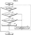
- FIG. 4 illustrates an example of a procedure of the brake control according to the present embodiment.
- the processing flow illustrated in FIG. 4 is performed at certain time intervals.
- the PCS-ECU 10 determines that there is a possibility of collision on the basis of TTC, specifically, for example, when TTC is equal to or smaller than a certain value (Yes at S1) and it is not during a prefill period (No at S2), control is performed to generate a certain deceleration or braking force in accordance with the instruction from the PCS-ECU 10 (S4).
- the process Upon completion of S4 and S5, the process returns to S1.
- the deceleration Dpf is an example of a third deceleration
- the deceleration Db is an example of a fourth deceleration.
- the present embodiment has described the example where the brake device 41 causes deceleration (applies braking force), but the braking force may be applied by the motor generator 62 or the engine 51 depending on the situation in each of the above-described steps.
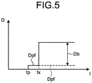
- FIG. 5 illustrates a change with time in a deceleration caused by a driver's operation of the brake pedal 43 in a period when the prefill operation is performed, that is, in a period from time tp to time ts1 in FIG. 2 .
- the brake controller 40d starts the prefill operation from time tp and gives to the brake device 41 an operational instruction for the deceleration Dpf.
- the driver operates the brake pedal 43 at time tx before time ts1 in FIG.
- the deceleration Dpp is an example of a first deceleration and the deceleration Dp is an example of a second deceleration.
- Dpf + Db the deceleration Dpf + Db
Landscapes
- Engineering & Computer Science (AREA)
- Transportation (AREA)
- Mechanical Engineering (AREA)
- Physics & Mathematics (AREA)
- General Physics & Mathematics (AREA)
- Regulating Braking Force (AREA)
Abstract
Description
- The present invention relates to a collision avoidance control device and a collision avoidance control method for a vehicle.
- Conventionally, there has been known a collision avoidance control device for a vehicle that controls the vehicle to avoid collision with an obstacle ahead based on data acquired in traveling (see, for example, Patent Document 1).
- Patent Document 1: Japanese Laid-open Patent Publication No.
2012-121534 - However, upon receiving a brake request from a driver through a brake pedal operation while a given deceleration is generated in the vehicle by the collision avoidance control, the collision avoidance control device for the vehicle as described above may give priority to the driver's brake request and stop the activation of the collision avoidance control. In this case, when resuming the collision avoidance control that has been stopped, the collision avoidance control device may fail to achieve an initially intended deceleration at the beginning of the control.
- It is an object of the present invention to provide a collision avoidance control device for a vehicle that can control the vehicle to achieve, for example, both an intended deceleration by collision avoidance control and a driver's intended deceleration.
- A collision avoidance control device for a vehicle according to the present invention comprises, for example, a determiner configured to determine whether to perform collision avoidance control to avoid collision with an obstacle ahead based on data acquired in traveling; and a brake controller configured to control, upon determination to perform the collision avoidance control by the determiner, at least a brake device to decelerate the vehicle at a first deceleration for a certain period and then to decelerate the vehicle at a second deceleration greater than the first deceleration, and to give an operational instruction to generate a third deceleration smaller than the first deceleration to the brake device before the certain period, wherein when receiving a brake request from a driver while the brake device is given the operational instruction corresponding to the third deceleration, the brake controller controls at least the brake device to decelerate the vehicle at a deceleration calculated by adding the third deceleration and a fourth deceleration corresponding to the brake request.
- According to the above-described collision avoidance control device for the vehicle, when receiving the driver's brake request while the brake device is given an operational instruction corresponding to the third deceleration before the certain period, the vehicle is controlled to decelerate at the deceleration calculated by adding the third deceleration and the fourth deceleration corresponding to the brake request from the driver. Thus, the above-described collision avoidance control device for the vehicle can perform collision avoidance control to produce the added deceleration even during the driver's operation, and can control the vehicle to achieve the deceleration intended by the driver's brake operation, for example.
- A collision avoidance control method for a vehicle according to the present invention causes a computer to perform, for example, determining whether to perform collision avoidance control to avoid collision with an obstacle ahead based on data acquired in traveling; controlling, upon determination to perform the collision avoidance control, at least a brake device to decelerate the vehicle at a first deceleration for a certain period and then to decelerate the vehicle at a second deceleration greater than the first deceleration; and giving an operational instruction to generate a third deceleration smaller than the first deceleration to the brake device before the certain period, wherein when receiving a brake request from a driver while the brake device is given the operational instruction corresponding to the third deceleration, at least the brake device is controlled to decelerate the vehicle at a deceleration calculated by adding the third deceleration and a fourth deceleration corresponding to the brake request.
- According to the above-described collision avoidance control method for the vehicle, when receiving the driver's brake request while the brake device is given an operational instruction corresponding to the third deceleration before the certain period, the vehicle is controlled to decelerate at the deceleration calculated by adding the third deceleration and the fourth deceleration corresponding to the brake request from the driver. Thus, the above-described collision avoidance control method for the vehicle can perform collision avoidance control to produce the added deceleration even during the driver's operation, and can control the vehicle to achieve the deceleration intended by the driver's brake operation, for example.
-
-
FIG. 1 is an exemplary schematic diagram illustrating a configuration of a vehicle in which a collision avoidance control device for the vehicle according to an embodiment is installed; -
FIG. 2 is an exemplary explanatory diagram illustrating transition of control state of the collision avoidance control device for the vehicle according to the embodiment; -
FIG. 3 is an exemplary schematic block diagram illustrating a brake electronic control unit (ECU) included in the collision avoidance control device for the vehicle according to the embodiment; -
FIG. 4 is an exemplary flowchart illustrating a control performed by the collision avoidance control device for the vehicle according to the embodiment; and -
FIG. 5 is a graph illustrating an example of a change with time in deceleration of the vehicle in the collision avoidance control device for the vehicle according to the embodiment. - An exemplary embodiment of the present invention will be described below. Configurations of the embodiment described below and functions and results (effects) brought by the configurations are presented for illustrative purposes only. The present invention can be implemented by other configurations than those disclosed in the embodiment below. The present invention can attain at least one of the effects (including derivative effects) that are brought by the configurations.
- The following describes, as an example, a situation that units/elements of a
vehicle 100 are controlled to avoid collision with an obstacle ahead while thevehicle 100 is traveling forward. -
FIG. 1 is an exemplary schematic view illustrating a configuration of thevehicle 100. As illustrated inFIG. 1 , thevehicle 100 includes, for example, anengine 51, a motor generator (M/G) 62, and abrake device 41. Theengine 51 and the motor generator 62 accelerate thevehicle 100. In this regard, theengine 51 and the motor generator 62 may be referred to as a propulsion source or propulsion device. Thevehicle 100 may include at least either theengine 51 or the motor generator 62 as its propulsion source. Acceleration of thevehicle 100 corresponds to an increase with time (time derivative) in velocity of thevehicle 100 traveling forward, and deceleration of thevehicle 100 corresponds to a decrease with time (time derivative) in velocity of thevehicle 100 traveling forward. In this regard, acceleration is also negative deceleration, and deceleration is also negative acceleration. In other words, as breaking force of thebrake device 41, that is, a deceleration decreases, an acceleration increases, whereas, as propulsion force of theengine 51 or the motor generator 62, that is, an acceleration decreases, a deceleration increases. - The
vehicle 100 includes a pre-crash safety electronic control unit (PCS-ECU) 10. When an obstacle is detected ahead of thevehicle 100, the PCS-ECU 10 determines whether there is a possibility of collision with the obstacle, on the basis of data acquired in traveling. When determining that collision is possible, the PCS-ECU 10 gives instructions to, for example, a brake ECU 40, anengine ECU 50, and a motor generator ECU (M/G ECU) 60 that control thebrake device 41, theengine 51, and the motor generator 62 to avoid collision with the obstacle. The PCS-ECU 10 is an example of a determiner. In the present embodiment, although the PCS-ECU 10 gives instructions for controlling the acceleration or deceleration of thevehicle 100, that is, propulsion force or braking force, the PCS-ECU 10 may also give instructions for controlling the steering of thevehicle 100. - The PCS-ECU 10 includes a control unit such as a central processing unit (CPU) or a controller, and storage units such as a read only memory (ROM), a random access memory (RAM), and a flash memory. The storage units may store therein, for example, a computer program for causing the PCS-ECU 10 to operate and data for use in arithmetic processing of the PCS-ECU 10.
- The
vehicle 100 includes a rangingdevice 21 and acamera 22. The rangingdevice 21 and thecamera 22 are examples of obstacle detectors. - The ranging
device 21 wirelessly and contactlessly measures a distance to the obstacle and is, for example, a radar device or a sonar device. The PCS-ECU 10 acquires from the rangingdevice 21 data indicating the distance to the obstacle. In this case, the data indicating the distance may be numeric data indicating the distance itself or data indicating a value corresponding to the distance. - The
camera 22 is a digital camera including an imaging device such as a charge-coupled device (CCD) or a CMOS image sensor (CIS). Thecamera 22 can output video data at a certain frame rate. The PCS-ECU 10 may acquire a distance to the obstacle by acquiring data indicating an image captured by thecamera 22 and using this image data. - Various sensors, which are not illustrated, are installed in the
vehicle 100 and data indicating sensing results is input from the sensors to the PCS-ECU 10. The sensors installed in thevehicle 100 may include sensors that output results of detection of the state of thevehicle 100. Examples of the sensors that output results of detection of the state of thevehicle 100 include a speed sensor, an accelerometer, and a gyro sensor. - The sensors installed in the
vehicle 100 may include sensors that output results of detection of an amount of operation or a required amount of operation of an operating element by the driver. Examples of the operating element to be operated by the driver include an accelerator pedal, a brake pedal, a brake handle, a steering wheel, and switches. - The sensors installed in the
vehicle 100 may include sensors that output results of detection of the states of any devices installed in thevehicle 100. Examples of the devices installed in thevehicle 100 include thebrake device 41, theengine 51, the motor generator 62, an inverter (IV) 61, a steering system, and a suspension system. Examples of physical quantities to be detected by the sensors installed in thevehicle 100 include distance, displacement, velocity, acceleration, rotational speed, angle, angular velocity, and angular acceleration. The PCS-ECU 10 may receive numerical data indicating each physical quantity itself, and may receive data indicating a value corresponding to a level or intensity of each physical quantity. - The data to input to the PCS-ECU 10 may be digital data, analogue data such as potential having no digitized value, or data that corresponds to not a value of a physical quantity but on/off states or individual phases.
- To perform collision avoidance control, the PCS-ECU 10 calculates an estimated time for the
vehicle 100 to collide with an obstacle ahead, that is, a time to collision (TTC). As a simplest example, the PCS-ECU 10 can calculate TTC by an expression:
vehicle 100 to the obstacle. TTC may be calculated in consideration of a relative acceleration of the obstacle and a deceleration of thevehicle 100. When, for example, TTC is equal to or smaller than a certain value, the PCS-ECU 10 can determine a possibility of collision. - The PCS-ECU 10 calculates the acceleration or deceleration of the
vehicle 100 for the collision avoidance control. The PCS-ECU 10 is an example of a collision avoidance controller. - The brake ECU 40 controls the
brake device 41 such that an acceleration or a deceleration set by the PCS-ECU 10 is achieved. The brake ECU 40 receives a signal indicating a value corresponding to a stroke of abrake pedal 43, that is, an amount of operation of thebrake pedal 43 from asensor 44. The brake ECU 40 is an example of a brake controller. Theengine ECU 50 controls theengine 51 such that an acceleration or a deceleration set by the PCS-ECU 10 is achieved. Themotor generator ECU 60 controls theinverter 61 such that the motor generator 62 operates to achieve an acceleration or a deceleration set by the PCS-ECU 10. - The brake ECU 40 can control a
stop lamp 42 mounted on the rear end of thevehicle 100 to light up. Lighting-up of thestop lamp 42 may be an indication of warning to the periphery of thevehicle 100, for example, to the vehicles behind. Ameter ECU 70 can control ameter 71 mounted on, for example, an instrument panel to display a warning. The display output of themeter 71 may work as an indication of warning to the driver or passengers in a vehicle cabin. Thestop lamp 42 and themeter 71 may be referred to as warning output devices, output devices, warning devices, or display output devices. An audible output may be output from a sound output device, which is not illustrated. The sound output device is, for example, a speaker or a buzzer, and may be referred to as a warning output device, output device, or warning device. -
FIG. 2 illustrates an example of transition of control state in an automatic collision avoidance control without a brake operation by the driver. In the graph inFIG. 2 , the horizontal axis represents time t and the vertical axis represents deceleration D. InFIG. 2 , the vertical axis represents required values of deceleration. - The PCS-ECU 10 calculates TTC at certain time intervals from data acquired during the travel of the
vehicle 100. In accordance with TTC values, the PCS-ECU 10 starts collision avoidance control, shifts the collision avoidance control to a next phase, or terminates the collision avoidance control. In other words, the PCS-ECU 10 monitors the situations relating to collision avoidance based on TTC. - First, the PCS-ECU 10 starts issuing a warning by means of, for example, the
meter 71 or a speaker. - Next, the PCS-ECU 10 gives an operational instruction to the brake ECU 40 to slightly decelerate the
vehicle 100 for a certain period. Thereby, the brake ECU 40 activates a pump (not illustrated) of thebrake device 41 to eliminate a gap between a brake pad and a rotor, a brake disc, or a drum. This operation may be referred to as brake prefill (PF). The pump is activated by the prefill operation, which increases responsiveness compared to a case in which braking force is increased from a non-activated state of the pump and also eliminates a gap or a dead stroke. This leads to increasing responsiveness of the start of the collision avoidance control. - The PCS-ECU 10 instructs the brake ECU 40 to perform a pre-brake operation for a certain period. Specifically, the PCS-ECU 10 transmits an instruction signal to the brake ECU 40 to illuminate the
stop lamp 42. The PCS-ECU 10 instructs the brake ECU 40 to attain, for example, a minimum deceleration (braking force) required for illuminating thestop lamp 42, and the brake ECU 40 controls thebrake device 41 as instructed. In the present embodiment, the main purpose of the pre-brake operation is to illuminate thestop lamp 42. The pre-brake operation may be set to produce a required deceleration that prompts the driver in a vehicle behind to perform a deceleration operation. The deceleration in the pre-brake operation is greater than that in the prefill operation. - The PCS-ECU 10 then instructs the brake ECU 40 to start brake control for avoiding collision. Specifically, the PCS-ECU 10 instructs the brake ECU 40 to change the velocity of the
vehicle 100 at a required deceleration, that is, to apply a required braking force to thevehicle 100, and the brake ECU 40 controls thebrake device 41 as instructed. In this brake control, the deceleration (braking force) may be increased incrementally. The deceleration in the brake control is greater than that in the prefill operation and the pre-brake operation. - When the
vehicle 100 stops without colliding with the obstacle, the PCS-ECU 10 instructs the brake ECU 40 to maintain thevehicle 100 in a stopped state for a certain period, and the brake ECU 40 controls thebrake device 41 as instructed. This operation may be referred to as brake hold (BH). - In the present embodiment, the PCS-ECU 10 can terminate the above-described collision avoidance control by a driver's operation of the acceleration pedal or the steering wheel, that is, through an acceleration request operation or a steering operation.
-
FIG. 3 illustrates an example of the brake ECU 40. The brake ECU 40 can implement various functions by performing processing in accordance with computer program(s) installed and loaded thereon. In other words, the brake ECU 40 can function, for example, as a data acquirer 40a, adeceleration acquirer 40b, anadder 40c, and abrake controller 40d by performing processing in accordance with the computer program(s). At least one of the functions of the above modules may be implemented by hardware. - The data acquirer 40a acquires data for use in the brake control. Examples of the data for use in the brake control may include data indicating a deceleration from the PCS-ECU 10, that is, a required deceleration, and include data from the
sensor 44 indicating an amount of operation of thebrake pedal 43. - The
deceleration acquirer 40b acquires a deceleration corresponding to an amount of operation of thebrake pedal 43, that is, a deceleration corresponding to a brake request from the driver. The deceleration acquired herein is irrelevant to the activation or non-activation of the collision avoidance control. In other words, the deceleration corresponding to the amount of operation of thebrake pedal 43 retains unchanged when the driver operates thebrake pedal 43 to brake in a normal situation with no activation of collision avoidance control and when the driver operates thebrake pedal 43 to brake during the collision avoidance control. Thedeceleration acquirer 40b acquires a deceleration corresponding to the amount of operation on the basis of, for example, data such as a map, a table, a mathematical function, or a mathematical expression stored in a storage included in the brake ECU 40. - Following the instruction from the PCS-ECU 10, the
adder 40c adds the deceleration by the prefill operation of the collision avoidance control and the deceleration corresponding to the brake request from the driver acquired by thedeceleration acquirer 40b. - The
brake controller 40d performs the PCS operation illustrated inFIG. 2 , that is, the above-described prefill, pre-brake, brake control, and brake hold operations under the collision avoidance control. When theadder 40c sums up the decelerations, thebrake controller 40d controls thebrake device 41 to decelerate thevehicle 100 at the deceleration obtained by the addition. Thebrake controller 40d can perform the brake control under vehicle behavior control different from the collision avoidance control. -
FIG. 4 illustrates an example of a procedure of the brake control according to the present embodiment. The processing flow illustrated inFIG. 4 is performed at certain time intervals. When the PCS-ECU 10 determines that there is a possibility of collision on the basis of TTC, specifically, for example, when TTC is equal to or smaller than a certain value (Yes at S1) and it is not during a prefill period (No at S2), control is performed to generate a certain deceleration or braking force in accordance with the instruction from the PCS-ECU 10 (S4). - With yes at S2, that is, when the
brake pedal 43 is not pressed during the prefill period or when the data acquirer 40a acquires no data indicating an amount of operation of thebrake pedal 43 and thedeceleration acquirer 40b acquires no deceleration corresponding to the amount of operation of the brake pedal 43 (No at S3), control by the PCS-ECU 10 is performed (S4). - With yes at S3, that is, when the
brake pedal 43 pressed, theadder 40c calculates a deceleration D by adding a deceleration Dpf in the prefill operation and a deceleration Db corresponding to the amount of operation of thebrake pedal 43, and thebrake controller 40d then controls thebrake device 41 to decelerate thevehicle 100 at the deceleration D obtained by the addition of "D = Dpf + Db" (S5). Upon completion of S4 and S5, the process returns to S1. The deceleration Dpf is an example of a third deceleration, and the deceleration Db is an example of a fourth deceleration. - The present embodiment has described the example where the
brake device 41 causes deceleration (applies braking force), but the braking force may be applied by the motor generator 62 or theengine 51 depending on the situation in each of the above-described steps. -
FIG. 5 illustrates a change with time in a deceleration caused by a driver's operation of thebrake pedal 43 in a period when the prefill operation is performed, that is, in a period from time tp to time ts1 inFIG. 2 . InFIG. 5 , thebrake controller 40d starts the prefill operation from time tp and gives to thebrake device 41 an operational instruction for the deceleration Dpf. When the driver operates thebrake pedal 43 at time tx before time ts1 inFIG. 2 , thebrake controller 40d controls thebrake device 41 to decelerate thevehicle 100 at the deceleration D = Dpf + Db, which is calculated by adding the deceleration Dpf and the deceleration Db corresponding to the amount of operation of thebrake pedal 43. Thereafter, as illustrated inFIG. 2 , thebrake controller 40d controls thebrake device 41 to decelerate thevehicle 100 at a deceleration Dpp from time ts1, and controls thebrake device 41 to decelerate thevehicle 100 at a deceleration Dp from time ts2. The deceleration Dpp is an example of a first deceleration and the deceleration Dp is an example of a second deceleration. - As described above, in the present embodiment, upon receiving a driver's brake request while the
vehicle 100 is decelerated at the deceleration Dpf (third deceleration) by the prefill operation, thebrake controller 40d controls thebrake device 41 to decelerate thevehicle 100 at the deceleration D = Dpf + Db, which is calculated by adding the deceleration Dpf by the prefill operation and the deceleration Db (fourth deceleration) corresponding to the driver's brake request. This enables thevehicle 100 to achieve both of a deceleration intended for the collision avoidance control and a deceleration intended by the driver. - While a certain embodiment has been described, the embodiment has been presented by way of example only, and is not intended to limit the scope of the inventions. Indeed, the novel embodiment described herein may be embodied in a variety of other forms; furthermore, various omissions, substitutions, combinations and changes in the form of the embodiment described herein may be made without departing from the spirit of the inventions. Various modifications can be made on specifications such as configurations, parts, numbers, time, velocity, and deceleration described in the embodiment to implement the present invention.
-
- 10
- PCS-ECU (determiner)
- 40
- Brake ECU (brake controller)
- 41
- Brake device
- 100
- Vehicle
Claims (2)
- A collision avoidance control device for a vehicle comprising:a determiner configured to determine whether to perform collision avoidance control to avoid collision with an obstacle ahead, based on data acquired in traveling; anda brake controller configuredto control, upon determination to perform the collision avoidance control by the determiner, at least a brake device to decelerate the vehicle at a first deceleration for a certain period and then to decelerate the vehicle at a second deceleration greater than the first deceleration, andto give an operational instruction to generate a third deceleration smaller than the first deceleration to the brake device before the certain period, whereinwhen receiving a brake request from a driver while the brake device is given the operational instruction corresponding to the third deceleration, the brake controller controls at least the brake device to decelerate the vehicle at a deceleration calculated by adding the third deceleration and a fourth deceleration corresponding to the brake request.
- A collision avoidance control method for a vehicle causing a computer to perform:determining whether to perform collision avoidance control to avoid collision with an obstacle ahead, based on data acquired in traveling;controlling, upon determination to perform the collision avoidance control, at least a brake device to decelerate the vehicle at a first deceleration for a certain period and then to decelerate the vehicle at a second deceleration greater than the first deceleration; andgiving an operational instruction to generate a third deceleration smaller than the first deceleration to the brake device before the certain period, whereinwhen receiving a brake request from a driver while the brake device is given the operational instruction corresponding to the third deceleration, at least the brake device is controlled to decelerate the vehicle at a deceleration calculated by adding the third deceleration and a fourth deceleration corresponding to the brake request.
Applications Claiming Priority (2)
| Application Number | Priority Date | Filing Date | Title |
|---|---|---|---|
| JP2015143478A JP6347447B2 (en) | 2015-07-17 | 2015-07-17 | Vehicle collision avoidance control device and collision avoidance control method |
| PCT/JP2016/070615 WO2017014113A1 (en) | 2015-07-17 | 2016-07-12 | Collision avoidance control device for vehicle, and a collision avoidance control method |
Publications (3)
| Publication Number | Publication Date |
|---|---|
| EP3326873A1 true EP3326873A1 (en) | 2018-05-30 |
| EP3326873A4 EP3326873A4 (en) | 2019-02-27 |
| EP3326873B1 EP3326873B1 (en) | 2021-10-20 |
Family
ID=57834877
Family Applications (1)
| Application Number | Title | Priority Date | Filing Date |
|---|---|---|---|
| EP16827673.1A Active EP3326873B1 (en) | 2015-07-17 | 2016-07-12 | Collision avoidance control device for vehicle, and a collision avoidance control method |
Country Status (5)
| Country | Link |
|---|---|
| US (1) | US10906515B2 (en) |
| EP (1) | EP3326873B1 (en) |
| JP (1) | JP6347447B2 (en) |
| CN (1) | CN107848502B (en) |
| WO (1) | WO2017014113A1 (en) |
Families Citing this family (5)
| Publication number | Priority date | Publication date | Assignee | Title |
|---|---|---|---|---|
| US10926695B1 (en) * | 2020-02-25 | 2021-02-23 | Stacey Johnson | Automotive safety brake light |
| JP7803058B2 (en) * | 2021-09-02 | 2026-01-21 | 株式会社アドヴィックス | Vehicle braking control device |
| CN116605200B (en) * | 2023-04-28 | 2025-09-09 | 中国第一汽车股份有限公司 | Emergency braking control method and device for vehicle, vehicle and storage medium |
| US20250018907A1 (en) * | 2023-07-11 | 2025-01-16 | Volvo Car Corporation | Predictive brake prefill for emergency braking |
| US20260048701A1 (en) * | 2024-08-13 | 2026-02-19 | Robert Bosch Gmbh | Providing advance warning of braking through early illumination of a brake light |
Family Cites Families (19)
| Publication number | Priority date | Publication date | Assignee | Title |
|---|---|---|---|---|
| JP2004189075A (en) | 2002-12-10 | 2004-07-08 | Denso Corp | Vehicle braking control device |
| US7018004B2 (en) * | 2003-12-18 | 2006-03-28 | Ford Global Technologies, Llc | System and method for brake pre-charging |
| JP4300365B2 (en) * | 2004-10-13 | 2009-07-22 | 日産自動車株式会社 | Vehicle braking force control device |
| JP2007118880A (en) | 2005-10-31 | 2007-05-17 | Toyota Motor Corp | Brake control device for vehicle |
| JP4869792B2 (en) * | 2006-06-02 | 2012-02-08 | 日野自動車株式会社 | Automatic braking control device |
| DE102008045481A1 (en) | 2008-08-28 | 2009-05-20 | Daimler Ag | Automatic emergency brake action triggering method for e.g. bus, involves implementing driver warning in form of partial brake actions of vehicle with predetermined, continuous increasing partial brake delay |
| FR2937936B1 (en) * | 2008-11-03 | 2011-09-02 | Valeo Vision Sas | DRIVING ASSISTANCE METHOD FOR MOTOR VEHICLE |
| DE102009038421B4 (en) * | 2009-08-21 | 2020-07-30 | Audi Ag | Motor vehicle |
| US8577550B2 (en) * | 2009-10-05 | 2013-11-05 | Ford Global Technologies, Llc | System for vehicle control to mitigate intersection collisions and method of using the same |
| DE102010027449A1 (en) | 2010-07-17 | 2012-01-19 | Man Truck & Bus Ag | Method for carrying out an emergency braking operation of a vehicle |
| DE102010049351A1 (en) | 2010-10-23 | 2012-04-26 | Daimler Ag | A method of operating a brake assist device and brake assist device for a vehicle |
| JP2012121534A (en) | 2010-12-10 | 2012-06-28 | Daimler Ag | Automatic braking device of vehicle |
| DE102011103936B4 (en) | 2011-06-10 | 2016-02-11 | Audi Ag | Method and device for braking a motor vehicle |
| WO2013065089A1 (en) | 2011-11-02 | 2013-05-10 | トヨタ自動車株式会社 | Braking control device |
| JP5796547B2 (en) * | 2012-06-13 | 2015-10-21 | 株式会社アドヴィックス | Vehicle travel support device |
| JP6119956B2 (en) * | 2012-10-10 | 2017-04-26 | 三菱自動車工業株式会社 | Vehicle danger avoidance support device |
| US20160280190A1 (en) * | 2015-03-23 | 2016-09-29 | Bendix Commercial Vehicle Systems Llc | Pre-computed and optionally cached collision mitigation braking system |
| JP6347448B2 (en) * | 2015-07-17 | 2018-06-27 | 株式会社アドヴィックス | Vehicle collision avoidance control device and collision avoidance control method |
| JP6302876B2 (en) * | 2015-07-17 | 2018-03-28 | 株式会社アドヴィックス | Vehicle collision avoidance control device and collision avoidance control method |
-
2015
- 2015-07-17 JP JP2015143478A patent/JP6347447B2/en active Active
-
2016
- 2016-07-12 EP EP16827673.1A patent/EP3326873B1/en active Active
- 2016-07-12 US US15/744,142 patent/US10906515B2/en active Active
- 2016-07-12 CN CN201680041015.XA patent/CN107848502B/en active Active
- 2016-07-12 WO PCT/JP2016/070615 patent/WO2017014113A1/en not_active Ceased
Also Published As
| Publication number | Publication date |
|---|---|
| EP3326873A4 (en) | 2019-02-27 |
| CN107848502A (en) | 2018-03-27 |
| US10906515B2 (en) | 2021-02-02 |
| JP6347447B2 (en) | 2018-06-27 |
| JP2017024495A (en) | 2017-02-02 |
| US20180201238A1 (en) | 2018-07-19 |
| WO2017014113A1 (en) | 2017-01-26 |
| EP3326873B1 (en) | 2021-10-20 |
| CN107848502B (en) | 2020-06-16 |
Similar Documents
| Publication | Publication Date | Title |
|---|---|---|
| EP3326874A1 (en) | Collision avoidance control device for vehicle, and a collision avoidance control method | |
| EP3326875B1 (en) | Collision avoidance control device for vehicle, and collision avoidance control method | |
| EP3326873B1 (en) | Collision avoidance control device for vehicle, and a collision avoidance control method | |
| CN105835819B (en) | Vehicle brake control apparatus | |
| US10710587B2 (en) | Electrcally-driven mining vehicle and brake operation guiding method in electrically-driven mining vehicle | |
| JP4412356B2 (en) | Vehicle collision mitigation device | |
| US10202121B2 (en) | Stop control device | |
| US9308914B1 (en) | Advanced driver assistance system for vehicle | |
| US10773647B2 (en) | Method for triggering an automatic emergency braking process with variable warning time period | |
| JP6547394B2 (en) | Vehicle braking control device | |
| KR101545054B1 (en) | Driver assistance systems and controlling method for the same | |
| US20190362632A1 (en) | Avoidance of Collision with Cross-Traffic | |
| EP3225474A1 (en) | Collision avoidance device | |
| US10029582B2 (en) | Method and device for operating a motor vehicle, motor vehicle | |
| CN1853210A (en) | Method and device for emitting warning | |
| WO2017014112A1 (en) | Collision avoidance control device for vehicle, and a collision avoidance control method | |
| KR20120052479A (en) | Apparatus for warning collision of vehicle and control method thereof | |
| JP5668706B2 (en) | BRAKE CONTROL DEVICE, BRAKE CONTROL METHOD, PROGRAM, AND MEDIUM | |
| KR101511863B1 (en) | Driver assistance systems and controlling method for the same | |
| RU2828924C1 (en) | Method and device for timely initiation of process of automatic emergency braking and control of longitudinal movement of vehicle | |
| WO2017014114A1 (en) | Vehicle collision avoidance control device and collision avoidance control method |
Legal Events
| Date | Code | Title | Description |
|---|---|---|---|
| STAA | Information on the status of an ep patent application or granted ep patent |
Free format text: STATUS: THE INTERNATIONAL PUBLICATION HAS BEEN MADE |
|
| PUAI | Public reference made under article 153(3) epc to a published international application that has entered the european phase |
Free format text: ORIGINAL CODE: 0009012 |
|
| STAA | Information on the status of an ep patent application or granted ep patent |
Free format text: STATUS: REQUEST FOR EXAMINATION WAS MADE |
|
| 17P | Request for examination filed |
Effective date: 20171215 |
|
| AK | Designated contracting states |
Kind code of ref document: A1 Designated state(s): AL AT BE BG CH CY CZ DE DK EE ES FI FR GB GR HR HU IE IS IT LI LT LU LV MC MK MT NL NO PL PT RO RS SE SI SK SM TR |
|
| AX | Request for extension of the european patent |
Extension state: BA ME |
|
| DAV | Request for validation of the european patent (deleted) | ||
| DAX | Request for extension of the european patent (deleted) | ||
| REG | Reference to a national code |
Ref country code: DE Ref legal event code: R079 Ref document number: 602016065233 Country of ref document: DE Free format text: PREVIOUS MAIN CLASS: B60T0007120000 Ipc: B60T0007220000 |
|
| A4 | Supplementary search report drawn up and despatched |
Effective date: 20190125 |
|
| RIC1 | Information provided on ipc code assigned before grant |
Ipc: B60T 8/00 20060101ALI20190121BHEP Ipc: B60T 7/22 20060101AFI20190121BHEP |
|
| RAP1 | Party data changed (applicant data changed or rights of an application transferred) |
Owner name: ADVICS CO., LTD. |
|
| GRAP | Despatch of communication of intention to grant a patent |
Free format text: ORIGINAL CODE: EPIDOSNIGR1 |
|
| STAA | Information on the status of an ep patent application or granted ep patent |
Free format text: STATUS: GRANT OF PATENT IS INTENDED |
|
| INTG | Intention to grant announced |
Effective date: 20210421 |
|
| GRAS | Grant fee paid |
Free format text: ORIGINAL CODE: EPIDOSNIGR3 |
|
| GRAA | (expected) grant |
Free format text: ORIGINAL CODE: 0009210 |
|
| STAA | Information on the status of an ep patent application or granted ep patent |
Free format text: STATUS: THE PATENT HAS BEEN GRANTED |
|
| RIN1 | Information on inventor provided before grant (corrected) |
Inventor name: IKE, WATARU Inventor name: OHMORI, YOSUKE Inventor name: NAKAGAWA, YUSUKE |
|
| RAP3 | Party data changed (applicant data changed or rights of an application transferred) |
Owner name: ADVICS CO., LTD. |
|
| AK | Designated contracting states |
Kind code of ref document: B1 Designated state(s): AL AT BE BG CH CY CZ DE DK EE ES FI FR GB GR HR HU IE IS IT LI LT LU LV MC MK MT NL NO PL PT RO RS SE SI SK SM TR |
|
| REG | Reference to a national code |
Ref country code: GB Ref legal event code: FG4D |
|
| RIN1 | Information on inventor provided before grant (corrected) |
Inventor name: IKE, WATARU Inventor name: OHMORI, YOSUKE Inventor name: NAKAGAWA, YUSUKE |
|
| REG | Reference to a national code |
Ref country code: CH Ref legal event code: EP |
|
| REG | Reference to a national code |
Ref country code: IE Ref legal event code: FG4D |
|
| REG | Reference to a national code |
Ref country code: DE Ref legal event code: R096 Ref document number: 602016065233 Country of ref document: DE |
|
| REG | Reference to a national code |
Ref country code: AT Ref legal event code: REF Ref document number: 1439685 Country of ref document: AT Kind code of ref document: T Effective date: 20211115 |
|
| REG | Reference to a national code |
Ref country code: LT Ref legal event code: MG9D |
|
| REG | Reference to a national code |
Ref country code: NL Ref legal event code: MP Effective date: 20211020 |
|
| REG | Reference to a national code |
Ref country code: AT Ref legal event code: MK05 Ref document number: 1439685 Country of ref document: AT Kind code of ref document: T Effective date: 20211020 |
|
| PG25 | Lapsed in a contracting state [announced via postgrant information from national office to epo] |
Ref country code: RS Free format text: LAPSE BECAUSE OF FAILURE TO SUBMIT A TRANSLATION OF THE DESCRIPTION OR TO PAY THE FEE WITHIN THE PRESCRIBED TIME-LIMIT Effective date: 20211020 Ref country code: LT Free format text: LAPSE BECAUSE OF FAILURE TO SUBMIT A TRANSLATION OF THE DESCRIPTION OR TO PAY THE FEE WITHIN THE PRESCRIBED TIME-LIMIT Effective date: 20211020 Ref country code: FI Free format text: LAPSE BECAUSE OF FAILURE TO SUBMIT A TRANSLATION OF THE DESCRIPTION OR TO PAY THE FEE WITHIN THE PRESCRIBED TIME-LIMIT Effective date: 20211020 Ref country code: BG Free format text: LAPSE BECAUSE OF FAILURE TO SUBMIT A TRANSLATION OF THE DESCRIPTION OR TO PAY THE FEE WITHIN THE PRESCRIBED TIME-LIMIT Effective date: 20220120 Ref country code: AT Free format text: LAPSE BECAUSE OF FAILURE TO SUBMIT A TRANSLATION OF THE DESCRIPTION OR TO PAY THE FEE WITHIN THE PRESCRIBED TIME-LIMIT Effective date: 20211020 |
|
| PG25 | Lapsed in a contracting state [announced via postgrant information from national office to epo] |
Ref country code: IS Free format text: LAPSE BECAUSE OF FAILURE TO SUBMIT A TRANSLATION OF THE DESCRIPTION OR TO PAY THE FEE WITHIN THE PRESCRIBED TIME-LIMIT Effective date: 20220220 Ref country code: SE Free format text: LAPSE BECAUSE OF FAILURE TO SUBMIT A TRANSLATION OF THE DESCRIPTION OR TO PAY THE FEE WITHIN THE PRESCRIBED TIME-LIMIT Effective date: 20211020 Ref country code: PT Free format text: LAPSE BECAUSE OF FAILURE TO SUBMIT A TRANSLATION OF THE DESCRIPTION OR TO PAY THE FEE WITHIN THE PRESCRIBED TIME-LIMIT Effective date: 20220221 Ref country code: PL Free format text: LAPSE BECAUSE OF FAILURE TO SUBMIT A TRANSLATION OF THE DESCRIPTION OR TO PAY THE FEE WITHIN THE PRESCRIBED TIME-LIMIT Effective date: 20211020 Ref country code: NO Free format text: LAPSE BECAUSE OF FAILURE TO SUBMIT A TRANSLATION OF THE DESCRIPTION OR TO PAY THE FEE WITHIN THE PRESCRIBED TIME-LIMIT Effective date: 20220120 Ref country code: NL Free format text: LAPSE BECAUSE OF FAILURE TO SUBMIT A TRANSLATION OF THE DESCRIPTION OR TO PAY THE FEE WITHIN THE PRESCRIBED TIME-LIMIT Effective date: 20211020 Ref country code: LV Free format text: LAPSE BECAUSE OF FAILURE TO SUBMIT A TRANSLATION OF THE DESCRIPTION OR TO PAY THE FEE WITHIN THE PRESCRIBED TIME-LIMIT Effective date: 20211020 Ref country code: HR Free format text: LAPSE BECAUSE OF FAILURE TO SUBMIT A TRANSLATION OF THE DESCRIPTION OR TO PAY THE FEE WITHIN THE PRESCRIBED TIME-LIMIT Effective date: 20211020 Ref country code: GR Free format text: LAPSE BECAUSE OF FAILURE TO SUBMIT A TRANSLATION OF THE DESCRIPTION OR TO PAY THE FEE WITHIN THE PRESCRIBED TIME-LIMIT Effective date: 20220121 Ref country code: ES Free format text: LAPSE BECAUSE OF FAILURE TO SUBMIT A TRANSLATION OF THE DESCRIPTION OR TO PAY THE FEE WITHIN THE PRESCRIBED TIME-LIMIT Effective date: 20211020 |
|
| REG | Reference to a national code |
Ref country code: DE Ref legal event code: R097 Ref document number: 602016065233 Country of ref document: DE |
|
| PG25 | Lapsed in a contracting state [announced via postgrant information from national office to epo] |
Ref country code: SM Free format text: LAPSE BECAUSE OF FAILURE TO SUBMIT A TRANSLATION OF THE DESCRIPTION OR TO PAY THE FEE WITHIN THE PRESCRIBED TIME-LIMIT Effective date: 20211020 Ref country code: SK Free format text: LAPSE BECAUSE OF FAILURE TO SUBMIT A TRANSLATION OF THE DESCRIPTION OR TO PAY THE FEE WITHIN THE PRESCRIBED TIME-LIMIT Effective date: 20211020 Ref country code: RO Free format text: LAPSE BECAUSE OF FAILURE TO SUBMIT A TRANSLATION OF THE DESCRIPTION OR TO PAY THE FEE WITHIN THE PRESCRIBED TIME-LIMIT Effective date: 20211020 Ref country code: EE Free format text: LAPSE BECAUSE OF FAILURE TO SUBMIT A TRANSLATION OF THE DESCRIPTION OR TO PAY THE FEE WITHIN THE PRESCRIBED TIME-LIMIT Effective date: 20211020 Ref country code: DK Free format text: LAPSE BECAUSE OF FAILURE TO SUBMIT A TRANSLATION OF THE DESCRIPTION OR TO PAY THE FEE WITHIN THE PRESCRIBED TIME-LIMIT Effective date: 20211020 Ref country code: CZ Free format text: LAPSE BECAUSE OF FAILURE TO SUBMIT A TRANSLATION OF THE DESCRIPTION OR TO PAY THE FEE WITHIN THE PRESCRIBED TIME-LIMIT Effective date: 20211020 |
|
| PLBE | No opposition filed within time limit |
Free format text: ORIGINAL CODE: 0009261 |
|
| STAA | Information on the status of an ep patent application or granted ep patent |
Free format text: STATUS: NO OPPOSITION FILED WITHIN TIME LIMIT |
|
| 26N | No opposition filed |
Effective date: 20220721 |
|
| PG25 | Lapsed in a contracting state [announced via postgrant information from national office to epo] |
Ref country code: AL Free format text: LAPSE BECAUSE OF FAILURE TO SUBMIT A TRANSLATION OF THE DESCRIPTION OR TO PAY THE FEE WITHIN THE PRESCRIBED TIME-LIMIT Effective date: 20211020 |
|
| PG25 | Lapsed in a contracting state [announced via postgrant information from national office to epo] |
Ref country code: SI Free format text: LAPSE BECAUSE OF FAILURE TO SUBMIT A TRANSLATION OF THE DESCRIPTION OR TO PAY THE FEE WITHIN THE PRESCRIBED TIME-LIMIT Effective date: 20211020 |
|
| PG25 | Lapsed in a contracting state [announced via postgrant information from national office to epo] |
Ref country code: MC Free format text: LAPSE BECAUSE OF FAILURE TO SUBMIT A TRANSLATION OF THE DESCRIPTION OR TO PAY THE FEE WITHIN THE PRESCRIBED TIME-LIMIT Effective date: 20211020 |
|
| REG | Reference to a national code |
Ref country code: CH Ref legal event code: PL |
|
| GBPC | Gb: european patent ceased through non-payment of renewal fee |
Effective date: 20220712 |
|
| REG | Reference to a national code |
Ref country code: BE Ref legal event code: MM Effective date: 20220731 |
|
| PG25 | Lapsed in a contracting state [announced via postgrant information from national office to epo] |
Ref country code: LU Free format text: LAPSE BECAUSE OF NON-PAYMENT OF DUE FEES Effective date: 20220712 Ref country code: LI Free format text: LAPSE BECAUSE OF NON-PAYMENT OF DUE FEES Effective date: 20220731 Ref country code: FR Free format text: LAPSE BECAUSE OF NON-PAYMENT OF DUE FEES Effective date: 20220731 Ref country code: CH Free format text: LAPSE BECAUSE OF NON-PAYMENT OF DUE FEES Effective date: 20220731 |
|
| PG25 | Lapsed in a contracting state [announced via postgrant information from national office to epo] |
Ref country code: IT Free format text: LAPSE BECAUSE OF FAILURE TO SUBMIT A TRANSLATION OF THE DESCRIPTION OR TO PAY THE FEE WITHIN THE PRESCRIBED TIME-LIMIT Effective date: 20211020 Ref country code: GB Free format text: LAPSE BECAUSE OF NON-PAYMENT OF DUE FEES Effective date: 20220712 Ref country code: BE Free format text: LAPSE BECAUSE OF NON-PAYMENT OF DUE FEES Effective date: 20220731 |
|
| PG25 | Lapsed in a contracting state [announced via postgrant information from national office to epo] |
Ref country code: IE Free format text: LAPSE BECAUSE OF NON-PAYMENT OF DUE FEES Effective date: 20220712 |
|
| PG25 | Lapsed in a contracting state [announced via postgrant information from national office to epo] |
Ref country code: HU Free format text: LAPSE BECAUSE OF FAILURE TO SUBMIT A TRANSLATION OF THE DESCRIPTION OR TO PAY THE FEE WITHIN THE PRESCRIBED TIME-LIMIT; INVALID AB INITIO Effective date: 20160712 |
|
| PG25 | Lapsed in a contracting state [announced via postgrant information from national office to epo] |
Ref country code: MK Free format text: LAPSE BECAUSE OF FAILURE TO SUBMIT A TRANSLATION OF THE DESCRIPTION OR TO PAY THE FEE WITHIN THE PRESCRIBED TIME-LIMIT Effective date: 20211020 Ref country code: CY Free format text: LAPSE BECAUSE OF FAILURE TO SUBMIT A TRANSLATION OF THE DESCRIPTION OR TO PAY THE FEE WITHIN THE PRESCRIBED TIME-LIMIT Effective date: 20211020 |
|
| PG25 | Lapsed in a contracting state [announced via postgrant information from national office to epo] |
Ref country code: MT Free format text: LAPSE BECAUSE OF FAILURE TO SUBMIT A TRANSLATION OF THE DESCRIPTION OR TO PAY THE FEE WITHIN THE PRESCRIBED TIME-LIMIT Effective date: 20211020 |
|
| PGFP | Annual fee paid to national office [announced via postgrant information from national office to epo] |
Ref country code: DE Payment date: 20250528 Year of fee payment: 10 |
|
| PG25 | Lapsed in a contracting state [announced via postgrant information from national office to epo] |
Ref country code: TR Free format text: LAPSE BECAUSE OF FAILURE TO SUBMIT A TRANSLATION OF THE DESCRIPTION OR TO PAY THE FEE WITHIN THE PRESCRIBED TIME-LIMIT Effective date: 20211020 |