WO2017014112A1 - Collision avoidance control device for vehicle, and a collision avoidance control method - Google Patents
Collision avoidance control device for vehicle, and a collision avoidance control method Download PDFInfo
- Publication number
- WO2017014112A1 WO2017014112A1 PCT/JP2016/070614 JP2016070614W WO2017014112A1 WO 2017014112 A1 WO2017014112 A1 WO 2017014112A1 JP 2016070614 W JP2016070614 W JP 2016070614W WO 2017014112 A1 WO2017014112 A1 WO 2017014112A1
- Authority
- WO
- WIPO (PCT)
- Prior art keywords
- deceleration
- vehicle
- collision avoidance
- ecu
- control
- Prior art date
Links
Images


Classifications
-
- B—PERFORMING OPERATIONS; TRANSPORTING
- B60—VEHICLES IN GENERAL
- B60R—VEHICLES, VEHICLE FITTINGS, OR VEHICLE PARTS, NOT OTHERWISE PROVIDED FOR
- B60R21/00—Arrangements or fittings on vehicles for protecting or preventing injuries to occupants or pedestrians in case of accidents or other traffic risks
-
- B—PERFORMING OPERATIONS; TRANSPORTING
- B60—VEHICLES IN GENERAL
- B60T—VEHICLE BRAKE CONTROL SYSTEMS OR PARTS THEREOF; BRAKE CONTROL SYSTEMS OR PARTS THEREOF, IN GENERAL; ARRANGEMENT OF BRAKING ELEMENTS ON VEHICLES IN GENERAL; PORTABLE DEVICES FOR PREVENTING UNWANTED MOVEMENT OF VEHICLES; VEHICLE MODIFICATIONS TO FACILITATE COOLING OF BRAKES
- B60T7/00—Brake-action initiating means
- B60T7/12—Brake-action initiating means for automatic initiation; for initiation not subject to will of driver or passenger
-
- B—PERFORMING OPERATIONS; TRANSPORTING
- B60—VEHICLES IN GENERAL
- B60W—CONJOINT CONTROL OF VEHICLE SUB-UNITS OF DIFFERENT TYPE OR DIFFERENT FUNCTION; CONTROL SYSTEMS SPECIALLY ADAPTED FOR HYBRID VEHICLES; ROAD VEHICLE DRIVE CONTROL SYSTEMS FOR PURPOSES NOT RELATED TO THE CONTROL OF A PARTICULAR SUB-UNIT
- B60W30/00—Purposes of road vehicle drive control systems not related to the control of a particular sub-unit, e.g. of systems using conjoint control of vehicle sub-units, or advanced driver assistance systems for ensuring comfort, stability and safety or drive control systems for propelling or retarding the vehicle
- B60W30/08—Active safety systems predicting or avoiding probable or impending collision or attempting to minimise its consequences
- B60W30/09—Taking automatic action to avoid collision, e.g. braking and steering
-
- G—PHYSICS
- G08—SIGNALLING
- G08G—TRAFFIC CONTROL SYSTEMS
- G08G1/00—Traffic control systems for road vehicles
- G08G1/16—Anti-collision systems
Definitions
- the present invention relates to a vehicle collision avoidance control device and a collision avoidance control method.
- Patent Document 1 a collision avoidance control device for a vehicle that performs control for avoiding a collision with an obstacle ahead based on data acquired during traveling is known.
- one of the problems of the present invention is to obtain a vehicle collision avoidance control apparatus that can more smoothly execute a transition from vehicle behavior different from collision avoidance to collision avoidance, for example.
- the vehicle collision avoidance control apparatus includes, for example, a determination unit that determines whether or not to execute collision avoidance control with an obstacle ahead based on data acquired during traveling, and When the execution of the collision avoidance control is determined by the vehicle behavior control unit that controls at least one of the drive device and the brake device and the determination unit so that a behavior different from the collision avoidance with an object occurs, a predetermined period of time
- a braking control unit that controls at least a brake device so that the vehicle decelerates at a second deceleration larger than the first deceleration after the vehicle decelerates at the first deceleration at
- the control unit is configured to avoid the collision by the determination unit while the vehicle behavior control unit controls at least one of the drive device and the brake device so that the vehicle decelerates at the third deceleration. If the execution is determined, the vehicle decelerates at the second deceleration after the vehicle decelerates at a large one of the first deceleration and the third deceleration during the predetermined period.
- the vehicle deceleration After the vehicle is decelerating at the third deceleration in a vehicle behavior different from collision avoidance, the vehicle decelerates to the first deceleration of collision avoidance that is smaller than the third deceleration, and then from the first deceleration Change to the second deceleration for avoiding large collisions, the deceleration changes rapidly and frequently from the third to the first and from the first to the second.
- the vehicle deceleration is set to the larger one of the first deceleration and the third deceleration, and then changes to the second deceleration.
- the change in deceleration becomes smoother.
- the vehicle behavior control unit determines that the third deceleration is In a state larger than the first deceleration, the vehicle is controlled to decelerate at the third deceleration. Therefore, according to the vehicle collision avoidance control apparatus, for example, even when the third deceleration decreases with the passage of time, the vehicle collision avoidance is reduced when the vehicle behavior is changed from collision avoidance to collision avoidance. The speed change becomes smoother.
- the computer determines whether or not to execute collision avoidance control with an obstacle ahead based on data acquired during traveling, and the collision
- the execution of the avoidance control is determined, at least the brake device so that the vehicle decelerates at the second deceleration larger than the first deceleration after the vehicle decelerates at the first deceleration for a predetermined period.
- the collision avoidance is performed in a state where at least one of the drive device and the brake device is controlled so that the vehicle decelerates at the third deceleration in a vehicle behavior different from the avoidance of the collision with the obstacle.
- the vehicle decelerates at the second deceleration after the vehicle decelerates at a large one of the first deceleration and the third deceleration during the predetermined period.
- the brake device At least the brake device.
- the vehicle After the vehicle is decelerating at the third deceleration in a vehicle behavior different from collision avoidance, the vehicle decelerates to the first deceleration of collision avoidance that is smaller than the third deceleration, and then from the first deceleration Change to the second deceleration for avoiding large collisions, the deceleration changes rapidly and frequently from the third to the first and from the first to the second.
- the collision avoidance control method for a vehicle since the larger one of the first deceleration and the third deceleration is selected and then changed to the second deceleration, it is different from the collision avoidance.
- the change in deceleration becomes smoother.
- FIG. 1 is an exemplary schematic diagram of a vehicle on which the collision avoidance control device for a vehicle according to the embodiment is mounted.
- FIG. 2 is an exemplary explanatory diagram illustrating transition of the control state by the vehicle collision avoidance control device of the embodiment.
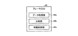
- FIG. 3 is an exemplary schematic block diagram of a brake ECU included in the collision avoidance control device for a vehicle according to the embodiment.
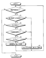
- FIG. 4 is an exemplary flowchart of control by the vehicle collision avoidance control device of the embodiment.
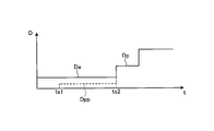
- FIG. 5 is a graph showing an example of a change over time in the deceleration of the vehicle when the vehicle behavior is different from the collision avoidance to the collision avoidance in the vehicle collision avoidance control apparatus of the embodiment.
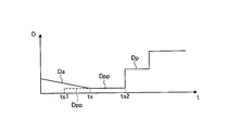
- FIG. 6 is a graph showing another example of the change over time in the deceleration of the vehicle when the vehicle behavior is different from the collision avoidance to the collision avoidance in the vehicle collision avoidance control apparatus of the embodiment.
- each part of the vehicle 100 is controlled to avoid a collision with an obstacle ahead while the vehicle 100 is traveling forward is illustrated.
- FIG. 1 is an exemplary and schematic configuration diagram of the vehicle 100.
- the vehicle 100 includes an engine 51, a motor generator 62 (M / G), a brake device 41, and the like.
- Engine 51 and motor generator 62 cause acceleration of vehicle 100. Therefore, the engine 51 and the motor generator 62 can also be referred to as drive sources or drive devices.
- the vehicle 100 only needs to be equipped with at least one of the engine 51 and the motor generator 62 as a drive source. Further, the acceleration of the vehicle 100 is an increase over time of the speed toward the front of the vehicle 100 (time differentiation), and the deceleration of the vehicle 100 is a decrease over time of the speed toward the front of the vehicle 100 (time differentiation). ).
- the acceleration is also a negative deceleration
- the deceleration is also a negative acceleration. That is, the acceleration increases when the braking force or deceleration by the brake device 41 decreases, and the deceleration increases when the driving force or acceleration by the engine 51 or the motor generator 62 decreases.
- the vehicle 100 includes a PCS-ECU 10 (pre-crash safety electronic control unit).
- the PCS-ECU 10 detects that there is an obstacle ahead of the vehicle 100 based on the data acquired during traveling, the PCS-ECU 10 determines whether or not there is a possibility of a collision with the obstacle.
- the brake ECU 41 that controls the brake device 41, the engine 51, the motor generator 62, etc.
- the engine ECU 50 the M / GECU 60 (motor generator ECU), etc.
- the PCS-ECU 10 is an example of a determination unit.
- the PCS-ECU 10 instructs to control the acceleration or deceleration of the vehicle 100, that is, the driving force or the braking force, but the PCS-ECU 10 further instructs to control the steering of the vehicle 100. May be.
- the PCS-ECU 10 includes a control unit such as a CPU (central processing unit) and a controller, and a storage unit such as a ROM (read only memory), a RAM (random access memory), and a flash memory.
- the storage unit can store a program for operating the PCS-ECU 10, data used for arithmetic processing of the PCS-ECU 10, and the like.
- the vehicle 100 is equipped with a distance measuring device 21 and a camera 22.
- the distance measuring device 21 and the camera 22 are an example of an obstacle detection unit.
- the distance measuring device 21 is a device that wirelessly measures the distance to the obstacle without contact, and is, for example, a radar device or a sonar device.
- the PCS-ECU 10 acquires data indicating the distance from the obstacle from the distance measuring device 21.
- the data indicating the distance may be numerical data indicating the distance itself, or may be data having a value corresponding to the distance.
- the camera 22 is a digital camera incorporating an image sensor such as a CCD (charge coupled device) or a CIS (CMOS image sensor).
- the camera 22 can output moving image data at a predetermined frame rate.
- the PCS-ECU 10 may acquire data indicating an image captured by the camera 22 and acquire the distance to the obstacle using the image data.
- PCS-ECU 10 receives data indicating detection results from the various sensors from various sensors mounted on vehicle 100.
- the sensor mounted on the vehicle 100 may include a sensor that indicates a detection result of the state of the vehicle 100.
- Sensors indicating the detection result of the state of the vehicle 100 are, for example, a vehicle speed sensor, an acceleration sensor, a gyro sensor, and the like.
- the sensor mounted on the vehicle 100 may include a sensor that indicates a detection result of an operation amount or an operation request amount in an operation unit operated by a driver.
- the operation unit by the driver is, for example, an accelerator pedal, a brake pedal, a brake handle, a steering wheel, a switch, or the like.
- the sensor mounted on the vehicle 100 may include a sensor that indicates the detection result of the state of each device mounted on the vehicle 100.
- Devices mounted on the vehicle 100 are, for example, a brake device 41, an engine 51, a motor generator 62, an inverter 61 (IV), a steering system, a suspension system, and the like.
- the physical quantities detected by various sensors mounted on the vehicle 100 are, for example, distance, displacement, speed, acceleration, rotational speed, angle, angular velocity, angular acceleration, and the like.
- the PCS-ECU 10 may be input with numerical data indicating each physical quantity itself, or may be input with data corresponding to the magnitude of each physical quantity.
- the data input to the PCS-ECU 10 may be digital data, analog data such as non-numerical potentials, or data corresponding to on / off and stages instead of physical values. There may be.
- the PCS-ECU 10 calculates a predicted time to collide with an obstacle ahead, that is, TTC (time to collision) when performing collision avoidance control.
- TTC time to collision
- the TTC may be calculated in consideration of the relative acceleration of the obstacle, the deceleration of the vehicle 100, and the like. For example, the PCS-ECU 10 can determine that there is a possibility of a collision when the TTC is equal to or less than a predetermined value.
- the PCS-ECU 10 calculates the acceleration or deceleration of the vehicle 100 when performing collision avoidance control.
- the PCS-ECU 10 is an example of a collision avoidance control unit, and is also an example of a first collision avoidance control unit.
- the brake ECU 40 controls the brake device 41 so that the acceleration or deceleration set by the PCS-ECU 10 can be obtained.
- the brake ECU 40 is an example of a braking control unit.
- the engine ECU 50 controls the engine 51 so that the acceleration or deceleration set by the PCS-ECU 10 can be obtained.
- the M / GECU 60 controls the inverter 61 so that the motor generator 62 operates so that the acceleration or deceleration set by the PCS-ECU 10 can be obtained.
- the brake ECU 40 can control the stop lamp 42 provided at the rear end of the vehicle 100 to light up.
- the lighting of the stop lamp 42 can be an alarm display for the surroundings of the vehicle 100, for example, the following vehicle.
- meter ECU70 can control the meter 71 provided in the instrument panel etc. so that a warning display may be output.
- the display output of the meter 71 can be an alarm display for the driver and passengers in the passenger compartment.
- the stop lamp 42 and the meter 71 can also be referred to as an alarm output device, an output device, an alarm device, a display output device, or the like.
- an audio output can be output from an audio output device (not shown).
- the audio output device is, for example, a speaker or a buzzer, and can also be called an alarm output device, an output device, an alarm device, or the like.
- the ACC (adaptive cruise control) -ECU 31 is, for example, a drive device, that is, the engine 51 or the motor generator 62, the brake ECU 40 that controls the brake device 41, the engine ECU 50, and the M so that the vehicle 100 travels at a set speed. / GECU 60 can be instructed. Further, for example, the ACC-ECU 31 controls the drive device and the brake device 41 so as to realize automatic traveling and automatic tracking to follow the vehicle traveling ahead while maintaining the inter-vehicle distance with the vehicle traveling forward.
- the brake ECU 40, the engine ECU 50, the M / GECU 60, and the like may be instructed.
- the ACC-ECU 31 is an example of a vehicle behavior control unit that controls each part of the vehicle 100 so that a vehicle behavior different from the collision avoidance by the PCS-ECU 10 occurs.
- FIG. 1 the connection between the ACC-ECU 31 and the engine ECU 50, the M / GECU 60, or the like is not shown.
- IPA (intelligent parking assist) -ECU 32 constitutes a parking assistance system.
- the IPA-ECU 32 controls a steering device (not shown) so that the vehicle 100 moves to a target position (parking position) along a predetermined route, and drives and a brake device 41 so that the speed of the vehicle 100 is maintained. Can be instructed to the brake ECU 40, the engine ECU 50, the M / GECU 60, and the like.
- the IPA-ECU 32 is also an example of a vehicle behavior control unit. In FIG. 1, the connection between the IPA-ECU 32 and the engine ECU 50, the M / GECU 60, etc. is not shown.
- ICS-ECU 33 constitutes a second collision prevention system.
- the ICS-ECU 33 controls a display or a speaker (not shown) so that a warning by display or sound is output when approaching an obstacle, and the obstacle is detected within a predetermined distance.
- the operation of the driving device is restricted by an instruction to the engine ECU 50, the M / GECU 60, etc. to suppress the movement of the vehicle 100, and an obstacle is detected within a predetermined distance during the movement of the vehicle 100. Instructs the brake ECU 40 that controls the brake device 41 to prevent a collision with the obstacle.
- the ICS-ECU 33 is also an example of a vehicle behavior control unit.
- the ICS-ECU 33 is also an example of a second collision avoidance control unit.
- the PCS-ECU 10, ACC-ECU 31, IPA-ECU 32, ICS-ECU 33, and brake ECU 40 are included in the collision avoidance control device.
- FIG. 1 the connection between the ICS-ECU 33 and the engine ECU 50, the M / GECU 60, etc. is not shown.
- FIG. 2 shows an example of the transition of the control state in the automatic collision avoidance control when the driver does not perform the brake operation.
- the horizontal axis represents time t and the vertical axis represents deceleration D.
- the vertical axis in FIG. 2 is the required deceleration value.
- the PCS-ECU 10 calculates TTC at predetermined time intervals based on data acquired while the vehicle 100 is traveling, and starts collision avoidance control or performs collision avoidance control according to this TTC value. To the next stage, or the collision avoidance control is terminated. That is, the PCS-ECU 10 monitors the situation related to collision avoidance based on the TTC.
- the PCS-ECU 10 starts an alarm operation by the meter 71 or a speaker.
- the PCS-ECU 10 instructs the brake ECU 40 to start preliminary braking. Specifically, the PCS-ECU 10 transmits an instruction signal to the brake ECU 40 so that the stop lamp 42 is lit. Further, for example, the PCS-ECU 10 instructs the brake ECU 40 to obtain the minimum necessary deceleration (braking force) accompanying the lighting of the stop lamp 42, and the brake ECU 40 controls the brake device 41 based on the instruction. .
- the main purpose of the preliminary braking is to turn on the stop lamp 42, but a required deceleration that makes the driver of the rear vehicle aware of the deceleration operation may be obtained.
- the PCS-ECU 10 instructs the brake ECU 40 to start braking control for the purpose of avoiding a collision. Specifically, the PCS-ECU 10 instructs the brake ECU 40 to change the speed of the vehicle 100 at a required deceleration, that is, to obtain a required braking force, and the brake ECU 40 determines a brake device based on the instruction. 41 is controlled. In the braking control, the deceleration (braking force) may increase stepwise. The deceleration in the braking control is larger than the deceleration in the preliminary braking.
- the PCS-ECU 10 instructs the brake ECU 40 to maintain the stopped state for a predetermined period, and the brake ECU 40 controls the brake device 41 based on the instruction. To do.
- This operation can also be referred to as a brake hold (BH).
- the PCS-ECU 10 can end the above-described collision avoidance control by an operation of an accelerator pedal or a steering wheel by the driver, that is, an acceleration request operation, a steering operation, or the like.
- FIG. 2 shows a change with time of the deceleration D in a state where the vehicle 100 is not controlled to decelerate in a vehicle behavior different from the collision avoidance control.
- the collision avoidance control is started, that is, the collision avoidance.
- control different from FIG. 2 is executed so that the deceleration changes more smoothly.
- a processing unit for changing the deceleration more smoothly is mounted on the brake ECU 40.
- FIG. 3 shows an example of the brake ECU 40.
- the brake ECU 40 can execute processing according to the installed and loaded program to realize each function. That is, by executing the process according to the program, the brake ECU 40 can function as the data acquisition unit 40a, the comparison unit 40b, the braking control unit 40c, and the like. Note that at least some of the functions of the above-described units may be realized by hardware.
- the data acquisition unit 40a can acquire data used for braking control.
- the data used for the braking control includes data indicating the deceleration obtained from the PCS-ECU 10, ACC-ECU 31, IPA-ECU 32, ICS-ECU 33, and the like.
- the comparison unit 40b executes the preliminary braking when the vehicle 100 is decelerated in the vehicle behavior different from the collision avoidance control by the PCS-ECU 10 before the start of the preliminary braking, that is, before the time ts1 in FIG. 2, that is, the data indicating the deceleration obtained from the PCS-ECU 10 and the ACC-ECU 31, IPA-ECU 32, or ICS-ECU 33 during the period (predetermined period) from time ts1 to time ts2 in FIG. Compared with the data indicating the measured deceleration.
- the braking control unit 40c performs the above-described preliminary braking, braking control, and brake hold in the PCS operation of FIG. 2, that is, collision avoidance control. Further, the braking control unit 40c executes braking in a vehicle behavior different from the collision avoidance control, that is, in ACC, IPA, or ICS. Note that the control for causing the vehicle behavior different from the collision avoidance control may be simply referred to as other control hereinafter.
- FIG. 4 shows an example of a braking control procedure according to this embodiment.
- the flow shown in FIG. 4 is executed at predetermined time intervals.
- the PCS-ECU 10 determines that there is a possibility of a collision based on the TTC, specifically, for example, when the TTC is equal to or less than a predetermined value (Yes in S1), the vehicle is different from the collision avoidance control.
- the vehicle is not decelerating in the behavior, that is, ACC, IPA, ICS, that is, when other control is not being executed, when the vehicle 100 is controlled to travel at a constant speed by another control, or other
- the control is executed based on an instruction from the PCS-ECU 10 (S7).
- the comparison by the comparison unit 40b in FIG. 3 is performed. That is, the comparison unit 40b compares the deceleration Dpp of preliminary braking by the PCS-ECU 10 with the deceleration Da by other control (S5).
- the braking control unit 40c controls the brake device 41 so that the vehicle 100 decelerates according to the deceleration Da, that is, at the deceleration Da. (S6).
- the deceleration Da is an example of a third deceleration
- the deceleration Dpp is an example of a first deceleration.
- FIG. 5 shows a case where it is determined that there is a possibility of a collision when the vehicle 100 is controlled to decelerate at the deceleration Da by other control, and when Da> Dpp.
- the change in speed over time is shown.
- the deceleration D of the vehicle 100 shifts from the deceleration Da in the other control to the deceleration Dp in the braking control without shifting to the deceleration Dpp in the preliminary braking. Therefore, compared with the case where the deceleration D of the vehicle 100 decreases from Da to Dpp and further increases to Dp, the frequency of change of the deceleration D is lower and the range of change of the deceleration D is smaller.
- the deceleration Dp is an example of a second deceleration.
- FIG. 6 shows an example different from FIG. 5 when it is determined that there is a possibility of collision when the vehicle 100 is controlled to decelerate at the deceleration Da by other control.
- Da Dpp at time tx.
- the deceleration D of the vehicle 100 becomes the deceleration Da in other control, and after time tx, the deceleration in the collision avoidance control by the PCS-ECU 10
- the speeds Dpp and Dp are obtained. Therefore, for example, compared with a case where the deceleration D of the vehicle 100 decreases from Da to Dpp at time ts1, a sudden change in the deceleration D is suppressed.
- the deceleration D is the deceleration Da (third deceleration) by other control and the deceleration Dpp (first deceleration) in the preliminary braking of the collision avoidance control.
- the speed changes to the deceleration Dp (second deceleration) in the braking control of the collision avoidance control. Therefore, when the vehicle behavior is different from the collision avoidance, the deceleration D is changed. Changes more smoothly.
- the deceleration D is changed from the deceleration Da to the preliminary braking. Since the transition to the deceleration Dpp is performed without a step, the transition of the deceleration D becomes smoother when shifting from the vehicle behavior different from the collision avoidance to the collision avoidance.
- SYMBOLS 10 ... PCS-ECU (determination part), 31 ... ACC-ECU (vehicle behavior control part), 32 ... IPA-ECU (vehicle behavior control part), 33 ... ICS-ECU (vehicle behavior control part), 40 ... Brake ECU (Braking control part), 41 ... brake device, 51 ... engine (drive device), 62 ... motor generator (drive device), 100 ... vehicle.
Abstract
In this collision avoidance control device for a vehicle, if a determination unit determines to carry out collision avoidance control in a state in which a vehicle behavior control unit is controlling a drive device and/or a braking device such that the vehicle decelerates at a third deceleration, a braking control unit controls at least the braking device such that, after the vehicle has decelerated during a prescribed period at a first deceleration or a third deceleration, whichever is greater, the vehicle decelerates at a second deceleration greater than the first deceleration.
Description
本発明は、車両の衝突回避制御装置および衝突回避制御方法に関する。
The present invention relates to a vehicle collision avoidance control device and a collision avoidance control method.
従来、走行中に取得されたデータに基づいて前方の障害物との衝突を回避する制御を行う車両の衝突回避制御装置が知られている(例えば、特許文献1)。
Conventionally, a collision avoidance control device for a vehicle that performs control for avoiding a collision with an obstacle ahead based on data acquired during traveling is known (for example, Patent Document 1).
この種の車両の衝突回避制御装置では、衝突回避とは異なる車両挙動のために車両が減速するよう制御されている状態で、衝突回避制御が開始された場合に、例えば、車両の減速度が急激に変化したり頻繁に変化したりするのは好ましくない。特に、障害物との距離が接近している状態で減速度が急に減少するような変化は、運転者にとって好ましくない。
In this type of vehicle collision avoidance control device, when the collision avoidance control is started in a state where the vehicle is controlled to decelerate due to a vehicle behavior different from collision avoidance, for example, the vehicle deceleration is reduced. It is not preferable to change suddenly or change frequently. In particular, a change in which the deceleration suddenly decreases while the distance to the obstacle is close is not preferable for the driver.
そこで、本発明の課題の一つは、例えば、衝突回避とは異なる車両挙動から衝突回避への移行がより円滑に実行されうる車両の衝突回避制御装置を得ることである。
Therefore, one of the problems of the present invention is to obtain a vehicle collision avoidance control apparatus that can more smoothly execute a transition from vehicle behavior different from collision avoidance to collision avoidance, for example.
本発明の車両の衝突回避制御装置は、例えば、走行中に取得されたデータに基づいて、前方の障害物との衝突回避制御を実行するか否かを判断する判断部と、車両に上記障害物との衝突回避とは異なる挙動が生じるよう、駆動装置およびブレーキ装置のうち少なくとも一方を制御する車両挙動制御部と、上記判断部によって上記衝突回避制御の実行が判断された場合に、所定期間において車両が第一の減速度で減速した後、車両が上記第一の減速度よりも大きい第二の減速度で減速するよう、少なくともブレーキ装置を制御する制動制御部と、を備え、上記制動制御部は、車両が第三の減速度で減速するよう上記車両挙動制御部が駆動装置およびブレーキ装置のうち少なくとも一方を制御している状態で、上記判断部によって上記衝突回避制御の実行が判断された場合には、上記所定期間において車両が上記第一の減速度および上記第三の減速度のうち大きい減速度で減速した後、車両が上記第二の減速度で減速するよう、少なくともブレーキ装置を制御する。
The vehicle collision avoidance control apparatus according to the present invention includes, for example, a determination unit that determines whether or not to execute collision avoidance control with an obstacle ahead based on data acquired during traveling, and When the execution of the collision avoidance control is determined by the vehicle behavior control unit that controls at least one of the drive device and the brake device and the determination unit so that a behavior different from the collision avoidance with an object occurs, a predetermined period of time A braking control unit that controls at least a brake device so that the vehicle decelerates at a second deceleration larger than the first deceleration after the vehicle decelerates at the first deceleration at The control unit is configured to avoid the collision by the determination unit while the vehicle behavior control unit controls at least one of the drive device and the brake device so that the vehicle decelerates at the third deceleration. If the execution is determined, the vehicle decelerates at the second deceleration after the vehicle decelerates at a large one of the first deceleration and the third deceleration during the predetermined period. At least the brake device is controlled.
衝突回避とは異なる車両挙動において車両が第三の減速度で減速している状態から、第三の減速度よりも小さい衝突回避の第一の減速度に減速した後、第一の減速度よりも大きい衝突回避の第二の減速度に変化すると、減速度が第三から第一、そして第一から第二へと急激かつ頻繁に変化してしまう。この点、上記車両の衝突回避制御装置によれば、車両の減速度は、第一の減速度と第三の減速度のうち大きい方に設定された後、第二の減速度に変化するため、衝突回避とは異なる車両挙動から衝突回避へ移行する際に、減速度の変化がより円滑になる。
After the vehicle is decelerating at the third deceleration in a vehicle behavior different from collision avoidance, the vehicle decelerates to the first deceleration of collision avoidance that is smaller than the third deceleration, and then from the first deceleration Change to the second deceleration for avoiding large collisions, the deceleration changes rapidly and frequently from the third to the first and from the first to the second. In this regard, according to the vehicle collision avoidance control apparatus, the vehicle deceleration is set to the larger one of the first deceleration and the third deceleration, and then changes to the second deceleration. When shifting from vehicle behavior different from collision avoidance to collision avoidance, the change in deceleration becomes smoother.
また、上記車両の衝突回避制御装置では、例えば、上記車両挙動制御部は、上記所定期間内で上記第三の減速度が時間の経過とともに減少する場合には、上記第三の減速度が上記第一の減速度よりも大きい状態では、車両が上記第三の減速度で減速するよう制御する。よって、上記車両の衝突回避制御装置によれば、例えば、第三の減速度が時間の経過とともに減少するような場合にも、衝突回避とは異なる車両挙動から衝突回避へ移行する際に、減速度の変化がより円滑になる。
In the vehicle collision avoidance control device, for example, when the third deceleration decreases with the passage of time within the predetermined period, the vehicle behavior control unit determines that the third deceleration is In a state larger than the first deceleration, the vehicle is controlled to decelerate at the third deceleration. Therefore, according to the vehicle collision avoidance control apparatus, for example, even when the third deceleration decreases with the passage of time, the vehicle collision avoidance is reduced when the vehicle behavior is changed from collision avoidance to collision avoidance. The speed change becomes smoother.
また、本発明の車両の衝突回避制御方法では、例えば、コンピュータが、走行中に取得されたデータに基づいて、前方の障害物との衝突回避制御を実行するか否かを判断し、上記衝突回避制御の実行が判断された場合に、所定期間において車両が第一の減速度で減速した後、車両が上記第一の減速度よりも大きい第二の減速度で減速するよう、少なくともブレーキ装置を制御する一方、上記障害物との衝突回避とは異なる車両挙動において車両が第三の減速度で減速するように駆動装置およびブレーキ装置のうち少なくとも一方が制御されている状態で、上記衝突回避制御の実行が判断された場合には、上記所定期間において車両が上記第一の減速度および上記第三の減速度のうち大きい減速度で減速した後、車両が上記第二の減速度で減速するよう、少なくともブレーキ装置を制御する。
In the vehicle collision avoidance control method of the present invention, for example, the computer determines whether or not to execute collision avoidance control with an obstacle ahead based on data acquired during traveling, and the collision When the execution of the avoidance control is determined, at least the brake device so that the vehicle decelerates at the second deceleration larger than the first deceleration after the vehicle decelerates at the first deceleration for a predetermined period. While avoiding a collision with the obstacle, the collision avoidance is performed in a state where at least one of the drive device and the brake device is controlled so that the vehicle decelerates at the third deceleration in a vehicle behavior different from the avoidance of the collision with the obstacle. If it is determined that the control is to be executed, the vehicle decelerates at the second deceleration after the vehicle decelerates at a large one of the first deceleration and the third deceleration during the predetermined period. To such controls at least the brake device.
衝突回避とは異なる車両挙動において車両が第三の減速度で減速している状態から、第三の減速度よりも小さい衝突回避の第一の減速度に減速した後、第一の減速度よりも大きい衝突回避の第二の減速度に変化すると、減速度が第三から第一、そして第一から第二へと急激かつ頻繁に変化してしまう。この点、上記車両の衝突回避制御方法によれば、第一の減速度と第三の減速度のうち大きい方が選択された後、第二の減速度に変化するため、衝突回避とは異なる車両挙動から衝突回避へ移行する際に、減速度の変化がより円滑になる。
After the vehicle is decelerating at the third deceleration in a vehicle behavior different from collision avoidance, the vehicle decelerates to the first deceleration of collision avoidance that is smaller than the third deceleration, and then from the first deceleration Change to the second deceleration for avoiding large collisions, the deceleration changes rapidly and frequently from the third to the first and from the first to the second. In this respect, according to the collision avoidance control method for a vehicle, since the larger one of the first deceleration and the third deceleration is selected and then changed to the second deceleration, it is different from the collision avoidance. When shifting from vehicle behavior to collision avoidance, the change in deceleration becomes smoother.
以下、本発明の例示的な実施形態が開示される。以下に示される実施形態の構成、ならびに当該構成によってもたらされる作用および結果(効果)は、一例である。本発明は、以下の実施形態に開示される構成以外によっても実現可能である。また、本発明によれば、構成によって得られる種々の効果(派生的な効果も含む)のうち少なくとも一つを得ることが可能である。
Hereinafter, exemplary embodiments of the present invention will be disclosed. The configuration of the embodiment shown below, and the operation and result (effect) brought about by the configuration are examples. The present invention can be realized by configurations other than those disclosed in the following embodiments. According to the present invention, it is possible to obtain at least one of various effects (including derivative effects) obtained by the configuration.
また、以下では、一例として、車両100が、前方に走行中に、前方の障害物との衝突を回避するよう車両100の各部が制御される場合が、例示される。
In the following, as an example, a case where each part of the vehicle 100 is controlled to avoid a collision with an obstacle ahead while the vehicle 100 is traveling forward is illustrated.
図1は、車両100の例示的かつ模式的な構成図である。図1に示すように、車両100は、エンジン51や、モータジェネレータ62(M/G)、ブレーキ装置41等を備えている。エンジン51およびモータジェネレータ62は、車両100の加速度を生じさせる。よって、エンジン51およびモータジェネレータ62は、駆動源あるいは駆動装置とも称されうる。なお、車両100には、駆動源としては、エンジン51およびモータジェネレータ62のうち少なくとも一方が搭載されていればよい。また、車両100の加速度は、車両100の前方へ向かう速度の経時的な増分(時間微分)であり、車両100の減速度は、車両100の前方へ向かう速度の経時的な減分(時間微分)である。よって、加速度は、負の減速度でもあり、減速度は、負の加速度でもある。つまり、ブレーキ装置41による制動力すなわち減速度が減ると加速度が増大し、エンジン51やモータジェネレータ62による駆動力すなわち加速度が減ると減速度が増大する。
FIG. 1 is an exemplary and schematic configuration diagram of the vehicle 100. As shown in FIG. 1, the vehicle 100 includes an engine 51, a motor generator 62 (M / G), a brake device 41, and the like. Engine 51 and motor generator 62 cause acceleration of vehicle 100. Therefore, the engine 51 and the motor generator 62 can also be referred to as drive sources or drive devices. The vehicle 100 only needs to be equipped with at least one of the engine 51 and the motor generator 62 as a drive source. Further, the acceleration of the vehicle 100 is an increase over time of the speed toward the front of the vehicle 100 (time differentiation), and the deceleration of the vehicle 100 is a decrease over time of the speed toward the front of the vehicle 100 (time differentiation). ). Therefore, the acceleration is also a negative deceleration, and the deceleration is also a negative acceleration. That is, the acceleration increases when the braking force or deceleration by the brake device 41 decreases, and the deceleration increases when the driving force or acceleration by the engine 51 or the motor generator 62 decreases.
車両100は、PCS-ECU10(pre-crash safety electronic control unit)を備えている。PCS-ECU10は、走行中に取得されたデータに基づいて、車両100の前方に障害物があることが検知された場合に、当該障害物との衝突の可能性の有無を判定し、衝突の可能性がある場合に、当該障害物との衝突を回避するよう、ブレーキ装置41や、エンジン51、モータジェネレータ62等を制御するブレーキECU40や、エンジンECU50、M/GECU60(motor generator ECU)等へ指示する。PCS-ECU10は、判断部の一例である。なお、本実施形態では、PCS-ECU10は、車両100の加速度または減速度、すなわち駆動力または制動力を制御するよう指示するが、PCS-ECU10は、さらに、車両100の操舵を制御するよう指示してもよい。
The vehicle 100 includes a PCS-ECU 10 (pre-crash safety electronic control unit). When the PCS-ECU 10 detects that there is an obstacle ahead of the vehicle 100 based on the data acquired during traveling, the PCS-ECU 10 determines whether or not there is a possibility of a collision with the obstacle. When there is a possibility, to the brake ECU 41 that controls the brake device 41, the engine 51, the motor generator 62, etc., the engine ECU 50, the M / GECU 60 (motor generator ECU), etc., so as to avoid the collision with the obstacle. Instruct. The PCS-ECU 10 is an example of a determination unit. In this embodiment, the PCS-ECU 10 instructs to control the acceleration or deceleration of the vehicle 100, that is, the driving force or the braking force, but the PCS-ECU 10 further instructs to control the steering of the vehicle 100. May be.
PCS-ECU10は、CPU(central processing unit)やコントローラ等の制御部や、ROM(read only memory)や、RAM(random access memory)、フラッシュメモリ等の記憶部を、有している。記憶部には、PCS-ECU10を動作させるためのプログラムや、PCS-ECU10の演算処理に用いられるデータ等が記憶されうる。
The PCS-ECU 10 includes a control unit such as a CPU (central processing unit) and a controller, and a storage unit such as a ROM (read only memory), a RAM (random access memory), and a flash memory. The storage unit can store a program for operating the PCS-ECU 10, data used for arithmetic processing of the PCS-ECU 10, and the like.
また、車両100には、測距装置21や、カメラ22が搭載されている。測距装置21およびカメラ22は、障害物検出部の一例である。
The vehicle 100 is equipped with a distance measuring device 21 and a camera 22. The distance measuring device 21 and the camera 22 are an example of an obstacle detection unit.
測距装置21は、障害物との距離を非接触で無線により測定する装置であり、例えば、レーダ装置や、ソナー装置等である。PCS-ECU10は、測距装置21から、障害物との距離を示すデータを取得する。この場合、距離を示すデータは、距離そのものを示す数値のデータであってもよいし、距離に対応した値のデータであってもよい。
The distance measuring device 21 is a device that wirelessly measures the distance to the obstacle without contact, and is, for example, a radar device or a sonar device. The PCS-ECU 10 acquires data indicating the distance from the obstacle from the distance measuring device 21. In this case, the data indicating the distance may be numerical data indicating the distance itself, or may be data having a value corresponding to the distance.
カメラ22は、例えば、CCD(charge coupled device)やCIS(CMOS image sensor)等の撮像素子を内蔵するデジタルカメラである。カメラ22は、所定のフレームレートで動画データを出力することができる。PCS-ECU10は、カメラ22で撮像された画像を示すデータを取得し、当該画像データを用いて、障害物までの距離を取得してもよい。
The camera 22 is a digital camera incorporating an image sensor such as a CCD (charge coupled device) or a CIS (CMOS image sensor). The camera 22 can output moving image data at a predetermined frame rate. The PCS-ECU 10 may acquire data indicating an image captured by the camera 22 and acquire the distance to the obstacle using the image data.
また、図示されないが、PCS-ECU10には、車両100に搭載される各種センサから、当該各種センサによる検出結果を示すデータが入力される。車両100に搭載されるセンサには、車両100の状態の検出結果を示すセンサが含まれうる。車両100の状態の検出結果を示すセンサは、例えば、車速センサや、加速度センサ、ジャイロセンサ等である。
Although not shown, PCS-ECU 10 receives data indicating detection results from the various sensors from various sensors mounted on vehicle 100. The sensor mounted on the vehicle 100 may include a sensor that indicates a detection result of the state of the vehicle 100. Sensors indicating the detection result of the state of the vehicle 100 are, for example, a vehicle speed sensor, an acceleration sensor, a gyro sensor, and the like.
また、車両100に搭載されるセンサには、運転者によって操作される操作部における操作量あるいは操作要求量の検出結果を示すセンサが含まれうる。運転者による操作部は、例えば、アクセルペダルや、ブレーキペダル、ブレーキハンドル、ステアリングホイール、スイッチ等である。
Further, the sensor mounted on the vehicle 100 may include a sensor that indicates a detection result of an operation amount or an operation request amount in an operation unit operated by a driver. The operation unit by the driver is, for example, an accelerator pedal, a brake pedal, a brake handle, a steering wheel, a switch, or the like.
また、車両100に搭載されるセンサには、車両100に搭載される各装置の状態の検出結果を示すセンサが含まれうる。車両100に搭載される装置は、例えば、ブレーキ装置41や、エンジン51、モータジェネレータ62、インバータ61(IV)、操舵システム、サスペンションシステム等である。なお、車両100に搭載される各種センサによって検出される物理量は、例えば、距離、変位、速度、加速度、回転速度、角度、角速度、角加速度等である。また、PCS-ECU10には、各物理量そのものを示す数値のデータが入力されてもよいし、各物理量の大きさに対応した値のデータが入力されてもよい。
Further, the sensor mounted on the vehicle 100 may include a sensor that indicates the detection result of the state of each device mounted on the vehicle 100. Devices mounted on the vehicle 100 are, for example, a brake device 41, an engine 51, a motor generator 62, an inverter 61 (IV), a steering system, a suspension system, and the like. The physical quantities detected by various sensors mounted on the vehicle 100 are, for example, distance, displacement, speed, acceleration, rotational speed, angle, angular velocity, angular acceleration, and the like. The PCS-ECU 10 may be input with numerical data indicating each physical quantity itself, or may be input with data corresponding to the magnitude of each physical quantity.
PCS-ECU10に入力されるデータは、デジタルデータであってもよいし、数値化されていない電位等のアナログデータであってもよいし、物理量の値ではなくオンオフや段階に対応したデータ等であってもよい。
The data input to the PCS-ECU 10 may be digital data, analog data such as non-numerical potentials, or data corresponding to on / off and stages instead of physical values. There may be.
PCS-ECU10は、衝突回避制御を行うにあたり、前方の障害物と衝突するまでの予測時間、すなわちTTC(time to collision)を算出する。最も単純な例では、障害物までの距離をDs、障害物に対する車両100の相対速度をVrとすると、PCS-ECU10は、TTCを、TTC=Ds/Vrのような式によって算出することができる。なお、TTCは、障害物の相対加速度や、車両100の減速度等を考慮して算出されてもよい。PCS-ECU10は、例えば、TTCが所定値以下である場合に、衝突可能性が有ると判断することができる。
The PCS-ECU 10 calculates a predicted time to collide with an obstacle ahead, that is, TTC (time to collision) when performing collision avoidance control. In the simplest example, if the distance to the obstacle is Ds and the relative speed of the vehicle 100 with respect to the obstacle is Vr, the PCS-ECU 10 can calculate TTC by an equation such as TTC = Ds / Vr. . The TTC may be calculated in consideration of the relative acceleration of the obstacle, the deceleration of the vehicle 100, and the like. For example, the PCS-ECU 10 can determine that there is a possibility of a collision when the TTC is equal to or less than a predetermined value.
また、PCS-ECU10は、衝突回避制御を行う際の車両100の加速度または減速度を演算する。PCS-ECU10は、衝突回避制御部の一例であり、第一の衝突回避制御部の一例でもある。
Also, the PCS-ECU 10 calculates the acceleration or deceleration of the vehicle 100 when performing collision avoidance control. The PCS-ECU 10 is an example of a collision avoidance control unit, and is also an example of a first collision avoidance control unit.
ブレーキECU40は、PCS-ECU10で設定された加速度または減速度が得られるよう、ブレーキ装置41を制御する。ブレーキECU40は、制動制御部の一例である。エンジンECU50は、PCS-ECU10で設定された加速度または減速度が得られるよう、エンジン51を制御する。また、M/GECU60は、PCS-ECU10で設定された加速度または減速度が得られるようにモータジェネレータ62が動作するよう、インバータ61を制御する。
The brake ECU 40 controls the brake device 41 so that the acceleration or deceleration set by the PCS-ECU 10 can be obtained. The brake ECU 40 is an example of a braking control unit. The engine ECU 50 controls the engine 51 so that the acceleration or deceleration set by the PCS-ECU 10 can be obtained. Further, the M / GECU 60 controls the inverter 61 so that the motor generator 62 operates so that the acceleration or deceleration set by the PCS-ECU 10 can be obtained.
ブレーキECU40は、車両100の後端部に設けられたストップランプ42を、点灯するよう制御することができる。ストップランプ42の点灯は、車両100の周囲、例えば後続車等に対する警報表示となりうる。また、メータECU70は、インストルメントパネル等に設けられたメータ71を、警報表示を出力するよう、制御することができる。メータ71の表示出力は、運転者や車室内の乗員に対する警報表示となりうる。ストップランプ42およびメータ71は、警報出力装置や、出力装置、警報装置、表示出力装置等とも称されうる。なお、音声による出力は、図示されない音声出力装置から出力されうる。音声出力装置は、例えば、スピーカやブザー等であり、警報出力装置や、出力装置、警報装置等とも称されうる。
The brake ECU 40 can control the stop lamp 42 provided at the rear end of the vehicle 100 to light up. The lighting of the stop lamp 42 can be an alarm display for the surroundings of the vehicle 100, for example, the following vehicle. Moreover, meter ECU70 can control the meter 71 provided in the instrument panel etc. so that a warning display may be output. The display output of the meter 71 can be an alarm display for the driver and passengers in the passenger compartment. The stop lamp 42 and the meter 71 can also be referred to as an alarm output device, an output device, an alarm device, a display output device, or the like. Note that an audio output can be output from an audio output device (not shown). The audio output device is, for example, a speaker or a buzzer, and can also be called an alarm output device, an output device, an alarm device, or the like.
ACC(adaptive cruise control)-ECU31は、例えば、車両100が設定された速度で走行するよう、駆動装置、すなわちエンジン51またはモータジェネレータ62や、ブレーキ装置41を制御するブレーキECU40や、エンジンECU50、M/GECU60等へ指示することができる。また、ACC-ECU31は、例えば、前方を走行する車両との車間距離を維持しながら、前方を走行する車両に追従させる自動走行や自動追尾が実現されるよう、駆動装置やブレーキ装置41を制御するブレーキECU40や、エンジンECU50、M/GECU60等へ指示してもよい。ACC-ECU31は、PCS-ECU10による衝突回避とは異なる車両挙動が生じるよう車両100の各部を制御する車両挙動制御部の一例である。なお、図1には、ACC-ECU31と、エンジンECU50やM/GECU60等との接続は、図示されていない。
The ACC (adaptive cruise control) -ECU 31 is, for example, a drive device, that is, the engine 51 or the motor generator 62, the brake ECU 40 that controls the brake device 41, the engine ECU 50, and the M so that the vehicle 100 travels at a set speed. / GECU 60 can be instructed. Further, for example, the ACC-ECU 31 controls the drive device and the brake device 41 so as to realize automatic traveling and automatic tracking to follow the vehicle traveling ahead while maintaining the inter-vehicle distance with the vehicle traveling forward. The brake ECU 40, the engine ECU 50, the M / GECU 60, and the like may be instructed. The ACC-ECU 31 is an example of a vehicle behavior control unit that controls each part of the vehicle 100 so that a vehicle behavior different from the collision avoidance by the PCS-ECU 10 occurs. In FIG. 1, the connection between the ACC-ECU 31 and the engine ECU 50, the M / GECU 60, or the like is not shown.
IPA(intelligent parking assist)-ECU32は、駐車支援システムを構成する。IPA-ECU32は、例えば、車両100が所定経路で目標位置(駐車位置)へ移動するよう、不図示の操舵装置を制御するとともに、車両100の速度が維持されるよう、駆動装置やブレーキ装置41を制御するブレーキECU40や、エンジンECU50、M/GECU60等へ指示することができる。IPA-ECU32も、車両挙動制御部の一例である。なお、図1には、IPA-ECU32と、エンジンECU50やM/GECU60等との接続は、図示されていない。
IPA (intelligent parking assist) -ECU 32 constitutes a parking assistance system. For example, the IPA-ECU 32 controls a steering device (not shown) so that the vehicle 100 moves to a target position (parking position) along a predetermined route, and drives and a brake device 41 so that the speed of the vehicle 100 is maintained. Can be instructed to the brake ECU 40, the engine ECU 50, the M / GECU 60, and the like. The IPA-ECU 32 is also an example of a vehicle behavior control unit. In FIG. 1, the connection between the IPA-ECU 32 and the engine ECU 50, the M / GECU 60, etc. is not shown.
ICS(intelligent clearance sonar)-ECU33は、第二の衝突防止システムを構成する。ICS-ECU33は、例えば、障害物と接近した場合に、表示や音声による警告が出力されるよう、不図示のディスプレイやスピーカ等を制御するとともに、所定距離以内に障害物が検知されている状態では、エンジンECU50やM/GECU60等への指示により駆動装置の動作を制限して車両100の移動を抑制するとともに、車両100の移動中に所定距離以内に障害物が検知された場合にあっては、当該障害物との衝突を防止するよう、ブレーキ装置41を制御するブレーキECU40へ指示する。ICS-ECU33も、車両挙動制御部の一例である。また、ICS-ECU33は、第二の衝突回避制御部の一例でもある。また、本実施形態では、一例として、PCS-ECU10、ACC-ECU31、IPA-ECU32、ICS-ECU33、およびブレーキECU40が、衝突回避制御装置に含まれている。なお、図1には、ICS-ECU33と、エンジンECU50やM/GECU60等との接続は、図示されていない。
ICS (intelligent clearance sonar) -ECU 33 constitutes a second collision prevention system. For example, the ICS-ECU 33 controls a display or a speaker (not shown) so that a warning by display or sound is output when approaching an obstacle, and the obstacle is detected within a predetermined distance. In the case where the operation of the driving device is restricted by an instruction to the engine ECU 50, the M / GECU 60, etc. to suppress the movement of the vehicle 100, and an obstacle is detected within a predetermined distance during the movement of the vehicle 100. Instructs the brake ECU 40 that controls the brake device 41 to prevent a collision with the obstacle. The ICS-ECU 33 is also an example of a vehicle behavior control unit. The ICS-ECU 33 is also an example of a second collision avoidance control unit. In the present embodiment, as an example, the PCS-ECU 10, ACC-ECU 31, IPA-ECU 32, ICS-ECU 33, and brake ECU 40 are included in the collision avoidance control device. In FIG. 1, the connection between the ICS-ECU 33 and the engine ECU 50, the M / GECU 60, etc. is not shown.
図2は、運転者によるブレーキ操作が行われなかった場合の自動的な衝突回避制御における、制御状態の遷移の一例が示されている。なお、図2に含まれるグラフにおいて、横軸は時間t、縦軸は減速度Dである。図2の縦軸は、減速度の要求値である。
FIG. 2 shows an example of the transition of the control state in the automatic collision avoidance control when the driver does not perform the brake operation. In the graph included in FIG. 2, the horizontal axis represents time t and the vertical axis represents deceleration D. The vertical axis in FIG. 2 is the required deceleration value.
PCS-ECU10は、車両100の走行中に取得されたデータに基づいて、所定の時間間隔でTTCを算出し、このTTCの値に応じて、衝突回避制御を開始したり、衝突回避制御を次の段階に遷移させたり、衝突回避制御を終了したりする。すなわち、PCS-ECU10は、TTCに基づいて、衝突回避に関わる状況を監視している。
The PCS-ECU 10 calculates TTC at predetermined time intervals based on data acquired while the vehicle 100 is traveling, and starts collision avoidance control or performs collision avoidance control according to this TTC value. To the next stage, or the collision avoidance control is terminated. That is, the PCS-ECU 10 monitors the situation related to collision avoidance based on the TTC.
まず、PCS-ECU10は、メータ71やスピーカ等による警報作動を開始する。
First, the PCS-ECU 10 starts an alarm operation by the meter 71 or a speaker.
次に、PCS-ECU10は、予備制動を開始するようブレーキECU40へ指示する。具体的には、PCS-ECU10は、ストップランプ42が点灯されるよう、ブレーキECU40に指示信号を送信する。また、PCS-ECU10は、例えば、ストップランプ42の点灯に伴う必要最低限度の減速度(制動力)が得られるよう、ブレーキECU40へ指示し、ブレーキECU40は指示に基づいてブレーキ装置41を制御する。なお、本実施形態では、予備制動の主目的はストップランプ42の点灯であるが、後方車両の運転者に減速操作を意識付けるような所要の減速度が得られるようにしてもよい。
Next, the PCS-ECU 10 instructs the brake ECU 40 to start preliminary braking. Specifically, the PCS-ECU 10 transmits an instruction signal to the brake ECU 40 so that the stop lamp 42 is lit. Further, for example, the PCS-ECU 10 instructs the brake ECU 40 to obtain the minimum necessary deceleration (braking force) accompanying the lighting of the stop lamp 42, and the brake ECU 40 controls the brake device 41 based on the instruction. . In the present embodiment, the main purpose of the preliminary braking is to turn on the stop lamp 42, but a required deceleration that makes the driver of the rear vehicle aware of the deceleration operation may be obtained.
次に、PCS-ECU10は、衝突回避を目的とした制動制御を開始するようブレーキECU40へ指示する。具体的には、PCS-ECU10は、車両100の速度が所要の減速度で変化するよう、すなわち、所要の制動力が得られるよう、ブレーキECU40へ指示し、ブレーキECU40は指示に基づいてブレーキ装置41を制御する。なお、制動制御にあっては、減速度(制動力)が段階的に増大してもよい。制動制御における減速度は、予備制動の減速度よりも大きい。
Next, the PCS-ECU 10 instructs the brake ECU 40 to start braking control for the purpose of avoiding a collision. Specifically, the PCS-ECU 10 instructs the brake ECU 40 to change the speed of the vehicle 100 at a required deceleration, that is, to obtain a required braking force, and the brake ECU 40 determines a brake device based on the instruction. 41 is controlled. In the braking control, the deceleration (braking force) may increase stepwise. The deceleration in the braking control is larger than the deceleration in the preliminary braking.
車両100が障害物に衝突することなく停車すると、PCS-ECU10は、所定期間、車両100が停車状態を維持するよう、ブレーキECU40へ指示し、ブレーキECU40は、指示に基づいてブレーキ装置41を制御する。この動作は、ブレーキホールド(BH)とも称されうる。
When the vehicle 100 stops without colliding with an obstacle, the PCS-ECU 10 instructs the brake ECU 40 to maintain the stopped state for a predetermined period, and the brake ECU 40 controls the brake device 41 based on the instruction. To do. This operation can also be referred to as a brake hold (BH).
なお、本実施形態では、PCS-ECU10は、運転者によるアクセルペダルや、ステアリングホイールなどの操作、すなわち、加速要求操作や、操舵操作等によって、上述した衝突回避制御を終了することができる。
In this embodiment, the PCS-ECU 10 can end the above-described collision avoidance control by an operation of an accelerator pedal or a steering wheel by the driver, that is, an acceleration request operation, a steering operation, or the like.
図2には、衝突回避制御とは異なる車両挙動において車両100が減速するよう制御されていない状態での、減速度Dの経時変化が示されている。ACC-ECU31や、IPA-ECU32、ICS-ECU33等によって、車両100が減速するよう制御されており、車両100に減速度が生じている場合において、衝突回避制御が開始される場合、すなわち衝突回避とは異なる車両挙動から衝突回避への移行時にあっては、減速度がより円滑に変化するよう、図2とは異なる制御が実行される。本実施形態では、減速度をより円滑に変化させるための処理部が、ブレーキECU40に実装されている。
FIG. 2 shows a change with time of the deceleration D in a state where the vehicle 100 is not controlled to decelerate in a vehicle behavior different from the collision avoidance control. When the vehicle 100 is controlled to decelerate by the ACC-ECU 31, the IPA-ECU 32, the ICS-ECU 33, etc., and the vehicle 100 is decelerated, the collision avoidance control is started, that is, the collision avoidance. At the time of transition from vehicle behavior different from that to collision avoidance, control different from FIG. 2 is executed so that the deceleration changes more smoothly. In the present embodiment, a processing unit for changing the deceleration more smoothly is mounted on the brake ECU 40.
図3には、ブレーキECU40の一例が示されている。ブレーキECU40は、インストールされ、ロードされたプログラムにしたがって処理を実行し、各機能を実現することができる。すなわち、プログラムにしたがって処理が実行されることにより、ブレーキECU40は、データ取得部40aや、比較部40b、制動制御部40c等として機能することができる。なお、上記各部の機能の少なくとも一部は、ハードウエアによって実現されてもよい。
FIG. 3 shows an example of the brake ECU 40. The brake ECU 40 can execute processing according to the installed and loaded program to realize each function. That is, by executing the process according to the program, the brake ECU 40 can function as the data acquisition unit 40a, the comparison unit 40b, the braking control unit 40c, and the like. Note that at least some of the functions of the above-described units may be realized by hardware.
データ取得部40aは、制動制御に用いられるデータを取得することができる。制動制御に用いられるデータには、PCS-ECU10や、ACC-ECU31、IPA-ECU32、ICS-ECU33等から取得される減速度を示すデータが含まれる。
The data acquisition unit 40a can acquire data used for braking control. The data used for the braking control includes data indicating the deceleration obtained from the PCS-ECU 10, ACC-ECU 31, IPA-ECU 32, ICS-ECU 33, and the like.
比較部40bは、予備制動開始の前、すなわち図2の時刻ts1より前にPCS-ECU10による衝突回避制御とは異なる車両挙動における車両100の減速が行われている場合に、予備制動が実行されている期間、すなわち図2の時刻ts1から時刻ts2までの期間(所定期間)において、PCS-ECU10から取得された減速度を示すデータと、ACC-ECU31、IPA-ECU32、またはICS-ECU33から取得された減速度を示すデータとを比較する。
The comparison unit 40b executes the preliminary braking when the vehicle 100 is decelerated in the vehicle behavior different from the collision avoidance control by the PCS-ECU 10 before the start of the preliminary braking, that is, before the time ts1 in FIG. 2, that is, the data indicating the deceleration obtained from the PCS-ECU 10 and the ACC-ECU 31, IPA-ECU 32, or ICS-ECU 33 during the period (predetermined period) from time ts1 to time ts2 in FIG. Compared with the data indicating the measured deceleration.
制動制御部40cは、図2のPCS作動、すなわち衝突回避制御における、上述した予備制動や、制動制御、およびブレーキホールドを実行する。また、制動制御部40cは、衝突回避制御とは異なる車両挙動、すなわち、ACCや、IPA、ICSにおける、制動を実行する。なお、衝突回避制御とは異なる車両挙動を生じさせる制御は、以下、単に他の制御とも称されうる。
The braking control unit 40c performs the above-described preliminary braking, braking control, and brake hold in the PCS operation of FIG. 2, that is, collision avoidance control. Further, the braking control unit 40c executes braking in a vehicle behavior different from the collision avoidance control, that is, in ACC, IPA, or ICS. Note that the control for causing the vehicle behavior different from the collision avoidance control may be simply referred to as other control hereinafter.
図4には、本実施形態による制動制御の手順の一例が示されている。図4に示されるフローは、所定の時間間隔で実行される。PCS-ECU10において、TTCに基づいて衝突可能性が有ると判断されている場合、具体的には、例えば、TTCが所定値以下である場合において(S1でYes)、衝突回避制御とは異なる車両挙動、すなわち、ACCや、IPA、ICSにおける減速中でない場合、すなわち、他の制御が実行中でない場合、他の制御により車両100が一定速度で走行するよう制御されている場合、または、他の制御により車両100が加速するよう制御されている場合には(S2でNo)、PCS-ECU10の指示に基づいて制御が実行される(S7)。
FIG. 4 shows an example of a braking control procedure according to this embodiment. The flow shown in FIG. 4 is executed at predetermined time intervals. When the PCS-ECU 10 determines that there is a possibility of a collision based on the TTC, specifically, for example, when the TTC is equal to or less than a predetermined value (Yes in S1), the vehicle is different from the collision avoidance control. When the vehicle is not decelerating in the behavior, that is, ACC, IPA, ICS, that is, when other control is not being executed, when the vehicle 100 is controlled to travel at a constant speed by another control, or other When the vehicle 100 is controlled to accelerate by the control (No in S2), the control is executed based on an instruction from the PCS-ECU 10 (S7).
また、S2でYesの場合、すなわち、他の制御で減速中の場合には、PCS作動中か、すなわち衝突回避制御における、予備制動、制動制御、およびブレーキホールドが実行されているか否かを判断する(S3)。他の制御で減速中でありPCS作動中でない場合は(S3でNo)、他の制御による減速度Daにしたがって、すなわち減速度Daとなるように、制御される(S6)。一方、PCS作動中である場合には(S3でYes)、予備制動期間内か否かを判断する(S4)。他の制御による減速中であっても、予備制動期間中でない場合にあっては(S4でNo)、PCS-ECU10による制御が実行される(S7)。
In the case of Yes in S2, that is, when decelerating by other control, it is determined whether the PCS is operating, that is, whether or not preliminary braking, braking control, and brake hold are executed in the collision avoidance control. (S3). When deceleration is being performed under other control and the PCS is not operating (No in S3), control is performed in accordance with the deceleration Da by the other control, that is, the deceleration Da (S6). On the other hand, when the PCS is operating (Yes in S3), it is determined whether or not it is within the preliminary braking period (S4). Even if the vehicle is decelerated by another control but not during the preliminary braking period (No in S4), the control by the PCS-ECU 10 is executed (S7).
S4でYesの場合、図3の比較部40bによる比較が行われる。すなわち、比較部40bは、PCS-ECU10による予備制動の減速度Dppと、他の制御による減速度Daとが比較される(S5)。
In the case of Yes in S4, the comparison by the comparison unit 40b in FIG. 3 is performed. That is, the comparison unit 40b compares the deceleration Dpp of preliminary braking by the PCS-ECU 10 with the deceleration Da by other control (S5).
S5において、DaがDpp以下である場合(Da≦Dpp、S5でNo)、制動制御部40cは、車両100がPCS-ECU10の指示に基づいて減速度Dppで減速するよう、ブレーキ装置41を制御する(S7)。S6およびS7の終了後、S1へ戻る。
In S5, when Da is equal to or less than Dpp (Da ≦ Dpp, No in S5), the braking control unit 40c controls the brake device 41 so that the vehicle 100 decelerates at the deceleration Dpp based on an instruction from the PCS-ECU 10. (S7). After completion of S6 and S7, the process returns to S1.
一方、S5において、DaがDppより大きい場合(Da>Dpp、S5でYes)、制動制御部40cは、車両100が減速度Daにしたがって、すなわち減速度Daで減速するよう、ブレーキ装置41を制御する(S6)。減速度Daは、第三の減速度の一例であり、減速度Dppは、第一の減速度の一例である。
On the other hand, when Da is larger than Dpp in S5 (Da> Dpp, Yes in S5), the braking control unit 40c controls the brake device 41 so that the vehicle 100 decelerates according to the deceleration Da, that is, at the deceleration Da. (S6). The deceleration Da is an example of a third deceleration, and the deceleration Dpp is an example of a first deceleration.
なお、本実施形態では、ブレーキ装置41によって減速度(制動力)を生じる場合が例示されたが、制動力は、上述した各段階において、状況に応じて、モータジェネレータ62やエンジン51に分担させてもよい。
In the present embodiment, the case where deceleration (braking force) is generated by the brake device 41 is illustrated, but the braking force is shared by the motor generator 62 and the engine 51 in each stage described above depending on the situation. May be.
図5には、他の制御によって車両100が減速度Daで減速するよう制御されている際に、衝突可能性があると判断された場合であって、Da>Dppであった場合の、減速度の経時変化が示されている。この場合、車両100の減速度Dは、他の制御における減速度Daから、予備制動における減速度Dppへは移行することなく、制動制御における減速度Dpへ移行する。よって、車両100の減速度Dが、DaからDppへ低下し、さらにDpへ上昇するような場合に比べて、減速度Dの変化の頻度が低くなるとともに、減速度Dの変化の幅が小さくなる。減速度Dpは、第二の減速度の一例である。
FIG. 5 shows a case where it is determined that there is a possibility of a collision when the vehicle 100 is controlled to decelerate at the deceleration Da by other control, and when Da> Dpp. The change in speed over time is shown. In this case, the deceleration D of the vehicle 100 shifts from the deceleration Da in the other control to the deceleration Dp in the braking control without shifting to the deceleration Dpp in the preliminary braking. Therefore, compared with the case where the deceleration D of the vehicle 100 decreases from Da to Dpp and further increases to Dp, the frequency of change of the deceleration D is lower and the range of change of the deceleration D is smaller. Become. The deceleration Dp is an example of a second deceleration.
図6には、他の制御によって車両100が減速度Daで減速するよう制御されている際に、衝突可能性があると判断された場合の図5とは別の例が示されている。図6では、他の制御による減速度Daは、経時的に減少し、時刻txでDa=Dppとなっている。この場合、Da>Dppである期間、すなわち、時刻txより前の時刻では、車両100の減速度Dは他の制御における減速度Daとなり、時刻tx以降は、PCS-ECU10による衝突回避制御における減速度Dpp,Dpとなる。よって、例えば、時刻ts1で車両100の減速度Dが、DaからDppへ低下するような場合に比べて、減速度Dの急変が抑制される。
FIG. 6 shows an example different from FIG. 5 when it is determined that there is a possibility of collision when the vehicle 100 is controlled to decelerate at the deceleration Da by other control. In FIG. 6, the deceleration Da by other control decreases with time, and Da = Dpp at time tx. In this case, in a period in which Da> Dpp, that is, a time before time tx, the deceleration D of the vehicle 100 becomes the deceleration Da in other control, and after time tx, the deceleration in the collision avoidance control by the PCS-ECU 10 The speeds Dpp and Dp are obtained. Therefore, for example, compared with a case where the deceleration D of the vehicle 100 decreases from Da to Dpp at time ts1, a sudden change in the deceleration D is suppressed.
以上、説明したように、本実施形態では、減速度Dは、他の制御による減速度Da(第三の減速度)と衝突回避制御の予備制動における減速度Dpp(第一の減速度)のうち大きい方に設定された後、衝突回避制御の制動制御における減速度Dp(第二の減速度)に変化するため、衝突回避とは異なる車両挙動から衝突回避へ移行する際に、減速度Dの変化がより円滑になる。
As described above, in this embodiment, the deceleration D is the deceleration Da (third deceleration) by other control and the deceleration Dpp (first deceleration) in the preliminary braking of the collision avoidance control. After the larger one is set, the speed changes to the deceleration Dp (second deceleration) in the braking control of the collision avoidance control. Therefore, when the vehicle behavior is different from the collision avoidance, the deceleration D is changed. Changes more smoothly.
また、本実施形態では、例えば、他の制御による減速度Da(第三の減速度)が時間の経過とともに減少するような場合にあっても、減速度Dが、減速度Daから予備制動における減速度Dppへ段差無く移行するため、衝突回避とは異なる車両挙動から衝突回避へ移行する際に、減速度Dの変化がより円滑になる。
In the present embodiment, for example, even when the deceleration Da (third deceleration) by other control decreases with time, the deceleration D is changed from the deceleration Da to the preliminary braking. Since the transition to the deceleration Dpp is performed without a step, the transition of the deceleration D becomes smoother when shifting from the vehicle behavior different from the collision avoidance to the collision avoidance.
以上、本発明の実施形態が例示されたが、上記実施形態は一例であって、発明の範囲を限定することは意図していない。上記実施形態は、その他の様々な形態で実施されることが可能であり、発明の要旨を逸脱しない範囲で、種々の省略、置き換え、組み合わせ、変更を行うことができる。また、上記実施形態における構成、部品、数、時間、速度、加速度等のスペックは、種々に変更して実施することができる。
As mentioned above, although embodiment of this invention was illustrated, the said embodiment is an example and is not intending limiting the range of invention. The above embodiment can be implemented in various other forms, and various omissions, replacements, combinations, and changes can be made without departing from the spirit of the invention. In addition, the configuration, parts, number, time, speed, acceleration, and other specifications in the above embodiment can be variously changed and implemented.
10…PCS-ECU(判断部)、31…ACC-ECU(車両挙動制御部)、32…IPA-ECU(車両挙動制御部)、33…ICS-ECU(車両挙動制御部)、40…ブレーキECU(制動制御部)、41…ブレーキ装置、51…エンジン(駆動装置)、62…モータジェネレータ(駆動装置)、100…車両。
DESCRIPTION OF SYMBOLS 10 ... PCS-ECU (determination part), 31 ... ACC-ECU (vehicle behavior control part), 32 ... IPA-ECU (vehicle behavior control part), 33 ... ICS-ECU (vehicle behavior control part), 40 ... Brake ECU (Braking control part), 41 ... brake device, 51 ... engine (drive device), 62 ... motor generator (drive device), 100 ... vehicle.
Claims (3)
- 走行中に取得されたデータに基づいて、前方の障害物との衝突回避制御を実行するか否かを判断する判断部と、
車両に前記障害物との衝突回避とは異なる挙動が生じるよう、駆動装置およびブレーキ装置のうち少なくとも一方を制御する車両挙動制御部と、
前記判断部によって前記衝突回避制御の実行が判断された場合に、所定期間において車両が第一の減速度で減速した後、車両が前記第一の減速度よりも大きい第二の減速度で減速するよう、少なくともブレーキ装置を制御する制動制御部と、
を備え、
前記制動制御部は、車両が第三の減速度で減速するよう前記車両挙動制御部が駆動装置およびブレーキ装置のうち少なくとも一方を制御している状態で、前記判断部によって前記衝突回避制御の実行が判断された場合には、前記所定期間において車両が前記第一の減速度および前記第三の減速度のうち大きい減速度で減速した後、車両が前記第二の減速度で減速するよう、少なくともブレーキ装置を制御する、車両の衝突回避制御装置。 A determination unit that determines whether to perform collision avoidance control with an obstacle ahead based on data acquired during traveling;
A vehicle behavior control unit that controls at least one of the drive device and the brake device so that a behavior different from the collision avoidance with the obstacle occurs in the vehicle;
When the determination unit determines that the collision avoidance control is to be performed, the vehicle decelerates at a first deceleration during a predetermined period, and then the vehicle decelerates at a second deceleration greater than the first deceleration. A braking control unit for controlling at least the brake device;
With
The brake control unit performs the collision avoidance control by the determination unit in a state where the vehicle behavior control unit controls at least one of a drive device and a brake device so that the vehicle decelerates at a third deceleration. Is determined so that the vehicle decelerates at the second deceleration after the vehicle decelerates at a large one of the first deceleration and the third deceleration during the predetermined period. A collision avoidance control device for a vehicle that controls at least a brake device. - 前記車両挙動制御部は、前記所定期間内で前記第三の減速度が時間の経過とともに減少する場合には、前記第三の減速度が前記第一の減速度よりも大きい状態では、車両が前記第三の減速度で減速するよう制御する、請求項1に記載の車両の衝突回避制御装置。 When the third deceleration decreases with the elapse of time within the predetermined period, the vehicle behavior control unit determines that the vehicle is in a state where the third deceleration is greater than the first deceleration. The vehicle collision avoidance control device according to claim 1, wherein the vehicle is controlled to decelerate at the third deceleration.
- コンピュータが、
走行中に取得されたデータに基づいて、前方の障害物との衝突回避制御を実行するか否かを判断し、
前記衝突回避制御の実行が判断された場合に、所定期間において車両が第一の減速度で減速した後、車両が前記第一の減速度よりも大きい第二の減速度で減速するよう、少なくともブレーキ装置を制御する一方、
前記障害物との衝突回避とは異なる車両挙動において車両が第三の減速度で減速するように駆動装置およびブレーキ装置のうち少なくとも一方が制御されている状態で、前記衝突回避制御の実行が判断された場合には、前記所定期間において車両が前記第一の減速度および前記第三の減速度のうち大きい減速度で減速した後、車両が前記第二の減速度で減速するよう、少なくともブレーキ装置を制御する、
車両の衝突回避制御方法。 Computer
Based on the data acquired during traveling, determine whether to perform collision avoidance control with obstacles ahead,
When the execution of the collision avoidance control is determined, at least so that the vehicle decelerates at a second deceleration greater than the first deceleration after the vehicle decelerates at a first deceleration in a predetermined period. While controlling the brake device,
The execution of the collision avoidance control is determined in a state where at least one of the drive device and the brake device is controlled so that the vehicle decelerates at the third deceleration in a vehicle behavior different from the collision avoidance with the obstacle. When the vehicle is decelerated, at least a brake is applied so that the vehicle decelerates at the second deceleration after the vehicle decelerates at a large one of the first deceleration and the third deceleration during the predetermined period. Control the device,
Vehicle collision avoidance control method.
Applications Claiming Priority (2)
| Application Number | Priority Date | Filing Date | Title |
|---|---|---|---|
| JP2015-143477 | 2015-07-17 | ||
| JP2015143477A JP2017024494A (en) | 2015-07-17 | 2015-07-17 | Collision avoidance control device for vehicle and collision avoidance control method |
Publications (1)
| Publication Number | Publication Date |
|---|---|
| WO2017014112A1 true WO2017014112A1 (en) | 2017-01-26 |
Family
ID=57834888
Family Applications (1)
| Application Number | Title | Priority Date | Filing Date |
|---|---|---|---|
| PCT/JP2016/070614 WO2017014112A1 (en) | 2015-07-17 | 2016-07-12 | Collision avoidance control device for vehicle, and a collision avoidance control method |
Country Status (2)
| Country | Link |
|---|---|
| JP (1) | JP2017024494A (en) |
| WO (1) | WO2017014112A1 (en) |
Cited By (3)
| Publication number | Priority date | Publication date | Assignee | Title |
|---|---|---|---|---|
| CN108032858A (en) * | 2017-11-30 | 2018-05-15 | 广州小鹏汽车科技有限公司 | Self-adapting cruise control method and system based on the prediction of other car driving path |
| CN110304060A (en) * | 2018-03-20 | 2019-10-08 | 本田技研工业株式会社 | Controller of vehicle and control method for vehicle |
| CN112046473A (en) * | 2020-09-22 | 2020-12-08 | 北京信息科技大学 | Apparatus and method for automatic driving |
Families Citing this family (1)
| Publication number | Priority date | Publication date | Assignee | Title |
|---|---|---|---|---|
| JP7116427B2 (en) * | 2018-05-10 | 2022-08-10 | 本田技研工業株式会社 | Parking assistance device and vehicle capable of automatic parking |
Citations (2)
| Publication number | Priority date | Publication date | Assignee | Title |
|---|---|---|---|---|
| JP2008296887A (en) * | 2007-06-04 | 2008-12-11 | Denso Corp | Vehicular control device |
| JP2015027846A (en) * | 2013-07-30 | 2015-02-12 | トヨタ自動車株式会社 | Vehicle control device |
-
2015
- 2015-07-17 JP JP2015143477A patent/JP2017024494A/en active Pending
-
2016
- 2016-07-12 WO PCT/JP2016/070614 patent/WO2017014112A1/en active Application Filing
Patent Citations (2)
| Publication number | Priority date | Publication date | Assignee | Title |
|---|---|---|---|---|
| JP2008296887A (en) * | 2007-06-04 | 2008-12-11 | Denso Corp | Vehicular control device |
| JP2015027846A (en) * | 2013-07-30 | 2015-02-12 | トヨタ自動車株式会社 | Vehicle control device |
Cited By (4)
| Publication number | Priority date | Publication date | Assignee | Title |
|---|---|---|---|---|
| CN108032858A (en) * | 2017-11-30 | 2018-05-15 | 广州小鹏汽车科技有限公司 | Self-adapting cruise control method and system based on the prediction of other car driving path |
| CN108032858B (en) * | 2017-11-30 | 2020-06-12 | 广州小鹏汽车科技有限公司 | Adaptive cruise control method and system based on bypass driving path prediction |
| CN110304060A (en) * | 2018-03-20 | 2019-10-08 | 本田技研工业株式会社 | Controller of vehicle and control method for vehicle |
| CN112046473A (en) * | 2020-09-22 | 2020-12-08 | 北京信息科技大学 | Apparatus and method for automatic driving |
Also Published As
| Publication number | Publication date |
|---|---|
| JP2017024494A (en) | 2017-02-02 |
Similar Documents
| Publication | Publication Date | Title |
|---|---|---|
| JP6347448B2 (en) | Vehicle collision avoidance control device and collision avoidance control method | |
| JP4412356B2 (en) | Vehicle collision mitigation device | |
| US11008020B2 (en) | Method and device for controlling a warning module | |
| JP5577460B2 (en) | Travel control device | |
| US9896073B2 (en) | Method and device for carrying out collision-avoiding measures | |
| US10611349B2 (en) | Vehicular collision avoidance control device and vehicular collision avoidance control method | |
| JP6547394B2 (en) | Vehicle braking control device | |
| JP6611085B2 (en) | Vehicle control device | |
| WO2017014112A1 (en) | Collision avoidance control device for vehicle, and a collision avoidance control method | |
| JP2008296887A (en) | Vehicular control device | |
| WO2016084968A1 (en) | Collision avoidance device | |
| JP4358176B2 (en) | Driving assistance device | |
| JP2010228644A (en) | Following travel controller | |
| JP6365141B2 (en) | Vehicle control device | |
| JP6347447B2 (en) | Vehicle collision avoidance control device and collision avoidance control method | |
| JP7301483B2 (en) | Driving support device | |
| US20160236684A1 (en) | Drive assist apparatus | |
| WO2017014114A1 (en) | Vehicle collision avoidance control device and collision avoidance control method | |
| JP2018090006A (en) | Drive support apparatus | |
| JP7268464B2 (en) | vehicle controller | |
| JP7254420B2 (en) | Tracking control device | |
| JP2015137575A (en) | Control device for vehicle |
Legal Events
| Date | Code | Title | Description |
|---|---|---|---|
| 121 | Ep: the epo has been informed by wipo that ep was designated in this application |
Ref document number: 16827672 Country of ref document: EP Kind code of ref document: A1 |
|
| NENP | Non-entry into the national phase |
Ref country code: DE |
|
| 122 | Ep: pct application non-entry in european phase |
Ref document number: 16827672 Country of ref document: EP Kind code of ref document: A1 |