EP3326526B1 - Hochleistungsfähige nervensondierungsstruktur mit minimaler nervenschädigung - Google Patents
Hochleistungsfähige nervensondierungsstruktur mit minimaler nervenschädigung Download PDFInfo
- Publication number
- EP3326526B1 EP3326526B1 EP16830771.8A EP16830771A EP3326526B1 EP 3326526 B1 EP3326526 B1 EP 3326526B1 EP 16830771 A EP16830771 A EP 16830771A EP 3326526 B1 EP3326526 B1 EP 3326526B1
- Authority
- EP
- European Patent Office
- Prior art keywords
- nerve
- connector
- probe
- probes
- probe array
- Prior art date
- Legal status (The legal status is an assumption and is not a legal conclusion. Google has not performed a legal analysis and makes no representation as to the accuracy of the status listed.)
- Active
Links
Images






Classifications
-
- A—HUMAN NECESSITIES
- A61—MEDICAL OR VETERINARY SCIENCE; HYGIENE
- A61N—ELECTROTHERAPY; MAGNETOTHERAPY; RADIATION THERAPY; ULTRASOUND THERAPY
- A61N1/00—Electrotherapy; Circuits therefor
- A61N1/02—Details
- A61N1/04—Electrodes
- A61N1/05—Electrodes for implantation or insertion into the body, e.g. heart electrode
- A61N1/0551—Spinal or peripheral nerve electrodes
-
- A—HUMAN NECESSITIES
- A61—MEDICAL OR VETERINARY SCIENCE; HYGIENE
- A61B—DIAGNOSIS; SURGERY; IDENTIFICATION
- A61B5/00—Measuring for diagnostic purposes; Identification of persons
- A61B5/24—Detecting, measuring or recording bioelectric or biomagnetic signals of the body or parts thereof
-
- A—HUMAN NECESSITIES
- A61—MEDICAL OR VETERINARY SCIENCE; HYGIENE
- A61B—DIAGNOSIS; SURGERY; IDENTIFICATION
- A61B5/00—Measuring for diagnostic purposes; Identification of persons
- A61B5/68—Arrangements of detecting, measuring or recording means, e.g. sensors, in relation to patient
- A61B5/6801—Arrangements of detecting, measuring or recording means, e.g. sensors, in relation to patient specially adapted to be attached to or worn on the body surface
- A61B5/683—Means for maintaining contact with the body
- A61B5/6839—Anchoring means, e.g. barbs
-
- A—HUMAN NECESSITIES
- A61—MEDICAL OR VETERINARY SCIENCE; HYGIENE
- A61B—DIAGNOSIS; SURGERY; IDENTIFICATION
- A61B5/00—Measuring for diagnostic purposes; Identification of persons
- A61B5/68—Arrangements of detecting, measuring or recording means, e.g. sensors, in relation to patient
- A61B5/6846—Arrangements of detecting, measuring or recording means, e.g. sensors, in relation to patient specially adapted to be brought in contact with an internal body part, i.e. invasive
- A61B5/6867—Arrangements of detecting, measuring or recording means, e.g. sensors, in relation to patient specially adapted to be brought in contact with an internal body part, i.e. invasive specially adapted to be attached or implanted in a specific body part
- A61B5/6877—Nerve
-
- A—HUMAN NECESSITIES
- A61—MEDICAL OR VETERINARY SCIENCE; HYGIENE
- A61N—ELECTROTHERAPY; MAGNETOTHERAPY; RADIATION THERAPY; ULTRASOUND THERAPY
- A61N1/00—Electrotherapy; Circuits therefor
- A61N1/02—Details
- A61N1/04—Electrodes
- A61N1/05—Electrodes for implantation or insertion into the body, e.g. heart electrode
- A61N1/0551—Spinal or peripheral nerve electrodes
- A61N1/0556—Cuff electrodes
-
- A—HUMAN NECESSITIES
- A61—MEDICAL OR VETERINARY SCIENCE; HYGIENE
- A61N—ELECTROTHERAPY; MAGNETOTHERAPY; RADIATION THERAPY; ULTRASOUND THERAPY
- A61N1/00—Electrotherapy; Circuits therefor
- A61N1/02—Details
- A61N1/04—Electrodes
- A61N1/05—Electrodes for implantation or insertion into the body, e.g. heart electrode
- A61N1/0551—Spinal or peripheral nerve electrodes
- A61N1/0558—Anchoring or fixation means therefor
-
- A—HUMAN NECESSITIES
- A61—MEDICAL OR VETERINARY SCIENCE; HYGIENE
- A61B—DIAGNOSIS; SURGERY; IDENTIFICATION
- A61B2562/00—Details of sensors; Constructional details of sensor housings or probes; Accessories for sensors
- A61B2562/04—Arrangements of multiple sensors of the same type
- A61B2562/043—Arrangements of multiple sensors of the same type in a linear array
-
- A—HUMAN NECESSITIES
- A61—MEDICAL OR VETERINARY SCIENCE; HYGIENE
- A61B—DIAGNOSIS; SURGERY; IDENTIFICATION
- A61B5/00—Measuring for diagnostic purposes; Identification of persons
- A61B5/40—Detecting, measuring or recording for evaluating the nervous system
- A61B5/4029—Detecting, measuring or recording for evaluating the nervous system for evaluating the peripheral nervous systems
- A61B5/4041—Evaluating nerves condition
Definitions
- the present disclosure relates to a nerve probe array, and more particularly, to a nerve electrode structure connected to a nerve to collect nerve signals through an electrode formed at a probe or apply an electrical stimulation to the nerve.
- HMI human-machine interface
- a cuff electrode composed of a body having a broad area and made of a flexible material and an electrode embedded in the body is used.
- a flexible body is wound around the entire surface of a nerve like bandaging and is fixed thereto, and a nerve signal is detected through an electrode formed at the surface of the body.
- the body of the cuff electrode is fixed to perfectly surround the outer circumference of the nerve bundle and thus press a part of the nerve bundle, which may disturb blood circulation in a blood vessel present at the nerve epineurium and thus cause chronic pain.
- the body made of a polymer material does not allow oxygen, water or the like to pass therethrough, which may cause a pain or nerve necrosis at a portion where the body is applied. Therefore, long-term transplantation into the nerve is not easy.
- the electrode collects nerve signals at a location out of the nerve bundle, a signal inside the nerve may not be properly read, and signals in the nerve fiber level may not be selectively obtained. Therefore, in case of the cuff electrode, the number of electrodes embedded is generally limited, which may be a factor for limiting applications of neuroprosthetics or HMI.
- an intra-fascicular electrode in which an electrode body is directly inserted into a nerve may be used.
- TIME/LIFE transverse intra-fascicular multichannel electrode/longitudinal intra-fascicular electrode
- a Utah electrode array having a plurality of probes arranged vertically at a plate-shaped body to put the probes into a corresponding nerve portion
- a sieve electrode having a body with a thin plate shape, which may be inserted into a section of a partially cut nerve, so that the body has a hole through which a nerve bundle may pass and an electrode is arranged in the hole, or the like.
- the TIME/LIFE it is not easy to position the electrode at a desired location in a nerve, and thus nerve selectivity is low.
- the electrode since the electrode may not be easily fixed after transplantation, the location of the electrode may be easily varied due to an external force, which is disadvantageous for long-term transplantation.
- US 2011/301670 A1 describes an apparatus and methods, including identifying a subject as suffering from polyneuropathy. In response to the identifying, electrodes are placed within 1 mm of a tibial nerve of the subject, the electrodes being disposed on a housing that is at least partially flexible. The electrodes are driven to treat the polyneuropathy by driving a current into the tibial nerve.
- US 2010/161019 A1 describes a system and a method for electrically shielding a physiological pathway from electrical noise.
- an implanted neural micro interface device comprises microfilaments of various materials and forms embedded within a body.
- DONGHAK BYUN ET AL "Fabrication of a flexible penetrating microelectrode array for use on curved surfaces of neural tissues", JOURNAL OF MICROMECHANICS & MICROENGINEERING, vol. 23, no. 12, 30 October 2013; XP055552006; GB, ISSN: 0960-1317, DOI: 10.1088/0960-1317/23/12/125010 the fabrication of a respective flexible penetrating microelectrode array is described.
- US 4,590,946 A describes a surgically implantable electrode system includes two or more electrical elements embedded in a helically wound substrate made of insulative material.
- a lead assembly for an implantable medical device includes a lead body having a proximal end and a distal end.
- US 2013/144145 A1 describes a method of manufacturing an implantable neural tissue reporting probe and methods of manufacturing and implanting same.
- US 8,630,711 B1 provides methods and related systems for treating patients suffering from several disorders including bladder dysfunction, erectile dysfunction, and bowel elimination disorders.
- the present disclosure is directed to providing a nerve probe array, which may be transplanted to a nerve by minimizing damage and pressure of the nerve, and also allow nerve signals in the nerve to be consistently obtained with high density.
- a nerve probe array comprising: a connector made of a flexible material; and a plurality of probes coupled to the connector, each of the plurality of probe having an electrode formed at a body thereof, wherein the plurality of probes are arranged with intervals in a length direction of the connector, and wherein the connector surrounds an outer circumference of a nerve, and the plurality of probes pierce the outer circumference of the nerve and are inserted into the nerve.
- each probe includes a hook structure so that the probe is hooked at the inside of the nerve and is not drawn in a direction opposite to the insertion direction of the probe into the nerve.
- the hook structure is a sharp protrusion formed at a side of the probe so that an end of the probe extends in the direction opposite to the insertion direction of the probe into the nerve.
- a single probe includes a plurality of protrusions, the plurality of protrusions are formed at different locations along the length direction of the probe, and the plurality of electrodes are formed to cover the plurality of protrusions, respectively.
- the plurality of probes may include a probe having a different length from another probe.
- At least one of the plurality of probes may be formed to reach a center of the nerve.
- the plurality of probes inserted into the nerve may be arranged radially.
- the plurality of probes may be arranged at regular intervals.
- the connector may surround the outer circumference of the nerve, so that the plurality of probes are inserted into the nerve at different locations along the length direction of the nerve.
- the connector may be flexibly bent with an arc shape.
- the connector may have a linear shape and be length-adjustable along the length direction of the connector.
- the connector may include: a plurality of fixing portions fixed to the plurality of probes, respectively; and a length-adjustable stretchable portion configured to connect fixing portions adjacent to each other.
- the plurality of probes may be arranged over the entire length of the connector, and the connector may make at least one turn around the nerve.
- the connector may have a thin plate shape whose width is greater than thickness, and the connector may surround the nerve in a state of erecting so that one side of the connector forming the thickness comes into contact with the outer circumference of the nerve.
- a plurality of electrodes may be formed at a single probe, and the plurality of electrodes may be formed at different locations along a length direction of the probe.
- the plurality of probes may be made of a flexible material or coated with a flexible material at a surface thereof.
- FIG. 1 is a plane view showing a nerve probe array 1 according to an embodiment of the present disclosure.
- the nerve probe array 1 includes a connector 10 made of a flexible material and a plurality of probes 20 coupled to the connector 10, each of the plurality of probe having an electrode formed at a body thereof.
- the plurality of probes 20 according to this embodiment are disposed with intervals in a length direction of the connector 10.
- FIG. 2 is an enlarged view showing the probe 20 according to this embodiment.
- the probe 20 has a body 210 with a long needle shape.
- the probe 20 pierces an outer circumference of a nerve N and is inserted into the nerve N in a length direction thereof, and the body 210 of the probe 20 has a tip 211 with a sharp shape for easy insertion into the nerve N.
- the body 210 of the probe 20 may be made of a flexible material such as polymer, or a surface of the body 210 may be coated with a flexible material such as polyimide, parylene, silicon, epoxy or the like.
- the body 210 of the probe 20 may have sufficient rigidity so that the probe 20 may be inserted into the nerve N.
- a plurality of electrodes 213 are formed at the surface of the body 210 of the probe 20.
- four electrodes 213 are formed at a single probe 20.
- a cable 214 is electrically connected to each of the four electrodes 213, and the cable 214 may be elongated and electrically connected to a signal processor or a wireless communication device (not shown).
- the nerve probe array 1 may detect a nerve signal at an insertion portion of the probe 20 by using the electrode 213, and when it is intended to check a reaction of a nerve according to an electrical stimulation, the nerve probe array 1 may give an electrical stimulation to the nerve through the electrode 213.
- the plurality of electrodes 213 are formed at different locations along the length direction of the probe 20.
- each of the electrodes 213 makes contact with the nerve N at different depths, which may enhance acquisition of nerve signal or selectivity for electrical stimulation portion.
- the nerve probe array 1 according to this embodiment is fixed to the nerve N without any separate support structure, by using a supporting force of the probe 20 against the nerve N.
- the probe 20 may include a hook structure to enhance a fixing force of the nerve probe array 1 to the nerve N.
- the hook structure may be formed using a so-called “broad head” structure having a wide tip, like an arrowhead or a harpoon, provided at the body 210 of the probe 20.
- the wide tip may damage the nerve while being inserted into the nerve, and thus in the probe 20 according to this embodiment, a plurality of sharp protrusions 212 are formed at a linear side of the body 210 to form the hook structure.
- An end of the protrusion 212 extends in a direction opposite to the insertion direction of the probe 20.
- the protrusion 212 does not give resistance, but when the probe 20 receives a force in a reverse direction, the protrusion 212 is hooked in the nerve N to prevent the probe 20 from being easily drawn out.
- the protrusion 212 in order to prevent the sharp protrusion 212 from damaging the nerve N, the protrusion 212 has a size smaller than the body 210 of the probe 20.
- a plurality of protrusions 212 are formed at a single probe 20, and the plurality of protrusions 212 are formed at different locations along the length direction of the probe 20.
- the plurality of protrusions 212 include four protrusions, corresponding to the number of the electrodes 213, and four protrusions 212 are formed to respectively correspond to the locations of four electrodes 213.
- the connector 10 has an arc shape, which is a part of a circle as a whole.
- the connector 10 includes a side 12 forming a width of the connector 10 and a side 11 forming a thickness thereof.
- the connector 10 has a thin plate shape (a band shape) whose width is much greater than thickness.
- the plurality of probes 20 are formed so that their length direction is approximately in line with the width direction of the connector 10. In addition, the length direction of the plurality of probes 20 is approximately perpendicular to a normal direction of the arc of the connector 10.
- the connector 10 is made of a polymer material and thus has flexibility.
- the cable 214 connected to the electrode 213 of each probe 20 extends along the connector 10. As shown in FIG. 1 , four cables 214 extending from each probe 20 are elongated in parallel without overlapping each other on the connector 10, till one end of the connector 10. Therefore, in FIG. 1 , it may be found that the width formed by cables 214 increases gradually in a counterclockwise direction.
- wireless communication equipment (not shown) or the like may be connected to the cable 214.
- FIG. 3 shows an example in which the nerve probe array 1 according to this embodiment is connected to the nerve N.
- FIG. 3 shows that the nerve N is cut in a direction perpendicular to a length direction thereof.
- the connector 10 surrounds the outer circumference of the nerve N, and the plurality of probes 20 pierce the outer circumference of the nerve N and are inserted into the nerve.
- the plurality of probes 20 inserted into the nerve N are arranged radially. Due to this arrangement, it is possible to acquire a plurality of nerve signals or perform electrical stimulation regularly over the entire region of the nerve.
- the plurality of probes 20 are arranged at regular intervals. Even though the connector 10 is made of a flexible material, since the connector 10 plays a role of fixing the probe 20, if the length of the connector 10 and the intervals of the probes 20 are put into consideration, the probes 20 may be inserted into desired locations in comparison to the case where probes are individually inserted into the nerve. In other words, selectivity to the nerve is enhanced.
- the nerve probe array 1 may give a sufficient supporting force to the nerve N due to the structure of the probe 20, and thus it is not needed that the connector 10 is supported by the nerve.
- the connector 10 may surround the nerve in a state of erecting so that the side 11 of the connector 10 forming its thickness comes into contact with the outer circumference of the nerve N.
- the connector 10 is used for electrically connecting the probes 20 and positioning the probes 20, and since the connector 10 surrounds the nerve N in an erecting state, its contact area with the outer circumference of the nerve N may be minimized. Therefore, the nerve probe array 1 does not press the nerve and thus does not cause a pain, does not disturb blood circulation through a micro vessel of the nerve epineurium, and does not disturb movement of substances into or out of the nerve, which may allow the nerve probe array 1 to be transplanted for a long time.
- FIG. 1 illustrates that the plurality of probes 20 have the same length
- the present disclosure is not limited thereto.
- the plurality of probes 20 may include at least one probe having a different length from other probes.
- the plurality of probes 20 may have different lengths from each other, and some probes may have a different length from other probes.
- At least one of the plurality of probes 20 may be formed to reach a center of the nerve N (see the electrode 21 of FIG. 5 ).
- FIG. 3 illustrates that the plurality of probes 20 are radially inserted substantially at the same location in the length direction of the nerve N, the present disclosure is not limited thereto.
- the plurality of probes 20 may be inserted while changing their locations in the length direction of the nerve N.
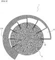
- FIG. 4 shows another example in which the nerve probe array 1 according to this embodiment is connected to the nerve N.
- FIG. 5 shows the nerve N to which the nerve probe array 1 is connected as shown in FIG. 4 , in a sectional direction.
- the connector 10 spirally surrounds the outer circumference of the nerve N and is connected to the nerve N.
- the plurality of probes 20 may be inserted into the nerve at different locations along the length direction of the nerve N. Therefore, the plurality of probes 20 do not pierce any one region intensively, thereby minimizing the damage of the nerve N.
- the connector 10 when the connector 10 spirally surrounds the outer circumference of the nerve N, the connector 10 may make at least one turn around the nerve N.
- the connector 10 does not perfectly bind the nerve N in a closed loop at any region.
- the plurality of probes 20 are arranged over the entire length of the connector 10, if the connector 10 makes at least one turn around the nerve N, as shown in FIG. 5 , the plurality of probes 20 may be disposed over the entire inside of the nerve N in a radial pattern.
- the nerve N includes a plurality of nerve bundles N1, N2 therein. Since the plurality of probes 20 are disposed over the entire inside of the nerve N in a spiral pattern, electrodes of high density (great number) may be regularly disposed in the nerve N. Therefore, electrodes may be located at substantially all nerve bundles. Accordingly, accurate nerve signals may be acquired, and nerve probing and stimulation location selectivity may be greatly enhanced.
- the connector 10 also surrounds the nerve in a state of erecting so that the side 11 forming its thickness comes into contact with the outer circumference of the nerve N. Therefore, the contact area with the outer circumference of the nerve N may be minimized.
- FIGS. 6A and 6B show that the nerve probe array 1 according to this embodiment is connected to the nerve N.
- a jig 2 made of a flexible material to connect the nerve probe array 1 is interposed at the periphery of the nerve N in advance.
- the jig 2 has a cylindrical body 3, and the body 3 has a thin slit 4 into which the connector 10 and the probe 20 may be inserted.
- the slit 4 is spirally formed along the length direction of the body 3 and is perfectly opened so that the outer circumference of the nerve N is exposed through the slit 4.
- a mark 5 may be formed near the slit 4 to exhibit a location where the probe 20 is to be inserted.
- An operator inserts the flexible connector 10 into the slot 4 to wind along the path of the slit 4, and simultaneously drives the probes 20 into the nerve N in order, along a winding direction, while checking a location where the mark 5 is formed.
- the jig 2 is released to be removed from the nerve N, and then the nerve probe array 1 is connected to the nerve N, as shown in FIG. 4 .
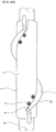
- FIG. 7 shows a nerve probe array 1' according to another embodiment of the present disclosure.
- the connector 10' has a linear shape. However, in order to wind the connector 10' around the nerve N in a spiral pattern, the connector 10' is formed to be shrinkable or expandable along its length direction.
- the connector 10' includes a plurality of fixing portions 110 to which the plurality of probes 20 may be respectively fixed, and a stretchable portion 120 for connecting two fixing portions 110 and formed length-adjustably.
- the fixing portion 110 has a thin plate shape and may be molded integrally with the body 210 of the probe 20.
- the probe 20 may be bent or curved as desired with respect to the fixing portion 110.
- the stretchable portion 120 is made of meander structures 121, 122 which are meanderingly bent to have flexibility and elasticity simultaneously.
- Two meander structures 121, 122 are formed in parallel to enhance a supporting force to the fixing portion 110 and structurally stabilize the connector 10'.
- the cable 214 extending from each probe 20 is elongated along the fixing portion 110 and extends to electronic equipment(not shown) such as wireless communication equipment through the stretchable portion 120.
- each probe 20 Four cables 214 extending from each probe 20 are elongated in parallel without overlapping with each other on the connector 10', till an end of the connector 10'.
- the stretchable portion 120 if all cables are accumulatively formed at the stretchable portion 120, the stretchable portion 120 inevitably has an increased width. Therefore, according to this embodiment, the cable 214 accumulated from the leftmost fixing portion 111 extends to the central fixing portion 112 along the stretchable portion 122 at a top side and then extends to the rightmost fixing portion 113, namely to one end of the connector 10', without adding a cable 214.
- the cable 214 extending from a probe 20 at a central location extends along the stretchable portion 121 at a bottom side to one end of the connector 10'.
- the connector 10' since the connector 10' has flexibility and elasticity simultaneously, the connector 10' of a linear shape may spirally surround the nerve N, and when being connected to the nerve N, a partial length of the connector 10' may be elongated to adjust locations of the probes 20. Therefore, the locations of the probes 20 may be adjusted as desired.
- FIG. 8 shows that the nerve probe array 1' according to this embodiment is connected to the nerve N.
- loops 130 may be formed at both ends of the connector 10', and a thread 131 may be put into the loops 130 and sewed to the nerve N so as to provide an additional supporting force to the nerve probe array 1' with respect to the nerve N.
- the connector 10' has a meander structure, but the present disclosure is not limited thereto.
- FIG. 9 shows a nerve probe array 1" according to another embodiment of the present disclosure.
- the nerve probe array 1" includes a connector 10" having a band shape.
- the connector 10" is elongated in a linear shape as a whole.
- the connector 10" may be flexibly bent and simultaneously stretchable in a length direction thereof.
- the connector 10" may be made of a silicon material such as PDMS, and various elastomer-type materials may also be used.
- a cable formed thereon may also be formed to be length-adjustable.
- the cable may be prepared by mixing conductive nano powder such as carbon nano tube (CNT) or grapheme with PDMS and curing the same, or forming/patterning a metal film on a rubber which has already been stretched to form a wrinkled film cable.
- a conductive liquid metal may be put into a fluid channel, which has already been formed in a flexible material, to implement the cable.
- nerve probe array 1" is substantially identical to those of the nerve probe array 1 of FIG. 1 and thus not described in detail here.
- FIG. 10 shows that the nerve probe array 1" according to this embodiment is connected to the nerve N.
- the connector 10" has a linear shape, and thus the connector 10" may spirally surround the outer circumference of the nerve N more easily in a state where a side of the connector 10" forming its width lies to contact the outer circumference of the nerve N.
- the probe 20 is bent as much as about 90 degrees with respect to the connector 10" and inserted into the nerve N.
- the nerve probe array 1" is not always connected to the nerve N in the above way, and it will be understood that the connector 10" may also be wound around the nerve N in a erecting state so that a side of the connector forming its thickness contacts the outer circumference of the nerve N, by using a tool similar to the jig 2 depicted in FIG. 6 (see FIG. 4 ).
Landscapes
- Health & Medical Sciences (AREA)
- Life Sciences & Earth Sciences (AREA)
- General Health & Medical Sciences (AREA)
- Veterinary Medicine (AREA)
- Engineering & Computer Science (AREA)
- Biomedical Technology (AREA)
- Animal Behavior & Ethology (AREA)
- Public Health (AREA)
- Heart & Thoracic Surgery (AREA)
- Neurology (AREA)
- Medical Informatics (AREA)
- Radiology & Medical Imaging (AREA)
- Biophysics (AREA)
- Molecular Biology (AREA)
- Physics & Mathematics (AREA)
- Pathology (AREA)
- Neurosurgery (AREA)
- Surgery (AREA)
- Nuclear Medicine, Radiotherapy & Molecular Imaging (AREA)
- Cardiology (AREA)
- Orthopedic Medicine & Surgery (AREA)
- Measurement And Recording Of Electrical Phenomena And Electrical Characteristics Of The Living Body (AREA)
- Electrotherapy Devices (AREA)
- Physiology (AREA)
Claims (13)
- Nervensonden-Array (1), umfassend:einen Verbinder (10) aus einem flexiblen Material; undeine Vielzahl von mit dem Verbinder (10) verbundenen Sonden (20), wobei jede Sonde (20) der Vielzahl von Sonden eine am Körper der Sonde ausgebildete Elektrode aufweist,wobei die Vielzahl von Sonden (20) in der Längsrichtung des Verbinders (10) in Abständen angeordnet ist, undwobei der Verbinder (10) einen Außenumfang eines Nerven (N) umgibt und die Vielzahl von Sonden (20) den Außenumfang des Nerven (N) durchsticht und in den Nerv (N) eingeführt ist, dadurch gekennzeichnet, dassjede Sonde (20) eine Hakenstruktur umfasst, so dass die Sonde (20) an der Innenseite des Nerven (N) eingehakt ist und nicht in die der Einführrichtung der Sonde (20) in den Nerv (N) entgegengesetzte Richtung gezogen wird,wobei die Hakenstruktur ein scharfer Vorsprung (212) ist, der derart an einer Seite der Sonde (20) ausgebildet ist, dass sich ein Ende des Vorsprungs (212) in die der Einführrichtung der Sonde (20) in den Nerv (N) entgegengesetzte Richtung erstreckt,wobei eine einzelne Sonde (20) eine Vielzahl von Vorsprüngen (212) umfasst,wobei die Vielzahl von Vorsprüngen (212) entlang der Längsrichtung der Sonde (20) an verschiedenen Stellen ausgebildet ist, undwobei die Vielzahl von Elektroden (213) so ausgebildet ist, dass sie die Vielzahl von Vorsprüngen (212) jeweils ummantelt.
- Nervensonden-Array (1) nach Anspruch 1,
wobei die Vielzahl von Sonden (20) eine Sonde mit einer von einer anderen Sonde abweichenden Länge umfasst. - Nervensonden-Array (1) nach Anspruch 2,
wobei mindestens eine Sonde (20) der Vielzahl von Sonden derart ausgebildet ist, dass sie in das Zentrum des Nerven (N) hineinreicht. - Nervensonden-Array (1) nach Anspruch 1,
wobei die in den Nerv (N) eingeführte Vielzahl von Sonden (20), wenn der Nerv (N) in einer zur Längsrichtung des Verbinders (10) senkrechten Querschnittrichtung betrachtet wird, radial angeordnet ist. - Nervensonden-Array (1) nach Anspruch 4,
wobei die Vielzahl von Sonden (20) in gleichmäßigen Abständen angeordnet ist. - Nervensonden-Array (1) nach Anspruch 1,
wobei der Verbinder (10) den Außenumfang des Nerven (N) derart umgibt, dass die Vielzahl von Sonden (20) entlang der Längsrichtung des Nerven (N) an verschiedenen Stellen in den Nerv (N) eingeführt ist. - Nervensonden-Array (1) nach Anspruch 6,
wobei der Verbinder (10) bogenförmig ist. - Nervensonden-Array (1) nach Anspruch 6,
wobei der Verbinder (10) geradlinig ist und entlang seiner Längsrichtung längenverstellbar ist. - Nervensonden-Array (1) nach Anspruch 8,
wobei der Verbinder (10) Folgendes umfasst:eine Vielzahl von Befestigungsabschnitten (110), an denen jeweils die Vielzahl von Sonden (20) befestigt ist; undeinen längenverstellbaren dehnbaren Abschnitt (120) zum Verbinden von zueinander benachbarten Befestigungsabschnitten (110). - Nervensonden-Array (1) nach Anspruch 6,
wobei die Vielzahl von Sonden (20) über die gesamte Länge des Verbinders (10) angeordnet ist, und
wobei der Verbinder (10) sich mindestens einmal um den Nerv (N) windet. - Nervensonden-Array (1) nach Anspruch 1,
wobei der Verbinder (10) eine dünne Plattenform aufweist, deren Breite größer als ihre Dicke ist, und
wobei der Verbinder (10) den Nerv (N) in einem aufgerichteten Zustand umgibt, derart dass eine die Dicke bildende Seite des Verbinders (10) an dem Außenumfang des Nerven (N) zur Anlage kommt. - Nervensonden-Array (1) nach Anspruch 1,
wobei eine Vielzahl von Elektroden (213) an einer einzelnen Sonde (20) ausgebildet ist, und
wobei die Vielzahl von Elektroden (213) entlang der Längsrichtung der Sonde (20) an verschiedenen Stellen ausgebildet ist. - Nervensonden-Array (1) nach Anspruch 1,
wobei die Vielzahl von Sonden (20) aus flexiblem Material ist oder an der Oberfläche mit einem flexiblen Material beschichtet ist.
Applications Claiming Priority (2)
| Application Number | Priority Date | Filing Date | Title |
|---|---|---|---|
| KR1020150105248A KR101700886B1 (ko) | 2015-07-24 | 2015-07-24 | 신경 손상을 최소화한 고성능 신경 탐침 구조체 |
| PCT/KR2016/008035 WO2017018738A1 (ko) | 2015-07-24 | 2016-07-22 | 신경 손상을 최소화한 고성능 신경 탐침 구조체 |
Publications (3)
| Publication Number | Publication Date |
|---|---|
| EP3326526A1 EP3326526A1 (de) | 2018-05-30 |
| EP3326526A4 EP3326526A4 (de) | 2019-03-20 |
| EP3326526B1 true EP3326526B1 (de) | 2020-07-22 |
Family
ID=57836401
Family Applications (1)
| Application Number | Title | Priority Date | Filing Date |
|---|---|---|---|
| EP16830771.8A Active EP3326526B1 (de) | 2015-07-24 | 2016-07-22 | Hochleistungsfähige nervensondierungsstruktur mit minimaler nervenschädigung |
Country Status (5)
| Country | Link |
|---|---|
| US (1) | US10206597B2 (de) |
| EP (1) | EP3326526B1 (de) |
| KR (1) | KR101700886B1 (de) |
| CN (1) | CN107835655B (de) |
| WO (1) | WO2017018738A1 (de) |
Families Citing this family (11)
| Publication number | Priority date | Publication date | Assignee | Title |
|---|---|---|---|---|
| KR101875511B1 (ko) | 2017-02-09 | 2018-08-09 | 한국과학기술연구원 | 신경 탐침 삽입 장치 |
| EP3600526A1 (de) * | 2017-03-22 | 2020-02-05 | Verily Life Sciences LLC | Befestigung einer anordnung neuronaler elektroden |
| CN107126290B (zh) * | 2017-04-26 | 2021-07-09 | 吴恩德 | 一种实验动物用人工视神经套管 |
| KR102021977B1 (ko) * | 2017-12-14 | 2019-09-17 | 한국기계연구원 | 말초 운동 신경신호 측정 시스템 및 이를 이용한 말초 운동 신경신호 판별 방법 |
| KR102380773B1 (ko) * | 2019-08-12 | 2022-04-04 | 단국대학교 천안캠퍼스 산학협력단 | 말초신경 신호 획득용 전극 |
| KR102325041B1 (ko) * | 2019-11-18 | 2021-11-11 | 재단법인대구경북과학기술원 | 신경전극 배열체 및 이의 제조방법 |
| KR102421981B1 (ko) * | 2020-06-03 | 2022-07-15 | 인제대학교 산학협력단 | 신경전도기구 및 이를 이용한 신경전도 시스템 |
| CN113180885A (zh) * | 2021-04-01 | 2021-07-30 | 重庆市畜牧科学院 | 一种视神经接口及其制备方法 |
| CN113521319B (zh) * | 2021-08-04 | 2022-09-16 | 上海交通大学 | 用于生物植入的柔性高密度多功能神经探针及制备方法 |
| CN113616211B (zh) * | 2021-08-30 | 2024-04-09 | 江西脑虎科技有限公司 | 一种柔性神经电极结构及其制备方法 |
| CN115054258B (zh) * | 2022-06-17 | 2024-11-12 | 上海阶梯医疗科技有限公司 | 一种用于周围神经的柔性电极及其制造方法 |
Family Cites Families (26)
| Publication number | Priority date | Publication date | Assignee | Title |
|---|---|---|---|---|
| US4590946A (en) * | 1984-06-14 | 1986-05-27 | Biomed Concepts, Inc. | Surgically implantable electrode for nerve bundles |
| US4573481A (en) * | 1984-06-25 | 1986-03-04 | Huntington Institute Of Applied Research | Implantable electrode array |
| US4920979A (en) * | 1988-10-12 | 1990-05-01 | Huntington Medical Research Institute | Bidirectional helical electrode for nerve stimulation |
| US4979511A (en) * | 1989-11-03 | 1990-12-25 | Cyberonics, Inc. | Strain relief tether for implantable electrode |
| US5400784A (en) * | 1993-10-15 | 1995-03-28 | Case Western Reserve University | Slowly penetrating inter-fascicular nerve cuff electrode and method of using |
| JP3963485B2 (ja) | 1997-04-11 | 2007-08-22 | アルザ コーポレイション | 最小限での侵入性の検出用装置 |
| US20040111139A1 (en) * | 2002-12-10 | 2004-06-10 | Mccreery Douglas B. | Apparatus and methods for differential stimulation of nerve fibers |
| EP1723983B1 (de) | 2005-05-20 | 2013-07-10 | Imec | Sonde für die elektrische Stimulation und Bestimmung der Aktivität von erregbaren Zellen |
| US20080027524A1 (en) * | 2006-07-26 | 2008-01-31 | Maschino Steven E | Multi-electrode assembly for an implantable medical device |
| JP5041584B2 (ja) * | 2007-02-01 | 2012-10-03 | 独立行政法人国立循環器病研究センター | 神経信号用プローバ、神経信号出力装置、神経信号記録装置、神経刺激装置及び神経信号入出力装置 |
| US8630711B1 (en) * | 2008-10-02 | 2014-01-14 | University Of Utah Research Foundation | Systems and methods for treating disorders by selectively activating and/or blocking muscles through intrafasicular stimulation of the pudendal nerve |
| US8639312B2 (en) * | 2008-12-10 | 2014-01-28 | University Of Utah Research Foundation | System and method for electrically shielding a microelectrode array in a physiological pathway from electrical noise |
| US20110288391A1 (en) * | 2010-05-19 | 2011-11-24 | Purdue Research Foundation | Titanium-Based Multi-Channel Microelectrode Array for Electrophysiological Recording and Stimulation of Neural Tissue |
| US8788045B2 (en) * | 2010-06-08 | 2014-07-22 | Bluewind Medical Ltd. | Tibial nerve stimulation |
| JP5684384B2 (ja) | 2010-07-19 | 2015-03-11 | カーディアック ペースメイカーズ, インコーポレイテッド | 迷走神経を刺激するためのシステム |
| KR101158775B1 (ko) * | 2010-11-16 | 2012-06-22 | 연세대학교 산학협력단 | 나노 와이어와 커프를 활용한 신경 소자 |
| KR101232278B1 (ko) | 2011-01-21 | 2013-02-12 | 한국과학기술연구원 | 손상된 신경의 기능을 복구하기 위한 신경 도관 및 이를 이용한 신경 신호 검출 장치 |
| WO2012170340A2 (en) | 2011-06-04 | 2012-12-13 | The Regents Of The University Of Michigan | Insertable neural probe with flexible structure |
| WO2013006295A1 (en) * | 2011-07-07 | 2013-01-10 | Cardiac Pacemakers, Inc. | Insulation and stability features for an implantable medical device lead |
| US20130144145A1 (en) * | 2011-12-05 | 2013-06-06 | University Of Southern California | Implantable neural tissue reporting probe and methods of manufacturing and implanting same |
| US9095267B2 (en) * | 2011-12-22 | 2015-08-04 | Modular Bionics Inc. | Neural interface device and insertion tools |
| KR101327762B1 (ko) | 2012-01-27 | 2013-11-11 | 연세대학교 산학협력단 | 나노 와이어와 지지층을 포함하는 신경소자 |
| KR20140133202A (ko) * | 2013-05-10 | 2014-11-19 | 한국과학기술연구원 | 손상된 신경 재생을 위한 생체 신호 기반 전기 자극 시스템 |
| GB2528070B (en) * | 2014-07-08 | 2016-12-14 | Vagonyx Ltd | Nerve stimulating and monitoring device |
| US20160331326A1 (en) * | 2015-02-13 | 2016-11-17 | National University Of Singapore | Flexible neural strip electrodes, flexible neural ribbon electrodes and compartment based embedded nerve tissue electrode interfaces for peripheral nerves |
| US20160235329A1 (en) * | 2015-02-13 | 2016-08-18 | The Charles Stark Draper Laboratory, Inc. | Nerve bundle cuff including electrodes and transducers |
-
2015
- 2015-07-24 KR KR1020150105248A patent/KR101700886B1/ko not_active Expired - Fee Related
-
2016
- 2016-03-22 US US15/077,172 patent/US10206597B2/en active Active
- 2016-07-22 CN CN201680041169.9A patent/CN107835655B/zh active Active
- 2016-07-22 EP EP16830771.8A patent/EP3326526B1/de active Active
- 2016-07-22 WO PCT/KR2016/008035 patent/WO2017018738A1/ko not_active Ceased
Non-Patent Citations (1)
| Title |
|---|
| None * |
Also Published As
| Publication number | Publication date |
|---|---|
| US20170020403A1 (en) | 2017-01-26 |
| CN107835655B (zh) | 2021-08-10 |
| CN107835655A (zh) | 2018-03-23 |
| WO2017018738A1 (ko) | 2017-02-02 |
| KR101700886B1 (ko) | 2017-02-01 |
| EP3326526A1 (de) | 2018-05-30 |
| EP3326526A4 (de) | 2019-03-20 |
| US10206597B2 (en) | 2019-02-19 |
Similar Documents
| Publication | Publication Date | Title |
|---|---|---|
| EP3326526A1 (de) | Hochleistungsfähige nervensondierungsstruktur mit minimaler nervenschädigung | |
| US8170638B2 (en) | MEMS flexible substrate neural probe and method of fabricating same | |
| US11219379B2 (en) | Wireless MEMS left atrial pressure sensor | |
| RU2746456C1 (ru) | Электрод для нейромодуляции в сборе | |
| RU2687604C2 (ru) | Катетер со множеством несущих различной длины, расположенных на одном или более дистальных сегментах | |
| US4850359A (en) | Electrical brain-contact devices | |
| US4903702A (en) | Brain-contact for sensing epileptogenic foci with improved accuracy | |
| EP2552536B1 (de) | Vorrichtung zur interaktion mit nervengewebe | |
| CN107041744B (zh) | 具有紧密间隔的微型双极电极的导管脊组件 | |
| US8849415B2 (en) | Multi-channel connector for brain stimulation system | |
| US6597953B2 (en) | Furcated sensing and stimulation lead | |
| US8543222B1 (en) | Implantable lead and accessories | |
| US11602630B2 (en) | Systems and methods for flexible electrode arrays | |
| CN114788700A (zh) | 一种带有辅助结构的神经接口 | |
| JP2014500105A (ja) | 電気刺激システムのための半径方向を整列させたセグメント電極を有するリードを製造するための方法 | |
| JP6576367B2 (ja) | 神経刺激電極 | |
| US20180353750A1 (en) | Systems and Methods for Ruggedized Penetrating Medical Electrode Arrays | |
| US20130338466A1 (en) | Nerve surveillance electrode assembly | |
| US20100240240A1 (en) | Flexible connector for implantable electrical stimulation lead | |
| JP4251898B2 (ja) | 穿刺センサを有するカテーテル | |
| US11458305B2 (en) | Device for inserting neural probes | |
| Pothof et al. | Fabrication and characterization of a high-resolution neural probe for stereoelectroencephalography and single neuron recording | |
| US11389645B2 (en) | Chronic implantable neural probe array for neural signal acquisition and stimulation | |
| US3089483A (en) | Multiple electrode holders for indicating nerve responses to stimulation | |
| EP3558453B1 (de) | Elektrodenanordnung zur oberflächen- und intragewebeaufzeichnung und -stimulation |
Legal Events
| Date | Code | Title | Description |
|---|---|---|---|
| STAA | Information on the status of an ep patent application or granted ep patent |
Free format text: STATUS: THE INTERNATIONAL PUBLICATION HAS BEEN MADE |
|
| PUAI | Public reference made under article 153(3) epc to a published international application that has entered the european phase |
Free format text: ORIGINAL CODE: 0009012 |
|
| STAA | Information on the status of an ep patent application or granted ep patent |
Free format text: STATUS: REQUEST FOR EXAMINATION WAS MADE |
|
| 17P | Request for examination filed |
Effective date: 20180109 |
|
| AK | Designated contracting states |
Kind code of ref document: A1 Designated state(s): AL AT BE BG CH CY CZ DE DK EE ES FI FR GB GR HR HU IE IS IT LI LT LU LV MC MK MT NL NO PL PT RO RS SE SI SK SM TR |
|
| AX | Request for extension of the european patent |
Extension state: BA ME |
|
| DAV | Request for validation of the european patent (deleted) | ||
| DAX | Request for extension of the european patent (deleted) | ||
| A4 | Supplementary search report drawn up and despatched |
Effective date: 20190214 |
|
| RIC1 | Information provided on ipc code assigned before grant |
Ipc: A61B 5/0478 20060101ALI20190208BHEP Ipc: A61B 5/00 20060101ALI20190208BHEP Ipc: A61B 5/04 20060101AFI20190208BHEP Ipc: A61N 1/05 20060101ALI20190208BHEP Ipc: A61N 1/04 20060101ALI20190208BHEP |
|
| GRAP | Despatch of communication of intention to grant a patent |
Free format text: ORIGINAL CODE: EPIDOSNIGR1 |
|
| STAA | Information on the status of an ep patent application or granted ep patent |
Free format text: STATUS: GRANT OF PATENT IS INTENDED |
|
| RIC1 | Information provided on ipc code assigned before grant |
Ipc: A61B 5/00 20060101ALI20200127BHEP Ipc: A61B 5/04 20060101AFI20200127BHEP Ipc: A61B 5/0478 20060101ALI20200127BHEP Ipc: A61N 1/05 20060101ALI20200127BHEP Ipc: A61N 1/04 20060101ALI20200127BHEP |
|
| INTG | Intention to grant announced |
Effective date: 20200221 |
|
| GRAS | Grant fee paid |
Free format text: ORIGINAL CODE: EPIDOSNIGR3 |
|
| GRAA | (expected) grant |
Free format text: ORIGINAL CODE: 0009210 |
|
| STAA | Information on the status of an ep patent application or granted ep patent |
Free format text: STATUS: THE PATENT HAS BEEN GRANTED |
|
| AK | Designated contracting states |
Kind code of ref document: B1 Designated state(s): AL AT BE BG CH CY CZ DE DK EE ES FI FR GB GR HR HU IE IS IT LI LT LU LV MC MK MT NL NO PL PT RO RS SE SI SK SM TR |
|
| REG | Reference to a national code |
Ref country code: GB Ref legal event code: FG4D |
|
| REG | Reference to a national code |
Ref country code: CH Ref legal event code: EP |
|
| REG | Reference to a national code |
Ref country code: DE Ref legal event code: R096 Ref document number: 602016040548 Country of ref document: DE |
|
| REG | Reference to a national code |
Ref country code: AT Ref legal event code: REF Ref document number: 1292590 Country of ref document: AT Kind code of ref document: T Effective date: 20200815 |
|
| REG | Reference to a national code |
Ref country code: IE Ref legal event code: FG4D |
|
| REG | Reference to a national code |
Ref country code: DE Ref legal event code: R079 Ref document number: 602016040548 Country of ref document: DE Free format text: PREVIOUS MAIN CLASS: A61B0005040000 Ipc: A61B0005240000 |
|
| REG | Reference to a national code |
Ref country code: LT Ref legal event code: MG4D |
|
| REG | Reference to a national code |
Ref country code: AT Ref legal event code: MK05 Ref document number: 1292590 Country of ref document: AT Kind code of ref document: T Effective date: 20200722 |
|
| PG25 | Lapsed in a contracting state [announced via postgrant information from national office to epo] |
Ref country code: ES Free format text: LAPSE BECAUSE OF FAILURE TO SUBMIT A TRANSLATION OF THE DESCRIPTION OR TO PAY THE FEE WITHIN THE PRESCRIBED TIME-LIMIT Effective date: 20200722 Ref country code: BG Free format text: LAPSE BECAUSE OF FAILURE TO SUBMIT A TRANSLATION OF THE DESCRIPTION OR TO PAY THE FEE WITHIN THE PRESCRIBED TIME-LIMIT Effective date: 20201022 Ref country code: PT Free format text: LAPSE BECAUSE OF FAILURE TO SUBMIT A TRANSLATION OF THE DESCRIPTION OR TO PAY THE FEE WITHIN THE PRESCRIBED TIME-LIMIT Effective date: 20201123 Ref country code: HR Free format text: LAPSE BECAUSE OF FAILURE TO SUBMIT A TRANSLATION OF THE DESCRIPTION OR TO PAY THE FEE WITHIN THE PRESCRIBED TIME-LIMIT Effective date: 20200722 Ref country code: LT Free format text: LAPSE BECAUSE OF FAILURE TO SUBMIT A TRANSLATION OF THE DESCRIPTION OR TO PAY THE FEE WITHIN THE PRESCRIBED TIME-LIMIT Effective date: 20200722 Ref country code: AT Free format text: LAPSE BECAUSE OF FAILURE TO SUBMIT A TRANSLATION OF THE DESCRIPTION OR TO PAY THE FEE WITHIN THE PRESCRIBED TIME-LIMIT Effective date: 20200722 Ref country code: NO Free format text: LAPSE BECAUSE OF FAILURE TO SUBMIT A TRANSLATION OF THE DESCRIPTION OR TO PAY THE FEE WITHIN THE PRESCRIBED TIME-LIMIT Effective date: 20201022 Ref country code: GR Free format text: LAPSE BECAUSE OF FAILURE TO SUBMIT A TRANSLATION OF THE DESCRIPTION OR TO PAY THE FEE WITHIN THE PRESCRIBED TIME-LIMIT Effective date: 20201023 Ref country code: FI Free format text: LAPSE BECAUSE OF FAILURE TO SUBMIT A TRANSLATION OF THE DESCRIPTION OR TO PAY THE FEE WITHIN THE PRESCRIBED TIME-LIMIT Effective date: 20200722 Ref country code: SE Free format text: LAPSE BECAUSE OF FAILURE TO SUBMIT A TRANSLATION OF THE DESCRIPTION OR TO PAY THE FEE WITHIN THE PRESCRIBED TIME-LIMIT Effective date: 20200722 |
|
| PG25 | Lapsed in a contracting state [announced via postgrant information from national office to epo] |
Ref country code: RS Free format text: LAPSE BECAUSE OF FAILURE TO SUBMIT A TRANSLATION OF THE DESCRIPTION OR TO PAY THE FEE WITHIN THE PRESCRIBED TIME-LIMIT Effective date: 20200722 Ref country code: PL Free format text: LAPSE BECAUSE OF FAILURE TO SUBMIT A TRANSLATION OF THE DESCRIPTION OR TO PAY THE FEE WITHIN THE PRESCRIBED TIME-LIMIT Effective date: 20200722 Ref country code: LV Free format text: LAPSE BECAUSE OF FAILURE TO SUBMIT A TRANSLATION OF THE DESCRIPTION OR TO PAY THE FEE WITHIN THE PRESCRIBED TIME-LIMIT Effective date: 20200722 Ref country code: IS Free format text: LAPSE BECAUSE OF FAILURE TO SUBMIT A TRANSLATION OF THE DESCRIPTION OR TO PAY THE FEE WITHIN THE PRESCRIBED TIME-LIMIT Effective date: 20201122 |
|
| REG | Reference to a national code |
Ref country code: CH Ref legal event code: PL |
|
| PG25 | Lapsed in a contracting state [announced via postgrant information from national office to epo] |
Ref country code: NL Free format text: LAPSE BECAUSE OF FAILURE TO SUBMIT A TRANSLATION OF THE DESCRIPTION OR TO PAY THE FEE WITHIN THE PRESCRIBED TIME-LIMIT Effective date: 20200722 |
|
| REG | Reference to a national code |
Ref country code: DE Ref legal event code: R097 Ref document number: 602016040548 Country of ref document: DE |
|
| REG | Reference to a national code |
Ref country code: BE Ref legal event code: MM Effective date: 20200731 |
|
| PG25 | Lapsed in a contracting state [announced via postgrant information from national office to epo] |
Ref country code: CZ Free format text: LAPSE BECAUSE OF FAILURE TO SUBMIT A TRANSLATION OF THE DESCRIPTION OR TO PAY THE FEE WITHIN THE PRESCRIBED TIME-LIMIT Effective date: 20200722 Ref country code: DK Free format text: LAPSE BECAUSE OF FAILURE TO SUBMIT A TRANSLATION OF THE DESCRIPTION OR TO PAY THE FEE WITHIN THE PRESCRIBED TIME-LIMIT Effective date: 20200722 Ref country code: CH Free format text: LAPSE BECAUSE OF NON-PAYMENT OF DUE FEES Effective date: 20200731 Ref country code: RO Free format text: LAPSE BECAUSE OF FAILURE TO SUBMIT A TRANSLATION OF THE DESCRIPTION OR TO PAY THE FEE WITHIN THE PRESCRIBED TIME-LIMIT Effective date: 20200722 Ref country code: LI Free format text: LAPSE BECAUSE OF NON-PAYMENT OF DUE FEES Effective date: 20200731 Ref country code: LU Free format text: LAPSE BECAUSE OF NON-PAYMENT OF DUE FEES Effective date: 20200722 Ref country code: EE Free format text: LAPSE BECAUSE OF FAILURE TO SUBMIT A TRANSLATION OF THE DESCRIPTION OR TO PAY THE FEE WITHIN THE PRESCRIBED TIME-LIMIT Effective date: 20200722 Ref country code: IT Free format text: LAPSE BECAUSE OF FAILURE TO SUBMIT A TRANSLATION OF THE DESCRIPTION OR TO PAY THE FEE WITHIN THE PRESCRIBED TIME-LIMIT Effective date: 20200722 Ref country code: SM Free format text: LAPSE BECAUSE OF FAILURE TO SUBMIT A TRANSLATION OF THE DESCRIPTION OR TO PAY THE FEE WITHIN THE PRESCRIBED TIME-LIMIT Effective date: 20200722 |
|
| PLBE | No opposition filed within time limit |
Free format text: ORIGINAL CODE: 0009261 |
|
| STAA | Information on the status of an ep patent application or granted ep patent |
Free format text: STATUS: NO OPPOSITION FILED WITHIN TIME LIMIT |
|
| PG25 | Lapsed in a contracting state [announced via postgrant information from national office to epo] |
Ref country code: AL Free format text: LAPSE BECAUSE OF FAILURE TO SUBMIT A TRANSLATION OF THE DESCRIPTION OR TO PAY THE FEE WITHIN THE PRESCRIBED TIME-LIMIT Effective date: 20200722 Ref country code: BE Free format text: LAPSE BECAUSE OF NON-PAYMENT OF DUE FEES Effective date: 20200731 |
|
| 26N | No opposition filed |
Effective date: 20210423 |
|
| PG25 | Lapsed in a contracting state [announced via postgrant information from national office to epo] |
Ref country code: SK Free format text: LAPSE BECAUSE OF FAILURE TO SUBMIT A TRANSLATION OF THE DESCRIPTION OR TO PAY THE FEE WITHIN THE PRESCRIBED TIME-LIMIT Effective date: 20200722 |
|
| PG25 | Lapsed in a contracting state [announced via postgrant information from national office to epo] |
Ref country code: IE Free format text: LAPSE BECAUSE OF NON-PAYMENT OF DUE FEES Effective date: 20200722 Ref country code: SI Free format text: LAPSE BECAUSE OF FAILURE TO SUBMIT A TRANSLATION OF THE DESCRIPTION OR TO PAY THE FEE WITHIN THE PRESCRIBED TIME-LIMIT Effective date: 20200722 |
|
| REG | Reference to a national code |
Ref country code: NL Ref legal event code: MP Effective date: 20200722 |
|
| PG25 | Lapsed in a contracting state [announced via postgrant information from national office to epo] |
Ref country code: TR Free format text: LAPSE BECAUSE OF FAILURE TO SUBMIT A TRANSLATION OF THE DESCRIPTION OR TO PAY THE FEE WITHIN THE PRESCRIBED TIME-LIMIT Effective date: 20200722 Ref country code: MT Free format text: LAPSE BECAUSE OF FAILURE TO SUBMIT A TRANSLATION OF THE DESCRIPTION OR TO PAY THE FEE WITHIN THE PRESCRIBED TIME-LIMIT Effective date: 20200722 Ref country code: CY Free format text: LAPSE BECAUSE OF FAILURE TO SUBMIT A TRANSLATION OF THE DESCRIPTION OR TO PAY THE FEE WITHIN THE PRESCRIBED TIME-LIMIT Effective date: 20200722 |
|
| PG25 | Lapsed in a contracting state [announced via postgrant information from national office to epo] |
Ref country code: MK Free format text: LAPSE BECAUSE OF FAILURE TO SUBMIT A TRANSLATION OF THE DESCRIPTION OR TO PAY THE FEE WITHIN THE PRESCRIBED TIME-LIMIT Effective date: 20200722 Ref country code: MC Free format text: LAPSE BECAUSE OF FAILURE TO SUBMIT A TRANSLATION OF THE DESCRIPTION OR TO PAY THE FEE WITHIN THE PRESCRIBED TIME-LIMIT Effective date: 20200722 |
|
| PGFP | Annual fee paid to national office [announced via postgrant information from national office to epo] |
Ref country code: GB Payment date: 20240620 Year of fee payment: 9 |
|
| PGFP | Annual fee paid to national office [announced via postgrant information from national office to epo] |
Ref country code: FR Payment date: 20240624 Year of fee payment: 9 |
|
| PGFP | Annual fee paid to national office [announced via postgrant information from national office to epo] |
Ref country code: DE Payment date: 20240620 Year of fee payment: 9 |
|
| REG | Reference to a national code |
Ref country code: DE Ref legal event code: R119 Ref document number: 602016040548 Country of ref document: DE |
|
| GBPC | Gb: european patent ceased through non-payment of renewal fee |
Effective date: 20250722 |
|
| PG25 | Lapsed in a contracting state [announced via postgrant information from national office to epo] |
Ref country code: GB Free format text: LAPSE BECAUSE OF NON-PAYMENT OF DUE FEES Effective date: 20250722 |
|
| PG25 | Lapsed in a contracting state [announced via postgrant information from national office to epo] |
Ref country code: DE Free format text: LAPSE BECAUSE OF NON-PAYMENT OF DUE FEES Effective date: 20260203 |
|
| PG25 | Lapsed in a contracting state [announced via postgrant information from national office to epo] |
Ref country code: FR Free format text: LAPSE BECAUSE OF NON-PAYMENT OF DUE FEES Effective date: 20250731 |