EP3326490B1 - Eine anordnung zum bewegen eines lagerraums in einem möbel - Google Patents
Eine anordnung zum bewegen eines lagerraums in einem möbel Download PDFInfo
- Publication number
- EP3326490B1 EP3326490B1 EP17396004.8A EP17396004A EP3326490B1 EP 3326490 B1 EP3326490 B1 EP 3326490B1 EP 17396004 A EP17396004 A EP 17396004A EP 3326490 B1 EP3326490 B1 EP 3326490B1
- Authority
- EP
- European Patent Office
- Prior art keywords
- cabinet
- bracket
- moving
- rack
- storage space
- Prior art date
- Legal status (The legal status is an assumption and is not a legal conclusion. Google has not performed a legal analysis and makes no representation as to the accuracy of the status listed.)
- Active
Links
- 230000007246 mechanism Effects 0.000 claims description 13
- 230000001174 ascending effect Effects 0.000 claims 1
- 239000002699 waste material Substances 0.000 description 11
- 230000000694 effects Effects 0.000 description 2
- 239000010806 kitchen waste Substances 0.000 description 1
- 230000003319 supportive effect Effects 0.000 description 1
Images

Classifications
-
- A—HUMAN NECESSITIES
- A47—FURNITURE; DOMESTIC ARTICLES OR APPLIANCES; COFFEE MILLS; SPICE MILLS; SUCTION CLEANERS IN GENERAL
- A47B—TABLES; DESKS; OFFICE FURNITURE; CABINETS; DRAWERS; GENERAL DETAILS OF FURNITURE
- A47B77/00—Kitchen cabinets
- A47B77/04—Provision for particular uses of compartments or other parts ; Compartments moving up and down, revolving parts
- A47B77/10—Provision for particular uses of compartments or other parts ; Compartments moving up and down, revolving parts with members movable outwards to a position of use, e.g. tables, ironing boards
-
- A—HUMAN NECESSITIES
- A47—FURNITURE; DOMESTIC ARTICLES OR APPLIANCES; COFFEE MILLS; SPICE MILLS; SUCTION CLEANERS IN GENERAL
- A47B—TABLES; DESKS; OFFICE FURNITURE; CABINETS; DRAWERS; GENERAL DETAILS OF FURNITURE
- A47B46/00—Cabinets, racks or shelf units, having one or more surfaces adapted to be brought into position for use by extending or pivoting
- A47B46/005—Cabinets, racks or shelf units, having one or more surfaces adapted to be brought into position for use by extending or pivoting by displacement in a vertical plane; by rotating about a horizontal axis
-
- B—PERFORMING OPERATIONS; TRANSPORTING
- B65—CONVEYING; PACKING; STORING; HANDLING THIN OR FILAMENTARY MATERIAL
- B65F—GATHERING OR REMOVAL OF DOMESTIC OR LIKE REFUSE
- B65F1/00—Refuse receptacles; Accessories therefor
- B65F1/14—Other constructional features; Accessories
- B65F1/1426—Housings, cabinets or enclosures for refuse receptacles
- B65F1/1436—Housings, cabinets or enclosures for refuse receptacles having a waste receptacle withdrawn upon opening of the enclosure
-
- A—HUMAN NECESSITIES
- A47—FURNITURE; DOMESTIC ARTICLES OR APPLIANCES; COFFEE MILLS; SPICE MILLS; SUCTION CLEANERS IN GENERAL
- A47B—TABLES; DESKS; OFFICE FURNITURE; CABINETS; DRAWERS; GENERAL DETAILS OF FURNITURE
- A47B88/00—Drawers for tables, cabinets or like furniture; Guides for drawers
- A47B88/90—Constructional details of drawers
- A47B2088/901—Drawers having a lifting mechanism
-
- A—HUMAN NECESSITIES
- A47—FURNITURE; DOMESTIC ARTICLES OR APPLIANCES; COFFEE MILLS; SPICE MILLS; SUCTION CLEANERS IN GENERAL
- A47B—TABLES; DESKS; OFFICE FURNITURE; CABINETS; DRAWERS; GENERAL DETAILS OF FURNITURE
- A47B88/00—Drawers for tables, cabinets or like furniture; Guides for drawers
- A47B88/40—Sliding drawers; Slides or guides therefor
- A47B88/453—Actuated drawers
- A47B88/457—Actuated drawers operated by electrically-powered actuation means
Definitions
- the invention relates to an arrangement for moving a storage space, a bracket or a waste-bag rack located in a cabinet, whereby, when opening a door or a drawer of the cabinet, it is possible by means of a mechanism related to the opening to implement the transfer of said storage space, bracket or rack fitted inside the cabinet and arranged to move in there out of the cabinet to reveal them.
- an extension plate which in the rest position, is concealed beneath the work top covering of a cupboard. It runs on lateral extension rails set in the base cupboard to run on inclined rails the leading edge of the extension plate lies in the extended position level with the work top. To ensure a level extension plate in the use position a lift is provided on the extension rails to raise the trailing edge of the extension plate to the level of the worktop.
- the extension plate is telescopic whilst the lift can be a lever which is connected beneath the extension plate where it is under the effect of a tensile spring.
- a refrigerator which includes a cabinet within which is arranged an upper fresh food compartment and a lower freezer compartment.
- a freezer basket is slidably supported in the freezer compartment, preferably for concurrent movement with a freezer door.
- the freezer basket is coupled to a lifting mechanism that selectively shifts the freezer basket from a first or lowered position to a second or raised position in order to facilitate removal of items from the freezer basket.
- the lifting mechanism can be formed by a mechanical, electrical or pneumatic system.
- an apparatus includes a container member slidably mounted between spaced parallel container support side walls, wherein the container support side walls are mounted within a cabinet housing.
- the container support includes a gear rack mounted from the container support to a rear wall of the container member, and further includes a lid control cable extending from the container member to the lid directed through cooperative pulleys to effect simultaneous opening of the lid upon projection of the container member exteriorly of the cabinet housing relative to the spaced container support side wall.
- a disadvantage of the arrangement described in US patent 7794027 is arranging, first, the motion of the base and the storage-bin bracket outwards and then, separately, the motion of the storage-bin bracket upwards.
- the storage bin When the storage bin is transferred back to the cabinet, it must be first pressed down to its base and the storage bin and its base must be then pushed into the cabinet.
- a disadvantage of other known arrangements described above is that the shelf comes out on the same level as it is in the cabinet. Thus in these, only the topmost outcoming shelf is well on view. The other shelves are left below the topmost shelf and in the dark.
- kitchen fittings include a sink which takes a space below at its point in the cabinet.
- the sink prevents the use of the top part of the cabinet.
- a waste bin set or a waste-bag rack for sorting, whereby it is naturally located in the bottom part of the cabinet.
- a waste-bag rack being on a lower level than normal is awkward to use, it being either behind a door to be opened or inside a drawer to be pulled out.
- the present invention provides a substantial improvement to prior art. This improvement is achieved when e.g. a storage space, a bracket or a bag rack intended to be a waste station or some other storage space in a cabinet is arranged movable. It is characteristic of the invention what is claimed in the independent claims 1 and 2.
- An advantage of the invention is that, in addition to conventional shelf spaces, a shelf or drawer space or equivalent at the point of the sink can be made more accessible when it also transfers e.g. by pulling the front edge of the drawer outwards and, more importantly, upwards.
- the size of the kitchen waste station is precisely such that it fits below the sink.
- it has been realised that it is easily transferrable by means of mechanisms outwards and upwards from there by supplying a motion for it from the front edge of the drawer. Also, storage spaces in other parts of the cabinet can be pulled out and better revealed in the way of the invention.
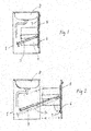
- Fig. 1 schematically shows an arrangement according to the present invention in a kitchen cabinet 1 at the point of a sink 2.
- a telescopic slide rail 3 To the frame of the cabinet 1 is fixedly fastened a telescopic slide rail 3.
- the out-coming end of the slide rail 3 is again fastened to a waste rack 4.
- the waste rack 4 is further fastened slidably to an out-pullable front wall 5, 6.
- slide rails 7 fastened inside the front wall 5, 6.
- the slide rail 3 guides the waste rack 4 to lift, as shown in Fig. 2 , at the same time as the waste rack 4 transfers outwards.
- the telescopic slide rail 3 is fixedly fast in the cabinet wall and keeps its direction.
- Fig. 2 shows that the drawer front wall 5, 6 keeps its height position when pulled outwards, but the waste rack 4 lifts and becomes well revealed and accessible.
- this arrangement requires e.g. in connection with the out-pulling a relieving spring, such as a gas spring 16, which is shown in Fig. 2 beside the slide rail 3.
- the relieving spring can also be installed as fastened on the wall 5, 6 beside the slide rail 7 in the vertical direction, whereby its relieving force is conveyed from downwards to the waste rack 4 or the utmost end of the slide rail 3.
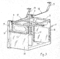
- Fig. 3 shows another version which shows as an example the transfer of a waste-bag rack 9 outwards and upwards as the front wall (not in the figure) is being pulled upwards.
- Fig. 3 shows the waste-bag rack 9 moving according to the invention and its also moving bracket part comprising side parts 15 and slide rails 10 directed upwards from it supported by which rails the waste-bag rack 9 moves up and down.
- the bracket part only moves horizontally out of the cabinet 1 and into the cabinet. It makes this motion supported by rotated profiles 17 of the top edges of the side parts 15. These profiles have supportive counter shapes on the interior walls (not shown in the figure) of the cabinet.
- This arrangement is also intended to be located at the point of the sink and the waste-bag rack 9 is positioned below the sink when it is totally inside the cabinet.
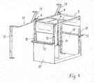
- Fig. 4 shows how the waste-bag rack 9 has moved with its bracket parts outwards from the cabinet and, at the same time, the waste-bag rack 9 has lifted upwards supported by the slide rails 10 and lifted by the gas spring 14.
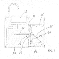
- Figs. 5-7 show the lifting of a storage-bin bracket 25 implemented by means of a mechanism combination to the top position at the same time as a moving bottom part 24 of the storage-bin bracket 25 transfers out along with a cabinet front wall 26.
- a first toothed bar 18 is fastened on the inner surface of the cabinet wall.
- a second toothed bar 19 is connected to the storage-bin bracket 25.
- cog wheels 20 and 21 Between the toothed bars 18 and 19 on a common axis 22 are arranged cog wheels 20 and 21 which, when being in contact with their corresponding toothed bars 18, 19, convey from the horizontal motion of the bottom part 24 of the storage-bin bracket 25 the vertical motion to the storage-bin bracket 25.
- a gas spring 27 which relieves the opening of the cabinet door and, at the same time, the lifting of all of the mass being lifted upwards.
- the transfer of the interior part of the cabinet outwards and upwards according to the invention can also be used in other parts of the cabinet than at the point of the sink.
- the moving interior part of the cabinet can be a part of a drawer or a space behind the cabinet door.
Landscapes
- Engineering & Computer Science (AREA)
- Mechanical Engineering (AREA)
- Drawers Of Furniture (AREA)
- Combinations Of Kitchen Furniture (AREA)
Claims (6)
- Anordnung zum Bewegen eines im Schrank (1) liegenden Güterraums, der ein von einem Träger (10, 15, 17) abgestütztes Gerüst (9) aufweist, wobei beim Öffnen der Tür des mit dem Träger im Eingriff gesetzten Schrankes (1) sind der Träger (10, 15, 17) und das Gerüst (9) zum Bewegen aus dem Schrank (1) heraus angeordnet sind, um den Güterraum (1) herauszubringen, wobei mit Hilfe der mit dem Schrank (1) verbundenen Steuerflächen (12, 13) eine Bewegungsbahn zum Bewegen des vorgenannten Gerüstes (4,9) angeordnet ist und durch Öffnen der Tür des Schrankes (1) die Bewegung des vorgenannten Gerüstes (9) mittels dieser Steuerflächen (12, 13) nach außen und nach oben geführt wird, wobei der Träger (10, 15, 17) Flankenteile (15) und nach oben gerichtete Gleitschienen (10) verbunden mit den vorgenannten Flankenteilen (15) zum Bewegen des Gerüstes (9) abgestützt von den vorgenannten Gleitschienen (10) nach oben und nach unten aufweist, wenn sich der Träger (10, 15, 17) abgestützt von den Randteilen der Profile (17) der Flankenteile (16) nach außen oder nach innen bewegt, wobei die vorgenannten Profile (17) von den an den Innenwänden des Schrankes befindlichen Gegenformen abgestützt sind.
- Anordnung zum Bewegen eines im Schrank (1) liegenden Güterraums, wobei der Güterraum den im Schrank liegenden Träger (25) aufweist, wobei beim Öffnen der mit dem Träger verbundenen Vorderwand 26 des Schrankes (1) der vorgenannte Träger (25) angeordnet ist mittels einer mechanischen Kombination sich aus dem Schrank bewegen, um den Güterraum herauszubringen, wobei an dem vorgenannten Träger eine mittels einer mechanischen Kombination eine Bewegungsbahn zum Bewegen des vorgenannten Trägers angeordnet ist, die beim Öffnen der Vorderwand (26) des Schrankes (1) den vorgenannten Träger (25) nach außen und nach oben führt, dadurch gekennzeichnet, dass mittels der vorgenannten mechanischen Kombination die Bewegung des Trägers (25) nach oben in die obere Position gleichzeitig mit dem Öffnen der Vorderwand (26) des Schrankes durchgeführt ist, wobei die erste Zahnstange (18) an der Innenfläche des Schrankes und die zweite Zahnstange (19) am Träger (25) mittels der sich auf den Bodenteil (24) stützenden Gleitschienen (28) befestigt ist, wobei der Bodenteil (24) mit der Vorderwand (26) verbunden ist, um für den vorgenannten Träger die Bewegung nach oben in senkrechter Richtung durchzuführen, wobei an der gemeinsamen Achse (22) zwischen den Zahnstangen (18, 19) im Eingriff mit jener entsprechenden Zahnstange (18, 19) Zahnräder (20, 21) angeordnet sind, was das Öffnen der Vorderwand (26) und die horizontale Bewegung des Bodenteils (24) nach außen für den Träger (25) zur seiner senkrechten Bewegung verwirklicht.
- Anordnung nach dem Anspruch 1, dadurch gekennzeichnet, dass die Bewegungsbahn rollen (8) oder Gleitstücke aufweist, die sich im Kontakt mit den steuernden Flächen (12, 13) bewegen und an dem vorgenannten Gerüst (9) befestigt sind.
- Anordnung nach dem Anspruch 1, dadurch gekennzeichnet, dass eine Gasdruckfeder (14) oder eine Ausgleichsgewichtsregelung angeordnet ist, um die Bewegung der vorgenannten Vorrichtung nach außen und/oder nach oben zu entlasten.
- Anordnung nach dem Anspruch 2, dadurch gekennzeichnet, dass eine Gasdruckfeder (27) zum Entlasten der Bewegung vorgenannten Vorrichtung nach außen und/oder nach oben angeordnet ist.
- Anordnung nach dem Anspruch 1 oder 2, dadurch gekennzeichnet, dass die Bewegungsbahn linear ist oder lineare oder gebogene Steigabschnitte unterschiedlichen Grades aufweist.
Priority Applications (1)
| Application Number | Priority Date | Filing Date | Title |
|---|---|---|---|
| PL17396004T PL3326490T3 (pl) | 2016-11-25 | 2017-11-24 | Układ do przemieszczania przestrzeni przechowalniczej w szafce |
Applications Claiming Priority (1)
| Application Number | Priority Date | Filing Date | Title |
|---|---|---|---|
| FIU20160187U FI11506U1 (fi) | 2016-11-25 | 2016-11-25 | Sovitelma kaapistossa sijaitsevan tavaratilan liikuttamiseksi |
Publications (2)
| Publication Number | Publication Date |
|---|---|
| EP3326490A1 EP3326490A1 (de) | 2018-05-30 |
| EP3326490B1 true EP3326490B1 (de) | 2020-05-06 |
Family
ID=58672136
Family Applications (1)
| Application Number | Title | Priority Date | Filing Date |
|---|---|---|---|
| EP17396004.8A Active EP3326490B1 (de) | 2016-11-25 | 2017-11-24 | Eine anordnung zum bewegen eines lagerraums in einem möbel |
Country Status (5)
| Country | Link |
|---|---|
| EP (1) | EP3326490B1 (de) |
| DE (1) | DE202017106055U1 (de) |
| ES (1) | ES2810898T3 (de) |
| FI (1) | FI11506U1 (de) |
| PL (1) | PL3326490T3 (de) |
Families Citing this family (3)
| Publication number | Priority date | Publication date | Assignee | Title |
|---|---|---|---|---|
| DE102018126850A1 (de) | 2018-10-26 | 2020-04-30 | Jörg Bartel | Schublade, Möbelstück mit Schublade und Verfahren zum Öffnen einer Schublade |
| EP3643202B1 (de) | 2018-10-26 | 2022-02-23 | Jörg Bartel | Schublade, möbelstück mit schublade und verfahren zum öffnen einer schublade |
| DE102018126851A1 (de) | 2018-10-26 | 2020-04-30 | Jörg Bartel | Schublade, Möbelstück mit Schublade und Verfahren zum Öffnen einer Schublade |
Family Cites Families (6)
| Publication number | Priority date | Publication date | Assignee | Title |
|---|---|---|---|---|
| DE3001707A1 (de) * | 1980-01-18 | 1981-07-23 | Alno-Möbelwerke GmbH & Co KG, 7798 Pfullendorf | Auszugplatte fuer mit einer arbeitsplatte abgedeckten unterschrank |
| US5215363A (en) * | 1992-01-27 | 1993-06-01 | Warwick Iii William C | Trash collection apparatus |
| AU2004242445B2 (en) * | 2004-07-16 | 2006-02-02 | Lg Electronics Inc | Refrigerator having basket lift apparatus |
| US7794027B2 (en) | 2005-05-06 | 2010-09-14 | Newell Operating Company | Storage bin with lifting mechanism |
| US7628461B2 (en) * | 2006-07-20 | 2009-12-08 | Maytag Corporation | Bottom mount refrigerator having an elevating freezer basket |
| JP2016120200A (ja) * | 2014-12-25 | 2016-07-07 | パナソニックIpマネジメント株式会社 | 昇降引出し装置 |
-
2016
- 2016-11-25 FI FIU20160187U patent/FI11506U1/fi not_active IP Right Cessation
-
2017
- 2017-10-05 DE DE202017106055.1U patent/DE202017106055U1/de not_active Expired - Lifetime
- 2017-11-24 EP EP17396004.8A patent/EP3326490B1/de active Active
- 2017-11-24 ES ES17396004T patent/ES2810898T3/es active Active
- 2017-11-24 PL PL17396004T patent/PL3326490T3/pl unknown
Non-Patent Citations (1)
| Title |
|---|
| None * |
Also Published As
| Publication number | Publication date |
|---|---|
| ES2810898T3 (es) | 2021-03-09 |
| DE202017106055U1 (de) | 2017-10-18 |
| EP3326490A1 (de) | 2018-05-30 |
| FI11506U1 (fi) | 2017-01-13 |
| PL3326490T3 (pl) | 2020-10-05 |
Similar Documents
| Publication | Publication Date | Title |
|---|---|---|
| EP3326490B1 (de) | Eine anordnung zum bewegen eines lagerraums in einem möbel | |
| US9204722B2 (en) | Drawer pull-out guide | |
| CN201481857U (zh) | 消毒柜或厨柜抽屉的自动抽拉提升装置 | |
| PL1616503T3 (pl) | Szafa narożna, zwłaszcza kuchenna szafa narożna | |
| KR101668115B1 (ko) | 수납고 | |
| JP5224844B2 (ja) | 棚構造 | |
| KR101699075B1 (ko) | 수납고 | |
| KR101699076B1 (ko) | 수납고 | |
| KR101688229B1 (ko) | 수납고 | |
| KR101735827B1 (ko) | 수납고 | |
| EP1532403B1 (de) | Backblechanordnung für backöfen | |
| RU2431092C2 (ru) | Полка для охлаждаемых продуктов в холодильном аппарате | |
| EP2049853B1 (de) | Kühlvorrichtung | |
| CN111214028B (zh) | 一种升降抽屉柜 | |
| CN208217811U (zh) | 一种盘装料供料装置的提料出料机构 | |
| CN109253581B (zh) | 储物装置 | |
| EP2218993B1 (de) | Kältegerät | |
| US10765203B2 (en) | Apparatus for fitting a carrier element for articles in a body | |
| KR20200067182A (ko) | 물체 보관 장치 및 그 장치의 개폐 방법 | |
| EP0808781B1 (de) | Vorrichtung zum automatischen Bewegen eines Auszugs für Abfallbehälter oder sonstiger Gegenstände | |
| JP2010213922A (ja) | 電動昇降吊戸棚 | |
| JP4331468B2 (ja) | 設置家具のための床側の引き出し | |
| US3356433A (en) | Filing cabinet | |
| KR960002088A (ko) | 전자레인지 내장의 자동판매기 | |
| WO2002090216A2 (en) | A stock-and picking device |
Legal Events
| Date | Code | Title | Description |
|---|---|---|---|
| PUAI | Public reference made under article 153(3) epc to a published international application that has entered the european phase |
Free format text: ORIGINAL CODE: 0009012 |
|
| STAA | Information on the status of an ep patent application or granted ep patent |
Free format text: STATUS: THE APPLICATION HAS BEEN PUBLISHED |
|
| AK | Designated contracting states |
Kind code of ref document: A1 Designated state(s): AL AT BE BG CH CY CZ DE DK EE ES FI FR GB GR HR HU IE IS IT LI LT LU LV MC MK MT NL NO PL PT RO RS SE SI SK SM TR |
|
| AX | Request for extension of the european patent |
Extension state: BA ME |
|
| STAA | Information on the status of an ep patent application or granted ep patent |
Free format text: STATUS: REQUEST FOR EXAMINATION WAS MADE |
|
| 17P | Request for examination filed |
Effective date: 20181122 |
|
| RBV | Designated contracting states (corrected) |
Designated state(s): AL AT BE BG CH CY CZ DE DK EE ES FI FR GB GR HR HU IE IS IT LI LT LU LV MC MK MT NL NO PL PT RO RS SE SI SK SM TR |
|
| RAP1 | Party data changed (applicant data changed or rights of an application transferred) |
Owner name: KUUSI, TONI |
|
| RIN1 | Information on inventor provided before grant (corrected) |
Inventor name: KUUSI, TONI |
|
| STAA | Information on the status of an ep patent application or granted ep patent |
Free format text: STATUS: EXAMINATION IS IN PROGRESS |
|
| 17Q | First examination report despatched |
Effective date: 20190320 |
|
| GRAP | Despatch of communication of intention to grant a patent |
Free format text: ORIGINAL CODE: EPIDOSNIGR1 |
|
| STAA | Information on the status of an ep patent application or granted ep patent |
Free format text: STATUS: GRANT OF PATENT IS INTENDED |
|
| RIC1 | Information provided on ipc code assigned before grant |
Ipc: A47B 77/10 20060101AFI20191023BHEP Ipc: A47B 46/00 20060101ALI20191023BHEP Ipc: B65F 1/14 20060101ALI20191023BHEP |
|
| INTG | Intention to grant announced |
Effective date: 20191126 |
|
| GRAS | Grant fee paid |
Free format text: ORIGINAL CODE: EPIDOSNIGR3 |
|
| GRAA | (expected) grant |
Free format text: ORIGINAL CODE: 0009210 |
|
| STAA | Information on the status of an ep patent application or granted ep patent |
Free format text: STATUS: THE PATENT HAS BEEN GRANTED |
|
| AK | Designated contracting states |
Kind code of ref document: B1 Designated state(s): AL AT BE BG CH CY CZ DE DK EE ES FI FR GB GR HR HU IE IS IT LI LT LU LV MC MK MT NL NO PL PT RO RS SE SI SK SM TR |
|
| REG | Reference to a national code |
Ref country code: GB Ref legal event code: FG4D |
|
| REG | Reference to a national code |
Ref country code: CH Ref legal event code: EP Ref country code: AT Ref legal event code: REF Ref document number: 1265409 Country of ref document: AT Kind code of ref document: T Effective date: 20200515 |
|
| REG | Reference to a national code |
Ref country code: IE Ref legal event code: FG4D |
|
| REG | Reference to a national code |
Ref country code: DE Ref legal event code: R096 Ref document number: 602017016177 Country of ref document: DE |
|
| REG | Reference to a national code |
Ref country code: SE Ref legal event code: TRGR |
|
| REG | Reference to a national code |
Ref country code: FI Ref legal event code: P71A |
|
| REG | Reference to a national code |
Ref country code: FI Ref legal event code: FGE |
|
| REG | Reference to a national code |
Ref country code: NO Ref legal event code: T2 Effective date: 20200506 |
|
| REG | Reference to a national code |
Ref country code: LT Ref legal event code: MG4D |
|
| REG | Reference to a national code |
Ref country code: NL Ref legal event code: MP Effective date: 20200506 |
|
| PG25 | Lapsed in a contracting state [announced via postgrant information from national office to epo] |
Ref country code: LT Free format text: LAPSE BECAUSE OF FAILURE TO SUBMIT A TRANSLATION OF THE DESCRIPTION OR TO PAY THE FEE WITHIN THE PRESCRIBED TIME-LIMIT Effective date: 20200506 Ref country code: PT Free format text: LAPSE BECAUSE OF FAILURE TO SUBMIT A TRANSLATION OF THE DESCRIPTION OR TO PAY THE FEE WITHIN THE PRESCRIBED TIME-LIMIT Effective date: 20200907 Ref country code: IS Free format text: LAPSE BECAUSE OF FAILURE TO SUBMIT A TRANSLATION OF THE DESCRIPTION OR TO PAY THE FEE WITHIN THE PRESCRIBED TIME-LIMIT Effective date: 20200906 Ref country code: FI Free format text: LAPSE BECAUSE OF FAILURE TO SUBMIT A TRANSLATION OF THE DESCRIPTION OR TO PAY THE FEE WITHIN THE PRESCRIBED TIME-LIMIT Effective date: 20200506 Ref country code: GR Free format text: LAPSE BECAUSE OF FAILURE TO SUBMIT A TRANSLATION OF THE DESCRIPTION OR TO PAY THE FEE WITHIN THE PRESCRIBED TIME-LIMIT Effective date: 20200807 |
|
| PG25 | Lapsed in a contracting state [announced via postgrant information from national office to epo] |
Ref country code: LV Free format text: LAPSE BECAUSE OF FAILURE TO SUBMIT A TRANSLATION OF THE DESCRIPTION OR TO PAY THE FEE WITHIN THE PRESCRIBED TIME-LIMIT Effective date: 20200506 Ref country code: RS Free format text: LAPSE BECAUSE OF FAILURE TO SUBMIT A TRANSLATION OF THE DESCRIPTION OR TO PAY THE FEE WITHIN THE PRESCRIBED TIME-LIMIT Effective date: 20200506 Ref country code: BG Free format text: LAPSE BECAUSE OF FAILURE TO SUBMIT A TRANSLATION OF THE DESCRIPTION OR TO PAY THE FEE WITHIN THE PRESCRIBED TIME-LIMIT Effective date: 20200806 Ref country code: HR Free format text: LAPSE BECAUSE OF FAILURE TO SUBMIT A TRANSLATION OF THE DESCRIPTION OR TO PAY THE FEE WITHIN THE PRESCRIBED TIME-LIMIT Effective date: 20200506 |
|
| REG | Reference to a national code |
Ref country code: AT Ref legal event code: MK05 Ref document number: 1265409 Country of ref document: AT Kind code of ref document: T Effective date: 20200506 |
|
| PG25 | Lapsed in a contracting state [announced via postgrant information from national office to epo] |
Ref country code: NL Free format text: LAPSE BECAUSE OF FAILURE TO SUBMIT A TRANSLATION OF THE DESCRIPTION OR TO PAY THE FEE WITHIN THE PRESCRIBED TIME-LIMIT Effective date: 20200506 Ref country code: AL Free format text: LAPSE BECAUSE OF FAILURE TO SUBMIT A TRANSLATION OF THE DESCRIPTION OR TO PAY THE FEE WITHIN THE PRESCRIBED TIME-LIMIT Effective date: 20200506 |
|
| PG25 | Lapsed in a contracting state [announced via postgrant information from national office to epo] |
Ref country code: CZ Free format text: LAPSE BECAUSE OF FAILURE TO SUBMIT A TRANSLATION OF THE DESCRIPTION OR TO PAY THE FEE WITHIN THE PRESCRIBED TIME-LIMIT Effective date: 20200506 Ref country code: RO Free format text: LAPSE BECAUSE OF FAILURE TO SUBMIT A TRANSLATION OF THE DESCRIPTION OR TO PAY THE FEE WITHIN THE PRESCRIBED TIME-LIMIT Effective date: 20200506 Ref country code: SM Free format text: LAPSE BECAUSE OF FAILURE TO SUBMIT A TRANSLATION OF THE DESCRIPTION OR TO PAY THE FEE WITHIN THE PRESCRIBED TIME-LIMIT Effective date: 20200506 Ref country code: EE Free format text: LAPSE BECAUSE OF FAILURE TO SUBMIT A TRANSLATION OF THE DESCRIPTION OR TO PAY THE FEE WITHIN THE PRESCRIBED TIME-LIMIT Effective date: 20200506 Ref country code: AT Free format text: LAPSE BECAUSE OF FAILURE TO SUBMIT A TRANSLATION OF THE DESCRIPTION OR TO PAY THE FEE WITHIN THE PRESCRIBED TIME-LIMIT Effective date: 20200506 Ref country code: DK Free format text: LAPSE BECAUSE OF FAILURE TO SUBMIT A TRANSLATION OF THE DESCRIPTION OR TO PAY THE FEE WITHIN THE PRESCRIBED TIME-LIMIT Effective date: 20200506 |
|
| REG | Reference to a national code |
Ref country code: DE Ref legal event code: R097 Ref document number: 602017016177 Country of ref document: DE |
|
| PG25 | Lapsed in a contracting state [announced via postgrant information from national office to epo] |
Ref country code: SK Free format text: LAPSE BECAUSE OF FAILURE TO SUBMIT A TRANSLATION OF THE DESCRIPTION OR TO PAY THE FEE WITHIN THE PRESCRIBED TIME-LIMIT Effective date: 20200506 |
|
| REG | Reference to a national code |
Ref country code: ES Ref legal event code: FG2A Ref document number: 2810898 Country of ref document: ES Kind code of ref document: T3 Effective date: 20210309 |
|
| PLBE | No opposition filed within time limit |
Free format text: ORIGINAL CODE: 0009261 |
|
| STAA | Information on the status of an ep patent application or granted ep patent |
Free format text: STATUS: NO OPPOSITION FILED WITHIN TIME LIMIT |
|
| 26N | No opposition filed |
Effective date: 20210209 |
|
| PG25 | Lapsed in a contracting state [announced via postgrant information from national office to epo] |
Ref country code: FI Free format text: LAPSE BECAUSE OF FAILURE TO SUBMIT A TRANSLATION OF THE DESCRIPTION OR TO PAY THE FEE WITHIN THE PRESCRIBED TIME-LIMIT Effective date: 20200506 |
|
| PGRI | Patent reinstated in contracting state [announced from national office to epo] |
Ref country code: FI Effective date: 20200918 |
|
| PG25 | Lapsed in a contracting state [announced via postgrant information from national office to epo] |
Ref country code: SI Free format text: LAPSE BECAUSE OF FAILURE TO SUBMIT A TRANSLATION OF THE DESCRIPTION OR TO PAY THE FEE WITHIN THE PRESCRIBED TIME-LIMIT Effective date: 20200506 |
|
| PG25 | Lapsed in a contracting state [announced via postgrant information from national office to epo] |
Ref country code: MC Free format text: LAPSE BECAUSE OF FAILURE TO SUBMIT A TRANSLATION OF THE DESCRIPTION OR TO PAY THE FEE WITHIN THE PRESCRIBED TIME-LIMIT Effective date: 20200506 |
|
| PG25 | Lapsed in a contracting state [announced via postgrant information from national office to epo] |
Ref country code: LU Free format text: LAPSE BECAUSE OF NON-PAYMENT OF DUE FEES Effective date: 20201124 |
|
| REG | Reference to a national code |
Ref country code: BE Ref legal event code: MM Effective date: 20201130 |
|
| PGFP | Annual fee paid to national office [announced via postgrant information from national office to epo] |
Ref country code: SE Payment date: 20211104 Year of fee payment: 5 Ref country code: NO Payment date: 20211105 Year of fee payment: 5 Ref country code: DE Payment date: 20211104 Year of fee payment: 5 Ref country code: FR Payment date: 20211104 Year of fee payment: 5 Ref country code: IE Payment date: 20211104 Year of fee payment: 5 Ref country code: GB Payment date: 20211104 Year of fee payment: 5 |
|
| PGFP | Annual fee paid to national office [announced via postgrant information from national office to epo] |
Ref country code: IT Payment date: 20211123 Year of fee payment: 5 Ref country code: CH Payment date: 20211119 Year of fee payment: 5 |
|
| PGFP | Annual fee paid to national office [announced via postgrant information from national office to epo] |
Ref country code: PL Payment date: 20211020 Year of fee payment: 5 |
|
| PG25 | Lapsed in a contracting state [announced via postgrant information from national office to epo] |
Ref country code: TR Free format text: LAPSE BECAUSE OF FAILURE TO SUBMIT A TRANSLATION OF THE DESCRIPTION OR TO PAY THE FEE WITHIN THE PRESCRIBED TIME-LIMIT Effective date: 20200506 Ref country code: MT Free format text: LAPSE BECAUSE OF FAILURE TO SUBMIT A TRANSLATION OF THE DESCRIPTION OR TO PAY THE FEE WITHIN THE PRESCRIBED TIME-LIMIT Effective date: 20200506 Ref country code: CY Free format text: LAPSE BECAUSE OF FAILURE TO SUBMIT A TRANSLATION OF THE DESCRIPTION OR TO PAY THE FEE WITHIN THE PRESCRIBED TIME-LIMIT Effective date: 20200506 |
|
| PGFP | Annual fee paid to national office [announced via postgrant information from national office to epo] |
Ref country code: ES Payment date: 20211201 Year of fee payment: 5 |
|
| PG25 | Lapsed in a contracting state [announced via postgrant information from national office to epo] |
Ref country code: MK Free format text: LAPSE BECAUSE OF FAILURE TO SUBMIT A TRANSLATION OF THE DESCRIPTION OR TO PAY THE FEE WITHIN THE PRESCRIBED TIME-LIMIT Effective date: 20200506 |
|
| PG25 | Lapsed in a contracting state [announced via postgrant information from national office to epo] |
Ref country code: BE Free format text: LAPSE BECAUSE OF NON-PAYMENT OF DUE FEES Effective date: 20201130 |
|
| PGFP | Annual fee paid to national office [announced via postgrant information from national office to epo] |
Ref country code: FI Payment date: 20221130 Year of fee payment: 6 |
|
| REG | Reference to a national code |
Ref country code: DE Ref legal event code: R119 Ref document number: 602017016177 Country of ref document: DE |
|
| REG | Reference to a national code |
Ref country code: NO Ref legal event code: MMEP |
|
| REG | Reference to a national code |
Ref country code: CH Ref legal event code: PL |
|
| REG | Reference to a national code |
Ref country code: SE Ref legal event code: EUG |
|
| GBPC | Gb: european patent ceased through non-payment of renewal fee |
Effective date: 20221124 |
|
| PG25 | Lapsed in a contracting state [announced via postgrant information from national office to epo] |
Ref country code: NO Free format text: LAPSE BECAUSE OF NON-PAYMENT OF DUE FEES Effective date: 20221130 Ref country code: LI Free format text: LAPSE BECAUSE OF NON-PAYMENT OF DUE FEES Effective date: 20221130 Ref country code: CH Free format text: LAPSE BECAUSE OF NON-PAYMENT OF DUE FEES Effective date: 20221130 |
|
| PG25 | Lapsed in a contracting state [announced via postgrant information from national office to epo] |
Ref country code: SE Free format text: LAPSE BECAUSE OF NON-PAYMENT OF DUE FEES Effective date: 20221125 |
|
| PG25 | Lapsed in a contracting state [announced via postgrant information from national office to epo] |
Ref country code: IT Free format text: LAPSE BECAUSE OF NON-PAYMENT OF DUE FEES Effective date: 20221124 Ref country code: IE Free format text: LAPSE BECAUSE OF NON-PAYMENT OF DUE FEES Effective date: 20221124 Ref country code: GB Free format text: LAPSE BECAUSE OF NON-PAYMENT OF DUE FEES Effective date: 20221124 Ref country code: DE Free format text: LAPSE BECAUSE OF NON-PAYMENT OF DUE FEES Effective date: 20230601 |
|
| PG25 | Lapsed in a contracting state [announced via postgrant information from national office to epo] |
Ref country code: FR Free format text: LAPSE BECAUSE OF NON-PAYMENT OF DUE FEES Effective date: 20221130 |
|
| REG | Reference to a national code |
Ref country code: ES Ref legal event code: FD2A Effective date: 20240102 |
|
| PG25 | Lapsed in a contracting state [announced via postgrant information from national office to epo] |
Ref country code: ES Free format text: LAPSE BECAUSE OF NON-PAYMENT OF DUE FEES Effective date: 20221125 |
|
| PG25 | Lapsed in a contracting state [announced via postgrant information from national office to epo] |
Ref country code: ES Free format text: LAPSE BECAUSE OF NON-PAYMENT OF DUE FEES Effective date: 20221125 |
|
| PG25 | Lapsed in a contracting state [announced via postgrant information from national office to epo] |
Ref country code: PL Free format text: LAPSE BECAUSE OF NON-PAYMENT OF DUE FEES Effective date: 20221124 |
|
| PG25 | Lapsed in a contracting state [announced via postgrant information from national office to epo] |
Ref country code: FI Free format text: LAPSE BECAUSE OF FAILURE TO SUBMIT A TRANSLATION OF THE DESCRIPTION OR TO PAY THE FEE WITHIN THE PRESCRIBED TIME-LIMIT Effective date: 20231124 |