EP3326213B1 - Ensemble d'éclairage avec source de lumière protégée des uv qui émet de la lumière visible - Google Patents
Ensemble d'éclairage avec source de lumière protégée des uv qui émet de la lumière visible Download PDFInfo
- Publication number
- EP3326213B1 EP3326213B1 EP16732609.9A EP16732609A EP3326213B1 EP 3326213 B1 EP3326213 B1 EP 3326213B1 EP 16732609 A EP16732609 A EP 16732609A EP 3326213 B1 EP3326213 B1 EP 3326213B1
- Authority
- EP
- European Patent Office
- Prior art keywords
- light
- lighting assembly
- light source
- filter
- exit window
- Prior art date
- Legal status (The legal status is an assumption and is not a legal conclusion. Google has not performed a legal analysis and makes no representation as to the accuracy of the status listed.)
- Active
Links
- 239000004904 UV filter Substances 0.000 claims description 104
- 239000007787 solid Substances 0.000 claims description 42
- 238000005286 illumination Methods 0.000 claims description 24
- 230000004907 flux Effects 0.000 claims description 23
- 230000005540 biological transmission Effects 0.000 claims description 15
- 230000003595 spectral effect Effects 0.000 claims description 15
- 230000003287 optical effect Effects 0.000 claims description 13
- 239000000463 material Substances 0.000 claims description 12
- QVGXLLKOCUKJST-UHFFFAOYSA-N atomic oxygen Chemical compound [O] QVGXLLKOCUKJST-UHFFFAOYSA-N 0.000 claims description 11
- 239000001301 oxygen Substances 0.000 claims description 11
- 229910052760 oxygen Inorganic materials 0.000 claims description 11
- 230000000712 assembly Effects 0.000 description 9
- 238000000429 assembly Methods 0.000 description 9
- 241000282412 Homo Species 0.000 description 8
- 239000003086 colorant Substances 0.000 description 8
- 230000000694 effects Effects 0.000 description 7
- 229930003316 Vitamin D Natural products 0.000 description 6
- QYSXJUFSXHHAJI-XFEUOLMDSA-N Vitamin D3 Natural products C1(/[C@@H]2CC[C@@H]([C@]2(CCC1)C)[C@H](C)CCCC(C)C)=C/C=C1\C[C@@H](O)CCC1=C QYSXJUFSXHHAJI-XFEUOLMDSA-N 0.000 description 6
- 230000008901 benefit Effects 0.000 description 6
- 238000004519 manufacturing process Methods 0.000 description 6
- 235000019166 vitamin D Nutrition 0.000 description 6
- 239000011710 vitamin D Substances 0.000 description 6
- 150000003710 vitamin D derivatives Chemical class 0.000 description 6
- 229940046008 vitamin d Drugs 0.000 description 6
- 239000006096 absorbing agent Substances 0.000 description 4
- 230000007407 health benefit Effects 0.000 description 4
- 238000005259 measurement Methods 0.000 description 4
- LFQSCWFLJHTTHZ-UHFFFAOYSA-N Ethanol Chemical compound CCO LFQSCWFLJHTTHZ-UHFFFAOYSA-N 0.000 description 3
- DNIAPMSPPWPWGF-UHFFFAOYSA-N Propylene glycol Chemical compound CC(O)CO DNIAPMSPPWPWGF-UHFFFAOYSA-N 0.000 description 3
- HEMHJVSKTPXQMS-UHFFFAOYSA-M Sodium hydroxide Chemical compound [OH-].[Na+] HEMHJVSKTPXQMS-UHFFFAOYSA-M 0.000 description 3
- 238000001514 detection method Methods 0.000 description 3
- 238000009826 distribution Methods 0.000 description 3
- 229920002379 silicone rubber Polymers 0.000 description 3
- 239000004945 silicone rubber Substances 0.000 description 3
- 241001465754 Metazoa Species 0.000 description 2
- GWEVSGVZZGPLCZ-UHFFFAOYSA-N Titan oxide Chemical compound O=[Ti]=O GWEVSGVZZGPLCZ-UHFFFAOYSA-N 0.000 description 2
- XVAMCHGMPYWHNL-UHFFFAOYSA-N bemotrizinol Chemical compound OC1=CC(OCC(CC)CCCC)=CC=C1C1=NC(C=2C=CC(OC)=CC=2)=NC(C=2C(=CC(OCC(CC)CCCC)=CC=2)O)=N1 XVAMCHGMPYWHNL-UHFFFAOYSA-N 0.000 description 2
- FQUNFJULCYSSOP-UHFFFAOYSA-N bisoctrizole Chemical compound N1=C2C=CC=CC2=NN1C1=CC(C(C)(C)CC(C)(C)C)=CC(CC=2C(=C(C=C(C=2)C(C)(C)CC(C)(C)C)N2N=C3C=CC=CC3=N2)O)=C1O FQUNFJULCYSSOP-UHFFFAOYSA-N 0.000 description 2
- 230000015556 catabolic process Effects 0.000 description 2
- 229920001577 copolymer Polymers 0.000 description 2
- 238000006731 degradation reaction Methods 0.000 description 2
- 230000036541 health Effects 0.000 description 2
- 239000000203 mixture Substances 0.000 description 2
- 229920001296 polysiloxane Polymers 0.000 description 2
- 239000000843 powder Substances 0.000 description 2
- 230000005855 radiation Effects 0.000 description 2
- 238000009877 rendering Methods 0.000 description 2
- 235000010493 xanthan gum Nutrition 0.000 description 2
- 239000000230 xanthan gum Substances 0.000 description 2
- 229920001285 xanthan gum Polymers 0.000 description 2
- 229940082509 xanthan gum Drugs 0.000 description 2
- CENPSTJGQOQKKW-UHFFFAOYSA-N 2,4,6-tris(4-phenylphenyl)-1,3,5-triazine Chemical compound C1=CC=CC=C1C1=CC=C(C=2N=C(N=C(N=2)C=2C=CC(=CC=2)C=2C=CC=CC=2)C=2C=CC(=CC=2)C=2C=CC=CC=2)C=C1 CENPSTJGQOQKKW-UHFFFAOYSA-N 0.000 description 1
- OSCJHTSDLYVCQC-UHFFFAOYSA-N 2-ethylhexyl 4-[[4-[4-(tert-butylcarbamoyl)anilino]-6-[4-(2-ethylhexoxycarbonyl)anilino]-1,3,5-triazin-2-yl]amino]benzoate Chemical compound C1=CC(C(=O)OCC(CC)CCCC)=CC=C1NC1=NC(NC=2C=CC(=CC=2)C(=O)NC(C)(C)C)=NC(NC=2C=CC(=CC=2)C(=O)OCC(CC)CCCC)=N1 OSCJHTSDLYVCQC-UHFFFAOYSA-N 0.000 description 1
- QCDWFXQBSFUVSP-UHFFFAOYSA-N 2-phenoxyethanol Chemical compound OCCOC1=CC=CC=C1 QCDWFXQBSFUVSP-UHFFFAOYSA-N 0.000 description 1
- 241000894006 Bacteria Species 0.000 description 1
- JDRSMPFHFNXQRB-CMTNHCDUSA-N Decyl beta-D-threo-hexopyranoside Chemical compound CCCCCCCCCCO[C@@H]1O[C@H](CO)C(O)[C@H](O)C1O JDRSMPFHFNXQRB-CMTNHCDUSA-N 0.000 description 1
- 239000003109 Disodium ethylene diamine tetraacetate Substances 0.000 description 1
- ZGTMUACCHSMWAC-UHFFFAOYSA-L EDTA disodium salt (anhydrous) Chemical compound [Na+].[Na+].OC(=O)CN(CC([O-])=O)CCN(CC(O)=O)CC([O-])=O ZGTMUACCHSMWAC-UHFFFAOYSA-L 0.000 description 1
- 241000196324 Embryophyta Species 0.000 description 1
- -1 Fluka) Chemical compound 0.000 description 1
- 240000008042 Zea mays Species 0.000 description 1
- 150000001252 acrylic acid derivatives Chemical class 0.000 description 1
- BAPJBEWLBFYGME-UHFFFAOYSA-N acrylic acid methyl ester Natural products COC(=O)C=C BAPJBEWLBFYGME-UHFFFAOYSA-N 0.000 description 1
- 229940106010 beheneth-25 Drugs 0.000 description 1
- 238000004061 bleaching Methods 0.000 description 1
- WUKWITHWXAAZEY-UHFFFAOYSA-L calcium difluoride Chemical compound [F-].[F-].[Ca+2] WUKWITHWXAAZEY-UHFFFAOYSA-L 0.000 description 1
- 229910001634 calcium fluoride Inorganic materials 0.000 description 1
- 238000006243 chemical reaction Methods 0.000 description 1
- 238000004040 coloring Methods 0.000 description 1
- 229920000891 common polymer Polymers 0.000 description 1
- 239000013256 coordination polymer Substances 0.000 description 1
- 230000002596 correlated effect Effects 0.000 description 1
- 229940073499 decyl glucoside Drugs 0.000 description 1
- 239000003989 dielectric material Substances 0.000 description 1
- 235000019301 disodium ethylene diamine tetraacetate Nutrition 0.000 description 1
- 239000001245 distarch phosphate Substances 0.000 description 1
- 235000013804 distarch phosphate Nutrition 0.000 description 1
- 230000005670 electromagnetic radiation Effects 0.000 description 1
- 230000007613 environmental effect Effects 0.000 description 1
- 239000007789 gas Substances 0.000 description 1
- 239000007792 gaseous phase Substances 0.000 description 1
- 230000008821 health effect Effects 0.000 description 1
- XUGNVMKQXJXZCD-UHFFFAOYSA-N isopropyl palmitate Chemical compound CCCCCCCCCCCCCCCC(=O)OC(C)C XUGNVMKQXJXZCD-UHFFFAOYSA-N 0.000 description 1
- 229940075495 isopropyl palmitate Drugs 0.000 description 1
- 239000007791 liquid phase Substances 0.000 description 1
- 230000007774 longterm Effects 0.000 description 1
- ORUIBWPALBXDOA-UHFFFAOYSA-L magnesium fluoride Chemical compound [F-].[F-].[Mg+2] ORUIBWPALBXDOA-UHFFFAOYSA-L 0.000 description 1
- 229910001635 magnesium fluoride Inorganic materials 0.000 description 1
- 239000011159 matrix material Substances 0.000 description 1
- 229910044991 metal oxide Inorganic materials 0.000 description 1
- 150000004706 metal oxides Chemical class 0.000 description 1
- 238000000034 method Methods 0.000 description 1
- WWZKQHOCKIZLMA-UHFFFAOYSA-N octanoic acid Chemical compound CCCCCCCC(O)=O WWZKQHOCKIZLMA-UHFFFAOYSA-N 0.000 description 1
- BARWIPMJPCRCTP-CLFAGFIQSA-N oleyl oleate Chemical compound CCCCCCCC\C=C/CCCCCCCCOC(=O)CCCCCCC\C=C/CCCCCCCC BARWIPMJPCRCTP-CLFAGFIQSA-N 0.000 description 1
- 230000008520 organization Effects 0.000 description 1
- 230000035699 permeability Effects 0.000 description 1
- 229960005323 phenoxyethanol Drugs 0.000 description 1
- 239000004033 plastic Substances 0.000 description 1
- 229920003023 plastic Polymers 0.000 description 1
- 229920000515 polycarbonate Polymers 0.000 description 1
- 239000004417 polycarbonate Substances 0.000 description 1
- 229920000642 polymer Polymers 0.000 description 1
- 229940115476 ppg-1 trideceth-6 Drugs 0.000 description 1
- 230000002265 prevention Effects 0.000 description 1
- 230000004044 response Effects 0.000 description 1
- 208000017520 skin disease Diseases 0.000 description 1
- 239000011734 sodium Substances 0.000 description 1
- 229910052708 sodium Inorganic materials 0.000 description 1
- 239000007790 solid phase Substances 0.000 description 1
- 230000007480 spreading Effects 0.000 description 1
- 238000003892 spreading Methods 0.000 description 1
- 230000004936 stimulating effect Effects 0.000 description 1
- 239000000758 substrate Substances 0.000 description 1
- ZOKXUAHZSKEQSS-UHFFFAOYSA-N tribufos Chemical compound CCCCSP(=O)(SCCCC)SCCCC ZOKXUAHZSKEQSS-UHFFFAOYSA-N 0.000 description 1
- LADGBHLMCUINGV-UHFFFAOYSA-N tricaprin Chemical compound CCCCCCCCCC(=O)OCC(OC(=O)CCCCCCCCC)COC(=O)CCCCCCCCC LADGBHLMCUINGV-UHFFFAOYSA-N 0.000 description 1
- 238000009827 uniform distribution Methods 0.000 description 1
- XLYOFNOQVPJJNP-UHFFFAOYSA-N water Substances O XLYOFNOQVPJJNP-UHFFFAOYSA-N 0.000 description 1
Images


Classifications
-
- F—MECHANICAL ENGINEERING; LIGHTING; HEATING; WEAPONS; BLASTING
- F21—LIGHTING
- F21V—FUNCTIONAL FEATURES OR DETAILS OF LIGHTING DEVICES OR SYSTEMS THEREOF; STRUCTURAL COMBINATIONS OF LIGHTING DEVICES WITH OTHER ARTICLES, NOT OTHERWISE PROVIDED FOR
- F21V9/00—Elements for modifying spectral properties, polarisation or intensity of the light emitted, e.g. filters
- F21V9/06—Elements for modifying spectral properties, polarisation or intensity of the light emitted, e.g. filters for filtering out ultraviolet radiation
-
- F—MECHANICAL ENGINEERING; LIGHTING; HEATING; WEAPONS; BLASTING
- F21—LIGHTING
- F21K—NON-ELECTRIC LIGHT SOURCES USING LUMINESCENCE; LIGHT SOURCES USING ELECTROCHEMILUMINESCENCE; LIGHT SOURCES USING CHARGES OF COMBUSTIBLE MATERIAL; LIGHT SOURCES USING SEMICONDUCTOR DEVICES AS LIGHT-GENERATING ELEMENTS; LIGHT SOURCES NOT OTHERWISE PROVIDED FOR
- F21K9/00—Light sources using semiconductor devices as light-generating elements, e.g. using light-emitting diodes [LED] or lasers
- F21K9/20—Light sources comprising attachment means
- F21K9/23—Retrofit light sources for lighting devices with a single fitting for each light source, e.g. for substitution of incandescent lamps with bayonet or threaded fittings
- F21K9/233—Retrofit light sources for lighting devices with a single fitting for each light source, e.g. for substitution of incandescent lamps with bayonet or threaded fittings specially adapted for generating a spot light distribution, e.g. for substitution of reflector lamps
-
- F—MECHANICAL ENGINEERING; LIGHTING; HEATING; WEAPONS; BLASTING
- F21—LIGHTING
- F21K—NON-ELECTRIC LIGHT SOURCES USING LUMINESCENCE; LIGHT SOURCES USING ELECTROCHEMILUMINESCENCE; LIGHT SOURCES USING CHARGES OF COMBUSTIBLE MATERIAL; LIGHT SOURCES USING SEMICONDUCTOR DEVICES AS LIGHT-GENERATING ELEMENTS; LIGHT SOURCES NOT OTHERWISE PROVIDED FOR
- F21K9/00—Light sources using semiconductor devices as light-generating elements, e.g. using light-emitting diodes [LED] or lasers
- F21K9/60—Optical arrangements integrated in the light source, e.g. for improving the colour rendering index or the light extraction
- F21K9/62—Optical arrangements integrated in the light source, e.g. for improving the colour rendering index or the light extraction using mixing chambers, e.g. housings with reflective walls
-
- H—ELECTRICITY
- H01—ELECTRIC ELEMENTS
- H01L—SEMICONDUCTOR DEVICES NOT COVERED BY CLASS H10
- H01L25/00—Assemblies consisting of a plurality of individual semiconductor or other solid state devices ; Multistep manufacturing processes thereof
- H01L25/03—Assemblies consisting of a plurality of individual semiconductor or other solid state devices ; Multistep manufacturing processes thereof all the devices being of a type provided for in the same subgroup of groups H01L27/00 - H01L33/00, or in a single subclass of H10K, H10N, e.g. assemblies of rectifier diodes
- H01L25/04—Assemblies consisting of a plurality of individual semiconductor or other solid state devices ; Multistep manufacturing processes thereof all the devices being of a type provided for in the same subgroup of groups H01L27/00 - H01L33/00, or in a single subclass of H10K, H10N, e.g. assemblies of rectifier diodes the devices not having separate containers
- H01L25/075—Assemblies consisting of a plurality of individual semiconductor or other solid state devices ; Multistep manufacturing processes thereof all the devices being of a type provided for in the same subgroup of groups H01L27/00 - H01L33/00, or in a single subclass of H10K, H10N, e.g. assemblies of rectifier diodes the devices not having separate containers the devices being of a type provided for in group H01L33/00
- H01L25/0753—Assemblies consisting of a plurality of individual semiconductor or other solid state devices ; Multistep manufacturing processes thereof all the devices being of a type provided for in the same subgroup of groups H01L27/00 - H01L33/00, or in a single subclass of H10K, H10N, e.g. assemblies of rectifier diodes the devices not having separate containers the devices being of a type provided for in group H01L33/00 the devices being arranged next to each other
-
- H—ELECTRICITY
- H01—ELECTRIC ELEMENTS
- H01L—SEMICONDUCTOR DEVICES NOT COVERED BY CLASS H10
- H01L33/00—Semiconductor devices having potential barriers specially adapted for light emission; Processes or apparatus specially adapted for the manufacture or treatment thereof or of parts thereof; Details thereof
- H01L33/44—Semiconductor devices having potential barriers specially adapted for light emission; Processes or apparatus specially adapted for the manufacture or treatment thereof or of parts thereof; Details thereof characterised by the coatings, e.g. passivation layer or anti-reflective coating
-
- F—MECHANICAL ENGINEERING; LIGHTING; HEATING; WEAPONS; BLASTING
- F21—LIGHTING
- F21Y—INDEXING SCHEME ASSOCIATED WITH SUBCLASSES F21K, F21L, F21S and F21V, RELATING TO THE FORM OR THE KIND OF THE LIGHT SOURCES OR OF THE COLOUR OF THE LIGHT EMITTED
- F21Y2113/00—Combination of light sources
- F21Y2113/10—Combination of light sources of different colours
- F21Y2113/13—Combination of light sources of different colours comprising an assembly of point-like light sources
-
- H—ELECTRICITY
- H01—ELECTRIC ELEMENTS
- H01L—SEMICONDUCTOR DEVICES NOT COVERED BY CLASS H10
- H01L33/00—Semiconductor devices having potential barriers specially adapted for light emission; Processes or apparatus specially adapted for the manufacture or treatment thereof or of parts thereof; Details thereof
- H01L33/48—Semiconductor devices having potential barriers specially adapted for light emission; Processes or apparatus specially adapted for the manufacture or treatment thereof or of parts thereof; Details thereof characterised by the semiconductor body packages
- H01L33/50—Wavelength conversion elements
Definitions
- the invention relates to a lighting assembly.
- the invention further relates to a lamp, a retrofit light bulb, a retrofit light tube and a luminaire.
- a detection lamp that can be used to detect cracks.
- the lamp emits visible light and UV light.
- the UV light is used to detect cracks in objects that are illuminated by the detection lamp.
- a chamber that comprises a light exit window.
- different Light Emitting Diodes LEDs
- At least one LED emits the UV light and at least one LED is configured to emit white light.
- the LEDs are provided with lenses and are arranged to emit the light into the chamber and such that it can be emitted into the ambient through the light exit window. Is has been found that the life span of the crack detection lamp is relatively short. The quality of the light source that emits white light degrades too fast.
- US 2015/014715 A1 discloses a LED module structure that is capable of emitting white light together with UV light.
- the LED module structure comprises a first LED chip that emits light into fluorescent powder and the light that exits the fluorescent powder is substantially white light.
- the LED module structure also comprises a UV LED chip that emits UV light.
- a lighting assembly is provided.
- a lamp, a retrofit light bulb and a retrofit light tube are provided.
- a lighting assembly comprising a first light source, a second light source and an UV filter.
- the first light source is for emitting visible light.
- the first light source comprises a light emitter and one or more luminescent materials.
- the second light source is for emitting UV light.
- the UV filter is for allowing a transmission of visible light and for absorbing or reflecting UV light.
- the UV filter is arranged in an optical path from the second light source towards the first light source for absorbing or reflecting UV light that follows a path from the second light sources towards the first light source. This arrangement of the UV filter in this optical path prevents that the UV light impinges on the first light source while it allows the emission of the UV light into the ambient of the lighting assembly.
- the first light source is capable of emitting visible light having a color point in the CIE XYZ color space within a distance smaller than 25 Standard Deviation Color Matching (SDCM) to the black body line in said color space.
- SDCM Standard Deviation Color Matching
- the lighting assembly emits visible light that is well-suitable for illumination.
- the first light emitting element is capable of emitting relatively white light which is in particular suitable for illumination.
- the first light emitting element may comprise controllable light emitters emitting different colors. In this specific embodiment it is possible to control the light emitters to emit a mix of the different colors that has the color point, as defined in the optional embodiment, relatively close to the black body line. In another embodiment, the first light emitting element always emits, in operation, the visible light having the color point within the defined maximum distance of 25 SDCM to the black body line.
- the first light emitting element when the first light emitting element is capable of emitting the visible light having the defined color point, it is not necessary that the first light emitting element always emits such light, but it means that the first light emitting element is at least in one operational mode capable of emitting the light with such a color point.
- the visible light may be exactly white light or slightly off-white light. Within these specific situations, the visible light is still relatively white to obtain a good illumination of the space and, for example, to have a relatively good color rendering. It is to be noted that, in specific embodiments, the visible light has a color point within 7 SDCM, or 5 SDCM, from the black body line.
- the visible light is emitted by the first light emitting element. It is to be noted, as will be discussed later in this document, that the first light emitting element may be a first light source or may comprise one or more luminescent materials, which converts the UV light to the visible light.
- the light assembly also emits UV light.
- the UV light also illuminates the environment.
- specific wavelengths of UV light may be emitted that are in specific application useful, for example, wavelengths that stimulate Vitamin D production by the human skin. Then the emitted UV light assists in obtaining a specific health effect.
- specific UV wavelengths may be emitted that are used for treating specific skin diseases of a person being present in the space that is illuminated by the lighting assembly.
- the UV filter protects the first light source against UV light.
- the inventors have found that many types of light sources degrade under the influence of UV light, for example, their performance reduces over time or their mechanical structure becomes weaker. Thereby too early malfunctioning of the lighting assembly is prevented and the life span of the lighting assembly is increased.
- the UV filter may absorb or reflect a significant part of the UV light that impinges on the filter. It is known that not every filter is perfect and that the UV filter may still allow a transmission of a small part of the UV light that impinges on the UV filter. For example, the UV filter still transmits up to 20% of the UV light that impinges on the UV filter through the UV filter.
- the UV filter still transmits up to 10% of the UV light that impinges on the UV filter through the UV filter. In a further embodiment, the UV filter still transmits up to 5% of the UV light that impinges on the UV filter through the UV filter. In another further embodiment, the UV filter still transmits up to 1% of the UV light that impinges on the UV filter through the UV filter.
- the second light source and/or the first light source are a solid state light emitter such as, for example, a Light Emitting Diode (LED), an Organic Light Emitting diode (OLED), or, for example, a laser diode.
- a solid state light emitter such as, for example, a Light Emitting Diode (LED), an Organic Light Emitting diode (OLED), or, for example, a laser diode.
- LED Light Emitting Diode
- OLED Organic Light Emitting diode
- laser diode a laser diode
- the UV filter surrounds or encloses the first light source.
- the second light source is not surrounded or enclosed by the UV filter.
- the first light source may be provided on a support board and, thus, at least one surface of the first light source does potentially not received the UV light.
- this relates to the surfaces of the first light source that may receive UV light when the UV filter would not be present.
- the term surrounding indicates that around about the whole first light source (except the areas where it is provided on a support) the UV filter is provided and that a gap may be present between the UV filter and the first light source.
- the term enclosing indicates that at about all surfaces of the first light source (except the surfaces that are in direct contact with e.g. a support) the UV filter is provided, in other words, the first light source is adjacent to the UV filter.
- the UV filter surrounds or encloses the first light source, it is effectively prevented that the UV light reaches the first light source.
- the UV filter encloses the first light source, a relatively small amount of material has to be used for the UV filter and an unnecessary distortion of UV light transmission paths is prevented (thereby maintaining the efficiency of the lighting assembly with respect to UV light relatively high).
- the first light comprises a solid state light emitter package comprising a solid state light emitter for emitting visible light, the solid state light emitter package being enclosed by the UV filter.
- the solid state light emitter package comprises, for example, a support board for the solid state light emitter and/or some light transmitting Silicone provided on the solid state light emitter and/or an optical element for spreading or collimating the light emitted by the solid state light emitter, wires for connecting the solid state light emitter to external power pins or pad of the package, etc.
- solid state light emitters are sold in such packages - they are easy to handle and easy to mount in lighting assemblies.
- the solid state light emitter package may be provided on a support board and that, consequently, one of its surfaces is already protected against UV light.
- enclosing means that the UV filter is provided on the surfaces of the packages that are not in direct contact with the support board.
- the UV filter allows a transmission of oxygen towards the second light source.
- the lighting assembly is used in a space where oxygen is available.
- the UV light may result in a degradation of the first light source, and the inventors have found that a lack of oxygen may also degrade specific components of the first light source such as, for example, light transmitting Silicone rubber that is often used in solid state light emitter packages.
- the UV filter may be at least partly permeable for oxygen.
- the lighting assembly comprises a housing.
- a light exit window is provided in a wall of the housing for allowing, in operation, the emission of the visible light and the UV light into an ambient of the lighting assembly.
- a light mixing chamber is provided in the interior of the housing for mixing the light emitted by the first light source and the second light source before being transmitted through the light exit window.
- the first light source and the second light source are provided in the light mixing chamber.
- the light mixing chamber assist in obtaining a uniform light output along the light exit window.
- the first light source comprises a plurality of light sources for emitting different colors of light and when the combination of the different colors of light may result in the visible light having the above defined color point, it is useful to mix the colors of light such that a uniform color output is obtained through the light exit window.
- the UV light is also emitted in a relatively uniform distribution across the light exit window and, thus, is the irradiance of the UV light at the light exit window relatively low thereby preventing possible damage to users in misuse situations (e.g. when the light exit window is brought in contact with human skin).
- the first light source is arranged on a wall of the light mixing chamber opposite to the light exit window for emitting the visible light directly towards the light exit window.
- One or more surface of the first light source not in contact with the wall are provided with the UV filter.
- the second light source is arranged at a position inside the light mixing chamber such that the second light source does not directly emit the UV light through the light exit window - in other words it a direct emission of the UV light through the light exit window is prevent.
- the UV light is at least reflected once for obtaining a better homogeneous output of the UV light along the light exit window and preventing high irradiance peaks of the UV light at specific locations of the light exit window.
- the lighting assembly comprises one or more first light sources.
- the lighting assembly comprises one or more second light sources.
- the lighting assembly comprises one or more UV filters. The transmission of UV light along optical path(s) from the one or more second light sources towards the one or more first light sources is blocked by the one or more UV filters.
- the advantage of using a plurality of (first) light sources is that a larger light output volume can be obtained. Then all first light sources must be protected against the UV light.
- One UV filter may surround all first light sources. Or a plurality of UV filters may be used, for example, surrounding or enclosing different groups of first light sources or each first light source is provided with an UV filter.
- the lighting assembly comprises a light exit window.
- the lighting assembly is configured to emit, in operation, an amount of UV light through the light exit window.
- the amount of UV light has a first radiant flux.
- the lighting assembly is also configured to emit a second radiant flux of visible light through the light exit window.
- a ratio between the first radiant flux and the second radiant flux is in a range from 0.01 to 0.0001.
- the inventors of the lighting assembly have carefully considered the possible health risks and possible health benefits such as Vitamin D production by the human skin when receiving UV light. They have found which UV light is suitable for this application and they have found an advantageous range of ratios between the emitted UV light and the emitted visible light, in which the health benefits certainly outweigh possible risks.
- the ratio is in between 0.005 and 0.0001.
- the ratio is in between 0.001 and 0.0001.
- the UV light comprises light in a spectral range from 280 nm to 400 nm.
- the UV light comprises light in a spectral range from 280 nm to 350 nm.
- the UV light is also emitted into spaces where humans or animals are present. Humans, who are in this environment, receive a specific amount of UV light in the spectral range from 280 nm to 400nm or 350 nm. This spectral range comprises the so-termed UV-b spectral range (280 nm - 315 nm).
- the second light source emits in use at least 75% of the emitted UV radiation in the spectral range from 280 nm to 400 nm.
- the second light source emits in use at least 65% of the emitted UV radiation in the spectral range from 280 nm to 350 nm.
- a lamp for illumination which comprises one of the above discussed lighting assemblies.
- a lamp can be used to illuminate a space such that the humans that are present in this space receive visible light and UV light.
- the lamp has a longer life span.
- the lamp has similar embodiments, effects and advantages as the lighting assembly.
- a retrofit light bulb for illumination comprises a light transmitting bulb and one of the above discussed lighting assemblies.
- a retrofit light tube for illumination is provided.
- the retrofit light tube comprises a light transmitting tube and one of the above discussed lighting assemblies.
- the retrofit light bulb and the retrofit light tube can be used in luminaires that are designed to use traditional light bulbs and traditional (fluorescent) light tube. Thereby, it is possible to retrofit those luminaires with light sources that emit UV light and visible light simultaneously.
- the life span of the retrofit light bulb and of the retrofit light tube is relatively long.
- the retrofit light bulb and the retrofit light tube may have embodiments, effects and advantages similar to the embodiments, effect and advantages of the above discussed lighting assemblies.
- a luminaire for illumination comprises one of the above discussed lighting assemblies, the above discussed lamp, the above discussed retrofit light bulb or the above discussed retrofit light tube.
- the luminaire has similar embodiments, effects and advantages as the embodiments, effect and advantages of the lighting assembly, the lamp, the retrofit light bulb and/or the retrofit light tube.
- FIG. 1a schematically shows in a cross-sectional view an embodiment of a lighting assembly 100.
- the lighting assembly comprises a support panel 102 on which a first light source 110 and a second light source 108 are provided.
- the first light source is capable emitting, in operation, visible light 112.
- the visible light 112 has a color point in a CIEXYZ color space at a maximum distance of 25 SDCM from a black body line in that color space.
- the second light source 108 emits, in operation, UV light 106, 106'.
- the lighting assembly 100 further comprises a UV filter 104.
- the UV filter 104 absorbs UV light that impinges on the UV filter or reflects, as shown in Fig.
- the UV light 106' impinging on the UV filter 104.
- UV light 106, 106' is not transmitted through the UV filter 104.
- the UV filter 104 is capable of transmitting the visible light 112, in other words, the visible light 112 is at least partially transmitted through the UV filter 104.
- the UV filter 104 is arranged such that no UV light impinges on the first light source 110. A portion of the UV light 106'is emitted towards the first light source 110, however, because of the UV filter 104, this light is reflected into another direction and, thus, the UV light 106' does not arrive at the first light source 110. Thereby it is prevent that the first light source is damaged (on the middle long or long term) by the UV light.
- the term surrounding indicates that around about the whole first light source (except the areas where the first light source is provided on a support) the UV filter is provided and that a gap may be present between the UV filter and the first light source.
- the gap may be filled with air, or another gas, or another light transmitting material, either in the gaseous phase, the solid phase or the liquid phase.
- the term enclosing indicates that at about all surfaces of the first light source (except the surfaces that are in direct contact with e.g. a support) the UV filter is provided, in other words, the first light source is adjacent to the UV filter.
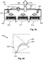
- Figure 4b presents a CIE XYZ color space 450, in which an area between lines 456 and 458 is indicated, where a color point of the visible light may be located.
- a line 452 is drawn, which represents the color point of light of a single wavelength.
- a black body line 454 is drawn.
- the black body line 454 represents color points of electromagnetic radiation emitted by black bodies having a specific temperature.
- light with color points on the black body line 454 are experienced by humans as substantially white light.
- Light, at a maximum distance of 25 SDCM is still experienced by the human naked eye as relatively white with a slight color tint.
- the area, with a maximum distance of 25 SDCM is schematically indicated in Fig. 4b as the area between lines 456 and 458.
- the first light source 110 and the second light source 108 are introduced.
- the second light source 108 and/or the first light source 110 may be a solid state light emitter such as, for example, a Light Emitting Diode (LED), an Organic Light Emitting diode (OLED), or, for example, a laser diode.
- LED Light Emitting Diode
- OLED Organic Light Emitting diode
- laser diode a laser diode
- the lighting assembly 100 may comprise one or more first light sources 110, one or more second light sources 108 and one or more UV filters 104.
- the first light source may comprise a light emitter that emits a specific color of light and one or more luminescent materials that partly convert the light of the specific color of light towards light of one or more other colors.
- the first light source 110 may comprise a plurality of light emitters that each emit, for example, a primary color and in at least one operation mode the emitted mix of primary colors forms the visible light having the defined color point.
- the first light source 110 may comprises a first red emitting LED, a second blue emitting LED and a third green emitting LED.
- Such LEDs emitting a primary color may be controlled with individual control signals such that the obtained color combination has a specific color point.
- the lighting assembly is at least able to emit the visible light having a color point with the above defined maximum distance of 25 SDCM to the black body line. It is not necessary that the lighting assembly always emits the visible light having that color point, but at least emits such light in response to control signal(s) requesting such color point.
- the lighting assembly 100 emits visible light 112 that is well-suitable for illumination because it is capable of emitting relatively white light (because the visible light 112 has a color point within a limited distance of 25 SDCM from the black body line). As defined by the distance to the black body line, the visible light 112 may be off-white light. For example, in specific situations, it is useful to emit bluish white light because it helps people to be more productive, or in other situations, it is useful to emit greenish white light because it helps people to feel more relaxed.
- the visible light 112 is still relatively white to obtain a good illumination of the space and, for example, to have a relatively good color rendering.
- the visible light 112 has a color point within 7 SDCM, or 5 SDCM, from the black body line.
- the visible light 112 having a color point within 25 SDCM from the black body line has a correlated color temperature in a range from 2000 to 20000 Kelvin, or in between 2500 and 10000 Kelvin, or even in between a smaller range of 2700 to 6000 Kelvin.
- visible light has wavelengths in a range from 400 nm to 800 nm.
- the light emission distribution of the visible light 112 may have some tails outside this range and, optionally, at least 90% of all light, emitted by the first light emitting element, is in the range from 400 nm to 800 nm.
- the Color Rending Index of the visible light 112 is at least 60, or at least 70.
- the visible light 112 has a relatively high CRI, for example, at least 80, or at least 85.
- the light assembly 100 also emits UV light 106, 106'.
- the UV light 106 also illuminates the environment.
- the spectral range of the UV light 106, 106' may be limited to the range from 280 nm to 350 nm and, thus, humans, who are in this environment, receive a specific amount of UV light 106 in the spectral range from 280 nm to 350 nm.
- This UV light 106 stimulates the production of Vitamin D in the human skin and, as such, health benefits are obtained.
- the second light source 108 emits a first radiant flux of the UV light 106 and the first light emitting element emits a second radian flux of visible light 112.
- a ratio between the first radiant flux and the second radiant flux is in a range from 0.01 to 0.0001.
- the amount of emitted UV light 106 is relatively low compared to the amount of emitted visible light 112. Thereby, it is prevented that human skin receives too much UV light 106, resulting is possible health risks.
- the second light source 108 may emit UV light in, for example, the above defined spectral range.
- the light distribution of the second light source 108 has tails outside the above discussed spectral range and optionally, at least, 75% of the light energy emitted by the second light source 108 is emitted in the spectral range.
- the second light source emits UV light 106 in a range from 290 nm to 340 nm, and, at least, 65% of the light energy emitted by the second light source 108 is emitted in this range from 290 nm to 340 nm.
- the second light source emits UV light 106 in a range from 295 nm to 335 nm, and, at least, 60% of the light energy emitted by the second light source 108 is emitted in this range from 295 nm to 335 nm.
- the second light source emits UV light 106 in a range from 300 nm to 320 nm and at least 55% of the radiant flux emitted by the second light source 108 is emitted in the range from 300 nm to 320 nm.
- the second light source 108 mainly emits UV-b light and the UV-b light is, optionally, concentrated in a relatively small range (e.g. ⁇ 5nm) around 310 nm, the most effective UV light is emitted for stimulating the Vitamin D production by the human skin, and other forms of possibly harmful UV light are not emitted.
- the amount of UV light 106 emitted is relatively small compared to the amount of visible light 112 emitted. This has been defined by means of a ratio of the first radiant flux of the UV light 106 (in the spectral range) and the second radiant flux of the visible light 112.
- radiant flux is the radiant energy transmitted into the ambient.
- the SI unit of radiant flux is watt (W).
- Radiant fluxes can be measured by means of a calibrated power meter.
- the calibrated power meter and the lighting assembly may be placed in an integrating sphere for obtaining a reliable measurement.
- the power meter or the spectrometer may use filter or gratings to distinguish between different wavelengths.
- a measurement is performed when the power meter is equipped with a filter which allows the emission of light in between 280 nm and 350 nm. Or, for example, several measurements are used which allow the transmission of different, smaller, ranges and the results of the different measurements are combined to one result.
- the radiant fluxes may be measured under different operational conditions, for example, when the lighting assembly is controlled to operate at full power and, for example, when the lighting assembly is controlled to operate at 50% of its maximum power.
- the first radiant flux and the second radiant flux are determined under predefined operational conditions.
- the predefined operational conditions are, for example, the conditions that are defined by the manufacturer of the different light emitting components as the ideal conditions to operate the light emitting components.
- the predefined operational conditions may comprise, at least one of a predefined current provided to the light emitting components, and a predefined voltage provided to the light emitting components, and may also include predefined environmental conditionals like the ambient temperature.
- the ratio between the first radiant flux and the second radiant flux is in between 0.01 and 0.0001.
- the ratio is in between 0.005 and 0.0001.
- the ratio is in between 0.001 and 0.0001.
- the lighting assemblies, the lamp, the light bulb and the light tube of this document are for illumination.
- illumination must be considered as “general illumination”, which means, it is not the illumination of an environment or a product with another specific non-illumination purpose (killing bacteria, growing plants, detecting cracks, medical treatment, tanning) than just illuminating it. It means that when a space is too dark for people to work / live in, and its illumination level must be raised, the embodiments of this document can be used for the purpose of increasing the illumination level of that space such that it is convenient for people to live and work in that space.
- the lighting assemblies, the lamps, the light bulb, the light tube are capable of emitting at least 300 lumens of light.
- the lighting assemblies, the lamps, the light bulb, the light tube are capable of emitting not more than 2000 lumens of light.
- the light exit window is medium sized (e.g. when a multitude of light sources are used in one lighting assembly). In such cases the light exit window is in between 30 to 300 cm 2 . In such cases the light output is in between 1000 and 5000 lumens.
- Luminaires have, in general, also a light output in between 1000 and 5000 lumens of light and their luminaire light output window has often predefined fixed sizes, for example, 50x50cm, 60x60cm or 60x120cm. Thus the luminaire light output windows are in general in between 2500 cm 2 and 7200 cm 2 .
- FIG. 1b schematically shows in a cross-sectional view another embodiment of a lighting assembly 150.
- the lighting assembly 150 is similar to lighting assembly 100 of Fig. 1a .
- a difference is that the UV filter 104 of Fig. 1a is replaced by the UV filter 154.
- the UV filter 254 encloses the first light source 110, thus, the UV filter 254 is brought in direct contact with surfaces of the first light source 110 and, more in particular, the surfaces of the first light source 110 on which the UV light 106, 106' may impinge.
- the UV filter 254 is, in this specific embodiment, a UV filter that absorbs the UV light 106'that impinges on the UV filter 154.
- Inorganic UV absorbers such as ZO,TiO 2 and organic uv absorbers such as (Cetiol® Sensoft, BASF), isopropylpalmitate (BASF), caprylic/capric triglyceride (Myritol® 318, BASF), cocoglycerides (Myritol® 331, BASF), alcohol (96% ethanol, Fluka), phenoxyethanol (Protectol PE, BASF), sodium stearoyl glutatmate (Emulgin® SG, BASF), polyamide-5 (Orgasol Caresse, Arkema), xanthan gum (Keltrol CG RD, CP Kelco), distarch phosphate (Mais PO4PH »B «, Agrana medicine GmbH), sodium acrylates copolymer (and) hydrogenated polydecene (and) PPG-1 trideceth-6 (Tinovis® ADE, BASF), acrylates/beheneth-25 methylacrylate copolymer (
- UV absorbers employed were diethylhexyl butamido triazone, DBT (Uvasorb® HEB, 3V Sigma), Bis-ethylhexyloxyphenol methoxyphenyl triazine, BEMT (Tinosorb® S, BASF), methylene bisbenzotriazolyl tetramethylbutylphenol, MBBT (and) aqua (and) decyl glucoside (and) propylene glycol (and) xanthan gum (Tinosorb® M, BASF), and tris biphenyl triazine, TBPT (Tinosorb® A2B, BASF).
- the UV filter 254 may also be a dichroic reflector.
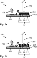
- FIG. 2a schematically shows in a cross-sectional view a further embodiment of a lighting assembly 200.
- the lighting assembly 200 is similar to lighting assembly 150.
- the UV filter 154 of Fig. 1b is replaced by UV filter 204.
- the UV filter 204 acts as a dichroic mirror: the visible light 112 is transmitted through the UV filter 204 and the UV light 106' impinging on the UV filter 204 is reflected and, thus, not transmitted towards the first light source 110'.
- Another different between lighting assembly 150 and lighting assembly 200 is the first light source.
- a first light source 110' is provided that comprises a solid state light emitter packages.
- the first light source 110' comprises package housing 209 which partially encloses a space in which a solid state light emitter 210 (e.g.
- a LED is provided and which space is further filled with a light transmitting material 211 (e.g. Silicone).
- the light transmitting material 211 comprises one or more luminescent materials for at least partially converting the light generated by the solid state light emitter 210 to light of a different wavelength range.
- the solid state light emitter package the solid state light emitter is electrically coupled to power pins (not shown) or power reception areas (now shown) by means of, for example, bonded wires (not shown).
- the solid state light emitter package may also comprise means (not shown) to distribute the heat generated by the solid state light emitter 210 towards the support panel 102 of the lighting assembly.
- the solid state light emitter package has a specific shapes, but different shapes are possible as well, for example, the package housing 209 may be cup-shaped, or the recess in the package housing 209 may be cup-shaped. Also the provided light transmitting material may have other shapes, like the shape of a lens. The current invention is not limited to the shown and mentioned shapes of the solid state light emitter package and other appropriate shapes are possible as well.
- the UV filter 204 protects the whole solid state light emitter package against a possible harmful influence of the UV light 106, 106'.
- Dichoric filters are produced by using layers of dielectric materials such as magnesium fluoride, calcium fluoride, and various metal oxides, which are deposited onto the optical substrate materials.
- FIG. 2b schematically shows in a cross-sectional view another embodiment of a lighting assembly 250.
- the lighting assembly 250 is similar to the lighting assembly 200 of Fig. 2a .
- a difference is that the UV filter 204 of lighting assembly 200 has been replaced by the UV filter 254.
- the UV filter 254 has similar optical characteristics as the UV filter 204 of Fig. 2a and at least an important difference is that the UV filter 254 allows the transmission of oxygen towards the first light source 110'.
- channels 255 are schematically drawn to indicate that the UV filter 254 is at least partly permeable for oxygen, however, it is not necessary that the UV filter 254 has channels to allow the transmission of oxygen towards the first light source 110'.
- Inorganic and organic UV absorbers described above are dispersed/dissolved in a polymer matrix such as silicone rubber, polycarbonate. This way oxygen permeable UV absorbing layers are formed. Permeability values of common polymers are known in the literature. By allowing oxygen to go through disadvantageous effects of UV such as coloring of plastics can be reversed by oxygen induced bleaching reactions.
- FIG 3a schematically shows in a cross-sectional view an embodiment of lighting assembly 300 that comprises a light mixing chamber 304.
- the lighting assembly 300 comprises a housing 302 that has in a wall a light exit window 320.
- the housing encloses the light mixing chamber 304.
- the light exit window 320 is provided with a light transmitting diffusor 310, however, other light transmitting optical elements may also be provided at the light exit window 320.
- the light generated and mixed in the light mixing chamber 304 may be emitted through the light exit window 320 into the ambient of the lighting assembly 300.
- Inner walls 306 of the housing 302 may be light reflective.
- the inner walls 306 may be reflective for the visible light 112 and for the UV light 106.
- the inner walls 306 may be specularly reflective or diffusely reflective.
- a first light source 110 and a second light source 108 At an inner wall of the housing 302, which is the inner wall opposite to the light exit window 320, are provided a first light source 110 and a second light source 108. Embodiments of the first light source 110 and the second light source 108 are discussed in the context of previous embodiments, for example the embodiments of Fig. 1a to Fig. 2b .
- a UV filter 104 At an optical path from the second light source 108 to the first light source 110 is provided a UV filter 104. Embodiments of the UV filter 104 are discussed previously, for example in the context of the embodiments of Fig. 1a to Fig. 2b .
- UV Light emitted by the second light source 108 is not transmitted towards the first light source 110 because the UV filter 104 absorbs and/or reflects the UV light that impinges on the UV filter 104. Visible light 112 generated by the first light source 110 is emitted through the UV filter, through the light exit window, into the ambient of the lighting assembly 300. Thereby, about no UV light 106 impinges on the first light source 110 and, consequently, the quality first light source 110 is not deteriorated because of the damaging character of the UV light.
- the light mixing chamber 104 may reflect portions of the visible light 112 and the UV light 106 one or more times and thereby a more uniform light output is obtained along the light exit window 320 and, thereby, the irradiance levels of the UV light 106 along the light exit window are reduced.
- the diffusor 310 also contributes to a more uniform light output and the prevention of high irradiance levels of UV light 106.
- High irradiance levels of UV light 106 at the light exit window may be dangerous, in particular during misuse when, for example, a user brings lighting assembly 300 in contact with his skin or bring the light exit window directly in front of his eyes.
- the light mixing room 304 contributes to an additional safety of the lighting assembly 300.
- Figure 3b schematically shows in a cross-sectional view another embodiment of lighting assembly 350 that comprises a light mixing chamber 304 that is enclosed by a housing 352.
- the housing 352 has a light exit window 320 which, in the embodiment of Fig. 3b , is provided with a transparent plate 360.
- Other optical elements like the diffusor 310 of Fig. 3a , may also be used at the light exit window 320.
- the inner walls 306 of the housing 352 are light reflective.
- a plurality of first light source 110' and a plurality of second light sources 108 are provided at an inner wall opposite to the light exit window 320.
- Embodiments of the second light sources are discussed previously, for example in the context of the embodiments of Fig.
- the first light sources 110' comprise a solid state light emitter package which are similar to the previously discussed solid state light emitter packages of Fig. 2a and Fig. 2b . Both first light source 110' are enclosed by a UV filter 204 of which possible embodiments have been discussed previously in the context of, for example, the embodiments of Fig. 1a to Fig. 3a .
- the UV light 106 is emitted by the second light sources 106 into the light mixing chamber 304. Subsequently, after zero, one or more reflections, the UV light 106 is transmitted via the light exit window 320 into the ambient of the lighting assembly 350.
- the visible light 112 is emitted by the first light sources 110' into the light mixing chamber 304. Subsequently, after zero, one or more reflections, the visible light 112 is transmitted via the light exit window 320 into the ambient of the lighting assembly 350.
- FIG. 4a schematically shows in a cross-sectional view a further embodiment of lighting assembly 400 that comprises a light mixing chamber 304.
- the lighting assembly 400 of Fig. 4a is similar to the lighting assembly 350 of Fig. 3b .
- the first light sources 110' of lighting assembly 350 of Fig. 3b are replaced by a plurality of solid state light emitter packages 410, 411, 412 which each have a solid state light emitter that emits a specific color of light.
- the different solid state light emitters of the solid state light emitter packages 410, 411, 412 emit red light R, green light G and blue light B, respectively.
- the solid state light emitter package 410, 411, 412 together form the first light source which is capable of emitting in at least one operational mode the visible light having a color point that is not further away than 25 SDCM from the black body line (in the CIEXYZ color space).
- the lighting assembly may receive (not shown) control signals which indicate at which light intensity each one of the solid state light emitter packages 410, 411,412 has to emit and the controller generating the control signals must be able to generate control signals that result in the combined light emission of red light R, green light G and blue light B that has a combined color point within 25 SDCM from the black body line in the CIEXYZ color space.
- the different colors of light R, G, B are emitted into the light mixing chamber 304 and are mixed by the light mixing chamber to obtain a relatively uniform visible light output through the light exit window 320.
- the visible light output through the light exit window is the white light W.
- the lighting assembly 400 also comprises a plurality of second light sources 108 which are arranged at an inner wall of the housing 402 that is adjacent to the light exit window 320.
- the second light sources 108 emit UV light 106 into the light mixing chamber 304 in a direction away from the light exit window 320.
- the UV light is at least once reflected by the reflective inner walls 306 of housing 402.
- the solid state light emitter packages 410, 411, 412 are provided with an UV filter 204.
- Embodiments of UV filters 204 are discussed previously in the context of the embodiments of Fig. 1a to Fig. 3b .
- the UV light 106 is first emitted into the direction of the reflective inner walls 306 of the housing 402 and, thus, also into the direction of the solid state light emitter package 410, 411, 412.
- the UV filters 204 protect the solid state light emitter packages 410, 411, 412 from being damaged by the UV light 106.
- the UV filter 204 are dichroic mirrors which allow the transmission of the visible light that is generated by the respective solid state light emitter packages 410, 411, 412 and which reflect the UV light 106. In such an embodiment the efficiency of the lighting assembly 400 is kept relatively high.
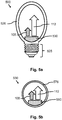
- FIG. 5a schematically shows in a cross-sectional view an embodiment of a retrofit light bulb 500.
- the retrofit light bulb 500 comprises a light transmitting bulb 526 that is provided on a base 528 that allows the retrofit light bulb to connect with a (power-)socket for a lamp in the same way as traditional light bulbs do.
- a lighting assembly 530 according to one of the previous discussed embodiments of the lighting assembly.
- the lighting assembly 530 emits the UV light 108 and the visible light 112 into the interior of the bulb 526 and, subsequently, the UV light 108 and the visible light 112 are emitted through the bulb 526 into the ambient of the retrofit light bulb 500.
- the lighting assembly 530 is present in the bulb 526 adjacent to the base 528, but other positions may be possible as well. Also it is not necessary that the first light source and the second light source of the lighting assembly are provided in the bulb 526 at a position close to each other. It is, for example, also possible that the first light source is arranged at a position in the bulb 526 opposite to the second light source.
- FIG. 5b schematically shows in a cross-sectional view an embodiment of a retrofit light tube 550.
- the retrofit light tube 550 comprises a light transmitting tube 576 in which a lighting assembly 580 according to previously discussed embodiments is provided.
- the lighting assembly 580 emits the UV light 108 and the visible light 112 into the interior of the tube 576 and is, subsequently, emitted through the tube 576 into the ambient of the retrofit light tube 550.
- the first light source and the second light source are arranged at a position relatively close to each other inside the tube 576.
- the first light source(s) and second light source(s) may also be arranged at spatially separated locations in the longitudinal direction of the tube 576 and/or may be arranged at opposite positions (in the radial direction) inside the tube 576.
- the retrofit light tube 550 is suitable for use in luminaires that are designed for use with traditional light tubes.
- the retrofit light tube 550 and the retrofit light bulb 500 are examples of lamps that comprise the lighting assembly according to previously discussed embodiments.
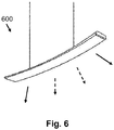
- FIG. 6 schematically shows a 3d view of a luminaire 600.
- the luminaire 600 is provided with a lighting assembly according to one of the previously discussed embodiments of such a lighting assembly, a retrofit light bulb 500 as discussed in the context of Fig. 5a or a retrofit light tube 550 as discussed in the context of Fig. 5b .
- the lighting assembly comprises a first light source, a second light source and an UV filter.
- the first light source emits in operation visible light.
- the second light source emits in operation UV light.
- the UV filter allows a transmission of visible light and absorbs or reflects UV light.
- the UV filter is arranged in an optical path from the second light source towards the first light source to prevent the UV light to impinge on the first light source while allowing the emission of the UV light into the ambient of the lighting assembly.
Landscapes
- Engineering & Computer Science (AREA)
- Microelectronics & Electronic Packaging (AREA)
- Physics & Mathematics (AREA)
- Power Engineering (AREA)
- General Engineering & Computer Science (AREA)
- Computer Hardware Design (AREA)
- Optics & Photonics (AREA)
- Condensed Matter Physics & Semiconductors (AREA)
- General Physics & Mathematics (AREA)
- Manufacturing & Machinery (AREA)
- Spectroscopy & Molecular Physics (AREA)
- Non-Portable Lighting Devices Or Systems Thereof (AREA)
- Radiation-Therapy Devices (AREA)
Claims (15)
- Ensemble d'éclairage (100, 150, 200, 250, 300, 350, 400, 530, 580) pour une illumination, l'ensemble d'éclairage (100, 150, 200, 250, 300, 350, 400, 530, 580) comprenant :- une première source de lumière (110, 110', 410, 411, 412) pour émettre de la lumière visible (112, R, G, B, W), la première source de lumière (110, 110', 410, 411, 412) comprenant un émetteur de lumière (210) et un ou plusieurs matériaux luminescents,- une seconde source de lumière (108) pour émettre de la lumière UV (106, 106'), caractérisée par un filtre UV (104, 154, 204, 254) permettant une transmission de lumière visible (112, R, G, B, W) et absorbant ou réfléchissant la lumière UV (106'),
dans lequel le filtre UV (104, 154, 204, 254) est agencé dans un trajet optique à partir de la seconde source de lumière (108) en direction de la première source de lumière (110, 110', 410, 411, 412). - Ensemble d'éclairage (100, 150, 200, 250, 300, 350, 400, 530, 580) selon la revendication 1, dans lequel le filtre UV (104, 154, 204, 254) entoure ou renferme la première source de lumière (110, 110', 410, 411, 412).
- Ensemble d'éclairage (100, 150, 200, 250, 300, 350, 400, 530, 580) selon l'une quelconque des revendications précédentes dans lequel la première source de lumière (110, 110', 410, 411, 412) comprend un lot d'émetteurs de lumière à l'état solide comprenant un émetteur de lumière à l'état solide (210) pour émettre la lumière visible (112, R, G, B, W), le lot d'émetteurs de lumière à l'état solide étant renfermé par le filtre UV (104, 154, 204, 254).
- Ensemble d'éclairage (100, 150, 200, 250, 300, 350, 400, 530, 580) selon l'une quelconque des revendications précédentes dans lequel le filtre UV (254) permet la transmission d'oxygène en direction de la seconde source de lumière (108).
- Ensemble d'éclairage (100, 150, 200, 250, 300, 350, 400, 530, 580) selon l'une quelconque des revendications précédentes comprenant :- un boîtier (302, 352, 402), une fenêtre de sortie de lumière (320) étant fournie dans une paroi du boîtier (302, 352, 402) pour permettre la transmission de la lumière visible (112, R, G, B, W) et la lumière UV (106, 106') à l'intérieur de l'environnement de l'ensemble d'éclairage (100, 150, 200, 250, 300, 350, 400, 530, 580), et une chambre de mélange de lumière (304) étant fournie à l'intérieur du boîtier (302, 352, 402) pour mélanger de la lumière émise par la première source de lumière (110, 110', 410, 411, 412) et par la seconde source de lumière (108),
dans lequel la première source de lumière (110, 110', 410, 411, 412) et la seconde source de lumière (108) sont fournies au sein de la chambre de mélange de lumière (304). - Ensemble d'éclairage (100, 150, 200, 250, 300, 350, 400, 530, 580) selon la revendication 5, dans lequel la première source de lumière (110, 110', 410, 411, 412) est agencée sur une paroi de la chambre de mélange de lumière (304) à l'opposé de la fenêtre de sortie de lumière (320) et, une ou plusieurs surfaces de la première source de lumière (110, 110', 410, 411, 412) n'étant pas en contact avec la paroi sont dotées du filtre UV (104, 154, 204, 254).
- Ensemble d'éclairage (100, 150, 200, 250, 300, 350, 400, 530, 580) selon la revendication 5 ou 6, dans lequel la seconde source de lumière (108) est agencée au niveau d'une position à l'intérieur de la chambre de mélange de lumière (304) pour empêcher une émission direction de la lumière UV (106, 106') à travers la fenêtre de sortie de lumière (320).
- Ensemble d'éclairage (100, 150, 200, 250, 300, 350, 400, 530, 580) selon l'une quelconque des revendications précédentes comprenant au moins un parmi les suivantes :- une pluralité de premières sources de lumière (110, 110', 410, 411, 412),- une pluralité de secondes sources de lumière (108),- une pluralité de filtres UV (104, 154, 204, 254),
dans lequel, si l'ensemble d'éclairage (100, 150, 200, 250, 300, 350, 400, 530, 580) comprend une pluralité de de premières sources de lumière (110, 110', 410, 411, 412) et/ou si l'ensemble d'éclairage (100, 150, 200, 250, 300, 350, 400, 530, 580) comprend une pluralité de secondes sources de lumière (108), le filtre UV (104, 154, 204, 254) selon la revendication 1 est agencé pour ou la pluralité de filtres UV (104, 154, 204, 254) est agencée pour bloquer la transmission de lumière UV (106') le long des trajets optiques à partir des secondes sources de lumière (108) en direction des premières sources de lumière (110, 110', 410, 411, 412). - Ensemble d'éclairage (100, 150, 200, 250, 300, 350, 400, 530, 580) selon l'une quelconque des revendications précédentes, dans lequel la première source de lumière (110, 110', 410, 411, 412) est capable d'émettre de la lumière visible (112, R, G, B, W) présentant un point de couleur dans l'espace colorimétrique CIE XYZ au sein d'une distance inférieure à 25 SDCM par rapport à la ligne de corps noire (454) dans ledit espace colorimétrique.
- Ensemble d'éclairage (100, 150, 200, 250, 300, 350, 400, 530, 580) selon l'une quelconque des revendications précédentes, l'ensemble d'éclairage (100, 150, 200, 250, 300, 350, 400, 530, 580) comprenant une fenêtre de sortie de lumière (320), dans lequel l'ensemble d'éclairage (100, 150, 200, 250, 300, 350, 400, 530, 580) est configuré pour émettre, en fonctionnement, une quantité de lumière UV (106, 106') à travers la fenêtre de sortie de lumière (320), la quantité de lumière UV (106, 106') présentant un premier flux énergétique et l'ensemble d'éclairage (100, 150, 200, 250, 300, 350, 400, 530, 580) est configuré pour émettre un second flux énergétique de la lumière visible (112, R, G, B, W) à travers la fenêtre de sortie de lumière (320), un rapport entre le premier flux énergétique et le second flux énergétique se trouve dans une plage allant de 0,01 à 0,0001.
- Ensemble d'éclairage (100, 150, 200, 250, 300, 350, 400, 530, 580) selon l'une quelconque des revendications précédentes, dans lequel la lumière UV (106, 106') comprenant de la lumière dans une plage spectrale allant de 280 nm à 350 nm.
- Lampe (500, 550) pour une illumination comprenant l'ensemble d'éclairage (100, 150, 200, 250, 300, 350, 400, 530, 580) selon l'une quelconque des revendications 1 à 11.
- Ampoule rétrofit (500) pour une illumination, l'ampoule rétrofit (500) comprenant une ampoule transmettant de la lumière (526) et l'ensemble d'éclairage (100, 150, 200, 250, 300, 350, 400, 530, 580) selon l'une quelconque des revendications 1 à 11.
- Tube lumineux rétrofit (550) pour une illumination, le tube lumineux (550) comprenant un tube transmettant de la lumière (576) et l'ensemble d'éclairage (100, 150, 200, 250, 300, 350, 400, 530, 580) selon l'une quelconque des revendications 1 à 11.
- Luminaire (660) pour une illumination comprenant l'ensemble d'éclairage (100, 150, 200, 250, 300, 350, 400, 530, 580) selon l'une quelconque des revendications 1 à 11, ou une lampe (500, 550) selon la revendication 12, ou une ampoule rétrofit (500) selon la revendication 13, ou un tube lumineux rétrofit (550) selon la revendication 14.
Applications Claiming Priority (2)
| Application Number | Priority Date | Filing Date | Title |
|---|---|---|---|
| EP15177988 | 2015-07-23 | ||
| PCT/EP2016/064858 WO2017012829A1 (fr) | 2015-07-23 | 2016-06-27 | Ensemble d'éclairage à source de lumière protégée des uv émettant de la lumière visible |
Publications (2)
| Publication Number | Publication Date |
|---|---|
| EP3326213A1 EP3326213A1 (fr) | 2018-05-30 |
| EP3326213B1 true EP3326213B1 (fr) | 2020-05-06 |
Family
ID=53761976
Family Applications (1)
| Application Number | Title | Priority Date | Filing Date |
|---|---|---|---|
| EP16732609.9A Active EP3326213B1 (fr) | 2015-07-23 | 2016-06-27 | Ensemble d'éclairage avec source de lumière protégée des uv qui émet de la lumière visible |
Country Status (6)
| Country | Link |
|---|---|
| US (1) | US10551032B2 (fr) |
| EP (1) | EP3326213B1 (fr) |
| JP (1) | JP6818006B2 (fr) |
| CN (1) | CN107851692B (fr) |
| DK (1) | DK3326213T3 (fr) |
| WO (1) | WO2017012829A1 (fr) |
Families Citing this family (12)
| Publication number | Priority date | Publication date | Assignee | Title |
|---|---|---|---|---|
| US10918747B2 (en) * | 2015-07-30 | 2021-02-16 | Vital Vio, Inc. | Disinfecting lighting device |
| KR20190012555A (ko) | 2017-07-27 | 2019-02-11 | 서울바이오시스 주식회사 | 조명 장치 |
| KR102230459B1 (ko) * | 2017-09-06 | 2021-03-23 | 지엘비텍 주식회사 | D50, d65 고연색성 표준 led 발광 모듈 및 조명 장치 |
| EP3691972B1 (fr) * | 2017-10-06 | 2024-02-21 | Bombardier Inc. | Procédé de désinfection de cabine d'aéronef à l'aide d'un ensemble d'éclairage, et ensemble d'éclairage associé |
| US11996500B2 (en) | 2018-12-26 | 2024-05-28 | Seoul Viosys Co., Ltd. | LED lighting apparatus having additional function |
| WO2021074970A1 (fr) * | 2019-10-15 | 2021-04-22 | 株式会社日立ハイテク | Dispositif de traitement d'échantillon d'acide nucléique et procédé de traitement d'échantillon d'acide nucléique |
| US11628234B2 (en) * | 2020-06-01 | 2023-04-18 | Know Labs, Inc. | White light LED light bulbs for ambient lighting and pathogen inactivation |
| US11224107B1 (en) * | 2020-06-23 | 2022-01-11 | Return To Play Inc | Replacement LED light bulbs with ultraviolet emission |
| JP6905656B1 (ja) * | 2020-11-16 | 2021-07-21 | デービット・エー.・リーブレック | 照明装置 |
| EP4366788A1 (fr) * | 2021-07-05 | 2024-05-15 | Signify Holding B.V. | Dispositif d'éclairage de désinfection, lampe et appareil d'éclairage utilisant une lumière uv |
| WO2023285268A1 (fr) * | 2021-07-16 | 2023-01-19 | Signify Holding B.V. | Dispositif d'éclairage de désinfection hybride |
| WO2023161108A1 (fr) | 2022-02-22 | 2023-08-31 | Signify Holding B.V. | Source lumineuse hybride uv-blanche |
Family Cites Families (9)
| Publication number | Priority date | Publication date | Assignee | Title |
|---|---|---|---|---|
| US6686676B2 (en) * | 2001-04-30 | 2004-02-03 | General Electric Company | UV reflectors and UV-based light sources having reduced UV radiation leakage incorporating the same |
| JP2006310771A (ja) | 2005-03-30 | 2006-11-09 | Toshiba Discrete Technology Kk | 半導体発光装置 |
| JP5508417B2 (ja) | 2008-08-07 | 2014-05-28 | コーニンクレッカ フィリップス エヌ ヴェ | 動的な照明効果を備える照明装置 |
| EP2331869B1 (fr) * | 2008-09-23 | 2015-04-22 | Koninklijke Philips N.V. | Dispositif d'éclairage muni d'un élément de diffusion à variation électrique |
| CN103471003A (zh) * | 2010-02-23 | 2013-12-25 | 亿光电子工业股份有限公司 | 光源模块 |
| US9140429B2 (en) * | 2010-10-14 | 2015-09-22 | Cree, Inc. | Optical element edge treatment for lighting device |
| EP2841849A2 (fr) * | 2012-04-25 | 2015-03-04 | Koninklijke Philips N.V. | Ensemble d'éclairage destiné à fournir une apparence colorée neutre, lampe et luminaire |
| TWI523277B (zh) * | 2013-07-12 | 2016-02-21 | White light emitting diode module with ultraviolet light | |
| CN203810092U (zh) | 2014-05-22 | 2014-09-03 | 黄河 | 一种紫外线探伤灯 |
-
2016
- 2016-06-27 WO PCT/EP2016/064858 patent/WO2017012829A1/fr active Application Filing
- 2016-06-27 JP JP2018502209A patent/JP6818006B2/ja active Active
- 2016-06-27 DK DK16732609.9T patent/DK3326213T3/da active
- 2016-06-27 CN CN201680043142.3A patent/CN107851692B/zh active Active
- 2016-06-27 US US15/745,286 patent/US10551032B2/en active Active
- 2016-06-27 EP EP16732609.9A patent/EP3326213B1/fr active Active
Non-Patent Citations (1)
| Title |
|---|
| None * |
Also Published As
| Publication number | Publication date |
|---|---|
| WO2017012829A1 (fr) | 2017-01-26 |
| US20180209609A1 (en) | 2018-07-26 |
| CN107851692A (zh) | 2018-03-27 |
| CN107851692B (zh) | 2021-07-30 |
| US10551032B2 (en) | 2020-02-04 |
| DK3326213T3 (da) | 2020-07-27 |
| EP3326213A1 (fr) | 2018-05-30 |
| JP2018524783A (ja) | 2018-08-30 |
| JP6818006B2 (ja) | 2021-01-20 |
Similar Documents
| Publication | Publication Date | Title |
|---|---|---|
| EP3326213B1 (fr) | Ensemble d'éclairage avec source de lumière protégée des uv qui émet de la lumière visible | |
| CN107810362B (zh) | 发射一部分uv光的照明组件 | |
| US10753575B2 (en) | Single diode disinfection | |
| RU2634699C1 (ru) | Светоизлучающий модуль, лампа, светильник и способ освещения объекта | |
| US10288233B2 (en) | Inverse visible spectrum light and broad spectrum light source for enhanced vision | |
| CN101793355B (zh) | 远程荧光体发光二极管照明系统 | |
| US20150162505A1 (en) | Inverse visible spectrum light and broad spectrum light source for enhanced vision | |
| CN107111221A (zh) | 具有波长转换装置的照明设备 | |
| TW201734418A (zh) | 基於複合紫外光led及磷光劑的高光譜校準器 | |
| CN107084318A (zh) | 具有均匀照亮的外观的基于led的直视照明器 | |
| WO2020039215A1 (fr) | Appareil d'éclairage | |
| WO2019140309A1 (fr) | Systèmes commutables pour lumière blanche à haut rendu de couleurs et à effets biologiques | |
| WO2014030148A2 (fr) | Ensemble électroluminescent, lampe et luminaire | |
| EP3837468A1 (fr) | Simulateur solaire | |
| EP3312892A1 (fr) | Luminaire comprenant une pluralité de sources lumineuses différentes avec la même apparence en état éteint | |
| WO2009083853A1 (fr) | Système d'éclairage | |
| WO2020027783A1 (fr) | Systèmes et procédés pour fournir une lumière blanche chaude accordable | |
| WO2018179105A1 (fr) | Procédé de fabrication de dispositif d'éclairage | |
| JP6760007B2 (ja) | 光源装置 | |
| US8779448B2 (en) | Illumination system with light source, radiation converting element and filter | |
| CN217559593U (zh) | 用于可见光和紫光或紫外发射的光源及用于该光源的系统 | |
| WO2023145695A1 (fr) | Dispositif électroluminescent et système de détection | |
| WO2023161108A1 (fr) | Source lumineuse hybride uv-blanche | |
| WO2020111051A1 (fr) | Dispositif d'éclairage | |
| Jennato et al. | Considerations in LED photometry |
Legal Events
| Date | Code | Title | Description |
|---|---|---|---|
| STAA | Information on the status of an ep patent application or granted ep patent |
Free format text: STATUS: THE INTERNATIONAL PUBLICATION HAS BEEN MADE |
|
| PUAI | Public reference made under article 153(3) epc to a published international application that has entered the european phase |
Free format text: ORIGINAL CODE: 0009012 |
|
| STAA | Information on the status of an ep patent application or granted ep patent |
Free format text: STATUS: REQUEST FOR EXAMINATION WAS MADE |
|
| 17P | Request for examination filed |
Effective date: 20180223 |
|
| AK | Designated contracting states |
Kind code of ref document: A1 Designated state(s): AL AT BE BG CH CY CZ DE DK EE ES FI FR GB GR HR HU IE IS IT LI LT LU LV MC MK MT NL NO PL PT RO RS SE SI SK SM TR |
|
| AX | Request for extension of the european patent |
Extension state: BA ME |
|
| DAV | Request for validation of the european patent (deleted) | ||
| DAX | Request for extension of the european patent (deleted) | ||
| RAP1 | Party data changed (applicant data changed or rights of an application transferred) |
Owner name: PHILIPS LIGHTING HOLDING B.V. |
|
| RAP1 | Party data changed (applicant data changed or rights of an application transferred) |
Owner name: SIGNIFY HOLDING B.V. |
|
| GRAP | Despatch of communication of intention to grant a patent |
Free format text: ORIGINAL CODE: EPIDOSNIGR1 |
|
| STAA | Information on the status of an ep patent application or granted ep patent |
Free format text: STATUS: GRANT OF PATENT IS INTENDED |
|
| INTG | Intention to grant announced |
Effective date: 20191204 |
|
| GRAS | Grant fee paid |
Free format text: ORIGINAL CODE: EPIDOSNIGR3 |
|
| GRAA | (expected) grant |
Free format text: ORIGINAL CODE: 0009210 |
|
| STAA | Information on the status of an ep patent application or granted ep patent |
Free format text: STATUS: THE PATENT HAS BEEN GRANTED |
|
| AK | Designated contracting states |
Kind code of ref document: B1 Designated state(s): AL AT BE BG CH CY CZ DE DK EE ES FI FR GB GR HR HU IE IS IT LI LT LU LV MC MK MT NL NO PL PT RO RS SE SI SK SM TR |
|
| REG | Reference to a national code |
Ref country code: GB Ref legal event code: FG4D |
|
| REG | Reference to a national code |
Ref country code: CH Ref legal event code: EP Ref country code: AT Ref legal event code: REF Ref document number: 1268246 Country of ref document: AT Kind code of ref document: T Effective date: 20200515 |
|
| REG | Reference to a national code |
Ref country code: IE Ref legal event code: FG4D |
|
| REG | Reference to a national code |
Ref country code: DE Ref legal event code: R096 Ref document number: 602016035783 Country of ref document: DE |
|
| REG | Reference to a national code |
Ref country code: DK Ref legal event code: T3 Effective date: 20200720 |
|
| REG | Reference to a national code |
Ref country code: LT Ref legal event code: MG4D |
|
| REG | Reference to a national code |
Ref country code: NL Ref legal event code: MP Effective date: 20200506 |
|
| PG25 | Lapsed in a contracting state [announced via postgrant information from national office to epo] |
Ref country code: PT Free format text: LAPSE BECAUSE OF FAILURE TO SUBMIT A TRANSLATION OF THE DESCRIPTION OR TO PAY THE FEE WITHIN THE PRESCRIBED TIME-LIMIT Effective date: 20200907 Ref country code: IS Free format text: LAPSE BECAUSE OF FAILURE TO SUBMIT A TRANSLATION OF THE DESCRIPTION OR TO PAY THE FEE WITHIN THE PRESCRIBED TIME-LIMIT Effective date: 20200906 Ref country code: SE Free format text: LAPSE BECAUSE OF FAILURE TO SUBMIT A TRANSLATION OF THE DESCRIPTION OR TO PAY THE FEE WITHIN THE PRESCRIBED TIME-LIMIT Effective date: 20200506 Ref country code: NO Free format text: LAPSE BECAUSE OF FAILURE TO SUBMIT A TRANSLATION OF THE DESCRIPTION OR TO PAY THE FEE WITHIN THE PRESCRIBED TIME-LIMIT Effective date: 20200806 Ref country code: FI Free format text: LAPSE BECAUSE OF FAILURE TO SUBMIT A TRANSLATION OF THE DESCRIPTION OR TO PAY THE FEE WITHIN THE PRESCRIBED TIME-LIMIT Effective date: 20200506 Ref country code: GR Free format text: LAPSE BECAUSE OF FAILURE TO SUBMIT A TRANSLATION OF THE DESCRIPTION OR TO PAY THE FEE WITHIN THE PRESCRIBED TIME-LIMIT Effective date: 20200807 Ref country code: LT Free format text: LAPSE BECAUSE OF FAILURE TO SUBMIT A TRANSLATION OF THE DESCRIPTION OR TO PAY THE FEE WITHIN THE PRESCRIBED TIME-LIMIT Effective date: 20200506 |
|
| PG25 | Lapsed in a contracting state [announced via postgrant information from national office to epo] |
Ref country code: LV Free format text: LAPSE BECAUSE OF FAILURE TO SUBMIT A TRANSLATION OF THE DESCRIPTION OR TO PAY THE FEE WITHIN THE PRESCRIBED TIME-LIMIT Effective date: 20200506 Ref country code: BG Free format text: LAPSE BECAUSE OF FAILURE TO SUBMIT A TRANSLATION OF THE DESCRIPTION OR TO PAY THE FEE WITHIN THE PRESCRIBED TIME-LIMIT Effective date: 20200806 Ref country code: RS Free format text: LAPSE BECAUSE OF FAILURE TO SUBMIT A TRANSLATION OF THE DESCRIPTION OR TO PAY THE FEE WITHIN THE PRESCRIBED TIME-LIMIT Effective date: 20200506 Ref country code: HR Free format text: LAPSE BECAUSE OF FAILURE TO SUBMIT A TRANSLATION OF THE DESCRIPTION OR TO PAY THE FEE WITHIN THE PRESCRIBED TIME-LIMIT Effective date: 20200506 |
|
| REG | Reference to a national code |
Ref country code: AT Ref legal event code: MK05 Ref document number: 1268246 Country of ref document: AT Kind code of ref document: T Effective date: 20200506 |
|
| PG25 | Lapsed in a contracting state [announced via postgrant information from national office to epo] |
Ref country code: NL Free format text: LAPSE BECAUSE OF FAILURE TO SUBMIT A TRANSLATION OF THE DESCRIPTION OR TO PAY THE FEE WITHIN THE PRESCRIBED TIME-LIMIT Effective date: 20200506 Ref country code: AL Free format text: LAPSE BECAUSE OF FAILURE TO SUBMIT A TRANSLATION OF THE DESCRIPTION OR TO PAY THE FEE WITHIN THE PRESCRIBED TIME-LIMIT Effective date: 20200506 |
|
| PG25 | Lapsed in a contracting state [announced via postgrant information from national office to epo] |
Ref country code: SM Free format text: LAPSE BECAUSE OF FAILURE TO SUBMIT A TRANSLATION OF THE DESCRIPTION OR TO PAY THE FEE WITHIN THE PRESCRIBED TIME-LIMIT Effective date: 20200506 Ref country code: EE Free format text: LAPSE BECAUSE OF FAILURE TO SUBMIT A TRANSLATION OF THE DESCRIPTION OR TO PAY THE FEE WITHIN THE PRESCRIBED TIME-LIMIT Effective date: 20200506 Ref country code: ES Free format text: LAPSE BECAUSE OF FAILURE TO SUBMIT A TRANSLATION OF THE DESCRIPTION OR TO PAY THE FEE WITHIN THE PRESCRIBED TIME-LIMIT Effective date: 20200506 Ref country code: AT Free format text: LAPSE BECAUSE OF FAILURE TO SUBMIT A TRANSLATION OF THE DESCRIPTION OR TO PAY THE FEE WITHIN THE PRESCRIBED TIME-LIMIT Effective date: 20200506 Ref country code: RO Free format text: LAPSE BECAUSE OF FAILURE TO SUBMIT A TRANSLATION OF THE DESCRIPTION OR TO PAY THE FEE WITHIN THE PRESCRIBED TIME-LIMIT Effective date: 20200506 Ref country code: CZ Free format text: LAPSE BECAUSE OF FAILURE TO SUBMIT A TRANSLATION OF THE DESCRIPTION OR TO PAY THE FEE WITHIN THE PRESCRIBED TIME-LIMIT Effective date: 20200506 |
|
| REG | Reference to a national code |
Ref country code: CH Ref legal event code: PL |
|
| REG | Reference to a national code |
Ref country code: DE Ref legal event code: R097 Ref document number: 602016035783 Country of ref document: DE |
|
| PG25 | Lapsed in a contracting state [announced via postgrant information from national office to epo] |
Ref country code: PL Free format text: LAPSE BECAUSE OF FAILURE TO SUBMIT A TRANSLATION OF THE DESCRIPTION OR TO PAY THE FEE WITHIN THE PRESCRIBED TIME-LIMIT Effective date: 20200506 Ref country code: SK Free format text: LAPSE BECAUSE OF FAILURE TO SUBMIT A TRANSLATION OF THE DESCRIPTION OR TO PAY THE FEE WITHIN THE PRESCRIBED TIME-LIMIT Effective date: 20200506 Ref country code: MC Free format text: LAPSE BECAUSE OF FAILURE TO SUBMIT A TRANSLATION OF THE DESCRIPTION OR TO PAY THE FEE WITHIN THE PRESCRIBED TIME-LIMIT Effective date: 20200506 |
|
| PLBE | No opposition filed within time limit |
Free format text: ORIGINAL CODE: 0009261 |
|
| STAA | Information on the status of an ep patent application or granted ep patent |
Free format text: STATUS: NO OPPOSITION FILED WITHIN TIME LIMIT |
|
| PG25 | Lapsed in a contracting state [announced via postgrant information from national office to epo] |
Ref country code: LU Free format text: LAPSE BECAUSE OF NON-PAYMENT OF DUE FEES Effective date: 20200627 |
|
| 26N | No opposition filed |
Effective date: 20210209 |
|
| REG | Reference to a national code |
Ref country code: BE Ref legal event code: MM Effective date: 20200630 |
|
| PG25 | Lapsed in a contracting state [announced via postgrant information from national office to epo] |
Ref country code: IE Free format text: LAPSE BECAUSE OF NON-PAYMENT OF DUE FEES Effective date: 20200627 Ref country code: CH Free format text: LAPSE BECAUSE OF NON-PAYMENT OF DUE FEES Effective date: 20200630 Ref country code: LI Free format text: LAPSE BECAUSE OF NON-PAYMENT OF DUE FEES Effective date: 20200630 |
|
| PG25 | Lapsed in a contracting state [announced via postgrant information from national office to epo] |
Ref country code: SI Free format text: LAPSE BECAUSE OF FAILURE TO SUBMIT A TRANSLATION OF THE DESCRIPTION OR TO PAY THE FEE WITHIN THE PRESCRIBED TIME-LIMIT Effective date: 20200506 Ref country code: BE Free format text: LAPSE BECAUSE OF NON-PAYMENT OF DUE FEES Effective date: 20200630 |
|
| PG25 | Lapsed in a contracting state [announced via postgrant information from national office to epo] |
Ref country code: TR Free format text: LAPSE BECAUSE OF FAILURE TO SUBMIT A TRANSLATION OF THE DESCRIPTION OR TO PAY THE FEE WITHIN THE PRESCRIBED TIME-LIMIT Effective date: 20200506 Ref country code: MT Free format text: LAPSE BECAUSE OF FAILURE TO SUBMIT A TRANSLATION OF THE DESCRIPTION OR TO PAY THE FEE WITHIN THE PRESCRIBED TIME-LIMIT Effective date: 20200506 Ref country code: CY Free format text: LAPSE BECAUSE OF FAILURE TO SUBMIT A TRANSLATION OF THE DESCRIPTION OR TO PAY THE FEE WITHIN THE PRESCRIBED TIME-LIMIT Effective date: 20200506 |
|
| PG25 | Lapsed in a contracting state [announced via postgrant information from national office to epo] |
Ref country code: MK Free format text: LAPSE BECAUSE OF FAILURE TO SUBMIT A TRANSLATION OF THE DESCRIPTION OR TO PAY THE FEE WITHIN THE PRESCRIBED TIME-LIMIT Effective date: 20200506 |
|
| P01 | Opt-out of the competence of the unified patent court (upc) registered |
Effective date: 20230425 |
|
| PGFP | Annual fee paid to national office [announced via postgrant information from national office to epo] |
Ref country code: FR Payment date: 20230622 Year of fee payment: 8 Ref country code: DK Payment date: 20230621 Year of fee payment: 8 |
|
| PGFP | Annual fee paid to national office [announced via postgrant information from national office to epo] |
Ref country code: IT Payment date: 20230620 Year of fee payment: 8 Ref country code: GB Payment date: 20230620 Year of fee payment: 8 |
|
| PGFP | Annual fee paid to national office [announced via postgrant information from national office to epo] |
Ref country code: DE Payment date: 20230828 Year of fee payment: 8 |