EP3326031B1 - Ellipse-like aperture for a camera lens assembly or for a photo or film camera - Google Patents
Ellipse-like aperture for a camera lens assembly or for a photo or film camera Download PDFInfo
- Publication number
- EP3326031B1 EP3326031B1 EP16741250.1A EP16741250A EP3326031B1 EP 3326031 B1 EP3326031 B1 EP 3326031B1 EP 16741250 A EP16741250 A EP 16741250A EP 3326031 B1 EP3326031 B1 EP 3326031B1
- Authority
- EP
- European Patent Office
- Prior art keywords
- diaphragm
- elliptical
- opening
- iris
- anamorphic
- Prior art date
- Legal status (The legal status is an assumption and is not a legal conclusion. Google has not performed a legal analysis and makes no representation as to the accuracy of the status listed.)
- Active
Links
- 230000005540 biological transmission Effects 0.000 claims description 4
- 230000000694 effects Effects 0.000 description 29
- 230000006835 compression Effects 0.000 description 21
- 238000007906 compression Methods 0.000 description 21
- 241000446313 Lamella Species 0.000 description 13
- 230000003287 optical effect Effects 0.000 description 10
- 230000033001 locomotion Effects 0.000 description 8
- 238000001454 recorded image Methods 0.000 description 7
- 230000000007 visual effect Effects 0.000 description 5
- 230000004075 alteration Effects 0.000 description 4
- 238000000034 method Methods 0.000 description 4
- 230000008859 change Effects 0.000 description 3
- 230000008569 process Effects 0.000 description 3
- 238000010276 construction Methods 0.000 description 2
- 230000008878 coupling Effects 0.000 description 2
- 238000010168 coupling process Methods 0.000 description 2
- 238000005859 coupling reaction Methods 0.000 description 2
- 238000006073 displacement reaction Methods 0.000 description 2
- 238000005562 fading Methods 0.000 description 2
- 238000004519 manufacturing process Methods 0.000 description 2
- 238000013459 approach Methods 0.000 description 1
- 230000001419 dependent effect Effects 0.000 description 1
- 230000000750 progressive effect Effects 0.000 description 1
- 230000009467 reduction Effects 0.000 description 1
- 230000008719 thickening Effects 0.000 description 1
Images


Classifications
-
- G—PHYSICS
- G03—PHOTOGRAPHY; CINEMATOGRAPHY; ANALOGOUS TECHNIQUES USING WAVES OTHER THAN OPTICAL WAVES; ELECTROGRAPHY; HOLOGRAPHY
- G03B—APPARATUS OR ARRANGEMENTS FOR TAKING PHOTOGRAPHS OR FOR PROJECTING OR VIEWING THEM; APPARATUS OR ARRANGEMENTS EMPLOYING ANALOGOUS TECHNIQUES USING WAVES OTHER THAN OPTICAL WAVES; ACCESSORIES THEREFOR
- G03B9/00—Exposure-making shutters; Diaphragms
- G03B9/02—Diaphragms
- G03B9/06—Two or more co-operating pivoted blades, e.g. iris type
-
- B—PERFORMING OPERATIONS; TRANSPORTING
- B62—LAND VEHICLES FOR TRAVELLING OTHERWISE THAN ON RAILS
- B62J—CYCLE SADDLES OR SEATS; AUXILIARY DEVICES OR ACCESSORIES SPECIALLY ADAPTED TO CYCLES AND NOT OTHERWISE PROVIDED FOR, e.g. ARTICLE CARRIERS OR CYCLE PROTECTORS
- B62J17/00—Weather guards for riders; Fairings or stream-lining parts not otherwise provided for
- B62J17/02—Weather guards for riders; Fairings or stream-lining parts not otherwise provided for shielding only the rider's front
- B62J17/04—Windscreens
-
- G—PHYSICS
- G02—OPTICS
- G02B—OPTICAL ELEMENTS, SYSTEMS OR APPARATUS
- G02B5/00—Optical elements other than lenses
- G02B5/005—Diaphragms
-
- G—PHYSICS
- G03—PHOTOGRAPHY; CINEMATOGRAPHY; ANALOGOUS TECHNIQUES USING WAVES OTHER THAN OPTICAL WAVES; ELECTROGRAPHY; HOLOGRAPHY
- G03B—APPARATUS OR ARRANGEMENTS FOR TAKING PHOTOGRAPHS OR FOR PROJECTING OR VIEWING THEM; APPARATUS OR ARRANGEMENTS EMPLOYING ANALOGOUS TECHNIQUES USING WAVES OTHER THAN OPTICAL WAVES; ACCESSORIES THEREFOR
- G03B9/00—Exposure-making shutters; Diaphragms
- G03B9/02—Diaphragms
- G03B9/04—Single movable plate with two or more apertures of graded size, e.g. sliding plate or pivoting plate
Definitions
- the present invention relates to an elliptical diaphragm for a photo or film camera lens or for a photo or film camera.
- Photographic and film camera lenses are usually equipped with circular iris diaphragms, which consist of several diaphragm blades and at all diaphragm openings have an approximately circular opening transversely to the axis of the lenses.
- the circularity over all aperture openings is desirable if the quality of the objectives consisting of spherical lenses is to be taken into account with as few image errors as possible in the recorded image.
- an aberration or alienation of the recorded image is to be achieved.
- This can be done, for example, through attachments or through the construction of the lenses themselves.
- a lens can be designed in such a way that the desired distortion occurs (as is the case with fisheye lenses, for example), but it can also be the case that a lens has a construction for completely different reasons that has a side effect of alienation with it - this is the case with anamorphic lenses.
- Anamorphic lenses also called “anamorphic lenses” for short, have been known in the film industry since the 1950s. Influenced by the rapid expansion of television at the time, the film industry began to produce films in widescreen format in order to set itself apart from television - not least in terms of quality. For example, introduced the 20 th Century Fox Cinemascope process in which an anamorphic lens is used to accommodate horizontally wider images and compress them for recording on the footage horizontally, so they fit on the available in the conventional film space; the image compressed on the film is then stretched horizontally again during projection using a second anamorphic lens, and the end result is a widescreen image projected onto the cinema screen. The anamorphic method is used to achieve a wider projection format when using the conventional film format.
- the anamorphic lenses include cylindrical lenses that produce orthogonally different focal lengths (for example, horizontally 50 mm and vertically 100 mm for a double anamorphic lens, ie an anamorphic lens with a compression factor of 2). If these cylindrical lenses are positioned like an attachment in front of the spherical optics, they act like a wide-angle lens and therefore increase the depth of field of the overall optical system (i.e. in the z-direction), but only along one of the transverse axes of the optical system (with horizontal compression, horizontal in x -Direction), while this effect does not occur along the other transversal axis (with horizontal compression vertically in the y-direction).
- the cylindrical lenses can also be positioned behind the spherical optics, but with the abandonment of the above-mentioned effect.
- the strength of this effect depends on the compression factor, i.e. the ratio of the two focal lengths of the anamorphic lens: the more different the focal lengths and thus the compression factor, the stronger the effect.
- anamorphic lenses also have undesirable disadvantages. If the cylindrical lenses are positioned in front of the receiving spherical optics in order to produce the image-aesthetic effect explained above, the cylindrical lenses of the anamorphic lenses lead to barrel-shaped geometric distortion, which leads to disturbing curvatures of straight lines, especially with short focal lengths. In addition, there are aberrations, ie in the image field in the upper and lower areas as well as in the corners and on the side edges, blurring is noticeable when the aperture is fully open. Furthermore have Anamorphic a limited focus limit and a lower light intensity. In addition, the image section changes when you focus and digital recording requires adapted sensors that correspond to the compressed image section. Finally, anamorphic lenses are generally more complex to manufacture and therefore less robust and, due to their larger design and greater weight, are more uncomfortable to handle.
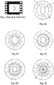
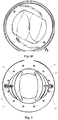
- Fig. 1 shows a conventional 35 mm film on which an object is imaged with a 2-fold horizontal compression factor - that is, using a 2-fold anamorphic lens - according to the prior art.
- the original object was a circle, which has now become an oval due to the 2-fold horizontal compression.
- Another 2-fold anamorphic lens is used for the subsequent projection in order to rectify the film image again and to obtain a widescreen image, as was already used by the CinemaScope system described above in the 1950s.
- the objects and people are in focus when projected Corrected again as desired, but alienation remains in the unsharp area.
- the oval on the film becomes a circle again when it is in the focus area, whereas the oval does not completely become a circle again when it is in the out-of-focus area - the object depicted is one People, it appears slimmer when it is out of focus.
- this side effect initially accepted in widescreen films, quickly developed into a desired visual aesthetic.
- the inventors of the present invention have now surprisingly found that this effect can also be achieved by providing a conventional spherical lens with an elliptical diaphragm, the longitudinal axis of which runs vertically, instead of with the anamorphic lenses (which are disadvantageous in terms of application and appearance in other respects).
- the term "elliptical” is intended to encompass both pure ellipses and all shapes that are elongated and have curved components - accordingly, the terms “major axis” and “minor axis” known from ellipses are transferred accordingly to these shapes by using "major axis" the long axis and “minor axis” the short axis of the elliptical shape.
- the compression factor of the anamorhopten - which, as explained above, is responsible for the visual aesthetic effect - corresponds to the ratio between its major and minor axis when applied to an ellipse and can thus also be translated to ellipse-like shapes in the above sense (a real compression of the recorded Image as with the anamorphic does not take place). Since, as mentioned at the beginning, a compression factor of 2 has proven to be optimal for the aesthetic image effect, this corresponds to a ratio between major and minor axes of 2: 1 for an elliptical opening.
- a conventional iris diaphragm consists of a stationary base body into which several lamellae, in particular circular lamellae, are inserted.
- Each of the circular lamellae has a crescent-shaped contour and has cylinder pins on its top and bottom, which are located at opposite ends of the circular lamella.
- One of the pins is inserted into the base body so that the circular lamella can rotate around this pin, the other pin is guided in the groove of a rotating ring, the number of grooves in the rotating ring corresponding to the number of circular lamellae.
- the circular lamellae are each rotated around their pin located in the base body and perform a pivoting movement towards or away from each other through the pin guided in the groove of the rotating ring, which leads to a closing or opening of the opening defined by the circular lamellae - this corresponds to fading out or fading in the iris diaphragm.
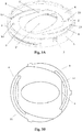
- the elliptical diaphragm according to the invention comprises such a conventional iris diaphragm which is provided with an additional immovable disc 1 with a fixed elliptical opening 2, the main axis of which runs vertically.
- the disk can be arranged in the z-direction (that is, in the direction of the optical axis) in front of or behind the iris diaphragm.
- Figures 2A-2E show an example of this arrangement, with the iris diaphragm being increasingly dimmed:
- the iris diaphragm is fully open, as a result of which the elliptical opening 2 of the disc 1 comes into full effect, since the main axis of the ellipse is smaller than or equal to the diameter of the fully open iris diaphragm.
- the iris diaphragm increasingly covers the elliptical opening 2 of the disk 1 until finally the diameter of the iris diaphragm, which is further masked out, is exactly as large as the minor axis of the ellipse ( Figure 2D ) or even smaller ( Figure 2E ).
- this can be a desired effect, because when stopping down the depth of field of an optical system increases, which in turn reduces the area of blur - which is characterized by the aesthetic image effect of the anamorphic lenses discussed above.
- This can now be compensated for by reducing the anamorphic factor, ie the compression factor in the horizontal direction.
- the horizontal compression and stretching is achieved by means of the anamorphic lenses with cylindrical lenses that have orthogonally different focal lengths and lead to a wide-angle effect horizontally in the x-direction, whereby the depth of field of the overall optical system (in the z-direction) is horizontal in the x- Direction is increased.
- the size ratio between the elliptical opening 2 of the disk 1 and the iris diaphragm can also be different from that in FIG Figures 2A-2E shown.
- the elliptical opening 2 can be larger, for example, so that right from the start (ie with the iris diaphragm fully open) there is no purely elliptical light passage is available.
- the iris diaphragm can also be dispensed with entirely if stopping down (e.g. due to the lighting conditions) is not of great importance and the purely elliptical shape is always desired.
- the opening 2 of the disk 1 does not have to be purely elliptical, but can be generally elliptical.
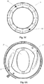
- FIG. 3A-E and 4A-F A second embodiment of the bezel is shown in Figures 3A-E and 4A-F shown.
- an iris diaphragm is provided, which is supplemented by further diaphragm elements.
- an immovable rear part 3 in the form of a disk which has an opening in the middle and two guides 4 (e.g. in the form of edges) and is fixed to the Base body 5 is connected to the iris diaphragm (see Figures 3A and 3B ).
- a closing ring 6 is provided, which likewise has an opening 7 and two curved grooves 8 (see Fig. Figure 3A and 3D ) and, in contrast to the rear part 3, is rotatable:
- the rotating ring 9 of the iris diaphragm has two pegs 10, which extend through a respective groove 11 in the rear part 3 into two bores 12 in the end ring 6 (see Fig. Figure 3A and 3E ) - If the rotating ring 9 is now rotated, the closing ring 6 also rotates.
- the stopping down of the iris diaphragm thus simultaneously leads to a stopping down of the linear diaphragm defined by the lamellae 1 '.
- the two slats 1 ' can be moved at their radially outer edges in the respective guide 4 of the rear part 3 or they can each have a projection on the side facing the rear part 3, which moves in the respective guide 4 of the rear part 3, whereby the Slats 1 'are additionally supported in their linear movement.
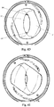
- Figure 4B shows the first stage of dimming, where the iris diaphragm is still not used, but the opening 2 'of the linear diaphragm has points at the upper and lower end due to the sliding of the two blades 1' against each other and is therefore no longer completely elliptical, but generally elliptical is.
- Figure 4D The iris diaphragm comes into play for the first time and "rounds off” the tips of the elliptical opening 2 'of the linear diaphragm, which is also further closed, somewhat (due to the progressive sliding of the two lamellae 1' against each other more and more pronounced). This "rounding off” the upper and lower tips of the opening 2 'of the linear diaphragm through the iris diaphragm, which also closes further, then becomes more pronounced during further stopping down according to FIG. Figures 4D-4F away.
- This narrowing of the light transmission when stopping down is contrary to the stopping behavior of the first embodiment and may also be desirable in certain cases, e.g. if it is less about the quantity of the aesthetic effect (i.e. the expansion of the area of blurring caused by the anamorphic aesthetic effect discussed above is more about its quality:
- the depth of field of an optical system increases when stopping down, which in turn reduces the unsharp area, which can be compensated by the fact that the anamorphic factor, i.e.
- the compression factor in the horizontal direction is reduced (which in turn is at the expense of the visual aesthetic effect itself) - on the other hand, if the visual aesthetic effect itself is to be increased, the compression factor must be increased in the horizontal direction (which again at the expense of the expansion or qua of the aesthetic effect).
- the linear movement of the lamellae 1 ' can also be effected in a different way than by coupling the rotary ring 9 to the end ring 6 and the pins 13 of the lamellae 1 'guided in the grooves 8 of the end ring 6 - essential for implementing the basic idea is only the linear movement of the lamellae 1' so that the main axis of the elliptical opening 2 'does not change its orientation.
- the importance of maintaining the axis orientation of the elliptical opening has already been discussed in connection with the first embodiment.
- the rear part 3 is also not an essential component for the implementation of the basic idea, but merely a constructive measure to give the movable slats 1 'additional stability - on the other hand, if the greatest possible stability for the slats 1' is desired, the opening in the rear part 3 of the largest elliptical opening 2 'between the lamellas 1' (as in Figure 3B shown) in order to achieve the largest possible contact surface.
- the size ratio between the elliptical opening 2 'of the linear diaphragm defined by the two lamellae 1' at the beginning and the iris diaphragm can be different from that in FIG Figures 4A-4F shown.
- the elliptical opening 2 ' can be smaller, for example, so that the "rounding off" of the upper and lower tips of the light passage of the linear diaphragm only occurs when stopping down further, or conversely larger, so that when stopping down there are never peaks at the upper and lower ends of the light passage .
- the opening 2 of the disk 1 does not have to be purely elliptical at the beginning, but can be generally elliptical.
- the iris diaphragm can also be completely dispensed with, in which case the rotary ring 9 is only used to rotate the closing ring 3 or the closing ring is rotated directly via suitable gripping elements and the dimming takes place only by the linear displacement of the lamellae 1 '.
- FIG. 5 and 6A-F A third embodiment of the bezel is shown in FIG Fig. 5 and 6A-F shown.
- one is Iris diaphragm provided, which is supplemented by further diaphragm elements.
- Fig. 5 it can be seen that, in addition to the circular lamellae 14 on the left and right side of the base body 5 of the iris diaphragm, a further lamella 1 ′′ is secured and biased towards the outer circumference of the base body 5, for example by springs 15, while the lamellae 1 ′′ in the direction of the center are connected to the circular lamellae 14 of the iris diaphragm, for example, by a clamp encompassing the respective circular lamella (s) 14.
- Another type of fastening and entrainment of the lamellae 1 can be to secure them via pins and grooves or bores on several circular lamellae 14 of the iris diaphragm. Between them, the lamellae 1" define the long sides of an elliptical opening 2 "on the right and left upper and lower boundaries are defined by the circular lamellae 14 of the iris diaphragm. The contour of the lamellae 1 ′′ towards the center can be concave or also straight. If the iris diaphragm is closed, the lamellae 1 ′′ move linearly inwards in the horizontal direction (and thus perpendicular to the main axis of the elliptical opening). defined linear diaphragm by moving them linearly towards each other.
- the second embodiment there is a narrow elliptical light passage, which on the right and left sides through the inner contour of the lamellas 1 "of the linear diaphragm opening 2" and on the upper and lower sides lower ends is characterized by the curvature of the iris diaphragm.
- This narrowing of the light passage when stopping down may, as already explained in connection with the second embodiment, be desirable in certain applications, e.g. if it is less a question of the quantity of the aesthetic image effect (i.e. the expansion of the blurring area, which is characterized by the anamorphic image aesthetic effect discussed above) than its quality.
- the linear movement of the lamellae 1 can also be effected in a different way than by coupling them to the outer sides of the base body 5 and to the circular lamellae 14 of the iris diaphragm - the only essential factor in implementing the basic idea is the linear movement of the lamellae 1", so that the main axis of the elliptical Opening 2 "does not change its orientation.
- the importance of maintaining the axial orientation of the elliptical opening has already been discussed in connection with the first embodiment.
- the size ratio between the elliptical opening 2 "defined by the two lamellae 1" of the linear diaphragm and the iris diaphragm can be different from that in FIG Figures 6A-6F shown.
- the iris diaphragm can again be completely dispensed with, in which case the upper areas of the elliptical opening 2" are not blocked by the circular lamellae 13 of the iris diaphragm, but are formed by a disk with a fixed round opening and the dimming is done only by the linear displacement of the lamellas 1 ", which in turn by a suitable device that For example, the closing ring 6 of the second embodiment with its curved grooves 8 can resemble, can be held and moved.
- the optical aberrations of the anamorphic lenses are eliminated, i.e. the barrel-shaped geometric distortion, which leads to annoying curvatures of straight lines, especially with short focal lengths, as well as the aberrations that cause blurring in the image field in the upper and lower area as well as in the corners and on the side edges, which are disturbing when the aperture is fully open to make noticable.
- the present invention allows the use of sharper lenses with a higher light intensity and a larger close-up limit, and the image section does not change when focusing, as is the case with anamorphic lenses.
- the diaphragm allows much greater flexibility, since the compression effect can be varied depending on the embodiment via the shape of the elliptical diaphragm, which changes when stopping down, without the objective having to be changed (as with the anamorphic lens).
Description
Die vorliegende Erfindung betrifft eine ellipsenartige Blende für ein Foto- oder Filmkameraobjektiv bzw. für eine Foto- oder Filmkamera.The present invention relates to an elliptical diaphragm for a photo or film camera lens or for a photo or film camera.
Fotographische und Filmkameraobjektive sind in der Regel mit kreisförmigen Irisblenden ausgestattet, die aus mehreren Blendenlamellen bestehen und bei allen Blendenöffnungen eine annähernd kreisförmige Öffnung transversal zur Achse der Objektive aufweisen. Die Kreisförmigkeit über alle Blendenöffnungen ist wünschenswert, wenn der Qualität der aus sphärischen Linsen bestehenden Objektiven durch möglichst wenig Bildfehler im aufgezeichneten Bild Rechnung getragen werden soll.Photographic and film camera lenses are usually equipped with circular iris diaphragms, which consist of several diaphragm blades and at all diaphragm openings have an approximately circular opening transversely to the axis of the lenses. The circularity over all aperture openings is desirable if the quality of the objectives consisting of spherical lenses is to be taken into account with as few image errors as possible in the recorded image.
Andererseits mag es Anwendungen geben, wo im Gegenteil gerade eine Aberration oder Verfremdung des aufgezeichneten Bildes erzielt werden soll. Das kann z.B. durch Vorsätze oder durch die Konstruktion der Objektive selbst erfolgen. Im letzteren Fall kann ein Objektiv so konstruiert sein, dass es zu einer gewünschten Verzeichnung kommt (wie z.B. bei Fisheye-Objektiven), es kann aber auch der Fall sein, dass ein Objektiv aus ganz anderen Gründen eine Konstruktion aufweist, die als Nebeneffekt eine Verfremdung mit sich führt - das ist bei anamorphotischen Objektiven der Fall.On the other hand, there may be applications where, on the contrary, an aberration or alienation of the recorded image is to be achieved. This can be done, for example, through attachments or through the construction of the lenses themselves. In the latter case, a lens can be designed in such a way that the desired distortion occurs (as is the case with fisheye lenses, for example), but it can also be the case that a lens has a construction for completely different reasons that has a side effect of alienation with it - this is the case with anamorphic lenses.
Anamorphotische Objektive, auch kurz "Anamorphoten" genannt, sind in der Filmindustrie seit den 50er Jahren bekannt. Beeinflusst durch die damals stark voranschreitende Ausbreitung des Fernsehens, begann die Filmindustrie in dieser Zeit, Filme im Breitwandformat zu produzieren, um sich vom Fernsehen - nicht zuletzt in qualitativer Hinsicht - absetzen zu können. So führte z.B. die 20th Century Fox das CinemaScope-Verfahren ein, bei dem ein Anamorphot verwendet wird, um horizontal breitere Bilder aufzunehmen und sie zur Aufzeichnung auf das Filmmaterial horizontal zu stauchen, sodass sie auf den beim herkömmlichen Film verfügbaren Platz passen; das auf dem Film gestauchte Bild wird dann bei der Projektion unter Verwendung eines zweiten Anamorphoten wieder horizontal gestreckt, und das Endresultat ist ein auf die Kinoleinwand projiziertes Breitwandbild. Das anamorphotische Verfahren wird also verwendet, um bei Verwendung des herkömmlichen Filmformats dennoch ein breiteres Projektionsformat zu erreichen.Anamorphic lenses, also called "anamorphic lenses" for short, have been known in the film industry since the 1950s. Influenced by the rapid expansion of television at the time, the film industry began to produce films in widescreen format in order to set itself apart from television - not least in terms of quality. For example, introduced the 20 th Century Fox Cinemascope process in which an anamorphic lens is used to accommodate horizontally wider images and compress them for recording on the footage horizontally, so they fit on the available in the conventional film space; the image compressed on the film is then stretched horizontally again during projection using a second anamorphic lens, and the end result is a widescreen image projected onto the cinema screen. The anamorphic method is used to achieve a wider projection format when using the conventional film format.
Um dieses horizontale Stauchen und Strecken zu erreichen, umfassen die Anamorphoten zylindrische Linsen, die orthogonal unterschiedliche Brennweiten (z.B. horizontal 50 mm und vertikal 100 mm bei einem 2-fach Anamorphoten, d.h. einem Anamorphoten mit Stauchungsfaktor 2) erzeugen. Werden diese zylindrischen Linsen wie ein Vorsatz vor der sphärischen Optik positioniert, wirken sie wie ein Weitwinkelobjektiv und erhöhen daher die Schärfentiefe des optischen Gesamtsystems (also in z-Richtung), jedoch nur entlang einer der Transversalachsen des optischen Systems (bei horizontaler Stauchung horizontal in x-Richtung), während dieser Effekt entlang der anderen Transversalachse (bei horizontaler Stauchung vertikal in y-Richtung) nicht auftritt. Das führt zu einer bleibenden Verfremdung bzw. Abstraktion der unscharfen Bereiche des aufgezeichneten Bildes: Außerhalb der Schärfenebene entstehen ovale unscharfe Verläufe, die alle Details, die im Unschärfebereich liegen, beeinflussen, indem sie verzerrt als ovale Verläufe abgebildet werden (analoges gilt für die Spitzlichter, die nicht als helle kreisrunde Scheibchen abgebildet werden, sondern ebenfalls als ovale) - diese Verfremdung ist nicht vollständig rückgängig zu machen und bleibt auch bei Anwendung des zweiten horizontal wieder streckenden Anamorphoten zur Projektion bestehen. Während daher Gegenstände und Personen im Schärfebereich nach der Projektion (d.h. bei Anwendung des zweiten Anamorphoten) wie gewünscht wieder unverzerrt bzw. unverfremdet dargestellt werden, erscheinen sie im Unschärfebereich schlanker, da der Unschärfebereich die bereits erwähnte bleibende Abstraktion aufweist. (In diesem Zusammenhang ist noch anzumerken, dass die zylindrischen Linsen auch hinter der sphärischen Optik positioniert werden können, jedoch unter Aufgabe des oben erwähnten Effekts.) Die Stärke dieses Effekts hängt vom Stauchungsfaktor, d.h. vom Verhältnis der beiden Brennweiten des Anamorphoten ab: je unterschiedlicher die Brennweiten und damit der Stauchungsfaktor, umso stärker der Effekt.In order to achieve this horizontal compression and stretching, the anamorphic lenses include cylindrical lenses that produce orthogonally different focal lengths (for example, horizontally 50 mm and vertically 100 mm for a double anamorphic lens, ie an anamorphic lens with a compression factor of 2). If these cylindrical lenses are positioned like an attachment in front of the spherical optics, they act like a wide-angle lens and therefore increase the depth of field of the overall optical system (i.e. in the z-direction), but only along one of the transverse axes of the optical system (with horizontal compression, horizontal in x -Direction), while this effect does not occur along the other transversal axis (with horizontal compression vertically in the y-direction). This leads to a permanent alienation or abstraction of the fuzzy areas of the recorded image: Outside the focal plane, oval fuzzy gradients arise, which influence all details that are in the out of focus area by being depicted as distorted oval gradients (the same applies to the highlights, which are not as bright, circular discs are shown, but also as oval) - this alienation cannot be completely reversed and remains even when the second horizontally stretching anamorphic lens is used for projection. Therefore, while objects and people in the focus area after the projection (ie when using the second anamorphic lens) are again displayed undistorted or alienated as desired, they appear slimmer in the unsharp area because the unsharp area has the abovementioned permanent abstraction. (In this context it should also be noted that the cylindrical lenses can also be positioned behind the spherical optics, but with the abandonment of the above-mentioned effect.) The strength of this effect depends on the compression factor, i.e. the ratio of the two focal lengths of the anamorphic lens: the more different the focal lengths and thus the compression factor, the stronger the effect.
Diese Verfremdung bzw. Abstraktion der unscharfen Bereiche war zunächst ein bei Breitwandfilmen in Kauf genommener Nebeneffekt, der sich jedoch schnell zu einer durchaus gewünschten Bildästhetik entwickelt hat, die im Laufe der letzten Jahrzehnte geradezu Kultstatus erlangt hat. So werden schon seit längerem Anamorphoten für Filmaufnahmen eingesetzt, nur um diesen Effekt zu erzeugen, wobei sich ein Stauchungsfaktor von 2 bisher als optimal für den bildästhetischen Effekt erwiesen hat.This alienation or abstraction of the blurred areas was initially a side effect that was accepted in widescreen films, but it quickly developed into a desired visual aesthetic that has achieved cult status over the last few decades. Anamorphic lenses have been used for film recordings for a long time just to create this effect, whereby a compression factor of 2 has so far proven to be optimal for the aesthetic effect.
Anamorphoten weisen jedoch auch unerwünschte Nachteile auf. Wenn die zylindrischen Linsen vor der aufnehmenden sphärischen Optik positioniert sind, um den oben erläuterten bildästhetischen Effekt zu erzeugen, führen die zylindrischen Linsen der Anamorphoten zu einer tonnenförmigen geometrischen Verzeichnung, die insbesondere bei kurzen Brennweiten zu durchaus störenden Krümmungen gerader Linien führt. Darüberhinaus ergeben sich Aberrationen, d.h. im Bildfeld entstehen im oberen und unteren Bereich sowie in den Ecken und an den seitlichen Rändern Unschärfen, die sich bei voll geöffneter Blende störend bemerkbar machen. Des weiteren haben Anamorphoten eine beschränkte Naheinstellgrenze und eine geringere Lichtstärke. Darüberhinaus ändert sich der Bildausschnitt beim Fokussieren und es werden bei digitaler Aufzeichnung angepasste Sensoren benötigt, die dem gestauchten Bildausschnit entsprechen. Schließlich sind Anamorphoten in der Regel aufwendiger in der Herstellung und dasurch weniger robust sowie aufgrund ihrer größeren Bauform und ihres größeren Gewichts unbequemer in der Handhabung.However, anamorphic lenses also have undesirable disadvantages. If the cylindrical lenses are positioned in front of the receiving spherical optics in order to produce the image-aesthetic effect explained above, the cylindrical lenses of the anamorphic lenses lead to barrel-shaped geometric distortion, which leads to disturbing curvatures of straight lines, especially with short focal lengths. In addition, there are aberrations, ie in the image field in the upper and lower areas as well as in the corners and on the side edges, blurring is noticeable when the aperture is fully open. Furthermore have Anamorphic a limited focus limit and a lower light intensity. In addition, the image section changes when you focus and digital recording requires adapted sensors that correspond to the compressed image section. Finally, anamorphic lenses are generally more complex to manufacture and therefore less robust and, due to their larger design and greater weight, are more uncomfortable to handle.
Es besteht also ein Bedarf an der Verwirklichung der oben beschriebenen Bildästhetik der Anamorphoten, d.h. deren Verfremdung bzw. Abstraktion der unscharfen Bereiche des aufgezeichneten Bildes, jedoch ohne die Nachteile dieser Objektive in Kauf nehmen zu müssen.There is thus a need to realize the anamorphic image aesthetics described above, i. their alienation or abstraction of the blurred areas of the recorded image, but without having to accept the disadvantages of these lenses.
Es ist daher ein Ziel der vorliegenden Erfindung, ein optisches System für die Filmindustrie vorzusehen, das bei Beibehaltung der Bildästhetik der Anamorphoten, d.h. der Verfremdung bzw. Abstraktion der unscharfen Bereiche des aufgezeichneten Bildes, zu besserer Bildqualität führt sowie leichter herzustellen, einfacher in der Handhabung und flexibler in der Anwendung ist.It is therefore an object of the present invention to provide an optical system for the motion picture industry which, while maintaining the image aesthetics of the anamorphic, i. the alienation or abstraction of the blurred areas of the recorded image, leads to better image quality and is easier to produce, easier to use and more flexible to use.
Dies ist erfindungsgemäß erreicht worden mit einer Blende für ein Foto- oder Filmkameraobjektiv gemäß AnspruchThis has been achieved according to the invention with a screen for a photo or film camera lens according to claim
Andere vorteilhafte Merkmale der erfindungsgemässen Blende sind in dem Unteranspruch offenbart.Other advantageous features of the diaphragm according to the invention are disclosed in the dependent claim.
- Fig. 1Fig. 1
- zeigt ein mit einem anamorphotischen System nach dem Stand der Technik auf einen 35 mm Film abgebildetes ursprünglich rundes Objekt;Figure 13 shows an originally round object imaged on 35mm film with a prior art anamorphic system;
- Fig. 2A-EFigures 2A-E
- zeigen eine erste Ausführungsform der erfindungsgemäßen Blende bei unterschiedlichen Öffnungen der Irisblende;show a first embodiment of the diaphragm according to the invention with different openings of the iris diaphragm;
- Fig. 3AFigure 3A
- zeigt eine zweite nicht erfindungsgemäße Ausführungsform der Blende in einer Schrägansicht von oben;shows a second embodiment of the screen not according to the invention in an oblique view from above;
- Fig. 3BFigure 3B
-
zeigt das Rückteil der Blende aus
Fig. 3A ;shows the back of the panelFigure 3A ; - Fig. 3CFigure 3C
-
zeigt eine der beiden Lamellen des Linearblendenanteils der Blende aus
Fig. 3A ;shows one of the two lamellas of the linear diaphragm portion of the diaphragmFigure 3A ; - Fig. 3DFigure 3D
-
zeigt den Abschlussring der Blende aus
Fig. 3A ;shows the cover ring of the bezelFigure 3A ; - Fig. 3EFigure 3E
-
zeigt den Drehring der Blende aus
Fig. 3A ;shows the rotating ring of the bezelFigure 3A ; - Fig. 4A-FFigures 4A-F
- zeigen die Blende gemäß der zweiten Ausführungsform bei unterschiedlichen Öffnungen der Irisblende;show the diaphragm according to the second embodiment with different openings of the iris diaphragm;
- Fig. 5Fig. 5
- zeigt eine dritte nicht erfindungsgemäße Ausführungsform der Blende;shows a third embodiment of the screen not according to the invention;
- Fig. 6A-EFigures 6A-E
- zeigen die Blende gemäß der dritten Ausführungsform bei unterschiedlichen Öffnungen der Irisblende.show the diaphragm according to the third embodiment with different openings of the iris diaphragm.
Die Erfinder der vorliegenden Erfindung haben nun überraschenderweise herausgefunden, dass sich dieser Effekt anstelle mit den (anwendungstechnisch und optisch in anderer Hinsicht nachteiligen) Anamorphoten auch dadurch erzielen lässt, dass ein herkömmliches sphärisches Objektiv mit einer ellipsenartigen Blende versehen wird, deren Längsachse vertikal verläuft. Der Begriff "ellipsenartig" soll hier sowohl reine Ellipsen als auch alle solche Formen umfassen, die länglich sind und gekrümmte Bestandteile aufweisen - dementsprechend werden die von Ellipsen bekannten Begriffe "Hauptachse" und "Nebenachse" sinngemäß auf diese Formen übertragen, indem mit "Hauptachse" die lange Achse und mit "Nebenachse" die kurze Achse der ellipsenartigen Form bezeichnet wird. Der Stauchungsfaktor der Anamorhopten - der, wie eingangs erläutert, für den bildästhetischen Effekt verantwortlich ist - entspricht übertragen auf eine Ellipse dem Verhältnis zwischen deren Haupt- und Nebenachse und kann so auch sinngemäß auf ellipsenartige Formen im obigen Sinne übertragen werden (eine reale Stauchung des aufgezeichneten Bildes wie bei den Anamorphoten findet nicht statt). Da sich, wie eingangs erwähnt, ein Stauchungsfaktor von 2 als optimal für den bildästhetischen Effekt erwiesen hat, entspricht das bei einer ellipsenartigen Öffnung einem Verhältnis zwischen Haupt- und Nebenachse von 2 : 1.The inventors of the present invention have now surprisingly found that this effect can also be achieved by providing a conventional spherical lens with an elliptical diaphragm, the longitudinal axis of which runs vertically, instead of with the anamorphic lenses (which are disadvantageous in terms of application and appearance in other respects). The term "elliptical" is intended to encompass both pure ellipses and all shapes that are elongated and have curved components - accordingly, the terms "major axis" and "minor axis" known from ellipses are transferred accordingly to these shapes by using "major axis" the long axis and "minor axis" the short axis of the elliptical shape. The compression factor of the anamorhopten - which, as explained above, is responsible for the visual aesthetic effect - corresponds to the ratio between its major and minor axis when applied to an ellipse and can thus also be translated to ellipse-like shapes in the above sense (a real compression of the recorded Image as with the anamorphic does not take place). Since, as mentioned at the beginning, a compression factor of 2 has proven to be optimal for the aesthetic image effect, this corresponds to a ratio between major and minor axes of 2: 1 for an elliptical opening.
Eine gewöhnliche Irisblende nach dem Stand der Technik besteht aus einem stationären Grundkörper, in den mehrere Lamellen, insbesondere Kreislamellen, gesteckt werden. Jede der Kreislamellen hat eine sichelförmige Kontur und weist Zylinderzapfen auf ihrer Ober- und Unterseite auf, die sich an gegenüberliegenden Enden der Kreislamelle befinden. Einer der Zapfen wird in den Grundkörper gesteckt, damit die Kreislamelle eine Drehbewegung um diesen Zapfen ausführen kann, der andere Zapfen wird in der Nut eines Drehrings geführt, wobei die Anzahl der Nuten im Drehring der Anzahl der Kreislamellen entspricht. Je nach Richtung, in die der Drehring nun gedreht wird, werden die Kreislamellen jeweils um ihren im Grundkörper befindlichen Zapfen gedreht und vollführen durch den in der Nut des Drehrings geführten Zapfen eine Schwenkbewegung aufeinander zu oder voneinander weg, was zu einem Schließen bzw. Öffnen der von den Kreislamellen definierten Öffnung führt - das entspricht dem Abblenden bzw. Aufblenden der Irisblende.A conventional iris diaphragm according to the prior art consists of a stationary base body into which several lamellae, in particular circular lamellae, are inserted. Each of the circular lamellae has a crescent-shaped contour and has cylinder pins on its top and bottom, which are located at opposite ends of the circular lamella. One of the pins is inserted into the base body so that the circular lamella can rotate around this pin, the other pin is guided in the groove of a rotating ring, the number of grooves in the rotating ring corresponding to the number of circular lamellae. Depending on the direction in which the rotating ring is now rotated, the circular lamellae are each rotated around their pin located in the base body and perform a pivoting movement towards or away from each other through the pin guided in the groove of the rotating ring, which leads to a closing or opening of the opening defined by the circular lamellae - this corresponds to fading out or fading in the iris diaphragm.
In einer ersten Ausführungsform umfasst die erfindungsgemäße ellipsenartige Blende eine derartige herkömmliche Irisblende, die mit einer zusätzlichen unbeweglichen Scheibe 1 mit einer festen ellipsenförmigen Öffnung 2 versehen ist, deren Hauptachse vertikal verläuft. Die Scheibe kann in z-Richtung (also in Richtung der optischen Achse) vor oder hinter der Irisblende angeordnet sein.
Zu Beginn (d.h. bei offener oder nur gering abgeblendeter Irisblende) erhält man also einen vollständig ellipsenförmigen Lichtdurchlass (s.
Das Größenverhältnis zwischen der ellipsenförmigen Öffnung 2 der Scheibe 1 und der Irisblende kann auch ein anderes sein als in
Es ist für die Bildästhetik von größter Bedeutung, dass die ellipsenartige Öffnung 2 der Scheibe 1 - und damit natürlich auch deren Achsenausrichtung - stationär ist, denn der oben erwähnte "Verschlankungseffekt" im Unschärfebereich, insbesondere von Personen, wird nur auf diese Weise erreicht. Der gegenteilige Effekt, d.h. eine "Verdickung" von im Unschärfebereich befindlichen Personen, kann natürlich erreicht werden, wenn die Hauptachse der ellipsenartigen Öffnung 2 horizontal verläuft, was einer vertikalen Stauchung entspricht.It is of the greatest importance for the aesthetics of the image that the
Eine zweite Ausführungsform der Blende ist in
Durch diese Überlagerung der Kreislamellen 14 der Irisblende und der Lamellen 1' der Linearblende erhält man, wie
Zu Beginn (d.h. bei offener Iris- und Linearblende) erhält man also einen vollständig ellipsenförmigen Lichtdurchlass (s.
Die Linearbewegung der Lamellen 1' kann auch auf andere Weise bewirkt werden als über die Kopplung des Drehrings 9 mit dem Abschlussring 6 und die in den Nuten 8 des Abschlussringes 6 geführten Zapfen 13 der Lamellen 1' - wesentlich zur Umsetzung des Grundgedankens ist lediglich die Linearbewegung der Lamellen 1', damit die Hauptachse der ellipsenartigen Öffnung 2' nicht ihre Orientierung ändert. Die Bedeutung der Beibehaltung der Achsenausrichtung der ellipsenartigen Öffnung ist bereits im Zusammenhang mit der ersten Ausführungsform erörtert worden. Auch das Rückteil 3 ist kein für die Umsetzung des Grundgedankens wesentlicher Bestandteil, sondern lediglich eine konstruktive Maßnahme, um den beweglichen Lamellen 1' zusätzliche Stabilität zu verleihen - ist andererseits eine größtmögliche Stabilität für die Lamellen 1' gewünscht, kann die Öffnung im Rückteil 3 der größten ellipsenförmigen Öffnung 2' zwischen den Lamellen 1' entsprechen (wie in
Wie bei der ersten Ausführungsform kann auch hier das Größenverhältnis zwischen der von den beiden Lamellen 1' zu Beginn definierten ellipsenförmigen Öffnung 2' der Linearblende und der Irisblende ein anderes sein als das in
Eine dritte Ausführungsform der Blende ist in
Durch diese Überlagerung der Kreislamellen 14 der Irisblende und der Lamellen 1" der Linearblende erhält man, wie
Am Ende (d.h. bei stark oder ganz abgeblendeter Iris- und Linearblende) ist also wie bei der zweiten Ausführungsform ein schmaler ellipsenartiger Lichtdurchlass vorhanden, der an den rechten und linken Seiten durch die Innenkontur der Lamellen 1" der Linearblendenöffnung 2" und an den oberen und unteren Enden durch die Krümmung der Irisblende geprägt ist. Dieses Schmalerwerden des Lichtdurchlasses beim Abblenden mag, wie bereits im Zusammenhang mit der zweiten Ausführungsform erläutert, in bestimmten Anwendungsfällen erwünscht sein, z.B. wenn es weniger um die Quantität des bildästhetischen Effekts (also um die Ausdehnung des Unschärfebereichs, der sich durch den oben erörterten bildästhetischen Effekt der Anamorphoten auszeichnet) als vielmehr um dessen Qualität geht.At the end (ie when the iris and linear diaphragm are heavily or completely dimmed), as in the second embodiment, there is a narrow elliptical light passage, which on the right and left sides through the inner contour of the
Die Linearbewegung der Lamellen 1" kann auch auf andere Weise bewirkt werden als über deren Kopplung an die Außenseiten des Grundkörpers 5 und an die Kreislamellen 14 der Irisblende - wesentlich zur Umsetzung des Grundgedankens ist lediglich die Linearbewegung der Lamellen 1", damit die Hauptachse der ellipsenartigen Öffnung 2" nicht ihre Orientierung ändert. Die Bedeutung der Beibehaltung der Achsenausrichtung der ellipsenartigen Öffnung ist bereits im Zusammenhang mit der ersten Ausführungsform erörtert worden.The linear movement of the
Wie bei der ersten und zweiten Ausführungsform kann auch hier das Größenverhältnis zwischen der von den beiden Lamellen 1" definierten ellipsenartigen Öffnung 2" der Linearblende und der Irisblende ein anderes sein als das in
Für alle oben beschriebenen Ausführungsformen gilt, dass sie die von den Anamorphoten bekannte Bildästhetik umsetzen, gegenüber den Anamorphoten jedoch deutliche Vorteile aufweisen. Zunächst entfallen die optischen Bildfehler der Anamorphoten, d.h. die tonnenförmige geometrische Verzeichnung, die insbesondere bei kurzen Brennweiten zu durchaus störenden Krümmungen gerader Linien führt, sowie die Aberrationen, durch die im Bildfeld im oberen und unteren Bereich sowie in den Ecken und an den seitlichen Rändern Unschärfen entstehen, die sich bei voll geöffneter Blende störend bemerkbar machen. Des weiteren erlaubt die vorliegende Erfindung den Einsatz schärferer Objektive mit höherer Lichtstärke und größerer Naheinstellgrenze, und der Bildausschnitt ändert sich nicht beim Fokussieren, wie es bei Anamorphoten der Fall ist. Weiterhin werden keine angepassten Sensoren, die dem durch den Anamorphoten gestauchten Bildausschnit entsprechen, benötigt, da keine reale Stauchung des aufgezeichneten Bildes stattfindet. Darüberhinaus wird die Unhandlichkeit der Anamorphoten (aufgrund von deren Größe und Gewicht) vermieden, da die erfindungsgemäße Blende mit herkömmlichen ausschliesslich aus sphärischen Linsen bestehenden Objektiven eingesetzt werden kann. Aus diesem Grund ist das gesamte optische System auch kostengünstiger, da die sphärischen Objektive bzw. deren Kamerasysteme einfach umgerüstet werden können unter Vermeidung des aufwendigen Herstellungsverfahrens der Anamorphoten, was auch zu deren geringerer Robustheit führt. Darüberhinaus erlaubt die Blende eine weitaus höhere Flexibilität, da der Stauchungseffekt je nach Ausführungsform über die sich beim Abblenden ändernde Form der ellipsenartigen Blende variiert werden kann, ohne dass (wie bei den Anamorphoten) das Objektiv gewechselt werden muss.It applies to all of the above-described embodiments that they implement the image aesthetics known from the anamorphic, but have clear advantages over the anamorphic. First of all, the optical aberrations of the anamorphic lenses are eliminated, i.e. the barrel-shaped geometric distortion, which leads to annoying curvatures of straight lines, especially with short focal lengths, as well as the aberrations that cause blurring in the image field in the upper and lower area as well as in the corners and on the side edges, which are disturbing when the aperture is fully open to make noticable. Furthermore, the present invention allows the use of sharper lenses with a higher light intensity and a larger close-up limit, and the image section does not change when focusing, as is the case with anamorphic lenses. Furthermore, no adapted sensors, which correspond to the image section compressed by the anamorphic lens, are required, since there is no real compression of the recorded image. In addition, the unwieldiness of the anamorphic lenses (due to their size and weight) is avoided, since the diaphragm according to the invention can be used with conventional lenses consisting exclusively of spherical lenses. For this reason, the entire optical system is also more cost-effective, since the spherical lenses or their camera systems can be easily converted while avoiding the complex manufacturing process for the anamorphic lenses, which also leads to their less robustness. In addition, the diaphragm allows much greater flexibility, since the compression effect can be varied depending on the embodiment via the shape of the elliptical diaphragm, which changes when stopping down, without the objective having to be changed (as with the anamorphic lens).
Claims (2)
- Aperture for a photographic or film camera lens or for a photographic or film camera, characterized in that the aperture has a device with a disc (1) defining a fixed ellipse-like opening (2) and an iris, wherein the major axis of the ellipse-like opening (2) is less than or equal to the diameter of the fully opened iris, so that the light transmission of the aperture upon stopping down develops from the initial elliptical shape (2) at full opening of the iris towards the circle shape defined by circular blades (14) of the iris.
- Aperture according to claim 1, characterized in that the major axis of the ellipse-like opening (2) is vertical.
Priority Applications (1)
| Application Number | Priority Date | Filing Date | Title |
|---|---|---|---|
| EP18153177.3A EP3339950B1 (en) | 2015-07-23 | 2016-07-01 | Ellipse-like diaphragm for a camera lens or for a photographic or film camera |
Applications Claiming Priority (2)
| Application Number | Priority Date | Filing Date | Title |
|---|---|---|---|
| DE102015111985.4A DE102015111985A1 (en) | 2015-07-23 | 2015-07-23 | Ellipse-like aperture for a camera lens or for a photo or film camera |
| PCT/EP2016/065511 WO2017012843A1 (en) | 2015-07-23 | 2016-07-01 | Ellipse-like aperture for a camera lens assembly orfor a photo or film camera |
Related Child Applications (2)
| Application Number | Title | Priority Date | Filing Date |
|---|---|---|---|
| EP18153177.3A Division-Into EP3339950B1 (en) | 2015-07-23 | 2016-07-01 | Ellipse-like diaphragm for a camera lens or for a photographic or film camera |
| EP18153177.3A Division EP3339950B1 (en) | 2015-07-23 | 2016-07-01 | Ellipse-like diaphragm for a camera lens or for a photographic or film camera |
Publications (2)
| Publication Number | Publication Date |
|---|---|
| EP3326031A1 EP3326031A1 (en) | 2018-05-30 |
| EP3326031B1 true EP3326031B1 (en) | 2020-09-30 |
Family
ID=56497719
Family Applications (2)
| Application Number | Title | Priority Date | Filing Date |
|---|---|---|---|
| EP18153177.3A Active EP3339950B1 (en) | 2015-07-23 | 2016-07-01 | Ellipse-like diaphragm for a camera lens or for a photographic or film camera |
| EP16741250.1A Active EP3326031B1 (en) | 2015-07-23 | 2016-07-01 | Ellipse-like aperture for a camera lens assembly or for a photo or film camera |
Family Applications Before (1)
| Application Number | Title | Priority Date | Filing Date |
|---|---|---|---|
| EP18153177.3A Active EP3339950B1 (en) | 2015-07-23 | 2016-07-01 | Ellipse-like diaphragm for a camera lens or for a photographic or film camera |
Country Status (9)
| Country | Link |
|---|---|
| US (1) | US10942420B2 (en) |
| EP (2) | EP3339950B1 (en) |
| JP (1) | JP2018521361A (en) |
| KR (1) | KR20180032577A (en) |
| CN (1) | CN107850819A (en) |
| DE (2) | DE102015111985A1 (en) |
| ES (2) | ES2835286T3 (en) |
| HK (2) | HK1255715A1 (en) |
| WO (1) | WO2017012843A1 (en) |
Families Citing this family (9)
| Publication number | Priority date | Publication date | Assignee | Title |
|---|---|---|---|---|
| USD881973S1 (en) | 2015-07-24 | 2020-04-21 | Canon Denshi Kabushiki Kaisha | Interchangeable lens for camera |
| EP3358818A1 (en) * | 2017-02-03 | 2018-08-08 | Autoliv Development AB | Camera module for a motor vehicle and stereoscopic arrangement of at least two camera modules |
| TWI702465B (en) * | 2018-04-03 | 2020-08-21 | 春虹光電股份有限公司 | Camera module with variable aperture |
| TWI659239B (en) * | 2018-11-14 | 2019-05-11 | 大立光電股份有限公司 | Imaging optical lens assembly, imaging apparatus and electronic device |
| CN112617587A (en) * | 2020-12-31 | 2021-04-09 | 珠海格力电器股份有限公司 | Fan housing structure, cooking utensil and control method of cooking utensil |
| FR3127300B1 (en) * | 2021-09-21 | 2023-12-15 | Thales Sa | Non-rotating elliptical iris diaphragm |
| FR3127299A1 (en) * | 2021-09-21 | 2023-03-24 | Thales | Predetermined shape iris diaphragm, without shape rotation |
| TWI815645B (en) * | 2022-08-26 | 2023-09-11 | 大立光電股份有限公司 | Variable aperture module, imaging lens module and electronic device |
| TWI828317B (en) * | 2022-09-16 | 2024-01-01 | 大立光電股份有限公司 | Imaging lens module, camera module and electronic device |
Family Cites Families (27)
| Publication number | Priority date | Publication date | Assignee | Title |
|---|---|---|---|---|
| US1302359A (en) * | 1918-07-15 | 1919-04-29 | Frank E Garbutt | Elliptic iris. |
| US1510597A (en) * | 1922-08-04 | 1924-10-07 | Ilex Optical Company | Photographic shutter |
| GB226344A (en) | 1923-11-14 | 1924-12-24 | Frank Walton Jameson | Process of manufacturing fuel briquettes |
| GB1094194A (en) | 1964-08-14 | 1967-12-06 | Marconi Co Ltd | Improvements in or relating to irises |
| US4047807A (en) * | 1974-12-26 | 1977-09-13 | Minolta Camera Kabushiki Kaisha | Diaphragm device |
| JPS5563518U (en) * | 1978-10-24 | 1980-04-30 | ||
| JPS5563518A (en) | 1978-11-06 | 1980-05-13 | Nippon Electric Co | Dc voltage dividing circuit |
| GB2164470B (en) * | 1984-09-14 | 1988-10-26 | Michael Rodney Browning | Iris device |
| JPH04269727A (en) | 1991-02-25 | 1992-09-25 | Minolta Camera Co Ltd | Camera |
| GB9201156D0 (en) * | 1992-01-20 | 1992-03-11 | British Broadcasting Corp | Television camera iris |
| US5594519A (en) * | 1994-12-05 | 1997-01-14 | Asahi Kogaku Kogyo Kabushiki Kaisha | Blade mechanism |
| JP3550963B2 (en) * | 1997-08-08 | 2004-08-04 | ミノルタ株式会社 | Camera aperture mechanism |
| US6538827B2 (en) * | 2000-03-09 | 2003-03-25 | Donnelly Corporation | Non-circular aperture stop |
| US6811331B2 (en) * | 2002-06-12 | 2004-11-02 | Olympus Corporation | Lens shutter system |
| JP4812389B2 (en) * | 2004-12-14 | 2011-11-09 | パナソニック株式会社 | Lens hood equipment |
| US20060245752A1 (en) * | 2005-04-27 | 2006-11-02 | Koji Kawaguchi | Diaphragm device, lens assembly including same and surveillance camera |
| JP2006317618A (en) * | 2005-05-11 | 2006-11-24 | Sony Corp | Lens stop mechanism, lens barrel and imaging apparatus |
| US8164813B1 (en) * | 2007-06-16 | 2012-04-24 | Opto-Knowledge Systems, Inc. | Non-circular continuous variable aperture or shutter for infrared cameras |
| JP5214319B2 (en) | 2008-04-30 | 2013-06-19 | オリンパスメディカルシステムズ株式会社 | Imaging device |
| JP4798178B2 (en) * | 2008-07-11 | 2011-10-19 | ソニー株式会社 | Lens barrel and imaging device |
| JP5134694B2 (en) * | 2008-08-04 | 2013-01-30 | キヤノン株式会社 | Image processing apparatus and image processing method |
| CN202057894U (en) * | 2011-05-13 | 2011-11-30 | 利达光电股份有限公司 | Elliptical diaphragm projecting lens |
| CN104035263A (en) * | 2013-03-08 | 2014-09-10 | Jvc建伍株式会社 | Light quantity adjusting device and imaging apparatus |
| WO2014136457A1 (en) * | 2013-03-08 | 2014-09-12 | キヤノン電子株式会社 | Light-amount adjustment apparatus, optical device, and imaging apparatus |
| KR20150005107A (en) * | 2013-07-04 | 2015-01-14 | 삼성전자주식회사 | , optical scanning unit employing the same, and electrophotography type image forming apparatus |
| US9188767B2 (en) * | 2013-11-04 | 2015-11-17 | Christie Digital Systems Usa, Inc. | Relay lens system for a high dynamic range projector |
| WO2016199899A1 (en) * | 2015-06-12 | 2016-12-15 | キヤノン電子株式会社 | Vane drive device and image capture device |
-
2015
- 2015-07-23 DE DE102015111985.4A patent/DE102015111985A1/en not_active Withdrawn
- 2015-07-23 DE DE202015009206.3U patent/DE202015009206U1/en active Active
-
2016
- 2016-07-01 JP JP2018503254A patent/JP2018521361A/en not_active Abandoned
- 2016-07-01 ES ES18153177T patent/ES2835286T3/en active Active
- 2016-07-01 EP EP18153177.3A patent/EP3339950B1/en active Active
- 2016-07-01 EP EP16741250.1A patent/EP3326031B1/en active Active
- 2016-07-01 ES ES16741250T patent/ES2822572T3/en active Active
- 2016-07-01 KR KR1020187002577A patent/KR20180032577A/en unknown
- 2016-07-01 WO PCT/EP2016/065511 patent/WO2017012843A1/en active Application Filing
- 2016-07-01 CN CN201680043151.2A patent/CN107850819A/en active Pending
- 2016-07-01 US US15/746,362 patent/US10942420B2/en active Active
-
2018
- 2018-11-21 HK HK18114866.2A patent/HK1255715A1/en unknown
- 2018-11-21 HK HK18114867.1A patent/HK1255716A1/en unknown
Non-Patent Citations (1)
| Title |
|---|
| None * |
Also Published As
| Publication number | Publication date |
|---|---|
| CN107850819A (en) | 2018-03-27 |
| WO2017012843A1 (en) | 2017-01-26 |
| EP3326031A1 (en) | 2018-05-30 |
| KR20180032577A (en) | 2018-03-30 |
| JP2018521361A (en) | 2018-08-02 |
| US20180210314A1 (en) | 2018-07-26 |
| ES2835286T3 (en) | 2021-06-22 |
| HK1255715A1 (en) | 2019-08-23 |
| US10942420B2 (en) | 2021-03-09 |
| DE102015111985A1 (en) | 2017-01-26 |
| HK1255716A1 (en) | 2019-08-23 |
| ES2822572T3 (en) | 2021-05-04 |
| DE202015009206U1 (en) | 2016-11-21 |
| EP3339950A1 (en) | 2018-06-27 |
| EP3339950B1 (en) | 2020-10-21 |
Similar Documents
| Publication | Publication Date | Title |
|---|---|---|
| EP3326031B1 (en) | Ellipse-like aperture for a camera lens assembly or for a photo or film camera | |
| DE2657968A1 (en) | SOFT LENS SYSTEM | |
| DE19609727A1 (en) | Frame for stereoscopic images | |
| DE3932262C2 (en) | Flash setting device for a photographic camera with a zoom lens | |
| DE3202000A1 (en) | OPTICAL GRID FOR CORRECTING OPTICAL ERRORS | |
| DE2855496C2 (en) | Device for moving and / or tilting the lens of a reflex camera | |
| DE3531983A1 (en) | Iris bezel | |
| DE6601367U (en) | PHOTOGRAPHIC CAMERA WITH A CHANGEABLE LENS FOCAL LENGTH AND A CHANGEABLE FOCUS | |
| DE4204468C2 (en) | Camera with parallax and diopter correction | |
| DE2715780C3 (en) | Adjustment device for varifocal lenses | |
| DE2224429C3 (en) | ||
| DE602006000718T2 (en) | Lens device with a light aperture | |
| DE102005053277A1 (en) | Vario lens barrel with a rotatable cam ring | |
| DE10215140B4 (en) | Lens for a movie camera | |
| DE1572823B2 (en) | OPTICAL APERTURE | |
| EP3098639A1 (en) | Lens for variable adjustment of aberrations | |
| DE102015110441B3 (en) | Photographic lens, in particular portrait lens | |
| DE2713076A1 (en) | Low diffraction iris diaphragm for camera objective - has aperture further reduced below min. width by linearly varying, low density optical filters introduced over aperture | |
| DE653345C (en) | Adjustable lens aperture | |
| DE10025593A1 (en) | Set up of distance between object lenses of stereo camera for close-up photography to provide natural impression of distance when viewing images in stereo image frame | |
| DE2519991A1 (en) | PROJECTION SYSTEM | |
| DE1422574C (en) | Disc-shaped panoramic lens | |
| DE1422574A1 (en) | Wide angle optical system | |
| DE4134924C1 (en) | Reversible lens attachment increasing or reducing field of view - has coupling piece at either end and produces anamorphic effect for image taking or projecting | |
| DE4042546C2 (en) | Watertight and/or water-protected camera |
Legal Events
| Date | Code | Title | Description |
|---|---|---|---|
| STAA | Information on the status of an ep patent application or granted ep patent |
Free format text: STATUS: THE INTERNATIONAL PUBLICATION HAS BEEN MADE |
|
| PUAI | Public reference made under article 153(3) epc to a published international application that has entered the european phase |
Free format text: ORIGINAL CODE: 0009012 |
|
| STAA | Information on the status of an ep patent application or granted ep patent |
Free format text: STATUS: REQUEST FOR EXAMINATION WAS MADE |
|
| 17P | Request for examination filed |
Effective date: 20171212 |
|
| AK | Designated contracting states |
Kind code of ref document: A1 Designated state(s): AL AT BE BG CH CY CZ DE DK EE ES FI FR GB GR HR HU IE IS IT LI LT LU LV MC MK MT NL NO PL PT RO RS SE SI SK SM TR |
|
| AX | Request for extension of the european patent |
Extension state: BA ME |
|
| RIN1 | Information on inventor provided before grant (corrected) |
Inventor name: PRZYBYLLA, ALEXANDER Inventor name: MAERTIN, PETER |
|
| DAV | Request for validation of the european patent (deleted) | ||
| DAX | Request for extension of the european patent (deleted) | ||
| REG | Reference to a national code |
Ref country code: HK Ref legal event code: DE Ref document number: 1255716 Country of ref document: HK |
|
| REG | Reference to a national code |
Ref country code: DE Ref legal event code: R079 Ref document number: 502016011327 Country of ref document: DE Free format text: PREVIOUS MAIN CLASS: G03B0009040000 Ipc: G03B0009020000 |
|
| RIC1 | Information provided on ipc code assigned before grant |
Ipc: G03B 9/06 20060101ALI20200303BHEP Ipc: G02B 5/00 20060101ALI20200303BHEP Ipc: G03B 9/02 20060101AFI20200303BHEP |
|
| GRAP | Despatch of communication of intention to grant a patent |
Free format text: ORIGINAL CODE: EPIDOSNIGR1 |
|
| STAA | Information on the status of an ep patent application or granted ep patent |
Free format text: STATUS: GRANT OF PATENT IS INTENDED |
|
| INTG | Intention to grant announced |
Effective date: 20200417 |
|
| GRAS | Grant fee paid |
Free format text: ORIGINAL CODE: EPIDOSNIGR3 |
|
| GRAA | (expected) grant |
Free format text: ORIGINAL CODE: 0009210 |
|
| STAA | Information on the status of an ep patent application or granted ep patent |
Free format text: STATUS: THE PATENT HAS BEEN GRANTED |
|
| AK | Designated contracting states |
Kind code of ref document: B1 Designated state(s): AL AT BE BG CH CY CZ DE DK EE ES FI FR GB GR HR HU IE IS IT LI LT LU LV MC MK MT NL NO PL PT RO RS SE SI SK SM TR |
|
| REG | Reference to a national code |
Ref country code: CH Ref legal event code: EP Ref country code: GB Ref legal event code: FG4D Free format text: NOT ENGLISH |
|
| REG | Reference to a national code |
Ref country code: DE Ref legal event code: R096 Ref document number: 502016011327 Country of ref document: DE Ref country code: AT Ref legal event code: REF Ref document number: 1319420 Country of ref document: AT Kind code of ref document: T Effective date: 20201015 |
|
| REG | Reference to a national code |
Ref country code: IE Ref legal event code: FG4D Free format text: LANGUAGE OF EP DOCUMENT: GERMAN |
|
| PG25 | Lapsed in a contracting state [announced via postgrant information from national office to epo] |
Ref country code: BG Free format text: LAPSE BECAUSE OF FAILURE TO SUBMIT A TRANSLATION OF THE DESCRIPTION OR TO PAY THE FEE WITHIN THE PRESCRIBED TIME-LIMIT Effective date: 20201230 Ref country code: HR Free format text: LAPSE BECAUSE OF FAILURE TO SUBMIT A TRANSLATION OF THE DESCRIPTION OR TO PAY THE FEE WITHIN THE PRESCRIBED TIME-LIMIT Effective date: 20200930 Ref country code: NO Free format text: LAPSE BECAUSE OF FAILURE TO SUBMIT A TRANSLATION OF THE DESCRIPTION OR TO PAY THE FEE WITHIN THE PRESCRIBED TIME-LIMIT Effective date: 20201230 Ref country code: GR Free format text: LAPSE BECAUSE OF FAILURE TO SUBMIT A TRANSLATION OF THE DESCRIPTION OR TO PAY THE FEE WITHIN THE PRESCRIBED TIME-LIMIT Effective date: 20201231 Ref country code: FI Free format text: LAPSE BECAUSE OF FAILURE TO SUBMIT A TRANSLATION OF THE DESCRIPTION OR TO PAY THE FEE WITHIN THE PRESCRIBED TIME-LIMIT Effective date: 20200930 Ref country code: SE Free format text: LAPSE BECAUSE OF FAILURE TO SUBMIT A TRANSLATION OF THE DESCRIPTION OR TO PAY THE FEE WITHIN THE PRESCRIBED TIME-LIMIT Effective date: 20200930 |
|
| PG25 | Lapsed in a contracting state [announced via postgrant information from national office to epo] |
Ref country code: LV Free format text: LAPSE BECAUSE OF FAILURE TO SUBMIT A TRANSLATION OF THE DESCRIPTION OR TO PAY THE FEE WITHIN THE PRESCRIBED TIME-LIMIT Effective date: 20200930 Ref country code: RS Free format text: LAPSE BECAUSE OF FAILURE TO SUBMIT A TRANSLATION OF THE DESCRIPTION OR TO PAY THE FEE WITHIN THE PRESCRIBED TIME-LIMIT Effective date: 20200930 |
|
| REG | Reference to a national code |
Ref country code: NL Ref legal event code: MP Effective date: 20200930 |
|
| REG | Reference to a national code |
Ref country code: LT Ref legal event code: MG4D |
|
| PG25 | Lapsed in a contracting state [announced via postgrant information from national office to epo] |
Ref country code: EE Free format text: LAPSE BECAUSE OF FAILURE TO SUBMIT A TRANSLATION OF THE DESCRIPTION OR TO PAY THE FEE WITHIN THE PRESCRIBED TIME-LIMIT Effective date: 20200930 Ref country code: CZ Free format text: LAPSE BECAUSE OF FAILURE TO SUBMIT A TRANSLATION OF THE DESCRIPTION OR TO PAY THE FEE WITHIN THE PRESCRIBED TIME-LIMIT Effective date: 20200930 Ref country code: SM Free format text: LAPSE BECAUSE OF FAILURE TO SUBMIT A TRANSLATION OF THE DESCRIPTION OR TO PAY THE FEE WITHIN THE PRESCRIBED TIME-LIMIT Effective date: 20200930 Ref country code: PT Free format text: LAPSE BECAUSE OF FAILURE TO SUBMIT A TRANSLATION OF THE DESCRIPTION OR TO PAY THE FEE WITHIN THE PRESCRIBED TIME-LIMIT Effective date: 20210201 Ref country code: RO Free format text: LAPSE BECAUSE OF FAILURE TO SUBMIT A TRANSLATION OF THE DESCRIPTION OR TO PAY THE FEE WITHIN THE PRESCRIBED TIME-LIMIT Effective date: 20200930 Ref country code: LT Free format text: LAPSE BECAUSE OF FAILURE TO SUBMIT A TRANSLATION OF THE DESCRIPTION OR TO PAY THE FEE WITHIN THE PRESCRIBED TIME-LIMIT Effective date: 20200930 |
|
| REG | Reference to a national code |
Ref country code: ES Ref legal event code: FG2A Ref document number: 2822572 Country of ref document: ES Kind code of ref document: T3 Effective date: 20210504 |
|
| PG25 | Lapsed in a contracting state [announced via postgrant information from national office to epo] |
Ref country code: AL Free format text: LAPSE BECAUSE OF FAILURE TO SUBMIT A TRANSLATION OF THE DESCRIPTION OR TO PAY THE FEE WITHIN THE PRESCRIBED TIME-LIMIT Effective date: 20200930 Ref country code: IS Free format text: LAPSE BECAUSE OF FAILURE TO SUBMIT A TRANSLATION OF THE DESCRIPTION OR TO PAY THE FEE WITHIN THE PRESCRIBED TIME-LIMIT Effective date: 20210130 Ref country code: PL Free format text: LAPSE BECAUSE OF FAILURE TO SUBMIT A TRANSLATION OF THE DESCRIPTION OR TO PAY THE FEE WITHIN THE PRESCRIBED TIME-LIMIT Effective date: 20200930 |
|
| PG25 | Lapsed in a contracting state [announced via postgrant information from national office to epo] |
Ref country code: SK Free format text: LAPSE BECAUSE OF FAILURE TO SUBMIT A TRANSLATION OF THE DESCRIPTION OR TO PAY THE FEE WITHIN THE PRESCRIBED TIME-LIMIT Effective date: 20200930 Ref country code: NL Free format text: LAPSE BECAUSE OF FAILURE TO SUBMIT A TRANSLATION OF THE DESCRIPTION OR TO PAY THE FEE WITHIN THE PRESCRIBED TIME-LIMIT Effective date: 20200930 |
|
| REG | Reference to a national code |
Ref country code: DE Ref legal event code: R097 Ref document number: 502016011327 Country of ref document: DE |
|
| PLBE | No opposition filed within time limit |
Free format text: ORIGINAL CODE: 0009261 |
|
| STAA | Information on the status of an ep patent application or granted ep patent |
Free format text: STATUS: NO OPPOSITION FILED WITHIN TIME LIMIT |
|
| PG25 | Lapsed in a contracting state [announced via postgrant information from national office to epo] |
Ref country code: DK Free format text: LAPSE BECAUSE OF FAILURE TO SUBMIT A TRANSLATION OF THE DESCRIPTION OR TO PAY THE FEE WITHIN THE PRESCRIBED TIME-LIMIT Effective date: 20200930 |
|
| 26N | No opposition filed |
Effective date: 20210701 |
|
| PG25 | Lapsed in a contracting state [announced via postgrant information from national office to epo] |
Ref country code: SI Free format text: LAPSE BECAUSE OF FAILURE TO SUBMIT A TRANSLATION OF THE DESCRIPTION OR TO PAY THE FEE WITHIN THE PRESCRIBED TIME-LIMIT Effective date: 20200930 |
|
| REG | Reference to a national code |
Ref country code: CH Ref legal event code: PL |
|
| PG25 | Lapsed in a contracting state [announced via postgrant information from national office to epo] |
Ref country code: MC Free format text: LAPSE BECAUSE OF FAILURE TO SUBMIT A TRANSLATION OF THE DESCRIPTION OR TO PAY THE FEE WITHIN THE PRESCRIBED TIME-LIMIT Effective date: 20200930 |
|
| REG | Reference to a national code |
Ref country code: BE Ref legal event code: MM Effective date: 20210731 |
|
| PG25 | Lapsed in a contracting state [announced via postgrant information from national office to epo] |
Ref country code: LI Free format text: LAPSE BECAUSE OF NON-PAYMENT OF DUE FEES Effective date: 20210731 Ref country code: CH Free format text: LAPSE BECAUSE OF NON-PAYMENT OF DUE FEES Effective date: 20210731 |
|
| PG25 | Lapsed in a contracting state [announced via postgrant information from national office to epo] |
Ref country code: IS Free format text: LAPSE BECAUSE OF FAILURE TO SUBMIT A TRANSLATION OF THE DESCRIPTION OR TO PAY THE FEE WITHIN THE PRESCRIBED TIME-LIMIT Effective date: 20210130 Ref country code: LU Free format text: LAPSE BECAUSE OF NON-PAYMENT OF DUE FEES Effective date: 20210701 |
|
| PG25 | Lapsed in a contracting state [announced via postgrant information from national office to epo] |
Ref country code: IE Free format text: LAPSE BECAUSE OF NON-PAYMENT OF DUE FEES Effective date: 20210701 Ref country code: BE Free format text: LAPSE BECAUSE OF NON-PAYMENT OF DUE FEES Effective date: 20210731 |
|
| REG | Reference to a national code |
Ref country code: AT Ref legal event code: MM01 Ref document number: 1319420 Country of ref document: AT Kind code of ref document: T Effective date: 20210701 |
|
| PG25 | Lapsed in a contracting state [announced via postgrant information from national office to epo] |
Ref country code: AT Free format text: LAPSE BECAUSE OF NON-PAYMENT OF DUE FEES Effective date: 20210701 |
|
| PG25 | Lapsed in a contracting state [announced via postgrant information from national office to epo] |
Ref country code: HU Free format text: LAPSE BECAUSE OF FAILURE TO SUBMIT A TRANSLATION OF THE DESCRIPTION OR TO PAY THE FEE WITHIN THE PRESCRIBED TIME-LIMIT; INVALID AB INITIO Effective date: 20160701 |
|
| PG25 | Lapsed in a contracting state [announced via postgrant information from national office to epo] |
Ref country code: CY Free format text: LAPSE BECAUSE OF FAILURE TO SUBMIT A TRANSLATION OF THE DESCRIPTION OR TO PAY THE FEE WITHIN THE PRESCRIBED TIME-LIMIT Effective date: 20200930 |
|
| PGFP | Annual fee paid to national office [announced via postgrant information from national office to epo] |
Ref country code: IT Payment date: 20230731 Year of fee payment: 8 Ref country code: GB Payment date: 20230724 Year of fee payment: 8 Ref country code: ES Payment date: 20230821 Year of fee payment: 8 |
|
| REG | Reference to a national code |
Ref country code: DE Ref legal event code: R082 Ref document number: 502016011327 Country of ref document: DE Representative=s name: SEIDE, CHRISTIAN, DIPL.-PHYS.(ETH ZUERICH) DR., DE |
|
| PGFP | Annual fee paid to national office [announced via postgrant information from national office to epo] |
Ref country code: FR Payment date: 20230720 Year of fee payment: 8 Ref country code: DE Payment date: 20230720 Year of fee payment: 8 |
|
| PG25 | Lapsed in a contracting state [announced via postgrant information from national office to epo] |
Ref country code: MK Free format text: LAPSE BECAUSE OF FAILURE TO SUBMIT A TRANSLATION OF THE DESCRIPTION OR TO PAY THE FEE WITHIN THE PRESCRIBED TIME-LIMIT Effective date: 20200930 |