JP2006317618A - Lens diaphragm mechanism, lens barrel, and imaging device - Google Patents

Lens diaphragm mechanism, lens barrel, and imaging device Download PDF

Info

Publication number
JP2006317618A
JP2006317618A JP2005138664A JP2005138664A JP2006317618A JP 2006317618 A JP2006317618 A JP 2006317618A JP 2005138664 A JP2005138664 A JP 2005138664A JP 2005138664 A JP2005138664 A JP 2005138664A JP 2006317618 A JP2006317618 A JP 2006317618A
Authority
JP
Japan
Prior art keywords
diaphragm
light
blade
aperture
lens
Prior art date
Legal status (The legal status is an assumption and is not a legal conclusion. Google has not performed a legal analysis and makes no representation as to the accuracy of the status listed.)
Pending
Application number
JP2005138664A
Other languages
Japanese (ja)
Inventor
Shingo Haba
真悟 幅
Current Assignee (The listed assignees may be inaccurate. Google has not performed a legal analysis and makes no representation or warranty as to the accuracy of the list.)
Sony Corp
Original Assignee
Sony Corp
Priority date (The priority date is an assumption and is not a legal conclusion. Google has not performed a legal analysis and makes no representation as to the accuracy of the date listed.)
Filing date
Publication date
Application filed by Sony Corp filed Critical Sony Corp
Priority to JP2005138664A priority Critical patent/JP2006317618A/en
Publication of JP2006317618A publication Critical patent/JP2006317618A/en
Pending legal-status Critical Current

Links

Images

Landscapes

  • Lens Barrels (AREA)
  • Diaphragms For Cameras (AREA)

Abstract

【課題】 従来のレンズ絞り機構では、その絞り機構の幅が絞り部の最大幅よりも広くなってしまい、鏡筒及び撮像装置全体の小型化、薄型化の要求を満たすことができないという課題がある。
【解決手段】 光を透過させる光透過部材からなると共に光の透過を阻止する第1の遮光部6を設けた第1の絞り羽根2と、光の透過を阻止すると共に第1の遮光部6との間で絞り部18を形成する第2の遮光部10を設けた第2の絞り羽根3と、第1の絞り羽根2と第2の絞り羽根3を相対的にスライドさせて絞り部18の開口量を変更可能な羽根駆動手段4と、を有する構成とした。
【選択図】 図2
PROBLEM TO BE SOLVED: A conventional lens diaphragm mechanism has a problem that the width of the diaphragm mechanism becomes wider than the maximum width of the diaphragm portion, and the demand for miniaturization and thinning of the entire lens barrel and the imaging device cannot be satisfied. is there.
SOLUTION: A first diaphragm blade 2 including a light transmitting member that transmits light and provided with a first light blocking unit 6 that blocks light transmission, and first light blocking unit 6 that blocks light transmission. The second diaphragm blade 3 provided with the second light-shielding section 10 that forms the diaphragm section 18 between the first diaphragm blade 2 and the second diaphragm blade 3 are relatively slid to the diaphragm section 18. The blade drive means 4 is capable of changing the opening amount.
[Selection] Figure 2

Description

本発明は、2枚の絞り羽根を相対的にスライドさせて絞り部の開口量を変更するレンズ絞り機構と、そのレンズ絞り機構を備えたレンズ鏡筒と、そのレンズ鏡筒を用いた撮像装置に関するものである。   The present invention relates to a lens aperture mechanism that changes the aperture amount of an aperture portion by relatively sliding two aperture blades, a lens barrel that includes the lens aperture mechanism, and an imaging device that uses the lens barrel It is about.

従来の、この種のレンズ絞り機構としては、例えば、特許文献1に記載されているようなものがある。特許文献1には、レンズ鏡筒の絞り機構の改良に関するものが記載されている。この特許文献1に記載されたレンズ鏡筒の絞り機構は、「ハウジングに絞りを調整するためのスライドプレートを移動可能に収納して蓋としてのカバーを取付け、このカバーを固定レンズに近接してレンズ鏡筒に取付ける絞り機構において、前記カバーに、絞り機構を固定レンズに沿って差込む際にレンズに臨む部分を切欠き、この切欠きを通光のための窓に連続させてなる略U字切欠きに形成した」ことを特徴としている。   As a conventional lens diaphragm mechanism of this kind, there is one as described in Patent Document 1, for example. Japanese Patent Application Laid-Open No. 2004-151561 describes a lens barrel improvement mechanism. The aperture mechanism of the lens barrel described in Patent Document 1 is “a slide plate for adjusting the aperture is movably accommodated in a housing, a cover as a lid is attached, and this cover is placed close to a fixed lens. In the diaphragm mechanism to be attached to the lens barrel, a portion of the cover that faces the lens when the diaphragm mechanism is inserted along the fixed lens is cut out, and this notch is substantially continuous with a window for light. It is characterized by the fact that it was formed in a notch.

このような構成を有するレンズ鏡筒の絞り機構によれば、「絞り機構で固定レンズを擦る虞れがない。従って、ズームレンズ鏡筒の光学距離の全長を延長することなく、絞り機構と固定レンズとのクリアランスを十分に取ることができる」等の効果が期待される。   According to the lens barrel diaphragm mechanism having such a configuration, “there is no risk of rubbing the fixed lens by the diaphragm mechanism. Therefore, the zoom lens barrel can be fixed without extending the entire optical distance of the zoom lens barrel. An effect such as “a sufficient clearance with the lens” can be expected.

また、従来のこの種の他のレンズ絞り機構としては、例えば、特許文献2に記載されているようなものもある。特許文献2には、バーコードリーダ等のような光学情報読取り装置における絞りと結像レンズを含む結像光学系の構造に関するものが記載されている。この特許文献2に記載された光学情報読取り装置の結像光学系構造は、「結像レンズと、上記結像レンズの前方または後方に設けられた透明部材と、上記透明部材の前面または後面に設けられ、前記結像レンズの光学軸上に位置して絞りとなる所定形状の透光開口部が形成された遮光被膜と、を有する」ことを特徴としている。   Further, as another conventional lens aperture mechanism of this kind, there is one as described in Patent Document 2, for example. Patent Document 2 describes a structure of an imaging optical system including a diaphragm and an imaging lens in an optical information reading apparatus such as a barcode reader. The imaging optical system structure of the optical information reading device described in Patent Document 2 is “the imaging lens, a transparent member provided in front of or behind the imaging lens, and a front surface or a rear surface of the transparent member. And a light-shielding film on the optical axis of the imaging lens and having a light-transmitting opening having a predetermined shape that serves as a stop ”.

このような構成を有する光学情報読取り装置の結像光学系構造によれば、「絞りの開口部の面積を減じてもケラレ現象の発生を抑止することができるから、絞りの開口面積を絞って遠方の物体をリニアセンサーに鮮明に結像させることができる」等の効果が期待される。   According to the imaging optical system structure of the optical information reader having such a configuration, “the occurrence of the vignetting phenomenon can be suppressed even if the aperture area of the aperture is reduced, so that the aperture area of the aperture is reduced. An effect such as “distant objects can be clearly imaged on a linear sensor” is expected.

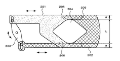
しかしながら、上述したような特許文献1に記載されたレンズ鏡筒の絞り機構は、図14に示すように、遮光部材からなると共に略U字型の切欠きを有する下プレート201及び上プレート202と、これら下プレート201及び上プレート202をそれぞれスライドさせるスイングアーム203等から構成されていた。そして、モータ(図示しない)でスイングアーム203を所定の角度範囲内で回転させることにより、下プレート201及び上プレート202を相対的にスライドさせて、下プレート201及び上プレート202で構成する絞り部の通光面積(開口量)204を変更可能としていた。   However, the lens barrel diaphragm mechanism described in Patent Document 1 as described above includes a lower plate 201 and an upper plate 202 each having a light shielding member and having a substantially U-shaped notch, as shown in FIG. The lower plate 201 and the upper plate 202 are each composed of a swing arm 203 and the like. Then, by rotating the swing arm 203 within a predetermined angle range with a motor (not shown), the lower plate 201 and the upper plate 202 are relatively slid to form a throttle unit constituted by the lower plate 201 and the upper plate 202. The light transmission area (aperture amount) 204 can be changed.

ところが、絞り部の通光面積(開口量)204を形成するためには、下プレート201及び上プレート202それぞれに一対の腕部205,205及び206,206をそれぞれ設ける必要があった。そのため、絞り機構の幅が絞り部の通光面積(開口量)を最大にしたときの絞り部の幅Lよりも各腕部205,206の幅2α(α+α)だけ広くなってしまい、近年のレンズ鏡筒及びそのレンズ鏡筒を用いた撮像装置全体の小型化、薄型化の要求を満たすことができないという問題があった。   However, in order to form the light transmission area (aperture amount) 204 of the diaphragm, it is necessary to provide a pair of arms 205, 205 and 206, 206 on the lower plate 201 and the upper plate 202, respectively. Therefore, the width of the diaphragm mechanism becomes wider by the width 2α (α + α) of each arm 205, 206 than the width L of the diaphragm when the light transmission area (aperture amount) of the diaphragm is maximized. There has been a problem that the lens barrel and the imaging device using the lens barrel as a whole cannot meet the demands for size reduction and thickness reduction.

このような構成を有するレンズ鏡筒の絞り機構の外形を小さくする対策としては、各腕部205,206の幅αを小さくすることが考えられる。しかしながら、各腕部205,206の幅αを小さくすればする程、下プレート201及び上プレート202の強度が弱くなってしまうため、下プレート201及び上プレート202に折れ、ねじれ、撓み等を発生させるおそれがある。そのため、特に強度が要求されるシャッタ動作において信頼性を確保することが困難になるという問題が生じる。   As a countermeasure for reducing the outer shape of the lens barrel diaphragm mechanism having such a configuration, it is conceivable to reduce the width α of each of the arm portions 205 and 206. However, since the strength of the lower plate 201 and the upper plate 202 becomes weaker as the width α of each arm portion 205, 206 is reduced, the lower plate 201 and the upper plate 202 are bent, twisted, bent, etc. There is a risk of causing. For this reason, there arises a problem that it is difficult to ensure reliability particularly in a shutter operation that requires strength.

また、特許文献2に記載された光学情報読取り装置の結像光学系構造においては、結像レンズの前方に平坦面をなし且つ矩形の透明部材を配置し、この透明部材の一方の平面に透光開口部を除いて遮光被膜を形成することで絞りを構成していが、この絞りは予め所定の大きさに設定されたものであり、所望の大きさに変更することができなかった。そのため、レンズの焦点が合う範囲(被写界深度)を変更して所望の像を得ることができないという問題があった。
特開平11−142906号公報 特開平9−147048号公報
Further, in the imaging optical system structure of the optical information reading device described in Patent Document 2, a flat transparent and rectangular transparent member is arranged in front of the imaging lens, and a transparent surface is formed on one plane of the transparent member. A diaphragm is formed by forming a light-shielding film excluding the light aperture, but this diaphragm is set in advance to a predetermined size and cannot be changed to a desired size. For this reason, there is a problem that a desired image cannot be obtained by changing a range (depth of field) in which the lens is focused.
Japanese Patent Laid-Open No. 11-142906 Japanese Patent Laid-Open No. 9-147048

解決しようとする問題点は、遮光部材からなる2枚のプレートを相対的にスライドさせることで絞り部の通光面積(開口量)を変更可能なレンズ絞り機構を構成すると、絞り機構の幅が絞り部の通光面積(開口量)を最大にしたときの絞り部の幅よりも広くなってしまい、レンズ鏡筒及び撮像装置全体の小型化、薄型化の要求を満たすことができないという点である。   The problem to be solved is that if the lens diaphragm mechanism that can change the light transmission area (aperture amount) of the diaphragm portion by relatively sliding the two plates made of the light shielding member, the width of the diaphragm mechanism is reduced. It is wider than the width of the aperture when the light transmission area (aperture amount) of the aperture is maximized, and the lens barrel and the entire imaging device cannot meet the requirements for downsizing and thinning. is there.

本出願のレンズ絞り機構は、光を透過させる光透過部材からなると共に光の透過を阻止する第1の遮光部を設けた第1の絞り羽根と、光の透過を阻止すると共に第1の遮光部との間で絞り部を形成する第2の遮光部を設けた第2の絞り羽根と、第1の絞り羽根と第2の絞り羽根を相対的にスライドさせて絞り部の開口量を変更可能な羽根駆動手段と、を有することを最も主要な特徴とする。   The lens diaphragm mechanism of the present application includes a first diaphragm blade that includes a light transmissive member that transmits light and includes a first light shielding portion that blocks light transmission, and first light shielding while blocking light transmission. The aperture of the aperture is changed by relatively sliding the second aperture blade and the second aperture blade provided with the second light-shielding portion that forms the aperture portion between the aperture portion and the first aperture blade The most important feature is to have possible blade drive means.

本出願のレンズ絞り機構によれば、光透過部材からなる第1の絞り羽根に第1の遮光部を設けると共に第2の絞り羽根に第2の遮光部を設け、第1の遮光部と第2の遮光部によって絞り部を形成する構成としたため、第1及び第2の絞り羽根の幅を絞り部の最大幅と同等にすることができ、機構全体の幅を狭めて小型化を実現することができる。   According to the lens diaphragm mechanism of the present application, the first diaphragm blade made of the light transmitting member is provided with the first light shielding portion and the second diaphragm blade is provided with the second light shielding portion. Since the diaphragm portion is formed by the two light-shielding portions, the width of the first and second diaphragm blades can be made equal to the maximum width of the diaphragm portion, and the entire mechanism is narrowed to achieve downsizing. be able to.

第1及び第2の絞り羽根の幅を絞り部の最大幅と同等にし、機構全体の幅を狭めて小型化を実現することができる絞り機構を、簡単な構造によって実現した。   An aperture mechanism that can achieve downsizing by making the widths of the first and second aperture blades equal to the maximum width of the aperture and reducing the overall width of the mechanism has been realized with a simple structure.

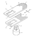
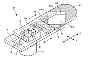
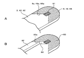
図1〜図13は、本発明のレンズ絞り機構、レンズ鏡筒及び撮像装置の実施の形態の例を説明するものである。即ち、図1はレンズ絞り機構の第1の実施例を示す分解斜視図、図2は図1のレンズ絞り機構の絞り部の開口量を最大にした状態を示す斜視図、図3は同じく開口量を最小に近づけた状態を示す斜視図、図4A,Bは図2及び図3の平面図、図5A,Bは、図1のレンズ絞り機構の遮光部の形状の他の例を示す平面図、図6は図1のレンズ絞り機構を備えたレンズ鏡筒の斜視図、図7は図6のレンズ鏡筒を断面した説明図、図8〜図10は本発明のレンズ絞り機構の第2〜4の実施例を示す斜視図、図11は図1のレンズ絞り機構にNDフィルタを取り付けた状態を説明する説明図、図12は図6のレンズ鏡筒を用いた撮像装置を正面側から見た斜視図、図13は同じく背面側からみた斜視図である。   1 to 13 illustrate examples of embodiments of a lens aperture mechanism, a lens barrel, and an imaging apparatus according to the present invention. That is, FIG. 1 is an exploded perspective view showing a first embodiment of the lens diaphragm mechanism, FIG. 2 is a perspective view showing a state where the aperture of the lens diaphragm mechanism of FIG. 1 is maximized, and FIG. 4A and 4B are plan views of FIGS. 2 and 3, and FIGS. 5A and 5B are plan views showing other examples of the shape of the light shielding portion of the lens diaphragm mechanism of FIG. 6 is a perspective view of a lens barrel provided with the lens aperture mechanism of FIG. 1, FIG. 7 is an explanatory view of the lens barrel of FIG. 6, and FIGS. 8 to 10 are diagrams of a lens aperture mechanism of the present invention. FIGS. 11A and 11B are explanatory views for explaining a state in which an ND filter is attached to the lens diaphragm mechanism of FIG. 1, and FIG. 12 is a front view of an imaging apparatus using the lens barrel of FIG. FIG. 13 is a perspective view seen from the back side.

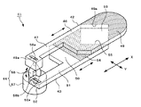
図1〜図4に示すように、本発明の第1の実施例を示すレンズ絞り機構1は、第1の絞り羽根2と、この第1の絞り羽根2に重ね合わせて配置される第2の絞り羽根3と、第1の絞り羽根2と第2の絞り羽根3を相対する方向へスライドさせる羽根駆動手段4等から構成されている。   As shown in FIGS. 1 to 4, the lens diaphragm mechanism 1 according to the first embodiment of the present invention includes a first diaphragm blade 2 and a second diaphragm blade 2 that is disposed so as to overlap the first diaphragm blade 2. And the blade driving means 4 for sliding the first diaphragm blade 2 and the second diaphragm blade 3 in opposite directions.

第1の絞り羽根2は、光を透過させる光透過部材からなっている。この光透過部材としては、例えば、透明アクリル樹脂を挙げることができるが、その他透明ポリカーボネイト等の透明合成樹脂は勿論、透明ガラスを用いることもできる。第1の絞り羽根2は、図1等に示すように、略長方形の板状をなしており、長手方向Xの一側には、光の透過を阻止する第1の遮光部6が設けられており、他側には第1の開口部7が設けられている。   The 1st aperture blade 2 consists of the light transmissive member which permeate | transmits light. As this light transmissive member, for example, a transparent acrylic resin can be used, but other transparent synthetic resins such as transparent polycarbonate can be used, and transparent glass can also be used. As shown in FIG. 1 and the like, the first diaphragm blade 2 has a substantially rectangular plate shape, and on one side in the longitudinal direction X, a first light shielding portion 6 that blocks light transmission is provided. The first opening 7 is provided on the other side.

第1の遮光部6は、第1の絞り羽根2の表面に遮光性塗料を印刷することにより形成されている。本実施例では、遮光性塗料の印刷面を上面としたが、印刷面を下面、又は両面(上面と下面)としてもよい。この第1の遮光部6の長手方向Xに対向する2辺のうちの開口部7側の一辺は、第1の絞り羽根2の幅方向Yの一端から他端まで達する略V字形のV字端部6aとされている。このV字端部6aの頂部は、図1等に示すように、鋭角に形成することに限定されるものではなく、円弧等の曲線で形成するようにしてもよい。更に、V字端部6aは、第1の絞り羽根2の長手方向Xに対向する2辺に直線で接する必要はなく、必要に応じて円弧等の曲線で接するようにしてもよい。第1の絞り羽根2の第1の開口部7は、長手方向Xに延びる略長方形をなしており、幅方向Yに対向する長辺の一方に第1のラック8が設けられている。この第1のラック8には、羽根駆動手段4の後述するギア16が噛合される。   The first light shielding portion 6 is formed by printing a light shielding paint on the surface of the first diaphragm blade 2. In this embodiment, the printing surface of the light-shielding paint is the upper surface, but the printing surface may be the lower surface or both surfaces (upper surface and lower surface). Of the two sides facing the longitudinal direction X of the first light shielding portion 6, one side on the opening 7 side is a substantially V-shaped V-shape extending from one end to the other end in the width direction Y of the first diaphragm blade 2. It is made into the edge part 6a. As shown in FIG. 1 and the like, the top of the V-shaped end 6a is not limited to being formed at an acute angle, but may be formed by a curved line such as an arc. Furthermore, the V-shaped end portion 6a does not need to be in contact with two sides facing the longitudinal direction X of the first aperture blade 2 with a straight line, and may be in contact with a curve such as an arc as necessary. The first opening 7 of the first aperture blade 2 has a substantially rectangular shape extending in the longitudinal direction X, and a first rack 8 is provided on one of the long sides facing the width direction Y. The first rack 8 is engaged with a gear 16 described later of the blade driving means 4.

第2の絞り羽根3は、前述した第1の絞り羽根2と略同様な形状及び構成とされていて、光の透過を阻止する第2の遮光部10と、この第2の遮光部10側の短辺に形成された切欠き部11と、第2の開口部12が設けられている。第2の絞り羽根3の第2の開口部12は、長手方向Xに延びる略長方形をなしており、第1の絞り羽根2に設けた第1の開口部7の第1のラック8と対向する側の長辺に第2のラック13が設けられている。この第2のラック13には、第1のラック8と同様に羽根駆動手段4の後述するギア16が噛合される。   The second diaphragm blade 3 has substantially the same shape and configuration as the first diaphragm blade 2 described above, and includes a second light shielding portion 10 that blocks light transmission, and the second light shielding portion 10 side. A notch 11 formed on the short side and a second opening 12 are provided. The second opening 12 of the second diaphragm blade 3 has a substantially rectangular shape extending in the longitudinal direction X and faces the first rack 8 of the first opening 7 provided in the first diaphragm blade 2. A second rack 13 is provided on the long side on the side to be operated. Like the first rack 8, the second rack 13 is engaged with a gear 16 (described later) of the blade driving means 4.

第2の絞り羽根3の第2の遮光部10は、第1の絞り羽根2の第1の遮光部6と同様に第2の絞り羽根3の表面(上面)に遮光用塗料を印刷して形成されている。第2の絞り羽根3の切欠き部11は、幅方向Yの一端から他端まで達する略V字形に形成されていて、幅方向Yに関して第1の遮光部6のV字端部6aと対称とされている。この切欠き部11も、前述した第1の絞り羽根2のV字端部6aと同様に、その頂部を円弧等の曲線で形成するようにしたり、第2の絞り羽根3の長手方向Xに対向する2辺側の形状を円弧等の曲線としてもよい。かくして、図2等に示すように、第1の絞り羽根2に設けた第1の遮光部6のV字端部6aと、第2の絞り羽根3の第2の遮光部10側の切欠き部11とによって略矩形をなす光の透過(通過)が可能な開口窓、即ち、絞り部18が形成される。   The second light shielding unit 10 of the second diaphragm blade 3 prints a light shielding paint on the surface (upper surface) of the second diaphragm blade 3 in the same manner as the first light shielding unit 6 of the first diaphragm blade 2. Is formed. The cutout portion 11 of the second diaphragm blade 3 is formed in a substantially V shape extending from one end to the other end in the width direction Y, and is symmetrical with respect to the V shape end portion 6a of the first light shielding portion 6 with respect to the width direction Y. It is said that. Similarly to the V-shaped end portion 6a of the first diaphragm blade 2 described above, the notch portion 11 may also have a top portion formed by a curved line such as an arc, or in the longitudinal direction X of the second diaphragm blade 3. The shape on the two opposite sides may be a curved line such as an arc. Thus, as shown in FIG. 2 and the like, the V-shaped end 6a of the first light-shielding portion 6 provided on the first diaphragm blade 2 and the notch on the second light-shielding portion 10 side of the second diaphragm blade 3 are provided. An aperture window capable of transmitting (passing) light having a substantially rectangular shape with the portion 11, that is, a diaphragm portion 18 is formed.

羽根駆動手段4は、モータの一具体例を示すスッテッピンモータ15と、このスッテッピングモータ15の回転軸に固定されたギア16と、各絞り羽根2,3に設けた開口部7,12のそれぞれのラック8,13からなっている。   The blade driving means 4 includes a stepping motor 15 showing a specific example of the motor, a gear 16 fixed to the rotation shaft of the stepping motor 15, and openings 7 provided on the diaphragm blades 2, 3. It consists of 12 racks 8 and 13 respectively.

羽根駆動手段4のギア16の直径は、第1及び第2の開口部7,12の短辺の長さと略同一に設定されており、各ラック8,13にそれぞれ噛合されている。これにより、ギア16の回転動作が、第1及び第2の絞り羽根2,3の長手方向Xのスライド動作に変換される。しかも、第1のラック8と第2のラック13は、ギア16を挟むように互いに対向されているため、第1の絞り羽根2と第2の絞り羽根3は、相対する方向にスライド動作するようになっている。その結果、第1の絞り羽根2に設けた第1の遮光部6のV字端部6aと第2の絞り羽根3の切欠き部11によって形成される絞り部18の開口量を任意に変更することができる。   The diameter of the gear 16 of the blade driving means 4 is set to be substantially the same as the length of the short sides of the first and second openings 7 and 12 and meshes with the racks 8 and 13, respectively. Thereby, the rotation operation of the gear 16 is converted into the slide operation in the longitudinal direction X of the first and second aperture blades 2 and 3. In addition, since the first rack 8 and the second rack 13 are opposed to each other so as to sandwich the gear 16, the first diaphragm blade 2 and the second diaphragm blade 3 slide in the opposite directions. It is like that. As a result, the opening amount of the aperture portion 18 formed by the V-shaped end portion 6a of the first light shielding portion 6 provided on the first aperture blade 2 and the notch portion 11 of the second aperture blade 3 is arbitrarily changed. can do.

本実施例では、第1の絞り羽根2の第1の遮光部6にV字端部6aを設け、第2の絞り羽根3に略V字形の切欠き部11を設けることで、略矩形の絞り部18を形成したが、図5A,Bに示すように、第1の絞り羽根2の第1の遮光部6に半円端部6bを設け、第2の絞り羽根3に半円形の切欠き部17を設けて絞り部19を形成することもできる。この場合、絞り部19は両外側に突となる略楕円形(図5B参照)に形成され、開口量が最大になったときに略円形(図5A参照)に形成される。   In this embodiment, a V-shaped end portion 6a is provided in the first light-shielding portion 6 of the first diaphragm blade 2, and a substantially V-shaped cutout portion 11 is provided in the second diaphragm blade 3, whereby a substantially rectangular shape is obtained. Although the aperture portion 18 is formed, as shown in FIGS. 5A and 5B, the first light shielding portion 6 of the first aperture blade 2 is provided with a semicircular end 6b, and the second aperture blade 3 is cut into a semicircular shape. It is also possible to form the narrowed portion 19 by providing the notch portion 17. In this case, the throttle part 19 is formed in a substantially elliptical shape (see FIG. 5B) that protrudes on both outer sides, and is formed in a substantially circular shape (see FIG. 5A) when the opening amount becomes maximum.

また、本実施例では、遮光性塗料を印刷することで第1及び第2の遮光部5,10を形成したが、本発明に係るレンズ絞り機構に設ける遮光部としては、遮光性塗料の印刷に限定されるものではなく、遮光性塗料の蒸着、塗装は勿論、各絞り羽根の表面に化学処理を行うことや、別部材(例えば遮光性フィルム)を貼り付けることで形成することも可能である。   Further, in this embodiment, the first and second light shielding portions 5 and 10 are formed by printing a light shielding paint. However, as the light shielding portion provided in the lens aperture mechanism according to the present invention, printing of the light shielding paint is performed. It is not limited to the above, and it is possible to form the light by applying chemical treatment to the surface of each diaphragm blade or attaching another member (for example, light-shielding film) as well as vapor-deposition and coating of the light-shielding paint. is there.

更に、本実施例では、第2の絞り羽根3を光透過部材によって形成したが、本発明に係るレンズ絞り機構の第2の絞り羽根としては、光透過部材に限定されるものではなく、例えば、光の透過を阻止する遮光部材、所定の量の光を透過させる光透過率の低い部材等で形成することもできる。なお、第2の絞り羽根3を遮光部材で形成する場合は、第2の絞り羽根2に第2の遮光部10を設ける必要がなく、作業工程を削減して作業効率の向上を図ることができる。   Further, in the present embodiment, the second diaphragm blade 3 is formed by the light transmitting member, but the second diaphragm blade of the lens diaphragm mechanism according to the present invention is not limited to the light transmitting member, for example, It can also be formed of a light blocking member that blocks light transmission, a member with low light transmittance that transmits a predetermined amount of light, or the like. When the second diaphragm blade 3 is formed of a light shielding member, it is not necessary to provide the second light shielding portion 10 on the second diaphragm blade 2, and the work process can be reduced to improve the work efficiency. it can.

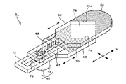
このような構成を有するレンズ絞り機構1によれば、次のようにして絞り部18の開口量の変更が実行される。まず、絞り部18の開口量を大きくするには、羽根駆動手段4のステッピングモータ15によってギア16を、図2に示す状態を上方から見て時計と同じ方向に回転させる。これにより、第1の絞り羽根2が第1の遮光部6をギア16から遠ざける方向にスライド移動すると共に、第2の絞り羽根3が第2の遮光部10をギア16に近づける方向にスライド移動する。その結果、絞り部18の開口量が徐々に増加し、図4A等に示すように、絞り部18の幅が第1及び第2の絞り羽根部2,3の幅と同等となるとき、絞り部18の開口量が最大となる。   According to the lens aperture mechanism 1 having such a configuration, the aperture amount of the aperture section 18 is changed as follows. First, in order to increase the opening amount of the aperture section 18, the gear 16 is rotated in the same direction as the watch as viewed from above by the stepping motor 15 of the blade driving means 4. As a result, the first diaphragm blade 2 slides in a direction to move the first light shielding portion 6 away from the gear 16, and the second diaphragm blade 3 slides in a direction to bring the second light shielding portion 10 closer to the gear 16. To do. As a result, when the opening amount of the diaphragm 18 gradually increases and the width of the diaphragm 18 becomes equal to the width of the first and second diaphragm blades 2 and 3 as shown in FIG. The opening amount of the portion 18 is maximized.

また、絞り部18の開口量を小さくするには、羽根駆動手段4のステッピングモータ15によってギア16を、図2に示す状態を上方から見て時計と反対方向に回転させる。これにより、第1及び第2の絞り羽根2,3は、絞り部18の開口量を大きくする場合と逆の方向にそれぞれスライド移動する。即ち、第1の絞り羽根2が第1の遮光部6をギア16に近づける方向にスライド移動すると共に、第2の絞り羽根3が第2の遮光部10をギア16から遠ざける方向にスライド移動する。その結果、絞り部18の開口量が徐々に減少し、図4B等に示すように、絞り部18の開口量を可及的に小さくし、更には完全に閉じることができる。   Further, in order to reduce the opening amount of the aperture portion 18, the gear 16 is rotated in the opposite direction to the clock as viewed from above by the stepping motor 15 of the blade driving means 4. As a result, the first and second aperture blades 2 and 3 slide in the opposite directions to the case where the aperture amount of the aperture section 18 is increased. That is, the first diaphragm blade 2 slides in a direction to bring the first light shielding portion 6 closer to the gear 16, and the second diaphragm blade 3 slides in a direction to move the second light shielding portion 10 away from the gear 16. . As a result, the opening amount of the diaphragm portion 18 gradually decreases, and as shown in FIG. 4B and the like, the opening amount of the diaphragm portion 18 can be made as small as possible and can be completely closed.

このような構成を有するレンズ絞り機構1によれば、第1及び第2の絞り羽根2,3の幅を絞り部18の最大幅と同等にすることができ、機構全体の幅を狭めて小型化を実現することができる。また、第1及び第2の絞り羽根2,3は平板状をなしているため、強度を確保しながら各絞り羽根2,3の厚みを薄くすることができる。その結果、各絞り羽根2,3が軽くなり、シャッタスピードの性能を向上することができる。   According to the lens diaphragm mechanism 1 having such a configuration, the widths of the first and second diaphragm blades 2 and 3 can be made equal to the maximum width of the diaphragm unit 18, and the overall width of the mechanism can be narrowed to reduce the size. Can be realized. Further, since the first and second diaphragm blades 2 and 3 have a flat plate shape, the thickness of each diaphragm blade 2 and 3 can be reduced while ensuring strength. As a result, the diaphragm blades 2 and 3 are lightened, and the shutter speed performance can be improved.

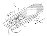
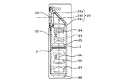
図6及び図7は、前述したような構成を有するレンズ絞り機構1を備えたレンズ鏡筒の一具体例を示すレンズ鏡筒21の図である。このレンズ鏡筒21は、鏡筒本体22と、この鏡筒本体22に固定又は移動可能に保持された5組のレンズ群23,24,25,26,27と、レンズ絞り機構1と、撮像手段の一具体例を示すCCD(撮像素子)28等を備えて構成されている。   FIGS. 6 and 7 are views of a lens barrel 21 showing a specific example of a lens barrel provided with the lens diaphragm mechanism 1 having the above-described configuration. The lens barrel 21 includes a lens barrel body 22, five groups of lens groups 23, 24, 25, 26, and 27, which are fixedly or movably held by the lens barrel body 22, the lens aperture mechanism 1, and imaging. A CCD (imaging device) 28 showing a specific example of the means is provided.

鏡筒本体22は、内部に光の通る光通路30が設けられた筒状の鏡筒部31と、この鏡筒部31の光通路30に連続してレンズ絞り機構1の一部を収納する絞り機構収納部32からなっている。   The lens barrel main body 22 houses a cylindrical lens barrel portion 31 provided with an optical passage 30 through which light passes, and a part of the lens aperture mechanism 1 continuously to the optical passage 30 of the lens barrel portion 31. The aperture mechanism storage unit 32 is provided.

鏡筒本体22の絞り機構収納部32には、レンズ絞り機構1の各絞り羽根2,3の第1及び第2の開口部7,12側とギア16が収納されており、その他の部分、即ち、絞り部18を形成する部分が光通路30内に配置されている。この際、レンズ絞り機構1の第1及び第2の絞り羽根2,3の幅方向Yの両側面と鏡筒本体22の内面との間には、図示しない予圧手段が介在されている。この予圧手段としては、板ばねを挙げることができるが、例えば、ゴム状弾性体やコイルばねを用いることもできる。これにより、各絞り羽根2,3の幅方向Yへの振れを防止して絞り部18の精度を向上させることができる。また、絞り機構収納部32の下面には、図に表れない貫通孔が設けられていて、この貫通孔をステッピングモータ15の回転軸が貫通してギア16と固定されている。   The aperture mechanism storage section 32 of the lens barrel body 22 stores the first and second openings 7 and 12 side of the aperture blades 2 and 3 of the lens aperture mechanism 1 and the gear 16, and the other parts. That is, a portion that forms the aperture 18 is disposed in the light path 30. At this time, preload means (not shown) is interposed between both side surfaces in the width direction Y of the first and second aperture blades 2 and 3 of the lens aperture mechanism 1 and the inner surface of the barrel main body 22. As this preloading means, a leaf spring can be cited, but for example, a rubber-like elastic body or a coil spring can be used. As a result, the diaphragm blades 2 and 3 can be prevented from swinging in the width direction Y, and the precision of the diaphragm portion 18 can be improved. Further, a through hole not shown in the drawing is provided on the lower surface of the diaphragm mechanism housing portion 32, and the rotation shaft of the stepping motor 15 passes through the through hole and is fixed to the gear 16.

鏡筒部31の光通路30の上部には正面に開口する被写体側の開口部33が設けられている。そして、光通路30の開口部33と反対側の下部にはCCD28が配置されている。鏡筒部31の光通路30の開口部31には、第1固定レンズ群23が配置され、光通路30の中途部には第2固定レンズ群25が配置され、光通路30の他端部には第3固定レンズ群27が配置されている。そして、第1固定レンズ群23と第2固定レンズ群25との間に第1可動レンズ群24が配置され、第2固定レンズ群25と第3固定レンズ群27との間に第2可動レンズ群26が配置されている。   An object-side opening 33 that opens to the front is provided in the upper portion of the optical path 30 of the lens barrel 31. A CCD 28 is disposed at the lower portion of the light path 30 opposite to the opening 33. The first fixed lens group 23 is disposed in the opening 31 of the optical path 30 of the lens barrel 31, the second fixed lens group 25 is disposed in the middle of the optical path 30, and the other end of the optical path 30. The third fixed lens group 27 is disposed in the lens. The first movable lens group 24 is disposed between the first fixed lens group 23 and the second fixed lens group 25, and the second movable lens is disposed between the second fixed lens group 25 and the third fixed lens group 27. A group 26 is arranged.

更に、第2固定レンズ群25と第2可動レンズ群26との間にレンズ絞り機構1の絞り部18を形成する部分が配置されている。5組のレンズ群23〜27は、互いの光軸が1つの光軸上に一致するように同軸上に設定されていて、その光軸CLに絞り部18の中心が一致するようにレンズ絞り機構1が配置されている。   Further, a portion for forming the diaphragm portion 18 of the lens diaphragm mechanism 1 is disposed between the second fixed lens group 25 and the second movable lens group 26. The five lens groups 23 to 27 are set coaxially so that their optical axes coincide with each other on one optical axis, and the lens apertures so that the center of the diaphragm portion 18 coincides with the optical axis CL. A mechanism 1 is arranged.

第1固定レンズ群23は、被写体に対向される撮影レンズ23aと、この撮影レンズ23aに対向される三角プリズム23bと、この三角プリズム23bの他面に対向されるレンズ23cとの組み合わせによって構成されている。これにより、被写体からの光が撮影レンズ23aから入射され、三角プリズム23bで90度方向変換されて、レンズ23cから下方に導かれるようになっている。   The first fixed lens group 23 includes a combination of a photographing lens 23a facing the subject, a triangular prism 23b facing the photographing lens 23a, and a lens 23c facing the other surface of the triangular prism 23b. ing. As a result, light from the subject is incident from the photographing lens 23a, converted in direction by 90 degrees by the triangular prism 23b, and guided downward from the lens 23c.

第1可動レンズ群24は、図示しないレンズ移動機構により光軸CLに沿って進退移動可能に構成されており、これにより、ズームレンズが構成されている。即ち、第1可動レンズ群24が第1固定レンズ群23に近づく方向へ移動すると望遠となり、その逆に第2固定レンズ群25に近づく方向へ移動すると広角となる。また、第2可動レンズ群26は、図示しないレンズ移動機構により光軸CLに沿って進退移動可能とされており、これにより、フォーカスレンズが構成されている。   The first movable lens group 24 is configured to be movable back and forth along the optical axis CL by a lens moving mechanism (not shown), thereby forming a zoom lens. That is, when the first movable lens group 24 moves in the direction approaching the first fixed lens group 23, the telephoto lens becomes telephoto, and conversely, when the first movable lens group 24 moves in the direction approaching the second fixed lens group 25, the wide angle angle is obtained. Further, the second movable lens group 26 can be moved back and forth along the optical axis CL by a lens moving mechanism (not shown), thereby forming a focus lens.

レンズ絞り機構1は、前述したように、羽根駆動手段4により第1及び第2の絞り羽根2,3を相対的にスライドさせて、光軸CLを中心に絞り部18の開口量を変更可能に構成されており、これにより、第2可動レンズ26に入射される光の量が調節可能とされている。かくして、被写体からの光は、各レンズ群23〜27及び絞り機構1の絞り部18を通ってCCD28に入射され、電気的な信号に変換される。   As described above, the lens diaphragm mechanism 1 can change the opening amount of the diaphragm portion 18 around the optical axis CL by relatively sliding the first and second diaphragm blades 2 and 3 by the blade driving means 4. Thus, the amount of light incident on the second movable lens 26 can be adjusted. Thus, the light from the subject enters the CCD 28 through the lens groups 23 to 27 and the diaphragm 18 of the diaphragm mechanism 1 and is converted into an electrical signal.

このような構成を有するレンズ鏡筒21に本願発明のレンズ絞り機構1を適用することにより、レンズ鏡筒21の幅を狭くして小型化、薄型化を実現することができる。   By applying the lens diaphragm mechanism 1 of the present invention to the lens barrel 21 having such a configuration, the lens barrel 21 can be made narrower and smaller and thinner.

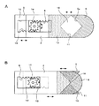
図8には、上述したようなレンズ鏡筒21に適用される本発明のレンズ絞り機構の第2の実施例を示している。この第2の実施例に係るレンズ絞り機構41は、第1の絞り羽根42と、この第1の絞り羽根42に重ね合わせて配置される第2の絞り羽根43と、第1の絞り羽根42と第2の絞り羽根43を相対的にスライドさせる羽根駆動手段44等から構成されている。   FIG. 8 shows a second embodiment of the lens diaphragm mechanism of the present invention applied to the lens barrel 21 as described above. The lens diaphragm mechanism 41 according to the second embodiment includes a first diaphragm blade 42, a second diaphragm blade 43 arranged so as to overlap the first diaphragm blade 42, and the first diaphragm blade 42. And blade driving means 44 for sliding the second diaphragm blade 43 relatively.

第1の絞り羽根42は、光を透過させる光透過部材からなり、略長方形の板状をなす羽根本体46と、この羽根本体46の1つの角部に連続して形成されている腕部47と、この腕部47の先端に設けられたカム部48からなっている。   The first diaphragm blade 42 is made of a light transmitting member that transmits light, and has a substantially rectangular plate-like blade body 46 and an arm portion 47 formed continuously at one corner of the blade body 46. And a cam portion 48 provided at the tip of the arm portion 47.

第1の絞り羽根42の羽根本体46の上面には、長手方向Xの腕部47と反対側に光の透過を阻止する第1の遮光部49が設けられている。この第1の遮光部49は、第1の実施例における第1の絞り羽根2に設けた第1の遮光部6と同一の形状とされていて、V字端部49aを有している。また、第1の絞り羽根42のカム部48の略中央部には、上下面を貫通する第1の被操作部としての長穴48aが設けられており、この長穴48aには羽根駆動手段44の後述する回動アーム58の係合ピン58aが摺動可能に係合される。   On the upper surface of the blade main body 46 of the first diaphragm blade 42, a first light blocking portion 49 that blocks light transmission is provided on the side opposite to the arm portion 47 in the longitudinal direction X. The first light shielding portion 49 has the same shape as the first light shielding portion 6 provided on the first diaphragm blade 2 in the first embodiment, and has a V-shaped end portion 49a. Further, an elongated hole 48a as a first operated portion penetrating the upper and lower surfaces is provided at a substantially central portion of the cam portion 48 of the first diaphragm blade 42, and blade driving means is provided in the elongated hole 48a. An engagement pin 58a of a later-described rotation arm 58 of 44 is slidably engaged.

第2の絞り羽根43は、第1の絞り羽根42と略同様な構成とされていて、略長方形の板状をなす羽根本体50と、この羽根本体50の1つの角部に連続して形成されている腕部51と、この腕部51の先端に設けられたカム部52からなっている。   The second diaphragm blade 43 is configured in substantially the same manner as the first diaphragm blade 42, and is formed continuously with a blade body 50 having a substantially rectangular plate shape and one corner of the blade body 50. The arm portion 51 and the cam portion 52 provided at the tip of the arm portion 51 are provided.

第2の絞り羽根43の羽根本体50には、光の透過を阻止する第2の遮光部54と、切欠き部55が設けられており、これら第2の遮光部54及び切欠き部55は、第1の実施例における第2の絞り羽根3の第2の遮光部10及び切欠き部13と同一の形状とされている。これにより、第1の絞り羽根42に設けた第1の遮光部49のV字端部49aと、第2の絞り羽根43の切欠き部55とによって第1の実施例の絞り部18と同様の絞り部59が形成される。また、第2の絞り羽根43のカム部52の略中央部には、上下面を貫通する第2の被操作部としての長穴52aが設けられており、この長穴52aには羽根駆動手段44の後述する回動アーム58の係合ピン58bが摺動可能に係合される。   The blade body 50 of the second diaphragm blade 43 is provided with a second light-blocking portion 54 that blocks light transmission and a notch 55, and the second light-blocking portion 54 and the notch 55 are In the first embodiment, the second diaphragm blade 3 has the same shape as the second light shielding portion 10 and the notch portion 13 of the second diaphragm blade 3. Accordingly, the V-shaped end portion 49a of the first light shielding portion 49 provided on the first diaphragm blade 42 and the cutout portion 55 of the second diaphragm blade 43 are the same as those of the diaphragm portion 18 of the first embodiment. The narrowed portion 59 is formed. Further, an elongated hole 52a as a second operated portion penetrating the upper and lower surfaces is provided at a substantially central portion of the cam portion 52 of the second diaphragm blade 43, and blade driving means is provided in the elongated hole 52a. An engagement pin 58b of a rotation arm 58 described later of 44 is slidably engaged.

羽根駆動手段44は、モータの一具体例を示すスッテッピンモータ57と、このスッテッピングモータ57の回転軸に固定された回動アーム58と、各絞り羽根42,43のカム部48,52にそれぞれ設けた長穴48a,52aからなっている。回動アーム58は、略菱形をなした所定の厚みを有する板体からなっており、その中心部がスッテッピングモータ57の回転軸に固定されている。この回動アーム58の上面には、中心部から等間隔をおいて長手方向の両端に配置される第1及び第2の操作部としての一対の係合ピン58a,58bが設けられている。   The blade driving means 44 includes a stepping motor 57 showing a specific example of the motor, a rotating arm 58 fixed to the rotation shaft of the stepping motor 57, cam portions 48 of the diaphragm blades 42 and 43, It consists of long holes 48a and 52a provided in 52 respectively. The rotating arm 58 is formed of a plate having a predetermined rhombus shape and having a predetermined thickness, and the central portion thereof is fixed to the rotating shaft of the stepping motor 57. A pair of engagement pins 58a and 58b are provided on the upper surface of the rotating arm 58 as first and second operation portions disposed at both ends in the longitudinal direction at equal intervals from the center portion.

回動アーム58の一対の係合ピン58a,58bは、上述したように、各絞り羽根42,43のカム部48,52に設けた長穴48a,52aにそれぞれ摺動可能に係合されている。これにより、回動アーム58の回動は、各カム部48,52の長穴48a,52aで許容されて、各絞り羽根42,43の相対的なスライド動作に変換される。   As described above, the pair of engaging pins 58a and 58b of the rotating arm 58 are slidably engaged with the long holes 48a and 52a provided in the cam portions 48 and 52 of the diaphragm blades 42 and 43, respectively. Yes. Thereby, the rotation of the rotation arm 58 is permitted by the long holes 48 a and 52 a of the cam portions 48 and 52, and is converted into a relative sliding operation of the diaphragm blades 42 and 43.

本実施例では、回動アーム58に第1及び第2の操作部として一対の係合ピン58a,58bを設け、これら係合ピン58a,58bが摺動可能に係合される第1及び第2の被操作部としての長穴48a,52aを各絞り羽根42,43にそれぞれ設ける構成としたが、回動アームに第1及び第2の操作部として一対の長穴を設け、各絞り羽根42,43に第1及び第2の被操作部としてそれぞれ係合ピンを設けることもできるものである。   In the present embodiment, a pair of engaging pins 58a and 58b are provided as first and second operating portions on the rotating arm 58, and the first and second engaging pins 58a and 58b are slidably engaged. Although the long holes 48a and 52a as the two operated parts are provided in the respective diaphragm blades 42 and 43, a pair of long holes are provided as the first and second operating parts in the rotating arm, and each of the diaphragm blades is provided. 42 and 43 can be provided with engaging pins as first and second operated parts, respectively.

このような構成を有するレンズ絞り機構41によれば、次のようにして絞り部59の開口量の変更が実行される。まず、絞り部59の開口量を大きくするには、羽根駆動手段44のステッピングモータ57によって回動アーム58を、図8に示す状態を上方から見て時計と同じ方向に回動させる。これにより、回動アーム58の係合ピン58aが、第1の絞り羽根42の長穴48a内を摺動しながらステッピングモータ57の回転軸を中心に回動して、第1の絞り羽根42をステッピングモータ15から離れる方向にスライド移動させる。これと同時に、回動アーム58の係合ピン58bが、第2の絞り羽根43の長穴52a内を摺動しながらステッピングモータ57の回転軸を中心に回動して、第2の絞り羽根43をステッピングモータ15に近づく方向、即ち、第1の絞り羽根42のスライド方向と逆方向にスライド移動させる。その結果、絞り部59の開口量が徐々に増加し、図8に示す状態、即ち、絞り部59の幅が第1及び第2の絞り羽根42,43の幅と同等となるとき、絞り部59の開口量が最大となる。   According to the lens aperture mechanism 41 having such a configuration, the aperture amount of the aperture section 59 is changed as follows. First, in order to increase the opening amount of the diaphragm 59, the rotation arm 58 is rotated in the same direction as the clock as viewed from above by the stepping motor 57 of the blade driving means 44. As a result, the engagement pin 58a of the rotation arm 58 rotates about the rotation axis of the stepping motor 57 while sliding in the elongated hole 48a of the first diaphragm blade 42, so that the first diaphragm blade 42 is rotated. Is slid in a direction away from the stepping motor 15. At the same time, the engaging pin 58b of the rotation arm 58 rotates about the rotation axis of the stepping motor 57 while sliding in the elongated hole 52a of the second diaphragm blade 43, and the second diaphragm blade 43 is slid in a direction approaching the stepping motor 15, that is, in a direction opposite to the sliding direction of the first aperture blade 42. As a result, the opening amount of the diaphragm 59 gradually increases, and when the state shown in FIG. 8, that is, when the width of the diaphragm 59 is equal to the width of the first and second diaphragm blades 42 and 43, The opening amount of 59 is the maximum.

また、絞り部59の開口量を小さくするには、羽根駆動手段44のステッピングモータ57によって回動アーム58を、図8に示す状態を上方から見て時計と反対方向に回動させる。これにより、回動アーム58の一対の係合ピン58a,58bが、絞り部59の開口量を大きくする場合とは逆方向に回動して、第1の絞り羽根42をステッピングモータ15に近づく方向に、第2の絞り羽根43をステッピングモータ15から離れる方向にそれぞれスライド移動させる。その結果、絞り部59の開口量が徐々に減少し、第1の実施例と同様に絞り部59の開口量を可及的に小さくし、更には完全に閉じることができる。   Further, in order to reduce the opening amount of the diaphragm 59, the stepping motor 57 of the blade driving means 44 rotates the rotating arm 58 in the opposite direction to the clock as viewed from above in the state shown in FIG. As a result, the pair of engaging pins 58a and 58b of the rotating arm 58 rotate in the direction opposite to the case where the opening amount of the aperture portion 59 is increased, and the first aperture blade 42 approaches the stepping motor 15. The second diaphragm blades 43 are slid in the direction away from the stepping motor 15. As a result, the opening amount of the diaphragm portion 59 is gradually reduced, and the opening amount of the diaphragm portion 59 can be made as small as possible and can be completely closed as in the first embodiment.

このような構成を有するレンズ絞り機構41によれば、第1の実施例と同様な効果を得ることができる。即ち、各絞り羽根42,43の幅を絞り部59の最大幅と同等にすることができ、機構全体の幅を狭めて小型化を実現することができる。更に、第1の実施例よりも各絞り羽根42,43を軽量化することができる。   According to the lens diaphragm mechanism 41 having such a configuration, it is possible to obtain the same effect as that of the first embodiment. That is, the width of each of the diaphragm blades 42 and 43 can be made equal to the maximum width of the diaphragm portion 59, and the entire mechanism can be narrowed to achieve downsizing. Furthermore, the aperture blades 42 and 43 can be made lighter than in the first embodiment.

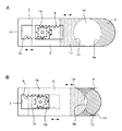
図9には、上述したようなレンズ鏡筒21に適用される本発明のレンズ絞り機構の第3の実施例を示している。この第3の実施例に係るレンズ絞り機構61は、第1の実施例のレンズ絞り機構1と略同様な構成を有しており、第1の絞り羽根62と、第2の絞り羽根63と、第1の絞り羽根62と第2の絞り羽根63を相対的にスライドさせる羽根駆動手段64等から構成されている。   FIG. 9 shows a third embodiment of the lens diaphragm mechanism of the present invention applied to the lens barrel 21 as described above. The lens diaphragm mechanism 61 according to the third embodiment has substantially the same configuration as the lens diaphragm mechanism 1 of the first embodiment, and includes a first diaphragm blade 62, a second diaphragm blade 63, and the like. The first diaphragm blade 62 and the second diaphragm blade 63 are configured by blade driving means 64 that slides relatively.

第1の絞り羽根62は、光を透過させる光透過部材からなり、長手方向Xの一端が幅細に形成された凸状の板体とされている。この第1の絞り羽根62の幅細に形成された部位には第1の開口部67が設けられており、長手方向Xの開口部67と反対側には光の透過を阻止する第1の遮光部66が設けられている。   The first aperture blade 62 is made of a light transmitting member that transmits light, and is a convex plate body in which one end in the longitudinal direction X is narrowly formed. A first opening 67 is provided in a narrowly formed portion of the first diaphragm blade 62, and a first opening that blocks light transmission on the side opposite to the opening 67 in the longitudinal direction X is provided. A light shielding portion 66 is provided.

第1の絞り羽根62の第1の遮光部66は、第1の実施例における第1の絞り羽根2の第1の遮光部6と同一の形状とされていて、V字端部66aを有している。第1の絞り羽根62の第1の開口部67は、長手方向Xに延びる細長の略長方形をなしており、第1の実施例の開口部7に比べ幅が狭く設定されている。この開口部67の幅方向Yに対向する長辺の一方には、第1のラック68が設けられており、この第1のラック68に羽根駆動手段64の後述するギア76が噛合される。   The first light shielding portion 66 of the first diaphragm blade 62 has the same shape as the first light shielding portion 6 of the first diaphragm blade 2 in the first embodiment, and has a V-shaped end portion 66a. is doing. The first aperture 67 of the first aperture blade 62 has an elongated, substantially rectangular shape extending in the longitudinal direction X, and is set to be narrower than the aperture 7 of the first embodiment. A first rack 68 is provided on one of the long sides of the opening 67 facing the width direction Y, and a gear 76 (described later) of the blade driving means 64 is engaged with the first rack 68.

第2の絞り羽根63は、前述した第1の絞り羽根62と略同様な構成及び形状とされていて、光の透過を阻止する第2の遮光部70と、略V字形の切欠き部71と、開口部72を有している。   The second diaphragm blade 63 has substantially the same configuration and shape as the first diaphragm blade 62 described above. The second diaphragm blade 63 blocks the light transmission, and the substantially V-shaped notch 71. And an opening 72.

第2の絞り羽根63の第2の遮光部70及び切欠き部71は、第1の実施例における第2の絞り羽根3の第2の遮光部10及び切欠き部11と同一の形状とされている。これにより、第1の絞り羽根62に設けた第1の遮光部66のV字端部66aと、第2の絞り羽根63の切欠き部71とによって第1の実施例の絞り部18と同様の絞り部78が形成される。   The second light shielding part 70 and the notch part 71 of the second diaphragm blade 63 have the same shape as the second light shielding part 10 and the notch part 11 of the second diaphragm blade 3 in the first embodiment. ing. Accordingly, the V-shaped end portion 66a of the first light shielding portion 66 provided on the first diaphragm blade 62 and the notch portion 71 of the second diaphragm blade 63 are the same as the diaphragm portion 18 of the first embodiment. Is formed.

第2の絞り羽根63の第2の開口部72は、長手方向Xに延びる細長の略長方形をなしており、第1の絞り羽根62に設けた第1の開口部67の第1のラック68と対向する側の長辺に第2のラック73が設けられている。この第2のラック73には、第1のラック68と同様に羽根駆動手段64の後述するギア76が噛合される。   The second opening 72 of the second diaphragm blade 63 has an elongated, substantially rectangular shape extending in the longitudinal direction X, and the first rack 68 of the first opening 67 provided in the first diaphragm blade 62. A second rack 73 is provided on the long side on the opposite side. As with the first rack 68, the second rack 73 is engaged with a gear 76 described later of the blade driving means 64.

羽根駆動手段64は、モータの一具体例を示すスッテッピンモータ75と、このスッテッピングモータ75の回転軸に固定されたギア76と、各絞り羽根62,63に設けた開口部67,72のそれぞれのラック68,73からなっている。   The blade driving means 64 includes a stepping motor 75 showing a specific example of the motor, a gear 76 fixed to the rotation shaft of the stepping motor 75, and openings 67, provided in the diaphragm blades 62 and 63. 72 racks 68 and 73, respectively.

羽根駆動手段64のギア76の直径は、第1及び第2の開口部67,72の短辺の長さと略同一に設定されており、各ラック68,73とそれぞれ噛合されている。これにより、スッテッピングモータ75でギア76を回転させると、第1の実施例と同様に、第1の絞り羽根62と第2の絞り羽根63が相対的にスライド動作するようになっている。その結果、絞り部78の開口量を任意に変更することができる。なお、レンズ絞り機構61の羽根駆動手段64のステッピングモータ75は、第1の実施例におけるステッピングモータ15に比べて高回転が可能なものであり、第1の実施例と同程度の速さで各絞り羽根62,63をスライドさせることができるものである。   The diameter of the gear 76 of the blade driving means 64 is set to be substantially the same as the length of the short sides of the first and second openings 67 and 72 and meshes with the racks 68 and 73, respectively. As a result, when the gear 76 is rotated by the stepping motor 75, the first diaphragm blade 62 and the second diaphragm blade 63 are relatively slid as in the first embodiment. . As a result, the opening amount of the diaphragm portion 78 can be arbitrarily changed. Note that the stepping motor 75 of the blade driving means 64 of the lens aperture mechanism 61 can rotate at a higher speed than the stepping motor 15 in the first embodiment, and is as fast as the first embodiment. The diaphragm blades 62 and 63 can be slid.

このような構成を有するレンズ絞り機構61によれば、第1及び第2の開口部67,72の幅と、これら開口部67,72側の第1及び第2の絞り羽根の幅を幅細にする構成としたため、レンズ絞り機構の更なる小型化、軽量化を図ることができる。しかも、第1及び第2の絞り羽根の開口部67,72側は、レンズ鏡筒21の絞り機構収納部32に収納されるため、この絞り機構収納部32の幅を狭めることができ、レンズ鏡筒21の小型化に寄与することができる。   According to the lens diaphragm mechanism 61 having such a configuration, the widths of the first and second openings 67 and 72 and the widths of the first and second diaphragm blades on the openings 67 and 72 side are narrowed. Therefore, the lens diaphragm mechanism can be further reduced in size and weight. In addition, since the openings 67 and 72 side of the first and second diaphragm blades are housed in the diaphragm mechanism housing section 32 of the lens barrel 21, the width of the diaphragm mechanism housing section 32 can be reduced, and the lens This can contribute to downsizing of the lens barrel 21.

図10には、上述したようなレンズ鏡筒21に適用される本発明のレンズ絞り機構の第4の実施例を示している。この第4の実施例に係るレンズ絞り機構81は、前記第1の実施例における第1の絞り羽根2に、切欠き部86を設けて第1の絞り羽根82を構成したものである。この第4の実施例が前記第1の実施例と異なるところは第1の搾り羽根82のみであるため、その他の構成については同一の符号を付して重複した説明を省略する。   FIG. 10 shows a fourth embodiment of the lens diaphragm mechanism of the present invention applied to the lens barrel 21 as described above. In the lens diaphragm mechanism 81 according to the fourth embodiment, a first diaphragm blade 82 is configured by providing a notch 86 in the first diaphragm blade 2 in the first embodiment. Since the fourth embodiment is different from the first embodiment only in the first squeezing blade 82, the other components are denoted by the same reference numerals, and redundant description is omitted.

レンズ絞り機構81の第1の絞り羽根82は、光を透過させる光透過部材からなり、略長方形の板状をなしている。この第1の絞り羽根82は、第1の実施例における第1の絞り羽根2と略同様の構成を有しており、V字端部83aを有する第1の遮光部83と、ラック85を有する第1の開口部84が設けられている。更に、第1の絞り羽根82の幅方向Yに対向する2つの辺のうちの一辺には、切欠き部86が設けられており、この切欠き部86を設けることで腕部87が形成されている。   The first aperture blade 82 of the lens aperture mechanism 81 is made of a light transmitting member that transmits light, and has a substantially rectangular plate shape. The first diaphragm blade 82 has substantially the same configuration as the first diaphragm blade 2 in the first embodiment, and includes a first light-shielding portion 83 having a V-shaped end portion 83a, and a rack 85. A first opening 84 is provided. Furthermore, a notch 86 is provided on one of the two sides of the first diaphragm blade 82 facing in the width direction Y, and an arm 87 is formed by providing this notch 86. ing.

第1の絞り羽根82の切欠き部86の長手方向Xの長さは、開口量を最大にした絞り部88の長手方向Xの長さよりも長く設定されていると共に、第1の遮光部83側の辺がその第1の遮光部83のV字端部83aに沿って形成されている。第1の絞り羽根82の腕部87は、絞り部88の一部と干渉するように形成されている。しかしながら、この腕部87は、光を透過させる光透過部材からなっているため、絞り部88の一部と干渉していてもその開口量を小さくするおそれはない。これにより、第1及び第2の絞り羽根82,3の幅を絞り部88の最大幅と同等にすることができる。このような構成を有するレンズ絞り機構81によれば、第1の絞り羽根82の軽量化を図ることができ、第1の実施例のレンズ絞り機構1に比べて機構全体を軽くすることができる。   The length in the longitudinal direction X of the notch portion 86 of the first aperture blade 82 is set to be longer than the length in the longitudinal direction X of the aperture portion 88 that maximizes the opening amount, and the first light shielding portion 83. The side edge is formed along the V-shaped end portion 83 a of the first light shielding portion 83. The arm portion 87 of the first diaphragm blade 82 is formed so as to interfere with a part of the diaphragm portion 88. However, since the arm portion 87 is made of a light transmitting member that transmits light, there is no possibility that the opening amount of the arm portion 87 is reduced even if it interferes with a part of the diaphragm portion 88. Thereby, the width of the first and second diaphragm blades 82 and 3 can be made equal to the maximum width of the diaphragm portion 88. According to the lens diaphragm mechanism 81 having such a configuration, the weight of the first diaphragm blade 82 can be reduced, and the entire mechanism can be made lighter than the lens diaphragm mechanism 1 of the first embodiment. .

図11A,Bは、本発明に係るレンズ絞り機構に光調整部の一具体例としてNDフィルタ91を設けた図である。図11Aが第1〜第3の実施例における第1の絞り羽根2,42,62にNDフィルタ91を設けた状態を示し、図11Bが第4の実施例における第1の絞り羽根82にNDフィルタ91を設けた状態を示したものである。   FIGS. 11A and 11B are diagrams in which an ND filter 91 is provided as a specific example of the light adjusting unit in the lens aperture mechanism according to the present invention. FIG. 11A shows a state in which the ND filter 91 is provided on the first diaphragm blades 2, 42, 62 in the first to third embodiments, and FIG. 11B shows ND on the first diaphragm blade 82 in the fourth embodiment. The state where the filter 91 is provided is shown.

図11A,11Bに示す第1〜第4の絞り羽根2,42,62,82に設けたNDフィルタ91の取付位置及びその効果は同様であるため、ここでは、図11Aに示す第1の絞り羽根2を例に挙げて説明する。NDフィルタ91は、入射光の分光組織を変えずに減光するものであり、第1の絞り羽根2に設けた第1の遮光部6のV字端部6aの頂部近傍を覆うように貼り付けられている。これにより、絞り部18の開口量を小さくした状態において、NDフィルタ91がその絞り部18全体を覆うようになっている。その結果、絞り部18によって入射光を減光することができ、被写体が明るく(入射光の光量が多く)且つ絞り部18の開口量が小さい場合に起こりやすい光の回折による画像の劣化を防止することができる。   The mounting positions of the ND filter 91 provided on the first to fourth diaphragm blades 2, 42, 62, and 82 shown in FIGS. 11A and 11B and the effects thereof are the same. Therefore, here, the first diaphragm shown in FIG. 11A is used. The blade 2 will be described as an example. The ND filter 91 is for dimming without changing the spectral structure of the incident light, and is attached so as to cover the vicinity of the top of the V-shaped end portion 6a of the first light shielding portion 6 provided on the first diaphragm blade 2. It is attached. As a result, the ND filter 91 covers the entire diaphragm 18 in a state where the aperture of the diaphragm 18 is small. As a result, incident light can be attenuated by the diaphragm 18, and image degradation due to light diffraction that is likely to occur when the subject is bright (the amount of incident light is large) and the aperture of the diaphragm 18 is small is prevented. can do.

本実施例では、絞り部の開口量を小さくした状態において、NDフィルタ91がその絞り部全体を覆う構成としたが、本発明に係るレンズ絞り機構に設けるNDフィルタとしては、絞り部の開口量が何れの状態においてもその絞り部全体を覆って、入射光を減光する構成とすることができるものである。また、絞り部の開口量の変化に伴って光の透過量が連続的に変化する、例えば、絞り部の開口量が小さくなるに伴って光の透過量を少なくするようなグラデーションを設けることもできるものである。   In this embodiment, the ND filter 91 covers the entire aperture portion in a state where the aperture amount of the aperture portion is small. However, as the ND filter provided in the lens aperture mechanism according to the present invention, the aperture amount of the aperture portion is used. However, in any state, the entire aperture portion can be covered to reduce the incident light. In addition, a gradation may be provided in which the amount of light transmitted continuously changes as the aperture amount of the diaphragm portion changes, for example, the amount of light transmitted decreases as the aperture amount of the aperture portion decreases. It can be done.

更に、本実施例では、NDフィルタ91を第1の遮光部のV字端部の頂点部近傍を覆うように貼り付ける構成としたが、図4Aに示すように、光透過部材が絞り部を覆う構成の場合は、その光透過部材に直接印刷することでNDフィルタを設けることもできる。この場合には、別部材を貼り付ける場合に比べて第1の絞り羽根の厚みの増加を抑制して薄い状態を保持することができると共に、製造工程を簡略化してコストを下げることができる。   Further, in this embodiment, the ND filter 91 is attached so as to cover the vicinity of the apex portion of the V-shaped end of the first light shielding portion. However, as shown in FIG. In the case of the covering configuration, the ND filter can be provided by printing directly on the light transmitting member. In this case, it is possible to keep the thin state by suppressing an increase in the thickness of the first aperture blade as compared with the case of attaching another member, and it is possible to simplify the manufacturing process and reduce the cost.

また、図示しないが、本発明に係るレンズ絞り機構には、光調整部の他の具体例を示す反射防止膜を設けることもできる。この反射防止膜は、光の反射率を減らし、透過率を増すための薄層膜である。このような反射防止膜を、絞り部を覆う光透過部材の表面に施すことにより、被写体側からの入射光の光透過部材の表面での反射を軽減して、画像に生じるゴースト・フレア等を防止することができる。反射防止膜としては、例えば屈折率の異なる薄膜、SiO、TiO、ZnO等を積層させる多層膜を挙げることができるが、MgF等の単層膜でもよく、この種の反射防止膜に使用される各種の膜を用いることができることは勿論である。 Although not shown, the lens diaphragm mechanism according to the present invention may be provided with an antireflection film showing another specific example of the light adjusting unit. This antireflection film is a thin layer film for reducing the reflectance of light and increasing the transmittance. By applying such an antireflection film to the surface of the light transmissive member that covers the aperture portion, reflection of incident light from the subject side on the surface of the light transmissive member is reduced, and ghost, flare, and the like generated in the image are reduced. Can be prevented. Examples of the antireflection film include thin films having different refractive indexes, and multilayer films in which SiO 2 , TiO 2 , ZnO 2 and the like are laminated, but a single layer film such as MgF 2 may be used. Of course, various kinds of films used in the above can be used.

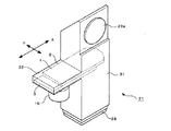
図12及び図13は、前述したような構成を有するレンズ絞り機構1を備えたレンズ鏡筒21を用いた撮像装置の一具体例を示すデジタルスチルカメラ90の図である。このデジタルスチルカメラ90は、情報記録媒体として半導体記録メディアを使用し、光学的な画像をCCD(撮像素子)で電気的な信号に変換して半導体記録メディアに記録したり、液晶ディスプレイ等の表示装置に表示できるようにしたものである。   12 and 13 are diagrams of a digital still camera 90 showing a specific example of an imaging apparatus using the lens barrel 21 having the lens diaphragm mechanism 1 having the above-described configuration. The digital still camera 90 uses a semiconductor recording medium as an information recording medium, converts an optical image into an electrical signal by a CCD (imaging device) and records it on the semiconductor recording medium, or displays on a liquid crystal display or the like. It can be displayed on the device.

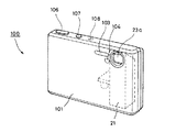
図12及び図13に示すように、デジタルスチルカメラ100は、中空の筐体からなるカメラ本体101と、このカメラ本体101の左上部に配設された撮影レンズ23aを有するレンズ鏡筒21と、このレンズ鏡筒21の下部に配置され、撮影レンズ23aから入力される光に基づいて被写体の映像信号を形成するCCD28(図6等参照)と、このCCD28で形成された映像信号又は予め情報記録媒体に記録されている情報に基づいて映像を表示する液晶ディスプレイ102等から構成されている。   As shown in FIGS. 12 and 13, the digital still camera 100 includes a camera body 101 having a hollow casing, a lens barrel 21 having a photographing lens 23 a disposed on the upper left portion of the camera body 101, and A CCD 28 (see FIG. 6 and the like) that is disposed below the lens barrel 21 and forms a video signal of a subject based on light input from the photographing lens 23a, and a video signal formed by the CCD 28 or information recording in advance. It is composed of a liquid crystal display 102 or the like that displays an image based on information recorded on the medium.

図12に示すように、カメラ本体101の前面には、撮影レンズ23aの近傍にフラッシュ装置103と、セルフタイマランプ104が設けられている。また、カメラ本体101の上面には、電源スイッチである電源ボタン106と、撮影用のシャッタボタン107と、マイクロホン108が設けられている。更に、カメラ本体101の内部空間には、図示しないが、各種の電子部品が実装された配線基板、バッテリー電源、記憶装置、その他各種の電子部品や機械部品、装置等が収納されている。   As shown in FIG. 12, a flash device 103 and a self-timer lamp 104 are provided on the front surface of the camera body 101 in the vicinity of the photographing lens 23a. A power button 106 that is a power switch, a shutter button 107 for photographing, and a microphone 108 are provided on the upper surface of the camera body 101. Further, although not shown, the internal space of the camera body 101 stores a wiring board on which various electronic components are mounted, a battery power source, a storage device, and other various electronic components, mechanical components, devices, and the like.

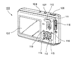
図13に示すように、カメラ本体101の背面には、表示装置の一具体例を示す液晶ディスプレイ102と、ズーム操作を行うことができるズームボタン110と、内蔵スピーカ111と、コントロールボタン112と、メニューボタン113と、画面表示ボタン(LCDバックライトON/OFF)114と、4つの選択ボタン115と、画像サイズ/削除ボタン116等が設けられている。また、カメラ本体101の右側面の上部には、デジタルスチルカメラ100の機能モード、例えば、動画撮影モード、静止画撮影モード、画像再生/編集モード等を切り替えるためのモードスイッチ118が設けられている。   As shown in FIG. 13, on the back of the camera body 101, a liquid crystal display 102 showing a specific example of a display device, a zoom button 110 capable of performing a zoom operation, a built-in speaker 111, a control button 112, A menu button 113, a screen display button (LCD backlight ON / OFF) 114, four selection buttons 115, an image size / delete button 116, and the like are provided. Further, a mode switch 118 for switching a function mode of the digital still camera 100, for example, a moving image shooting mode, a still image shooting mode, an image playback / editing mode, or the like is provided on the upper right side of the camera body 101. .

このような構成を有するデジタルスチルカメラ100に本発明のレンズ絞り機構を備えたレンズ鏡筒を適用することにより、カメラ本体101の幅を狭くすることができ、デジタルスチルカメラ100の小型化、薄型化を実現することができる。   By applying the lens barrel having the lens aperture mechanism of the present invention to the digital still camera 100 having such a configuration, the width of the camera body 101 can be reduced, and the digital still camera 100 can be made smaller and thinner. Can be realized.

以上説明したように、本発明のレンズ絞り機構によれば、第1の絞り羽根を光透過部材によって形成すると共に第1の遮光部を設け、第2の絞り羽根に第1の絞り羽根の第1の遮光部とによって絞り部を形成する第2の遮光部を設けることにより、第1及び第2の絞り羽根の幅を絞り部の最大幅と同等にすることができ、機構全体の幅を狭めて小型化を実現することができる。その結果、本発明のレンズ絞り機構を備えた鏡筒と、この鏡筒を用いた撮像装置全体の小型化、薄型化を実現することができる。   As described above, according to the lens diaphragm mechanism of the present invention, the first diaphragm blade is formed by the light transmitting member, the first light shielding portion is provided, and the second diaphragm blade is provided with the first diaphragm blade. By providing a second light-shielding portion that forms a diaphragm portion with one light-shielding portion, the width of the first and second diaphragm blades can be made equal to the maximum width of the diaphragm portion, and the width of the entire mechanism can be reduced. Narrowing down can be realized. As a result, it is possible to reduce the size and thickness of the lens barrel having the lens aperture mechanism of the present invention and the entire image pickup apparatus using the lens barrel.

本発明は、前述しかつ図面に示した実施の形態に限定されるものではなく、その要旨を逸脱しない範囲内で種々の変形実施が可能である。例えば、前記実施例においては、撮像装置としてデジタルスチルカメラを適用した例について説明したが、その他のスチルカメラは勿論のこと、ビデオカメラ、カメラ付きパーソナルコンピュータ、カメラ付き携帯電話その他の撮像装置に適用できるものである。   The present invention is not limited to the embodiment described above and shown in the drawings, and various modifications can be made without departing from the scope of the invention. For example, in the above-described embodiment, an example in which a digital still camera is applied as an imaging device has been described. However, the present invention is applicable to other imaging cameras, video cameras, personal computers with cameras, mobile phones with cameras, and other imaging devices. It can be done.

本発明のレンズ絞り機構の一実施例を示す分解斜視図である。It is a disassembled perspective view which shows one Example of the lens aperture mechanism of this invention. 本発明のレンズ絞り機構の絞り部の開口量を最大にした状態を示す斜視図である。It is a perspective view which shows the state which maximized the opening amount of the aperture part of the lens aperture mechanism of this invention. 本発明のレンズ絞り機構の絞り部の開口量を最小に近づけた状態を示す斜視図である。It is a perspective view which shows the state which brought the aperture amount of the aperture part of the lens aperture mechanism of this invention close to the minimum. 本発明のレンズ絞り機構の平面図であり、同図Aは図2の絞り部の開口量を最大にした状態を示し、同図Bは図3の絞り部の開口量を最小に近づけた状態を示すものである。2A and 2B are plan views of the lens diaphragm mechanism of the present invention, in which FIG. 2A shows a state in which the aperture amount of the aperture portion in FIG. 2 is maximized, and FIG. Is shown. 図1のレンズ絞り機構に設けた遮光部の他の形状を示す平面図であり、同図Aは絞り部の開口量を最大にした状態を示し、同図Bは絞り部の開口量を最小に近づけた状態を示すものである。FIG. 2 is a plan view showing another shape of a light shielding portion provided in the lens diaphragm mechanism of FIG. 1, in which FIG. A shows a state in which the aperture amount of the aperture portion is maximized, and FIG. It shows a state of being close to. 図1のレンズ絞り機構を備えたレンズ鏡筒を示す説明図である。It is explanatory drawing which shows the lens barrel provided with the lens aperture mechanism of FIG. 図5のレンズ鏡筒を断面して示す説明図である。It is explanatory drawing which shows the lens barrel of FIG. 5 in cross section. 本発明のレンズ絞り機構の第2の実施例を示す斜視図である。It is a perspective view which shows the 2nd Example of the lens aperture mechanism of this invention. 本発明のレンズ絞り機構の第3の実施例を示す斜視図である。It is a perspective view which shows the 3rd Example of the lens aperture mechanism of this invention. 本発明のレンズ絞り機構の第4の実施例を示す斜視図である。It is a perspective view which shows the 4th Example of the lens aperture mechanism of this invention. 本発明のレンズ絞り機構にNDフィルタを取り付けた状態を示す説明図である。It is explanatory drawing which shows the state which attached the ND filter to the lens aperture mechanism of this invention. 図6のレンズ鏡筒を用いた撮像装置を正面側から見た斜視図である。It is the perspective view which looked at the imaging device using the lens-barrel of FIG. 6 from the front side. 図6のレンズ鏡筒を用いた撮像装置を背面側から見た斜視図である。It is the perspective view which looked at the imaging device using the lens-barrel of FIG. 6 from the back side. 従来のレンズ絞り機構の絞り部の開口量を最大にした状態を示す平面図である。It is a top view which shows the state which maximized the opening amount of the aperture part of the conventional lens aperture mechanism.

符号の説明Explanation of symbols

1,41,61,81…レンズ絞り機構、 2,42,62,82…第1の絞り羽根、 3,43,63…第2の絞り羽根、 4,44,64…羽根駆動手段、 6,49,66,83…第1の遮光部、 6a,49a,66a,83a…V字端部、 6b…半円端部、 7,67,84…第1の開口部、 8,68,85…第1のラック、 10,54,70…第2の遮光部、 11,17,55,71…切欠き部、 12,72…第2の開口部、 13,73…第2のラック、 15,57,75…ステッピングモータ(モータ)、 16,76…ギア、 18,19,59,78,88…絞り部、 21…レンズ鏡筒、 22…鏡筒本体(鏡筒)、 31…鏡筒部、 32…絞り機構収納部、 46,50…羽根本体、 47,51…腕部、 48,52…カム部、 48a,52a…長穴(第1及び第2の被操作部)、 58…回動アーム、 58a,58b…係合ピン(第1及び第2の操作部)、 85…切欠き部、 86…腕部、 91…NDフィルタ(光調整部)、 100…デジタルスチルカメラ(撮像装置)、 101…カメラ本体(撮像装置本体)   DESCRIPTION OF SYMBOLS 1,41,61,81 ... Lens diaphragm mechanism, 2,42,62,82 ... 1st aperture blade, 3,43,63 ... 2nd aperture blade, 4,44,64 ... Blade drive means, 6, 49, 66, 83 ... first light shielding part, 6a, 49a, 66a, 83a ... V-shaped end part, 6b ... semicircular end part, 7, 67, 84 ... first opening part, 8, 68, 85 ... 1st rack, 10, 54, 70 ... 2nd light-shielding part, 11, 17, 55, 71 ... notch part, 12, 72 ... 2nd opening part, 13, 73 ... 2nd rack, 15, 57,75 ... stepping motor (motor) 16,76 ... gear, 18, 19,59,78,88 ... throttle part, 21 ... lens barrel, 22 ... lens barrel body (lens barrel), 31 ... lens barrel part 32 ... Aperture mechanism housing part, 46, 50 ... Blade body, 47, 51 ... Arm part, 48, 2 ... cam part, 48a, 52a ... long hole (first and second operated parts), 58 ... rotating arm, 58a, 58b ... engagement pins (first and second operating parts), 85 ... cutting Notch part, 86 ... Arm part, 91 ... ND filter (light adjustment part), 100 ... Digital still camera (imaging device), 101 ... Camera body (imaging device body)

Claims (9)

光を透過させる光透過部材からなると共に前記光の透過を阻止する第1の遮光部を設けた第1の絞り羽根と、
前記光の透過を阻止すると共に前記第1の遮光部との間で絞り部を形成する第2の遮光部を設けた第2の絞り羽根と、
前記第1の絞り羽根と前記第2の絞り羽根を相対的にスライドさせて前記絞り部の開口量を変更可能な羽根駆動手段と、を有することを特徴とするレンズ絞り機構。
A first diaphragm blade comprising a light transmissive member that transmits light and provided with a first light-shielding portion that blocks transmission of the light;
A second diaphragm blade provided with a second light-shielding portion that blocks transmission of the light and forms a diaphragm portion with the first light-shielding portion;
A lens diaphragm mechanism comprising: blade driving means capable of changing an opening amount of the diaphragm portion by relatively sliding the first diaphragm blade and the second diaphragm blade.
前記絞り部は、前記第1の遮光部及び前記第2の遮光部に、前記光の透過が可能な略V字形、半円形、半楕円形又は四角形の光透過部をそれぞれ対向させて設けることにより形成したことを特徴とする請求項1記載のレンズ絞り機構。   The diaphragm portion is provided with a substantially V-shaped, semi-circular, semi-elliptical, or quadrangular light-transmitting portion capable of transmitting the light facing the first light-shielding portion and the second light-shielding portion, respectively. The lens aperture mechanism according to claim 1, wherein the lens aperture mechanism is formed by: 前記絞り部の大きさの最大を、前記第1の絞り羽根及び前記第2の絞り羽根の幅と略一致させたことを特徴とする請求項1記載のレンズ絞り機構。   2. The lens diaphragm mechanism according to claim 1, wherein a maximum size of the diaphragm section is made substantially equal to a width of the first diaphragm blade and the second diaphragm blade. 前記羽根駆動手段は、モータと、当該モータの回転軸に固定されたギアと、前記第1の絞り羽根に設けられて前記ギアに噛合される第1のラックと、前記第2の絞り羽根に設けられると共に前記第1のラックと対向するように配置されて前記ギアに噛合される第2のラックと、からなることを特徴とする請求項1記載のレンズ絞り機構。   The blade driving means includes a motor, a gear fixed to the rotation shaft of the motor, a first rack provided on the first diaphragm blade and meshed with the gear, and the second diaphragm blade. The lens diaphragm mechanism according to claim 1, further comprising: a second rack that is provided so as to be opposed to the first rack and meshed with the gear. 前記羽根駆動手段は、モータと、当該モータの回転軸に固定されると共に当該回転軸を中心として直径方向の一方に設けられた第1の操作部と当該直径方向の他方に設けられた第2の操作部とを有する回動アームと、前記第1の絞り羽根に設けられると共に前記第1の操作部に摺動可能に係合される第1の被操作部と、前記第2の絞り羽根に設けられると共に前記第2の操作部に摺動可能に係合される第2の被操作部と、からなることを特徴とする請求項1記載のレンズ絞り機構。   The blade driving means is fixed to a motor, a rotation shaft of the motor, and has a first operation portion provided at one of the diametrical directions around the rotation shaft and a second operation portion provided at the other of the diametrical directions. A rotating arm having a first operating portion, a first operated portion that is provided on the first aperture blade and is slidably engaged with the first operating portion, and the second aperture blade The lens diaphragm mechanism according to claim 1, further comprising a second operated portion that is slidably engaged with the second operating portion. 前記絞り部の少なくとも一部には、光の透過量を調整可能な光調整部を設けたことを特徴とする請求項2記載のレンズ絞り機構。   3. The lens diaphragm mechanism according to claim 2, wherein a light adjusting unit capable of adjusting a light transmission amount is provided in at least a part of the diaphragm unit. 前記光調整部は、前記第1の絞り羽根又は前記第2の絞り羽根の前記光透過部に直接印刷することにより形成したこと特徴とする請求項6記載レンズ絞り機構。   7. The lens diaphragm mechanism according to claim 6, wherein the light adjusting section is formed by printing directly on the light transmitting section of the first diaphragm blade or the second diaphragm blade. 光を透過させる光透過部材からなると共に前記光の透過を阻止する第1の遮光部を設けた第1の絞り羽根と、前記光の透過を阻止すると共に前記第1の遮光部との間で絞り部を形成する第2の遮光部を設けた第2の絞り羽根と、前記第1の絞り羽根と前記第2の絞り羽根を相対的にスライドさせて前記絞り部の開口量を変更可能な羽根駆動手段と、を設けたレンズ絞り機構と、
前記レンズ絞り機構が取り付けられる鏡筒と、
を有することを特徴とするレンズ鏡筒。
A first diaphragm blade that is formed of a light transmissive member that transmits light and includes a first light shielding portion that blocks light transmission, and between the first light shielding portion that blocks light transmission and the first light shielding portion. The aperture of the aperture can be changed by relatively sliding the first aperture blade and the second aperture blade provided with the second light shielding portion forming the aperture section, and the first aperture blade and the second aperture blade. A lens diaphragm mechanism provided with blade driving means;
A lens barrel to which the lens aperture mechanism is attached;
A lens barrel comprising:
光を透過させる光透過部材からなると共に前記光の透過を阻止する第1の遮光部を設けた第1の絞り羽根と、前記光の透過を阻止すると共に前記第1の遮光部との間で絞り部を形成する第2の遮光部を設けた第2の絞り羽根と、前記第1の絞り羽根と前記第2の絞り羽根を相対的にスライドさせて前記絞り部の開口量を変更可能な羽根駆動手段と、を設けたレンズ絞り機構と、
前記レンズ絞り機構が取り付けられる鏡筒を有するレンズ鏡筒と、
前記レンズ鏡筒が収納される撮像装置本体と、を有することを特徴とする撮像装置。
A first diaphragm blade that is formed of a light transmissive member that transmits light and includes a first light blocking portion that blocks light transmission, and between the first light blocking portion that blocks light transmission and the first light blocking portion. The aperture of the aperture can be changed by relatively sliding the first aperture blade and the second aperture blade provided with the second light shielding portion forming the aperture section, and the first aperture blade and the second aperture blade. A lens diaphragm mechanism provided with blade driving means;
A lens barrel having a lens barrel to which the lens aperture mechanism is attached;
An imaging apparatus comprising: an imaging apparatus main body in which the lens barrel is housed.
JP2005138664A 2005-05-11 2005-05-11 Lens diaphragm mechanism, lens barrel, and imaging device Pending JP2006317618A (en)

Priority Applications (1)

Application Number Priority Date Filing Date Title
JP2005138664A JP2006317618A (en) 2005-05-11 2005-05-11 Lens diaphragm mechanism, lens barrel, and imaging device

Applications Claiming Priority (1)

Application Number Priority Date Filing Date Title
JP2005138664A JP2006317618A (en) 2005-05-11 2005-05-11 Lens diaphragm mechanism, lens barrel, and imaging device

Publications (1)

Publication Number Publication Date
JP2006317618A true JP2006317618A (en) 2006-11-24

Family

ID=37538364

Family Applications (1)

Application Number Title Priority Date Filing Date
JP2005138664A Pending JP2006317618A (en) 2005-05-11 2005-05-11 Lens diaphragm mechanism, lens barrel, and imaging device

Country Status (1)

Country Link
JP (1) JP2006317618A (en)

Cited By (6)

* Cited by examiner, † Cited by third party
Publication number Priority date Publication date Assignee Title
JP2009186673A (en) * 2008-02-05 2009-08-20 Tamron Co Ltd Diaphragm device, lens having diaphragm device, and video camera
KR20140060857A (en) * 2012-11-12 2014-05-21 삼성테크윈 주식회사 Imaging device
CN107850819A (en) * 2015-07-23 2018-03-27 优势电影有限公司 For camera lens or for photo or the ellipticity aperture of film camera
KR20180126705A (en) * 2017-05-18 2018-11-28 삼성전기주식회사 Camera Module
CN113867075A (en) * 2021-10-27 2021-12-31 维沃移动通信有限公司 Aperture modules, camera modules and electronic equipment
WO2023143440A1 (en) * 2022-01-25 2023-08-03 维沃移动通信有限公司 Aperture assembly, camera module, and electronic device

Citations (4)

* Cited by examiner, † Cited by third party
Publication number Priority date Publication date Assignee Title
JPS5888222A (en) * 1981-11-17 1983-05-26 Natl Aerospace Lab Yoke for magnetic bearing
JPH07104343A (en) * 1993-10-07 1995-04-21 Canon Inc Light control device
JP2000010152A (en) * 1998-06-17 2000-01-14 Olympus Optical Co Ltd Diaphragm device
JP2004038114A (en) * 2002-07-08 2004-02-05 Fuji Photo Film Co Ltd Auto-focus camera

Patent Citations (4)

* Cited by examiner, † Cited by third party
Publication number Priority date Publication date Assignee Title
JPS5888222A (en) * 1981-11-17 1983-05-26 Natl Aerospace Lab Yoke for magnetic bearing
JPH07104343A (en) * 1993-10-07 1995-04-21 Canon Inc Light control device
JP2000010152A (en) * 1998-06-17 2000-01-14 Olympus Optical Co Ltd Diaphragm device
JP2004038114A (en) * 2002-07-08 2004-02-05 Fuji Photo Film Co Ltd Auto-focus camera

Cited By (11)

* Cited by examiner, † Cited by third party
Publication number Priority date Publication date Assignee Title
JP2009186673A (en) * 2008-02-05 2009-08-20 Tamron Co Ltd Diaphragm device, lens having diaphragm device, and video camera
KR20140060857A (en) * 2012-11-12 2014-05-21 삼성테크윈 주식회사 Imaging device
KR101726694B1 (en) 2012-11-12 2017-04-13 한화테크윈 주식회사 Imaging device
CN107850819A (en) * 2015-07-23 2018-03-27 优势电影有限公司 For camera lens or for photo or the ellipticity aperture of film camera
EP3339950A1 (en) * 2015-07-23 2018-06-27 Vantage Film GmbH Ellipse-like diaphragm for a camera lens or for a photographic or film camera
JP2018521361A (en) * 2015-07-23 2018-08-02 ヴアンターゲ・フイルム・ゲーエムベーハー Oval aperture device for camera lens or photo or film camera
US10942420B2 (en) 2015-07-23 2021-03-09 Vantage Film Gmbh Ellipse-like aperture for a camera lens assembly or for a photo or film camera
KR20180126705A (en) * 2017-05-18 2018-11-28 삼성전기주식회사 Camera Module
KR102069630B1 (en) * 2017-05-18 2020-01-23 삼성전기주식회사 Camera Module
CN113867075A (en) * 2021-10-27 2021-12-31 维沃移动通信有限公司 Aperture modules, camera modules and electronic equipment
WO2023143440A1 (en) * 2022-01-25 2023-08-03 维沃移动通信有限公司 Aperture assembly, camera module, and electronic device

Similar Documents

Publication Publication Date Title
JP5342465B2 (en) Lens barrel
US8625024B2 (en) Webcam with moveable zoom lens
CN117289438A (en) Periscope type optical module and optical system
CN100451712C (en) lens barrel
CN210839753U (en) Periscopic zooming camera module
CN108600601B (en) Camera Modules, Camera Assemblies and Electronic Devices
CN111866328B (en) A camera module and mobile terminal
CN113286019B (en) Optical module, camera and electronic equipment
CN110266851A (en) Camera module, electronic device, and camera module control method
JP2010266678A (en) Image capturing apparatus
JP2009288494A (en) Light quantity adjusting device, lens barrel, and imaging device
US6340252B1 (en) Light-quantity controlling device and apparatus using the same
CN112822346B (en) Periscopic camera module and electronic equipment
JP2006317618A (en) Lens diaphragm mechanism, lens barrel, and imaging device
CN114185166A (en) Periscopic camera module and terminal equipment
US5598241A (en) Camera having a lens opening
JP4274778B2 (en) camera
JP2006317547A (en) Catoptric system assembling unit and imaging apparatus using same
JP2007192860A (en) Optical path switching device and imaging device
JP5875804B2 (en) Lens barrel and imaging device
JP2023116075A (en) Optical unit, imaging unit, and portable terminal
JP2012048159A (en) Lens barrel and imaging apparatus
CN111885292A (en) Camera shooting mechanism and electronic equipment
JP2017138382A (en) Lens barrel and optical instrument using the same
JP2006301473A (en) Optical system having optical filter and photographing apparatus

Legal Events

Date Code Title Description
A621 Written request for application examination

Free format text: JAPANESE INTERMEDIATE CODE: A621

Effective date: 20080328

A977 Report on retrieval

Free format text: JAPANESE INTERMEDIATE CODE: A971007

Effective date: 20101208

A131 Notification of reasons for refusal

Free format text: JAPANESE INTERMEDIATE CODE: A131

Effective date: 20101214

A02 Decision of refusal

Free format text: JAPANESE INTERMEDIATE CODE: A02

Effective date: 20110426