EP3325362B1 - Emballage renforcé - Google Patents
Emballage renforcé Download PDFInfo
- Publication number
- EP3325362B1 EP3325362B1 EP16828598.9A EP16828598A EP3325362B1 EP 3325362 B1 EP3325362 B1 EP 3325362B1 EP 16828598 A EP16828598 A EP 16828598A EP 3325362 B1 EP3325362 B1 EP 3325362B1
- Authority
- EP
- European Patent Office
- Prior art keywords
- panel
- support
- extending
- fold line
- carton
- Prior art date
- Legal status (The legal status is an assumption and is not a legal conclusion. Google has not performed a legal analysis and makes no representation as to the accuracy of the status listed.)
- Active
Links
- 230000014759 maintenance of location Effects 0.000 claims description 12
- 238000000034 method Methods 0.000 claims description 11
- 239000000463 material Substances 0.000 description 36
- 230000003014 reinforcing effect Effects 0.000 description 8
- 235000013305 food Nutrition 0.000 description 7
- 239000003292 glue Substances 0.000 description 6
- 238000004806 packaging method and process Methods 0.000 description 6
- 239000000123 paper Substances 0.000 description 6
- 230000008901 benefit Effects 0.000 description 4
- 239000004033 plastic Substances 0.000 description 4
- 229920003023 plastic Polymers 0.000 description 4
- 235000013339 cereals Nutrition 0.000 description 3
- 239000004927 clay Substances 0.000 description 3
- 238000004519 manufacturing process Methods 0.000 description 3
- 239000004698 Polyethylene Substances 0.000 description 2
- 239000011248 coating agent Substances 0.000 description 2
- 238000000576 coating method Methods 0.000 description 2
- 238000005520 cutting process Methods 0.000 description 2
- 235000012020 french fries Nutrition 0.000 description 2
- 238000012986 modification Methods 0.000 description 2
- 230000004048 modification Effects 0.000 description 2
- 239000011087 paperboard Substances 0.000 description 2
- -1 polyethylene Polymers 0.000 description 2
- 229920000573 polyethylene Polymers 0.000 description 2
- 235000011890 sandwich Nutrition 0.000 description 2
- XLYOFNOQVPJJNP-UHFFFAOYSA-N water Substances O XLYOFNOQVPJJNP-UHFFFAOYSA-N 0.000 description 2
- 102100036876 Cyclin-K Human genes 0.000 description 1
- 101000713127 Homo sapiens Cyclin-K Proteins 0.000 description 1
- 240000007594 Oryza sativa Species 0.000 description 1
- 235000007164 Oryza sativa Nutrition 0.000 description 1
- 239000000853 adhesive Substances 0.000 description 1
- 230000001070 adhesive effect Effects 0.000 description 1
- 230000004075 alteration Effects 0.000 description 1
- 230000004888 barrier function Effects 0.000 description 1
- 239000011111 cardboard Substances 0.000 description 1
- 238000010276 construction Methods 0.000 description 1
- 230000000994 depressogenic effect Effects 0.000 description 1
- 230000006872 improvement Effects 0.000 description 1
- 239000002655 kraft paper Substances 0.000 description 1
- 239000008267 milk Substances 0.000 description 1
- 210000004080 milk Anatomy 0.000 description 1
- 235000013336 milk Nutrition 0.000 description 1
- 235000009566 rice Nutrition 0.000 description 1
- 239000004576 sand Substances 0.000 description 1
- 238000007789 sealing Methods 0.000 description 1
- 238000003860 storage Methods 0.000 description 1
- 239000002966 varnish Substances 0.000 description 1
- 230000003313 weakening effect Effects 0.000 description 1
Images


Classifications
-
- B—PERFORMING OPERATIONS; TRANSPORTING
- B65—CONVEYING; PACKING; STORING; HANDLING THIN OR FILAMENTARY MATERIAL
- B65D—CONTAINERS FOR STORAGE OR TRANSPORT OF ARTICLES OR MATERIALS, e.g. BAGS, BARRELS, BOTTLES, BOXES, CANS, CARTONS, CRATES, DRUMS, JARS, TANKS, HOPPERS, FORWARDING CONTAINERS; ACCESSORIES, CLOSURES, OR FITTINGS THEREFOR; PACKAGING ELEMENTS; PACKAGES
- B65D5/00—Rigid or semi-rigid containers of polygonal cross-section, e.g. boxes, cartons or trays, formed by folding or erecting one or more blanks made of paper
- B65D5/36—Rigid or semi-rigid containers of polygonal cross-section, e.g. boxes, cartons or trays, formed by folding or erecting one or more blanks made of paper specially constructed to allow collapsing and re-erecting without disengagement of side or bottom connections
- B65D5/3607—Rigid or semi-rigid containers of polygonal cross-section, e.g. boxes, cartons or trays, formed by folding or erecting one or more blanks made of paper specially constructed to allow collapsing and re-erecting without disengagement of side or bottom connections formed by folding or erecting a single blank
- B65D5/3614—Rigid or semi-rigid containers of polygonal cross-section, e.g. boxes, cartons or trays, formed by folding or erecting one or more blanks made of paper specially constructed to allow collapsing and re-erecting without disengagement of side or bottom connections formed by folding or erecting a single blank to form a tubular body, at least one of the ends of the body remaining connected
- B65D5/3628—Rigid or semi-rigid containers of polygonal cross-section, e.g. boxes, cartons or trays, formed by folding or erecting one or more blanks made of paper specially constructed to allow collapsing and re-erecting without disengagement of side or bottom connections formed by folding or erecting a single blank to form a tubular body, at least one of the ends of the body remaining connected collapsed along median lines of two opposite sides of the rectangular tubular body
-
- B—PERFORMING OPERATIONS; TRANSPORTING
- B65—CONVEYING; PACKING; STORING; HANDLING THIN OR FILAMENTARY MATERIAL
- B65D—CONTAINERS FOR STORAGE OR TRANSPORT OF ARTICLES OR MATERIALS, e.g. BAGS, BARRELS, BOTTLES, BOXES, CANS, CARTONS, CRATES, DRUMS, JARS, TANKS, HOPPERS, FORWARDING CONTAINERS; ACCESSORIES, CLOSURES, OR FITTINGS THEREFOR; PACKAGING ELEMENTS; PACKAGES
- B65D5/00—Rigid or semi-rigid containers of polygonal cross-section, e.g. boxes, cartons or trays, formed by folding or erecting one or more blanks made of paper
- B65D5/42—Details of containers or of foldable or erectable container blanks
- B65D5/44—Integral, inserted or attached portions forming internal or external fittings
- B65D5/441—Reinforcements
- B65D5/443—Integral reinforcements, e.g. folds, flaps
-
- B—PERFORMING OPERATIONS; TRANSPORTING
- B65—CONVEYING; PACKING; STORING; HANDLING THIN OR FILAMENTARY MATERIAL
- B65D—CONTAINERS FOR STORAGE OR TRANSPORT OF ARTICLES OR MATERIALS, e.g. BAGS, BARRELS, BOTTLES, BOXES, CANS, CARTONS, CRATES, DRUMS, JARS, TANKS, HOPPERS, FORWARDING CONTAINERS; ACCESSORIES, CLOSURES, OR FITTINGS THEREFOR; PACKAGING ELEMENTS; PACKAGES
- B65D5/00—Rigid or semi-rigid containers of polygonal cross-section, e.g. boxes, cartons or trays, formed by folding or erecting one or more blanks made of paper
- B65D5/42—Details of containers or of foldable or erectable container blanks
- B65D5/56—Linings or internal coatings, e.g. pre-formed trays provided with a blow- or thermoformed layer
- B65D5/60—Loose, or loosely attached, linings
- B65D5/603—Flexible linings loosely glued to the wall of the container
- B65D5/606—Bags or bag-like tubes loosely glued to the wall of a "tubular" container
Definitions
- the present disclosure generally relates to reinforced packages for holding products and to methods of forming the packages. More specifically, the present disclosure is directed to a package including a bag or liner attached to a carton or blank having features to reinforce the shape of the formed package and allow access to the contents of the package.
- Bags or liners such as paper or plastic bags, traditionally have been used for the packaging and transport of products from bulk materials such as rice or sand to larger items. Bags or liners generally are inexpensive and easy to manufacture and can be formed in different configurations and sizes, and can be used for storage and transport of a wide variety of products. In particular, in the food service industry, bags or liners are frequently used for packaging of prepared food items, such as sandwiches, French fries, cereal, etc. Currently, there is a growing demand for bags or liners or similar packages for use in packaging various products, including sandwiches, French fries, cereal, and other prepared food items, for presentation to consumers. However, it is equally important that the costs of such packages necessarily must be minimized as much as possible. While various packages designs including reinforcing or supporting materials have been developed, often, the manufacture of such specialty bags or liners having reinforcing layers or materials supplied thereto has required multiple stages or operations, which can significantly increase the cost of manufacture of such packages.
- JP 2011 189978 A discloses a reinforced package as per the preamble of claim 1. Further reinforced packages and a collapsible receptable are shown in US 2015 / 0083789 A1 and US 904,050 A . These packages / receptables, however, still leave room for improvement.
- the present invention is generally directed to a reinforced package comprising a carton comprising a plurality of panels that extend at least partially around an interior of the carton.
- the plurality of panels comprises a front panel, a first side panel foldably connected to the front panel, a second side panel foldably connected to the front panel, and at least one back panel foldably connected to at least one of the first side panel and the second side panel.
- a bag is attached to the carton and has an at least partially open end, an at least partially closed end, and an interior space for holding a product.
- the carton is positionable in a non-erect position wherein the interior space of the bag is at least partially collapsed and in an erect position wherein the interior space of the bag is increased.
- the carton is configured to support the bag in the erect position and the first side panel, and the second side panel have retention features for at least partially retaining the carton in the erect position.
- the carton further comprises support features extending from at least one panel of the plurality of panels, the first side panel comprises a first panel portion foldably connected to a second panel portion along a first lateral fold line extending in the first side panel, and the support features comprise a first support extending from the first panel portion and a second support extending from the second panel portion.
- the present invention is generally directed to the combination of a carton blank and a bag for forming a reinforced package for holding a product.
- the carton blank is for forming a carton and comprises a plurality of panels comprising a front panel, a first side panel foldably connected to the front panel, a second side panel foldably connected to the front panel, and at least one back panel foldably connected to at least one of the first side panel and the second side panel.
- the bag comprises an at least partially open end, an at least partially closed end, and an interior space for holding a product.
- the bag is at least partially attached to the carton blank.
- the reinforced package formed from the carton blank and the bag are positionable in a non-erect position wherein the interior space of the bag is at least partially collapsed and in an erect position wherein the interior space of the bag is increased.
- the first side panel and the second side panel have retention features for at least partially retaining the carton formed from the carton blank in the erect position.
- the carton blank further comprises support features extending from at least one panel of the plurality of panels, the first side panel comprises a first panel portion foldably connected to a second panel portion along a first lateral fold line extending in the first side panel, and the support features comprise a first support extending from the first panel portion and a second support extending from the second panel portion.
- the present invention is generally directed to a method of forming a reinforced package.
- the method comprises obtaining a carton blank at least partially attached to a bag.
- the carton blank comprises a plurality of panels comprising a front panel, a first side panel foldably connected to the front panel, a second side panel foldably connected to the front panel, and at least one back panel foldably connected to at least one of the first side panel and the second side panel, and the bag comprises an at least partially open end, an at least partially closed end, and an interior space for holding a product.
- the method further comprises forming an interior of a carton at least partially defined by the plurality of panels by folding the plurality of panels at least partially around the bag.
- the carton is positionable in a non-erect position wherein the interior space of the bag is at least partially collapsed and in an erect position wherein the interior space of the bag is increased, the carton being configured to support the bag in the erect position, and the first side panel, the second side panel have retention features for at least partially retaining the carton in the erect position.
- the carton further comprises support features extending from at least one panel of the plurality of panels, the first side panel comprises a first panel portion foldably connected to a second panel portion along a first lateral fold line extending in the first side panel, and the support features comprise a first support extending from the first panel portion and a second support extending from the second panel portion.
- the present disclosure generally relates to a reinforced package for holding products such as food products or other articles.
- Packages according to the present disclosure can accommodate articles of any shape.
- the packages can comprises a bag, liner, or wrap material comprising a relatively flexible material attached to a reinforcing construct comprising a relatively rigid material (e.g., paperboard).
- the bags or liners can generally be made from a paper, plastic or other stock material and can be attached to the reinforcing construct.
- the liners comprise polyethylene material or any other suitable heat-sealable material.
- the reinforcing construct can be of varying widths and can extend about or over the closed ends of the bags, in some embodiments enclosing such closed ends, and will provide support for the bags upon loading with a product or article or series of articles therein.
- the reinforcing construct can be folded with their bags into a configuration supporting the bags in a freestanding, upright and opened condition for ease of loading and ease of use.
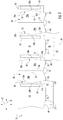
- Fig. 1 illustrates a blank 10 for forming a reinforced package generally indicated at 1 ( Figs. 4-7 ), that includes a bag 3 attached to a carton 5 according to one embodiment of the disclosure.
- the bag has an open top end 7, a closed or sealed bottom end 9, and an interior space 17 for holding a product.
- the bag 3 has sealed sides 19 extending the length of the bag between the top 7 and bottom 9.
- the reinforcing carton 5 can have a bottom 20 that supports the sealed bottom 9 of the bag 3.
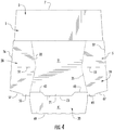
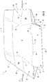
- the carton 5 can be positioned in a non-erected or collapsed configuration ( Figs. 4 and 6 ) and can be positioned an erected or opened configuration ( Figs.
- the bottom 20 of the carton 5 can have support features for allowing the package 1 to be positioned in the upright position of Figs. 5 and 7 .
- the blank 10 has a lateral axis L1 and a longitudinal axis L2.
- the blank 10 has a front panel 21 foldably connected to a first side panel 28 at a first fold line 33.
- the first side panel 28 includes two individual panel portions 28a, 28b foldably connected to one another at lateral fold line 26.
- a first back panel 23 is foldably connected to the first side panel 28 at a second fold line 31.
- a second side panel 29 is foldably connected to the front panel 21 at a third fold line 35.
- the second side panel 29 includes two individual panel portions 29a, 29b foldably connected to one another at lateral fold line 27.
- An attachment flap or second back panel 25 is foldably connected to the second side panel 29 at a fourth fold line 37.
- the blank 10 includes a bottom panel 41 foldably connected to the front panel 21 at a longitudinal fold line 43.
- a first bottom end flap 45 is foldably connected to the first back panel 23 at a longitudinal fold line 47.
- a second bottom end flap 42 can be foldably connected to the bottom panel 41 along a longitudinal fold line 49 extending across the width of the bottom end flap.
- Any of the front panel 21, the back panels 23, 25, the side panels 28, 29, the bottom panel 41, and/or the bottom end flaps 42, 45 could be omitted or could be otherwise arranged, shaped, positioned, and/or configured without departing from the disclosure.
- the first fold line 33 is segmented into two oblique fold line segments 33a, 33b extending from a vertex 38a.
- the second fold line 31 is segmented into two oblique fold line segments 31a, 31b extending from a vertex 38b.
- the third fold line 35 is segmented into two oblique fold line segments 35a, 35b extending from a vertex 39a.
- the fourth fold line 37 is segmented into two oblique fold line segments 37a, 37b extending from a vertex 39b.
- the fold lines 33, 31 can be spaced apart from the lateral fold line 26 so that the vertices 38a, 38b are spaced apart from the lateral fold line 26 farther than the opposite ends of the oblique fold line segments 33a, 33b, 31a, 31b (e.g., the panel portions 28a, 28b and the first side panel 28 are widest between or adjacent the vertices 38a, 38b).
- the fold lines 37, 35 are spaced apart from the lateral fold line 27 so that the vertices 39a, 39b are spaced apart from the lateral fold line 27 farther than the opposite ends of the oblique fold line segments 37a, 37b, 35a, 35b (e.g., the panel portions 29a, 29b and the first side panel 29 are widest between or adjacent the vertices 39a, 39b).
- the fold lines 33, 31, 37, 35 could be omitted or could be otherwise arranged, shaped, positioned, and/or configured without departing from the disclosure.
- the fold lines could be arcuate fold lines rather than segmented fold lines as shown.
- the panel portions 28a, 28b of the first side panel 28 can include a longitudinal fold line 51 extending between the fold lines 31, 33.
- the panel portions 29a, 29b of the second side panel 29 include a longitudinal fold line 53 extending between the fold lines 35, 37.
- the longitudinal fold line 51 can extend from the vertex 38a of the first fold line 33 to the vertex 38b of the second fold line 31 so that the oblique fold line segments 33a, 33b and 31a, 31b extend from respective ends of the longitudinal fold line 51.
- the longitudinal fold line 53 can extend from the vertex 39a of the fourth fold line 37 to the vertex 39b of the third fold line 35 so that the oblique fold line segments 37a, 37b and 35a, 35b extend from respective ends of the longitudinal fold line 53.
- At least the fold lines 31, 33, 35, 37, 51, and 53 comprise the retention features of the blank that can help strengthen and reinforce the package 1 formed from the blank such as by increasing the rigidity of the sides of the carton 5.
- the retention features can help retain the carton in the erected position of Figs. 5 and 7 . Any of fold lines 31, 33, 35, 37, 51, 53 and the side panels 28, 29 could be omitted or could be otherwise shaped, arranged, positioned, and/or configured without departing from the disclosure.
- each of the panel portions 28a, 28b of the side panel 28 includes a lower edge having a support or extension 55 adjacent a respective fold line 31, 33 and an oblique edge 57 extending from the support to the lateral fold line 26. Stated another way, the two oblique edges 57 meet at an end of the lateral fold line 26 and extend from one another to the respective support 55.
- the panel portions 29a, 29b of the side panel 29 each have a support or extension 65 and oblique edges 67 extending from the support to the lateral fold line 27. Stated another way, the two oblique edges 67 meet at an end of the lateral fold line 27 and extend from one another to the respective support 65. As shown in Fig.
- the front panel 21 has a support or extension 71 defined by a cut 73 that extends between respective ends of the fold line 43.
- the first back panel 23 has a support or extension 75 that is defined by a cut 77 that extends between respective ends of the fold line 47.
- the supports 71, 75 can be generally centered on the respective front and back panels 21, 23 in one embodiment. As shown in Figs. 5 and 7 , when the carton 5 is in the erect position, the supports 55, 65, 71, 75 can extend downwardly from the respective side panels 28, 29, front panel 21, and back panel 23 at the bottom 20 of the carton 5.
- the support features can help support the formed package 1 on a surface S in an upright position such that the open top end 7 of the bag 3 is accessible to provide access to the interior 17 of the bag ( Fig. 5 ).
- the bag 3 can be formed from similar methods and have similar features as the bag shown in incorporated by reference U.S. Provisional Patent Application No. 62/231,723 .
- the bag can be formed by a portion of suitable material (e.g., a web of material can be folded, sealed, and cut to form the bag).
- a portion 150 of a web of material is shown schematically in Fig. 2 wherein the lines shown in Fig. 2 illustrate the locations and/or boundaries of certain features in the web portion. These lines may or may not actually be formed in the web portion 150 (e.g., the lines representing the location of folds or the boundary of a seal area may be including in Fig.
- the web portion 150 can have a central fold 153 and two outer folds 155 that form the gusseted bottom 9 of the bag 3.
- the web portion 150 is folded along the central fold 153 and the outer folds 155 so that the central fold is disposed between the outer sides of the bag 3. Accordingly, the central fold 153 and the two outer folds 155 form four layers of overlapped material at the bottom of the bag such that the bottom of the bag is expandable for moving from the non-erected position of the package 1 ( Figs.
- the upper boundaries of the bottom gusset 9 are represented by lines 157 in Fig. 2 .
- the bottom gusset 9 could be otherwise shaped, arranged, positioned, and/or configured without departing from the disclosure.
- the web portion 150 can include two seal areas 119 extending along the edge margins of the web portion.
- the boundaries of the seal areas can be represented by respective lines 159.
- seal areas 119 can be heat sealed to form respective heat sealed sides 19 that extend along the sides of the bag 3 into the bottom gusset 9 of the bag. Accordingly, the side portions of the overlapped layers of material along the edge margins and in the bottom of the bag are sealed.
- the outer folds 155 form the lowermost edge of the bag.
- fill lines 158 Fig.
- the web portion 150 and/or the bag 3 could be otherwise shaped, arranged, and/or configured without departing from the disclosure.
- the reinforced package 1 can be formed by a packaging system that attaches the web of material for forming the bags 3 to respective blanks 10, and the blanks and web move through a respective packaging system and are formed into the individual packages by various portions and components of the system.
- the reinforced package 1 can be formed by similar systems and methods as shown in the incorporated by reference U.S. Provisional Patent Application No. 62/231,723 , wherein the bags 3 can be at least partially formed and then attached to the respective blanks 10 and the blanks and web can be moved through a respective packaging system and formed into the individual packages by various portions and components of the system.
- the reinforced package 1 could be otherwise formed without departing from the disclosure.
- the material for forming the bags 3 can include preprinted paper, polyethylene or other material including flexible and heat-sealable materials.
- the sealed side portions 19 of each bag 3 are formed by bonding (e.g., heat sealing such as by a rotary heat sealer) the overlapped edge margins 119 of the web of material 150.
- the bags 3 can be attached to the respective blanks 10 by glue.
- the bag 3 can be attached to the front panel 21 of the blank 3 at glue strips G1.
- the bag 3 could be otherwise formed and/or attached to the blank 10 without departing from the disclosure.
- the individual blanks 10 with attached bags 3 are conveyed in the system to a folder/gluer carton forming assembly that includes a series of folders that position the various flaps and panels of the blank 10 to form the flat cartons 5 that can be packaged and shipped for filling with product.
- the blank 10 can be folded along lateral fold lines 26, 27 so that the panel portions 28b, 29a at least partially overlap the respective panel portions 28a, 29b and the second back panel 25 is overlapped with the first back panel 23 and adhesively attached thereto.
- the back panels 23, 25 can include glue strips G1 so that they are glued to the bag 3 when they are folded over the bag.
- the first bottom end flap 45 is overlapped with the second bottom end flap 42 and adhesively attached thereto (e.g., with a glue strip G2, Figs. 1 and 3 ) to form the closed bottom 20 of the carton ( Figs. 6 and 7 ).
- the carton 5 in the flat configuration or the non-erected position of the package 1, the carton 5 is folded flat by folding the side panels 28, 29 along fold lines 26, 27 so that the panel portions 28a, 28b overlap one another and the panel portions 29a, 29b overlap one another. Additionally, the bottom 20 of the carton 5 is folded outwardly at fold lines 49, 43, 47. In an alternative embodiment, the bottom 20 could be configured for being folded inwardly when the carton is in the non-erected position.
- the package 1 can be positioned to the erected configuration shown in Figs. 5 and 7 by grasping the sides 28, 29 and pushing the sides inwardly at fold lines 26, 27 in the direction of arrows A1 ( Fig.
- the front panel 21 and back panel 23 to separate or move away from each other to give the package its three dimensional shape and form the interior space 17 of the bag 3 for holding a product.
- the bottom 20 can fold along fold lines 43, 47, 49 so that the bottom panel 41 and the bottom flaps 42, 45 extend across the bottom of the carton from the front panel 21 to the back panel 23. Since the bag 3 is attached to the front and back panels 21, 23, the sides of the bag 3 can be pulled apart as the front and back panels separate from one another. Accordingly, the gusseted bottom 9 of the bag can expand to extend across the bottom of the package 1, supported by the bottom 20 of the carton.
- the supports 71, 75 can separate from the respective bottom panel 41 and bottom flap 45 along the respective cuts 73, 77 so that the supports continue to extend from and be coplanar with the respective front panel 21 and back panel 23.
- the supports 71, 75 can form respective openings 79 in the respective bottom panel 41 and bottom end flap 45 ( Fig. 7 ).
- the package 1 could be otherwise moved between the erected position and the collapsed position without departing from the disclosure.
- the supports 55, 65, 71, 75 extend downwardly from the respective side panels 28, 29, front panel 21, and back panel 23 to form the lowermost portion of the bottom 20 of the carton 5. Accordingly, the package 1 can be supported on a flat surface at the supports 55, 65, 72, 75 and positioned upright in the erect configuration to allow access to the interior space 17 through the top 7 of the bag 3. As shown in Figs. 5-7 , recesses 81 can be formed on either side of the supports 71, 75 so that a recess 81 extends between each of the supports 71, 75 and a respective one of the supports 55, 65.
- each of the recesses 81 is defined by an edge of one of the supports 71, 75, one of the fold lines 43, 47, and an edge of one of the supports 55, 65.
- a recess 83 can extend between the supports 55 and between the supports 65 so that each of the recesses 83 is defined by the respective edges of the supports 55 or 65 and the respective oblique edges 57, 67.
- the sealed bottom 9 of the bag 3 can be a water-tight seal that allows a user to add water or milk to the interior 17 of the bag of the reinforced package 1 to combine with a food product (e.g., cereal, oatmeal, etc.) in the interior.
- a food product e.g., cereal, oatmeal, etc.
- the package 1 can be placed in a microwave oven to heat the food product without departing from the disclosure. Further, the package 1 can be used to hold other types of food products without departing from the disclosure.
- the fold lines 51, 26 in the side panel 28 and the fold lines 53, 27 in the side panel 29 increase the rigidity of the formed package 1.
- the side panels 28, 29 can fold along the fold lines 51, 26; 53, 27 to bow inward to reinforce the structure of the carton 5 so that the package 1 is urged to stay in the erected configuration once formed.
- the package 1, carton 5, and/or blank 10 could have other features, or be otherwise shaped, arranged, and/or configured without departing from the disclosure.
- liners or bags can be formed from a paper stock material, although various plastic or other liner materials also can be used, and can be lined or coated with a desired material.
- the constructs, blanks, and/or reinforcing sleeves described herein can be made from a more rigid material such as a clay-coated natural kraft ("CCNK").
- CCNK clay-coated natural kraft
- Other materials such various card-stock, paper, plastic or other synthetic or natural materials also can be used to form the components of the packages described herein.
- the blanks of the present disclosure may be constructed from paperboard having a caliper so that it is heavier and more rigid than ordinary paper.
- the blank can also be constructed of other materials, such as cardboard, or any other material having properties suitable for enabling the carton to function at least generally as described above.
- the blank can be coated with, for example, a clay coating.
- the clay coating may then be printed over with product, advertising, and other information or images.
- the blanks may then be coated with a varnish to protect information printed on the blanks.
- the blanks may also be coated with, for example, a moisture barrier layer, on either or both sides of the blanks.
- the blanks can also be laminated to or coated with one or more sheet-like materials at selected panels or panel sections.
- a tear line can include: a slit that extends partially into the material along the desired line of weakness, and/or a series of spaced apart slits that extend partially into and/or completely through the material along the desired line of weakness, or various combinations of these features.
- one type tear line is in the form of a series of spaced apart slits that extend completely through the material, with adjacent slits being spaced apart slightly so that a nick (e.g., a small somewhat bridging-like piece of the material) is defined between the adjacent slits for typically temporarily connecting the material across the tear line. The nicks are broken during tearing along the tear line.
- the nicks typically are a relatively small percentage of the tear line, and alternatively the nicks can be omitted from or torn in a tear line such that the tear line is a continuous cut line. That is, it is within the scope of the present disclosure for each of the tear lines to be replaced with a continuous slit, or the like.
- a cut line can be a continuous slit or could be wider than a slit without departing from the present disclosure.
- a fold line can be any substantially linear, although not necessarily straight, form of weakening that facilitates folding there along. More specifically, but not for the purpose of narrowing the scope of the present disclosure, fold lines include: a score line, such as lines formed with a blunt scoring knife, or the like, which creates a crushed or depressed portion in the material along the desired line of weakness; a cut that extends partially into a material along the desired line of weakness, and/or a series of cuts that extend partially into and/or completely through the material along the desired line of weakness; and various combinations of these features. In situations where cutting is used to create a fold line, typically the cutting will not be overly extensive in a manner that might cause a reasonable user to incorrectly consider the fold line to be a tear line.
- the above embodiments may be described as having one or more panels adhered together by glue during erection of the carton embodiments.
- glue is intended to encompass all manner of adhesives commonly used to secure carton panels in place.
Landscapes
- Engineering & Computer Science (AREA)
- Mechanical Engineering (AREA)
- Packages (AREA)
- Cartons (AREA)
- Auxiliary Devices For And Details Of Packaging Control (AREA)
- Making Paper Articles (AREA)
Claims (25)
- Emballage renforcé (1) comprenant :un carton (5) comprenant une pluralité de panneaux s'étendant au moins partiellement autour d'un intérieur du carton (5), la pluralité de panneaux comprenant un panneau avant (21), un premier panneau latéral (28) relié de façon pliable au panneau avant (21), un deuxième panneau latéral (29) relié de façon pliable au panneau avant (21), et au moins un panneau arrière (23, 25) relié de façon pliable à l'un au moins parmi le premier panneau latéral (28) et le deuxième panneau latéral (29) ; etun sac (3) fixé au carton (5), le sac (3) présentant une extrémité au moins partiellement ouverte (7), une extrémité au moins partiellement fermée (9), et un espace intérieur (17) destiné à accueillir un produit ;dans lequel le carton (5) peut être positionné dans une position non érigée, dans laquelle l'espace intérieur (17) du sac (3) est au moins partiellement repliée et dans une position érigée dans laquelle l'espace intérieur (17) du sac (3) est agrandi, le carton (5) est configuré pour supporter le sac (3) dans la position érigée, et le premier panneau latéral (28) et le deuxième panneau latéral (29) présentant des éléments de maintien destinés à retenir au moins partiellement le carton (5) dans la position érigée ;caractérisé en ce que le carton comprend en outre des éléments de support s'étendant à partir d'au moins un panneau parmi la pluralité de panneaux, le premier panneau latéral (28) comprend une première partie de panneau (28a) reliée de façon pliable à une deuxième partie de panneau (28b) le long d'une première ligne de pliage latérale (26) s'étendant dans le premier panneau latéral (28), et les éléments de support comprennent un premier support (55) s'étendant à partir de la première partie de panneau (28a) et un deuxième support (55) s'étendant à partir de la deuxième partie de panneau (28b) .
- Emballage renforcé (1) selon la revendication 1, dans lequel le premier panneau latéral (28) est relié de façon pliable au panneau avant (21) le long d'une première ligne de pliage (33) et relié de façon pliable à l'au moins un panneau arrière (23) le long d'une deuxième ligne de pliage (31), les éléments de maintien comprenant la première ligne de pliage (33), la deuxième ligne de pliage (31) et une ligne de pliage longitudinale (51) s'étendant dans le premier panneau latéral (28) à partir de la première ligne de pliage (33) jusqu'à la deuxième ligne de pliage (31).
- Emballage renforcé (1) selon la revendication 2, dans lequel chacune parmi la première ligne de pliage (33) et la deuxième ligne de pliage (31) comprend deux parties obliques (33a, 33b, 31a, 31b) s'étendant à partir d'un premier sommet (38a) et d'un deuxième sommet (38b) respectifs, le premier sommet (38a) et le deuxième sommet (38b) s'étendent dans le panneau avant (21) et l'au moins un panneau arrière (23) respectifs, et la ligne de pliage longitudinale (51) s'étend à partir du premier sommet (38a) jusqu'au deuxième sommet (38b) .
- Emballage renforcé (1) selon la revendication 2, dans lequel la première partie de panneau (28a) et la deuxième partie de panneau (28b) sont pliées le long de la première ligne de pliage latérale (26) pour se chevaucher au moins partiellement entre elles dans la position non érigée.
- Emballage renforcé (1) selon la revendication 1, dans lequel le carton (5) comprend en outre une paroi inférieure (20) comprenant un panneau inférieur (41) et un rabat inférieur (45) respectivement reliés de façon pliable à l'un au moins parmi le panneau avant (21) et l'au moins un panneau arrière (23, 25).
- Emballage renforcé (1) selon la revendication 5, dans lequel la paroi inférieure (20) est pliée vers l'extérieur par rapport au panneau avant (21) et à l'au moins un panneau arrière (23, 25) lorsque le carton (5) est dans la position non érigée.
- Emballage renforcé (1) selon la revendication 5, dans lequel le rabat inférieur (45) comprend un premier rabat inférieur (45), la paroi inférieure (20) comprend un deuxième rabat inférieur (42) relié de façon pliable au panneau inférieur (41) le long d'une ligne de pliage (49), le deuxième rabat inférieur (42) étant au moins partiellement collé au premier rabat inférieur (45), et la paroi inférieure (20) est pliée le long de la ligne de pliage (49) de manière à ce que le premier rabat inférieur (45) et le panneau inférieur (41) se chevauchent au moins partiellement entre eux lorsque le carton (5) est dans la position non érigée, la ligne de pliage (49) étant espacée du panneau avant (21) et de l'au moins un panneau arrière (23, 25) dans la position non érigée.
- Emballage renforcé (1) selon la revendication 1, dans lequel les éléments de support comprennent un support avant (71) s'étendant vers le bas à partir du panneau avant (21) et un support arrière (75) s'étendant vers le bas à partir de l'au moins un panneau arrière (23, 25), le carton (5) comprend en outre un panneau inférieur (41) relié de façon pliable au panneau avant (21) et un rabat inférieur (45) relié de façon pliable à l'au moins un panneau arrière (23, 25), le support avant (71) s'étend à côté d'une première ouverture (79) dans le panneau inférieur (41), et le support arrière (75) s'étend à côté d'une deuxième ouverture (79) dans le rabat inférieur (45).
- Emballage renforcé (1) selon la revendication 8, dans lequel les éléments de support comprennent au moins un support latéral (65) s'étendant vers le bas à partir du deuxième panneau latéral (29).
- Emballage renforcé (1) selon la revendication 1, dans lequel les éléments de support comprennent un troisième support (65) s'étendant vers le bas à partir du deuxième panneau latéral (29), chacun parmi le premier panneau latéral (28) et le deuxième panneau latéral (29) comprend un bord oblique (57, 67) s'étendant à partir du premier support (55) et du troisième support (65) respectifs.
- Emballage renforcé (1) selon la revendication 1, dans lequel la première partie de panneau (28a) comprend un premier bord oblique (57) et la deuxième partie de panneau (28b) comprend un deuxième bord oblique (57), le premier bord oblique (57) s'étendant à partir d'une extrémité de la première ligne de pliage latérale (26) jusqu'au premier support (55) et le deuxième bord oblique (57) s'étendant à partir de l'extrémité de la première ligne de pliage latérale (26) jusqu'au deuxième support (55), le premier support (55), le premier bord oblique (57), le deuxième bord oblique (57) et le deuxième support (55) définissant au moins partiellement une cavité (83) dans le premier panneau latéral (28) .
- Emballage renforcé (1) selon la revendication 1, dans lequel les éléments de support comprennent en outre un support avant (71) s'étendant à partir du panneau avant (21) et un support arrière (75) s'étendant à partir de l'au moins un panneau arrière (23, 25), le premier support (55) étant espacé du deuxième support (55) par une première cavité (83) dans le premier panneau latéral (28), le support avant (71) étant espacé du premier support (55) par une deuxième cavité (81) dans le panneau avant (21), et le support arrière (75) étant espacé du deuxième support (55) par une troisième cavité (81) dans l'au moins un panneau arrière (23, 25).
- Emballage renforcé (1) selon la revendication 1, dans lequel le deuxième panneau latéral (29) comprend une troisième partie de panneau (29a) reliée de façon pliable à une quatrième partie de panneau (29b) le long d'une deuxième ligne de pliage latérale (27) s'étendant dans le deuxième panneau latéral (29), et les éléments de support comprennent en outre un troisième support (65) s'étendant à partir de la troisième partie de panneau (29a) et un quatrième support (65) s'étendant à partir de la quatrième partie de panneau (29b), le premier panneau latéral (28) comprend une première cavité (83) s'étendant entre le premier support (55) et le deuxième support (55) et le deuxième panneau latéral (29) comprend une deuxième cavité (83) s'étendant entre le troisième support (65) et le quatrième support (65).
- Combinaison d'une découpe de carton (10) et d'un sac (3) permettant de former un emballage renforcé (1) destiné à accueillir un produit :la découpe de carton (10) étant destinée à former un carton (5), la découpe de carton (10) comprenant une pluralité de panneaux comprenant un panneau avant (21), un premier panneau latéral (28) relié de façon pliable au panneau avant (21), un deuxième panneau latéral (29) relié de façon pliable au panneau avant (21), et au moins un panneau arrière (23, 25) relié de façon pliable à l'un au moins parmi le premier panneau latéral (28) et le deuxième panneau latéral (29) ;le sac (3) comprenant une extrémité au moins partiellement ouverte (7), une extrémité au moins partiellement fermée (9), et un espace intérieur (17) destiné à accueillir un produit, le sac (3) étant au moins partiellement fixé à la découpe de carton (10) ;dans laquelle l'emballage renforcé (1) formé à partir de la découpe de carton (10) et du sac (3) peut être positionné dans une position non érigée, dans laquelle l'espace intérieur (17) du sac (3) est au moins partiellement repliée et dans une position érigée dans laquelle l'espace intérieur (17) du sac (3) est agrandi, et le premier panneau latéral (28) et le deuxième panneau latéral (29) présentent des éléments de maintien destinés à maintenir au moins partiellement le carton (5) formé à partir de la découpe de carton (10) dans la position érigée ;caractérisée en ce que la découpe de carton comprend en outre des éléments de support s'étendant à partir d'au moins un panneau parmi la pluralité de panneaux, le premier panneau latéral (28) comprend une première partie de panneau (28a) reliée de façon pliable à une deuxième partie de panneau (28b) le long d'une première ligne de pliage latérale (26) s'étendant dans le premier panneau latéral (28), et les éléments de support comprennent un premier support (55) s'étendant à partir de la première partie de panneau (28a) et un deuxième support (55) s'étendant à partir de la deuxième partie de panneau (28b).
- Combinaison selon la revendication 14, dans laquelle le premier panneau latéral (28) est relié de façon pliable au panneau avant (21) le long d'une première ligne de pliage (33) et relié de façon pliable à l'au moins un panneau arrière (23) le long d'une deuxième ligne de pliage (31), les éléments de maintien comprenant la première ligne de pliage (33), la deuxième ligne de pliage (31) et une ligne de pliage longitudinale (51) s'étendant dans le premier panneau latéral (28) à partir de la première ligne de pliage (33) jusqu'à la deuxième ligne de pliage (31).
- Combinaison selon la revendication 15, dans laquelle chacune parmi la première ligne de pliage (33) et la deuxième ligne de pliage (31) comprend deux parties obliques (33a, 33b, 31a, 31b) s'étendant à partir d'un premier sommet (38a) et d'un deuxième sommet (38b) respectifs, le premier sommet (38a) et le deuxième sommet (38b) s'étendent dans le panneau avant (21) et l'au moins un panneau arrière (23) respectifs, et la ligne de pliage longitudinale (51) s'étend à partir du premier sommet (38a) jusqu'au deuxième sommet (38b).
- Combinaison selon la revendication 15, dans laquelle la première partie de panneau (28a) et la deuxième partie de panneau (28b) sont pliées le long de la première ligne de pliage latérale (26) pour se chevaucher au moins partiellement entre elles dans la position non érigée lorsque l'emballage renforcé (1) est formé à partir de la découpe de carton (10) et du sac (3).
- Combinaison selon la revendication 14, dans laquelle la découpe de carton (10) comprend en outre un panneau inférieur (41) et un rabat inférieur (45) respectivement reliés de façon pliable à l'un au moins parmi le panneau avant (21) et l'au moins un panneau arrière (23, 25), le panneau inférieur (41) et le rabat inférieur (45) formant au moins partiellement une paroi inférieure (20) dans le carton (5) formé à partir de la découpe de carton (10).
- Combinaison selon la revendication 16, dans laquelle les éléments de support comprennent un support avant (71) s'étendant à partir du panneau avant (21) et un support arrière (75) s'étendant à partir de l'au moins un panneau arrière (23, 25), la découpe de carton (10) comprend en outre un panneau inférieur (41) relié de façon pliable au panneau avant (21) et un rabat inférieur (45) relié de façon pliable à l'au moins un panneau arrière (23, 25), le support avant (71) est au moins partiellement séparable d'avec le panneau inférieur (41) le long d'une première ligne de coupe (73), et le support arrière (75) est au moins partiellement séparable d'avec le rabat inférieur (45) le long d'une deuxième ligne de coupe (77), les éléments de support comprennent au moins un support latéral (65) s'étendant à partir du deuxième panneau latéral (29).
- Combinaison selon la revendication 14, dans lequel les éléments de support comprennent un troisième support (65) s'étendant à partir du deuxième panneau latéral (29), chacun parmi le premier panneau latéral (28) et le deuxième panneau latéral (29) comprennent un bord oblique (57, 67) s'étendant à partir du premier support (55) et du troisième support (65) respectifs.
- Combinaison selon la revendication 14, dans laquelle la première partie de panneau (28a) comprend un premier bord oblique (57) et la deuxième partie de panneau (28b) comprend un deuxième bord oblique (57), le premier bord oblique (57) s'étendant à partir d'une extrémité de la première ligne de pliage latérale (26) jusqu'au premier support (55) et le deuxième bord oblique (57) s'étendant à partir de l'extrémité de la première ligne de pliage latérale (26) jusqu'au deuxième support (55), le deuxième panneau latéral (29) comprend une troisième partie de panneau (29a) reliée de façon pliable à une quatrième partie de panneau (29b) le long d'une deuxième ligne de pliage latérale (27) s'étendant dans le deuxième panneau latéral (29), et les éléments de support comprennent en outre un troisième support (65) s'étendant à partir de la troisième partie de panneau (29a) et un quatrième support (65) s'étendant à partir de la quatrième partie de panneau (29b), le premier panneau latéral (28) comprend une première cavité (83) s'étendant entre le premier support (55) et le deuxième support (55) et le deuxième panneau latéral (29) comprend une deuxième cavité (83) s'étendant entre le troisième support (65) et le quatrième support (65).
- Procédé pour la formation d'un emballage renforcé (1), comprenant :l'obtention d'une découpe de carton (10) au moins partiellement fixée à un sac (3), la découpe de carton (10) comprenant une pluralité de panneaux comprenant un panneau avant (21), un premier panneau latéral (28) relié de façon pliable au panneau avant (21), un deuxième panneau latéral (29) relié de façon pliable au panneau avant (21), et au moins un panneau arrière (23, 25) relié de façon pliable à l'un au moins parmi le premier panneau latéral (28) et le deuxième panneau latéral (29), et le sac (3) comprenant une extrémité au moins partiellement ouverte (7), une extrémité au moins partiellement fermée (9), et un espace intérieur (17) destiné à accueillir un produit ;la formation d'un intérieur d'un carton (5) au moins partiellement défini par la pluralité de panneaux par pliage de la pluralité de panneaux au moins partiellement autour du sac (3) ;dans lequel le carton (5) peut être positionné dans une position non érigée, dans laquelle l'espace intérieur (17) du sac (3) est au moins partiellement repliée et dans une position érigée dans laquelle l'espace intérieur (17) du sac (3) est agrandi, et le carton (5) est configuré pour supporter le sac (3) dans la position érigée, et le premier panneau latéral (28) et le deuxième panneau latéral (29) présentent des éléments de maintien destinés à maintenir au moins partiellement le carton (5) dans la position érigée ;caractérisé en ce que le carton comprend en outre des éléments de support s'étendant à partir d'au moins un panneau parmi la pluralité de panneaux, le premier panneau latéral (28) comprend une première partie de panneau (28a) reliée de façon pliable à une deuxième partie de panneau (28b) le long d'une première ligne de pliage latérale (26) s'étendant dans le premier panneau latéral (28), et les éléments de support comprennent un premier support (55) s'étendant à partir de la première partie de panneau (28a) et un deuxième support (55) s'étendant à partir de la deuxième partie de panneau (28b) .
- Procédé selon la revendication 22, dans lequel le deuxième panneau latéral (29) comprend une troisième partie de panneau (29b) reliée de façon pliable à une quatrième partie de panneau (29a) le long d'une deuxième ligne de pliage latérale (27) s'étendant dans le deuxième panneau latéral (29), et le pliage de la pluralité de panneaux comprend le pliage de la deuxième partie de panneau (28b) et de la quatrième partie de panneau (29a) le long de la première ligne de pliage latérale (26) et de la deuxième ligne de pliage latérale (27) respectives, de telle façon que la deuxième partie de panneau (28b) chevauche au moins partiellement la première partie de panneau (28a), la quatrième partie de panneau (29a) chevauche au moins partiellement la troisième partie de panneau (29b), et l'au moins un panneau arrière (23, 25) chevauche au moins partiellement le sac (3).
- Procédé selon la revendication 22, dans lequel la première partie de panneau (28a) est reliée de façon pliable au panneau avant (21) le long d'une première ligne de pliage (33), la deuxième partie de panneau (28b) est reliée de façon pliable à l'au moins un panneau arrière (23) le long d'une deuxième ligne de pliage (31), et les éléments de maintien comprennent la première ligne de pliage (33), la deuxième ligne de pliage (31) et une ligne de pliage longitudinale (51) s'étendant dans le premier panneau latéral (28) à partir de la première ligne de pliage (33) jusqu'à la deuxième ligne de pliage (31).
- Procédé selon la revendication 22, dans lequel :la découpe de carton (10) comprend en outre un support avant (71) s'étendant à partir du panneau avant (21), un support arrière (75) s'étendant à partir de l'au moins un panneau arrière (23, 25), un panneau inférieur (41) relié de façon pliable au panneau avant (21), et un rabat inférieur (45) relié de façon pliable à l'au moins un panneau arrière (23, 25) ; etle procédé comprend en outre la formation d'une paroi inférieure (20) du carton (5), la paroi inférieure (20) comprenant au moins le panneau inférieur (41) et le rabat inférieur (45) ;le déplacement du carton (5) de la position non érigée vers la position érigée comprend le pliage du panneau inférieur (41) et du rabat inférieur (45) par rapport au panneau avant (21) et à l'au moins un panneau arrière (23, 25) respectifs, de telle façon que la paroi inférieure (20) s'étend au moins partiellement à travers un fond du carton (5) dans la position érigée, le support avant (71) se séparant au moins partiellement d'avec le panneau inférieur (41) le long d'une première ligne de coupe (73) et le support arrière (75) se séparant au moins partiellement d'avec le rabat inférieur (45) le long d'une deuxième ligne de coupe (77) pendant le pliage du panneau inférieur (41) et du rabat inférieur (45),la découpe de carton (10) comprend en outre au moins un support latéral (65) s'étendant à partir du deuxième panneau latéral (29).
Applications Claiming Priority (2)
| Application Number | Priority Date | Filing Date | Title |
|---|---|---|---|
| US201562282049P | 2015-07-23 | 2015-07-23 | |
| PCT/US2016/043520 WO2017015548A1 (fr) | 2015-07-23 | 2016-07-22 | Emballage renforcé |
Publications (3)
| Publication Number | Publication Date |
|---|---|
| EP3325362A1 EP3325362A1 (fr) | 2018-05-30 |
| EP3325362A4 EP3325362A4 (fr) | 2019-01-23 |
| EP3325362B1 true EP3325362B1 (fr) | 2020-07-01 |
Family
ID=57834780
Family Applications (1)
| Application Number | Title | Priority Date | Filing Date |
|---|---|---|---|
| EP16828598.9A Active EP3325362B1 (fr) | 2015-07-23 | 2016-07-22 | Emballage renforcé |
Country Status (9)
| Country | Link |
|---|---|
| EP (1) | EP3325362B1 (fr) |
| JP (1) | JP6833805B2 (fr) |
| CN (1) | CN107848660B (fr) |
| AU (1) | AU2016297111B2 (fr) |
| BR (1) | BR112018000372B1 (fr) |
| CA (1) | CA2989680C (fr) |
| ES (1) | ES2814333T3 (fr) |
| MX (1) | MX2018000784A (fr) |
| WO (1) | WO2017015548A1 (fr) |
Families Citing this family (4)
| Publication number | Priority date | Publication date | Assignee | Title |
|---|---|---|---|---|
| GB2566988A (en) * | 2017-09-29 | 2019-04-03 | P4Ck Ltd | Improvements in food packaging |
| EP3561786B1 (fr) | 2018-04-24 | 2022-10-26 | Dr. Ing. h.c. F. Porsche AG | Procédé et dispositif pour faire fonctionner un véhicule |
| JP7338274B2 (ja) * | 2019-04-08 | 2023-09-05 | 大日本印刷株式会社 | 箱型容器,箱型包装食品及びその使用方法 |
| GB202001064D0 (en) * | 2020-01-24 | 2020-03-11 | Mars Inc | User-assembled product dispenser |
Family Cites Families (17)
| Publication number | Priority date | Publication date | Assignee | Title |
|---|---|---|---|---|
| US904050A (en) * | 1907-08-05 | 1908-11-17 | A O Crawford Company | Caterer's cup. |
| US4082216A (en) * | 1977-02-07 | 1978-04-04 | Eli Lilly And Company | Carton and bag container |
| JP2003182802A (ja) * | 2001-12-19 | 2003-07-03 | Ai Media Kk | 使い捨てサニタリーボックス |
| JP4142342B2 (ja) * | 2002-05-24 | 2008-09-03 | 三菱樹脂株式会社 | プラスチックケース |
| JP4606771B2 (ja) * | 2004-05-07 | 2011-01-05 | 株式会社生産日本社 | 自立安定性を高めた包装用袋 |
| US20060096978A1 (en) * | 2004-11-10 | 2006-05-11 | Graphic Packaging International, Inc | Insulated packages for microwaveable foods |
| US20060191929A1 (en) * | 2005-02-28 | 2006-08-31 | Berg Charles J Jr | Flexi-resilient to rigid container including horizontally hinged sides |
| JP4844798B2 (ja) * | 2005-03-03 | 2011-12-28 | 大日本印刷株式会社 | 複合容器 |
| JP4902148B2 (ja) * | 2005-07-20 | 2012-03-21 | 共同印刷株式会社 | 電子レンジ加熱用包装体 |
| ES2309701T3 (es) * | 2005-11-24 | 2008-12-16 | ALCAN TECHNOLOGY & MANAGEMENT LTD. | Unidad de envase con bolsa de envase y envoltura. |
| JP2010116183A (ja) * | 2008-11-13 | 2010-05-27 | Fuji Seal International Inc | ケース |
| JP2011168330A (ja) * | 2010-02-22 | 2011-09-01 | Dainippon Printing Co Ltd | 複合容器 |
| JP5566721B2 (ja) * | 2010-02-25 | 2014-08-06 | ハウス食品グループ本社株式会社 | 複合容器 |
| JP5625408B2 (ja) * | 2010-03-16 | 2014-11-19 | 大日本印刷株式会社 | 複合容器 |
| JP2012035847A (ja) * | 2010-08-04 | 2012-02-23 | Dainippon Printing Co Ltd | ピロー型カートン |
| EP2492204A1 (fr) * | 2011-02-23 | 2012-08-29 | Amcor Flexibles Kreuzlingen Ltd. | Elément d'emballage |
| CN105555672B (zh) * | 2013-09-25 | 2018-05-25 | 印刷包装国际有限责任公司 | 增强包装件 |
-
2016
- 2016-07-22 CN CN201680043186.6A patent/CN107848660B/zh active Active
- 2016-07-22 WO PCT/US2016/043520 patent/WO2017015548A1/fr active Application Filing
- 2016-07-22 ES ES16828598T patent/ES2814333T3/es active Active
- 2016-07-22 MX MX2018000784A patent/MX2018000784A/es unknown
- 2016-07-22 BR BR112018000372-7A patent/BR112018000372B1/pt active IP Right Grant
- 2016-07-22 AU AU2016297111A patent/AU2016297111B2/en active Active
- 2016-07-22 EP EP16828598.9A patent/EP3325362B1/fr active Active
- 2016-07-22 CA CA2989680A patent/CA2989680C/fr active Active
- 2016-07-22 JP JP2018503139A patent/JP6833805B2/ja active Active
Non-Patent Citations (1)
| Title |
|---|
| None * |
Also Published As
| Publication number | Publication date |
|---|---|
| CN107848660B (zh) | 2019-08-27 |
| ES2814333T3 (es) | 2021-03-26 |
| CA2989680A1 (fr) | 2017-01-26 |
| JP6833805B2 (ja) | 2021-02-24 |
| MX2018000784A (es) | 2018-04-24 |
| BR112018000372B1 (pt) | 2022-08-23 |
| AU2016297111A1 (en) | 2018-01-04 |
| JP2018520071A (ja) | 2018-07-26 |
| WO2017015548A1 (fr) | 2017-01-26 |
| BR112018000372A2 (pt) | 2018-09-11 |
| EP3325362A4 (fr) | 2019-01-23 |
| CN107848660A (zh) | 2018-03-27 |
| AU2016297111B2 (en) | 2019-09-19 |
| CA2989680C (fr) | 2020-06-30 |
| EP3325362A1 (fr) | 2018-05-30 |
Similar Documents
| Publication | Publication Date | Title |
|---|---|---|
| US9771176B2 (en) | Reinforced package | |
| US9957080B2 (en) | Reinforced package | |
| CA2993449C (fr) | Emballage renforce | |
| EP3049338B1 (fr) | Emballage renforcé | |
| US9463896B2 (en) | Carton with opening feature | |
| US8328079B2 (en) | Carton with display header | |
| EP3325362B1 (fr) | Emballage renforcé | |
| US11198534B2 (en) | Reinforced package | |
| EP3475176B1 (fr) | Emballage renforcé, combinaison de flan et sac et méthode pour former l'emballage renforcé |
Legal Events
| Date | Code | Title | Description |
|---|---|---|---|
| STAA | Information on the status of an ep patent application or granted ep patent |
Free format text: STATUS: THE INTERNATIONAL PUBLICATION HAS BEEN MADE |
|
| PUAI | Public reference made under article 153(3) epc to a published international application that has entered the european phase |
Free format text: ORIGINAL CODE: 0009012 |
|
| STAA | Information on the status of an ep patent application or granted ep patent |
Free format text: STATUS: REQUEST FOR EXAMINATION WAS MADE |
|
| 17P | Request for examination filed |
Effective date: 20180219 |
|
| AK | Designated contracting states |
Kind code of ref document: A1 Designated state(s): AL AT BE BG CH CY CZ DE DK EE ES FI FR GB GR HR HU IE IS IT LI LT LU LV MC MK MT NL NO PL PT RO RS SE SI SK SM TR |
|
| AX | Request for extension of the european patent |
Extension state: BA ME |
|
| DAV | Request for validation of the european patent (deleted) | ||
| DAX | Request for extension of the european patent (deleted) | ||
| A4 | Supplementary search report drawn up and despatched |
Effective date: 20181220 |
|
| RIC1 | Information provided on ipc code assigned before grant |
Ipc: B65D 5/42 20060101ALI20181214BHEP Ipc: B65D 5/56 20060101ALI20181214BHEP Ipc: B65D 5/02 20060101ALI20181214BHEP Ipc: B65D 5/44 20060101AFI20181214BHEP |
|
| GRAP | Despatch of communication of intention to grant a patent |
Free format text: ORIGINAL CODE: EPIDOSNIGR1 |
|
| STAA | Information on the status of an ep patent application or granted ep patent |
Free format text: STATUS: GRANT OF PATENT IS INTENDED |
|
| INTG | Intention to grant announced |
Effective date: 20200121 |
|
| GRAS | Grant fee paid |
Free format text: ORIGINAL CODE: EPIDOSNIGR3 |
|
| GRAA | (expected) grant |
Free format text: ORIGINAL CODE: 0009210 |
|
| STAA | Information on the status of an ep patent application or granted ep patent |
Free format text: STATUS: THE PATENT HAS BEEN GRANTED |
|
| AK | Designated contracting states |
Kind code of ref document: B1 Designated state(s): AL AT BE BG CH CY CZ DE DK EE ES FI FR GB GR HR HU IE IS IT LI LT LU LV MC MK MT NL NO PL PT RO RS SE SI SK SM TR |
|
| REG | Reference to a national code |
Ref country code: CH Ref legal event code: EP Ref country code: AT Ref legal event code: REF Ref document number: 1285984 Country of ref document: AT Kind code of ref document: T Effective date: 20200715 |
|
| REG | Reference to a national code |
Ref country code: IE Ref legal event code: FG4D |
|
| REG | Reference to a national code |
Ref country code: DE Ref legal event code: R096 Ref document number: 602016039255 Country of ref document: DE |
|
| REG | Reference to a national code |
Ref country code: NL Ref legal event code: FP |
|
| REG | Reference to a national code |
Ref country code: LT Ref legal event code: MG4D |
|
| PG25 | Lapsed in a contracting state [announced via postgrant information from national office to epo] |
Ref country code: BG Free format text: LAPSE BECAUSE OF FAILURE TO SUBMIT A TRANSLATION OF THE DESCRIPTION OR TO PAY THE FEE WITHIN THE PRESCRIBED TIME-LIMIT Effective date: 20201001 |
|
| REG | Reference to a national code |
Ref country code: AT Ref legal event code: MK05 Ref document number: 1285984 Country of ref document: AT Kind code of ref document: T Effective date: 20200701 |
|
| PG25 | Lapsed in a contracting state [announced via postgrant information from national office to epo] |
Ref country code: GR Free format text: LAPSE BECAUSE OF FAILURE TO SUBMIT A TRANSLATION OF THE DESCRIPTION OR TO PAY THE FEE WITHIN THE PRESCRIBED TIME-LIMIT Effective date: 20201002 Ref country code: SE Free format text: LAPSE BECAUSE OF FAILURE TO SUBMIT A TRANSLATION OF THE DESCRIPTION OR TO PAY THE FEE WITHIN THE PRESCRIBED TIME-LIMIT Effective date: 20200701 Ref country code: HR Free format text: LAPSE BECAUSE OF FAILURE TO SUBMIT A TRANSLATION OF THE DESCRIPTION OR TO PAY THE FEE WITHIN THE PRESCRIBED TIME-LIMIT Effective date: 20200701 Ref country code: PT Free format text: LAPSE BECAUSE OF FAILURE TO SUBMIT A TRANSLATION OF THE DESCRIPTION OR TO PAY THE FEE WITHIN THE PRESCRIBED TIME-LIMIT Effective date: 20201102 Ref country code: LT Free format text: LAPSE BECAUSE OF FAILURE TO SUBMIT A TRANSLATION OF THE DESCRIPTION OR TO PAY THE FEE WITHIN THE PRESCRIBED TIME-LIMIT Effective date: 20200701 Ref country code: CZ Free format text: LAPSE BECAUSE OF FAILURE TO SUBMIT A TRANSLATION OF THE DESCRIPTION OR TO PAY THE FEE WITHIN THE PRESCRIBED TIME-LIMIT Effective date: 20200701 Ref country code: FI Free format text: LAPSE BECAUSE OF FAILURE TO SUBMIT A TRANSLATION OF THE DESCRIPTION OR TO PAY THE FEE WITHIN THE PRESCRIBED TIME-LIMIT Effective date: 20200701 Ref country code: AT Free format text: LAPSE BECAUSE OF FAILURE TO SUBMIT A TRANSLATION OF THE DESCRIPTION OR TO PAY THE FEE WITHIN THE PRESCRIBED TIME-LIMIT Effective date: 20200701 Ref country code: NO Free format text: LAPSE BECAUSE OF FAILURE TO SUBMIT A TRANSLATION OF THE DESCRIPTION OR TO PAY THE FEE WITHIN THE PRESCRIBED TIME-LIMIT Effective date: 20201001 |
|
| PG25 | Lapsed in a contracting state [announced via postgrant information from national office to epo] |
Ref country code: RS Free format text: LAPSE BECAUSE OF FAILURE TO SUBMIT A TRANSLATION OF THE DESCRIPTION OR TO PAY THE FEE WITHIN THE PRESCRIBED TIME-LIMIT Effective date: 20200701 Ref country code: LV Free format text: LAPSE BECAUSE OF FAILURE TO SUBMIT A TRANSLATION OF THE DESCRIPTION OR TO PAY THE FEE WITHIN THE PRESCRIBED TIME-LIMIT Effective date: 20200701 Ref country code: PL Free format text: LAPSE BECAUSE OF FAILURE TO SUBMIT A TRANSLATION OF THE DESCRIPTION OR TO PAY THE FEE WITHIN THE PRESCRIBED TIME-LIMIT Effective date: 20200701 Ref country code: IS Free format text: LAPSE BECAUSE OF FAILURE TO SUBMIT A TRANSLATION OF THE DESCRIPTION OR TO PAY THE FEE WITHIN THE PRESCRIBED TIME-LIMIT Effective date: 20201101 |
|
| REG | Reference to a national code |
Ref country code: CH Ref legal event code: PL |
|
| REG | Reference to a national code |
Ref country code: ES Ref legal event code: FG2A Ref document number: 2814333 Country of ref document: ES Kind code of ref document: T3 Effective date: 20210326 |
|
| PG25 | Lapsed in a contracting state [announced via postgrant information from national office to epo] |
Ref country code: MC Free format text: LAPSE BECAUSE OF FAILURE TO SUBMIT A TRANSLATION OF THE DESCRIPTION OR TO PAY THE FEE WITHIN THE PRESCRIBED TIME-LIMIT Effective date: 20200701 |
|
| REG | Reference to a national code |
Ref country code: DE Ref legal event code: R097 Ref document number: 602016039255 Country of ref document: DE |
|
| PG25 | Lapsed in a contracting state [announced via postgrant information from national office to epo] |
Ref country code: SM Free format text: LAPSE BECAUSE OF FAILURE TO SUBMIT A TRANSLATION OF THE DESCRIPTION OR TO PAY THE FEE WITHIN THE PRESCRIBED TIME-LIMIT Effective date: 20200701 Ref country code: EE Free format text: LAPSE BECAUSE OF FAILURE TO SUBMIT A TRANSLATION OF THE DESCRIPTION OR TO PAY THE FEE WITHIN THE PRESCRIBED TIME-LIMIT Effective date: 20200701 Ref country code: IT Free format text: LAPSE BECAUSE OF FAILURE TO SUBMIT A TRANSLATION OF THE DESCRIPTION OR TO PAY THE FEE WITHIN THE PRESCRIBED TIME-LIMIT Effective date: 20200701 Ref country code: DK Free format text: LAPSE BECAUSE OF FAILURE TO SUBMIT A TRANSLATION OF THE DESCRIPTION OR TO PAY THE FEE WITHIN THE PRESCRIBED TIME-LIMIT Effective date: 20200701 Ref country code: CH Free format text: LAPSE BECAUSE OF NON-PAYMENT OF DUE FEES Effective date: 20200731 Ref country code: RO Free format text: LAPSE BECAUSE OF FAILURE TO SUBMIT A TRANSLATION OF THE DESCRIPTION OR TO PAY THE FEE WITHIN THE PRESCRIBED TIME-LIMIT Effective date: 20200701 Ref country code: LI Free format text: LAPSE BECAUSE OF NON-PAYMENT OF DUE FEES Effective date: 20200731 Ref country code: LU Free format text: LAPSE BECAUSE OF NON-PAYMENT OF DUE FEES Effective date: 20200722 |
|
| PLBE | No opposition filed within time limit |
Free format text: ORIGINAL CODE: 0009261 |
|
| STAA | Information on the status of an ep patent application or granted ep patent |
Free format text: STATUS: NO OPPOSITION FILED WITHIN TIME LIMIT |
|
| PG25 | Lapsed in a contracting state [announced via postgrant information from national office to epo] |
Ref country code: AL Free format text: LAPSE BECAUSE OF FAILURE TO SUBMIT A TRANSLATION OF THE DESCRIPTION OR TO PAY THE FEE WITHIN THE PRESCRIBED TIME-LIMIT Effective date: 20200701 |
|
| 26N | No opposition filed |
Effective date: 20210406 |
|
| PG25 | Lapsed in a contracting state [announced via postgrant information from national office to epo] |
Ref country code: SK Free format text: LAPSE BECAUSE OF FAILURE TO SUBMIT A TRANSLATION OF THE DESCRIPTION OR TO PAY THE FEE WITHIN THE PRESCRIBED TIME-LIMIT Effective date: 20200701 |
|
| PG25 | Lapsed in a contracting state [announced via postgrant information from national office to epo] |
Ref country code: IE Free format text: LAPSE BECAUSE OF NON-PAYMENT OF DUE FEES Effective date: 20200722 Ref country code: SI Free format text: LAPSE BECAUSE OF FAILURE TO SUBMIT A TRANSLATION OF THE DESCRIPTION OR TO PAY THE FEE WITHIN THE PRESCRIBED TIME-LIMIT Effective date: 20200701 |
|
| PG25 | Lapsed in a contracting state [announced via postgrant information from national office to epo] |
Ref country code: TR Free format text: LAPSE BECAUSE OF FAILURE TO SUBMIT A TRANSLATION OF THE DESCRIPTION OR TO PAY THE FEE WITHIN THE PRESCRIBED TIME-LIMIT Effective date: 20200701 Ref country code: MT Free format text: LAPSE BECAUSE OF FAILURE TO SUBMIT A TRANSLATION OF THE DESCRIPTION OR TO PAY THE FEE WITHIN THE PRESCRIBED TIME-LIMIT Effective date: 20200701 Ref country code: CY Free format text: LAPSE BECAUSE OF FAILURE TO SUBMIT A TRANSLATION OF THE DESCRIPTION OR TO PAY THE FEE WITHIN THE PRESCRIBED TIME-LIMIT Effective date: 20200701 |
|
| PG25 | Lapsed in a contracting state [announced via postgrant information from national office to epo] |
Ref country code: MK Free format text: LAPSE BECAUSE OF FAILURE TO SUBMIT A TRANSLATION OF THE DESCRIPTION OR TO PAY THE FEE WITHIN THE PRESCRIBED TIME-LIMIT Effective date: 20200701 |
|
| PGFP | Annual fee paid to national office [announced via postgrant information from national office to epo] |
Ref country code: NL Payment date: 20230726 Year of fee payment: 8 |
|
| PGFP | Annual fee paid to national office [announced via postgrant information from national office to epo] |
Ref country code: GB Payment date: 20230727 Year of fee payment: 8 Ref country code: ES Payment date: 20230804 Year of fee payment: 8 |
|
| PGFP | Annual fee paid to national office [announced via postgrant information from national office to epo] |
Ref country code: FR Payment date: 20230725 Year of fee payment: 8 Ref country code: DE Payment date: 20230727 Year of fee payment: 8 Ref country code: BE Payment date: 20230727 Year of fee payment: 8 |