EP3325359B1 - Verfahren zur herstellung von behältern, vorbehälter, zuschnitte für behälter und behälter zur aufnahme von flüssigkeiten - Google Patents
Verfahren zur herstellung von behältern, vorbehälter, zuschnitte für behälter und behälter zur aufnahme von flüssigkeiten Download PDFInfo
- Publication number
- EP3325359B1 EP3325359B1 EP16753417.1A EP16753417A EP3325359B1 EP 3325359 B1 EP3325359 B1 EP 3325359B1 EP 16753417 A EP16753417 A EP 16753417A EP 3325359 B1 EP3325359 B1 EP 3325359B1
- Authority
- EP
- European Patent Office
- Prior art keywords
- container
- side wall
- blank
- side walls
- base
- Prior art date
- Legal status (The legal status is an assumption and is not a legal conclusion. Google has not performed a legal analysis and makes no representation as to the accuracy of the status listed.)
- Active
Links
Images








Classifications
-
- B—PERFORMING OPERATIONS; TRANSPORTING
- B65—CONVEYING; PACKING; STORING; HANDLING THIN OR FILAMENTARY MATERIAL
- B65D—CONTAINERS FOR STORAGE OR TRANSPORT OF ARTICLES OR MATERIALS, e.g. BAGS, BARRELS, BOTTLES, BOXES, CANS, CARTONS, CRATES, DRUMS, JARS, TANKS, HOPPERS, FORWARDING CONTAINERS; ACCESSORIES, CLOSURES, OR FITTINGS THEREFOR; PACKAGING ELEMENTS; PACKAGES
- B65D75/00—Packages comprising articles or materials partially or wholly enclosed in strips, sheets, blanks, tubes or webs of flexible sheet material, e.g. in folded wrappers
- B65D75/008—Standing pouches, i.e. "Standbeutel"
-
- A—HUMAN NECESSITIES
- A61—MEDICAL OR VETERINARY SCIENCE; HYGIENE
- A61G—TRANSPORT, PERSONAL CONVEYANCES, OR ACCOMMODATION SPECIALLY ADAPTED FOR PATIENTS OR DISABLED PERSONS; OPERATING TABLES OR CHAIRS; CHAIRS FOR DENTISTRY; FUNERAL DEVICES
- A61G9/00—Bed-pans, urinals or other sanitary devices for bed-ridden persons; Cleaning devices therefor, e.g. combined with toilet-urinals
- A61G9/006—Urinals
-
- A—HUMAN NECESSITIES
- A61—MEDICAL OR VETERINARY SCIENCE; HYGIENE
- A61J—CONTAINERS SPECIALLY ADAPTED FOR MEDICAL OR PHARMACEUTICAL PURPOSES; DEVICES OR METHODS SPECIALLY ADAPTED FOR BRINGING PHARMACEUTICAL PRODUCTS INTO PARTICULAR PHYSICAL OR ADMINISTERING FORMS; DEVICES FOR ADMINISTERING FOOD OR MEDICINES ORALLY; BABY COMFORTERS; DEVICES FOR RECEIVING SPITTLE
- A61J1/00—Containers specially adapted for medical or pharmaceutical purposes
- A61J1/05—Containers specially adapted for medical or pharmaceutical purposes for collecting, storing or administering blood, plasma or medical fluids ; Infusion or perfusion containers
-
- A—HUMAN NECESSITIES
- A61—MEDICAL OR VETERINARY SCIENCE; HYGIENE
- A61J—CONTAINERS SPECIALLY ADAPTED FOR MEDICAL OR PHARMACEUTICAL PURPOSES; DEVICES OR METHODS SPECIALLY ADAPTED FOR BRINGING PHARMACEUTICAL PRODUCTS INTO PARTICULAR PHYSICAL OR ADMINISTERING FORMS; DEVICES FOR ADMINISTERING FOOD OR MEDICINES ORALLY; BABY COMFORTERS; DEVICES FOR RECEIVING SPITTLE
- A61J1/00—Containers specially adapted for medical or pharmaceutical purposes
- A61J1/05—Containers specially adapted for medical or pharmaceutical purposes for collecting, storing or administering blood, plasma or medical fluids ; Infusion or perfusion containers
- A61J1/10—Bag-type containers
-
- A—HUMAN NECESSITIES
- A61—MEDICAL OR VETERINARY SCIENCE; HYGIENE
- A61J—CONTAINERS SPECIALLY ADAPTED FOR MEDICAL OR PHARMACEUTICAL PURPOSES; DEVICES OR METHODS SPECIALLY ADAPTED FOR BRINGING PHARMACEUTICAL PRODUCTS INTO PARTICULAR PHYSICAL OR ADMINISTERING FORMS; DEVICES FOR ADMINISTERING FOOD OR MEDICINES ORALLY; BABY COMFORTERS; DEVICES FOR RECEIVING SPITTLE
- A61J1/00—Containers specially adapted for medical or pharmaceutical purposes
- A61J1/14—Details; Accessories therefor
- A61J1/18—Arrangements for indicating condition of container contents, e.g. sterile condition
-
- B—PERFORMING OPERATIONS; TRANSPORTING
- B31—MAKING ARTICLES OF PAPER, CARDBOARD OR MATERIAL WORKED IN A MANNER ANALOGOUS TO PAPER; WORKING PAPER, CARDBOARD OR MATERIAL WORKED IN A MANNER ANALOGOUS TO PAPER
- B31B—MAKING CONTAINERS OF PAPER, CARDBOARD OR MATERIAL WORKED IN A MANNER ANALOGOUS TO PAPER
- B31B50/00—Making rigid or semi-rigid containers, e.g. boxes or cartons
- B31B50/003—Straightening the side walls of boxes; Squaring collapsed folded box blanks; Deforming boxes
-
- B—PERFORMING OPERATIONS; TRANSPORTING
- B31—MAKING ARTICLES OF PAPER, CARDBOARD OR MATERIAL WORKED IN A MANNER ANALOGOUS TO PAPER; WORKING PAPER, CARDBOARD OR MATERIAL WORKED IN A MANNER ANALOGOUS TO PAPER
- B31B—MAKING CONTAINERS OF PAPER, CARDBOARD OR MATERIAL WORKED IN A MANNER ANALOGOUS TO PAPER
- B31B50/00—Making rigid or semi-rigid containers, e.g. boxes or cartons
- B31B50/26—Folding sheets, blanks or webs
-
- B—PERFORMING OPERATIONS; TRANSPORTING
- B31—MAKING ARTICLES OF PAPER, CARDBOARD OR MATERIAL WORKED IN A MANNER ANALOGOUS TO PAPER; WORKING PAPER, CARDBOARD OR MATERIAL WORKED IN A MANNER ANALOGOUS TO PAPER
- B31B—MAKING CONTAINERS OF PAPER, CARDBOARD OR MATERIAL WORKED IN A MANNER ANALOGOUS TO PAPER
- B31B50/00—Making rigid or semi-rigid containers, e.g. boxes or cartons
- B31B50/60—Uniting opposed surfaces or edges; Taping
- B31B50/62—Uniting opposed surfaces or edges; Taping by adhesives
-
- B—PERFORMING OPERATIONS; TRANSPORTING
- B31—MAKING ARTICLES OF PAPER, CARDBOARD OR MATERIAL WORKED IN A MANNER ANALOGOUS TO PAPER; WORKING PAPER, CARDBOARD OR MATERIAL WORKED IN A MANNER ANALOGOUS TO PAPER
- B31B—MAKING CONTAINERS OF PAPER, CARDBOARD OR MATERIAL WORKED IN A MANNER ANALOGOUS TO PAPER
- B31B50/00—Making rigid or semi-rigid containers, e.g. boxes or cartons
- B31B50/74—Auxiliary operations
- B31B50/81—Forming or attaching accessories, e.g. opening devices, closures or tear strings
-
- B—PERFORMING OPERATIONS; TRANSPORTING
- B65—CONVEYING; PACKING; STORING; HANDLING THIN OR FILAMENTARY MATERIAL
- B65D—CONTAINERS FOR STORAGE OR TRANSPORT OF ARTICLES OR MATERIALS, e.g. BAGS, BARRELS, BOTTLES, BOXES, CANS, CARTONS, CRATES, DRUMS, JARS, TANKS, HOPPERS, FORWARDING CONTAINERS; ACCESSORIES, CLOSURES, OR FITTINGS THEREFOR; PACKAGING ELEMENTS; PACKAGES
- B65D75/00—Packages comprising articles or materials partially or wholly enclosed in strips, sheets, blanks, tubes or webs of flexible sheet material, e.g. in folded wrappers
- B65D75/52—Details
- B65D75/58—Opening or contents-removing devices added or incorporated during package manufacture
- B65D75/5861—Spouts
- B65D75/5872—Non-integral spouts
- B65D75/5877—Non-integral spouts connected to a planar surface of the package wall
-
- B—PERFORMING OPERATIONS; TRANSPORTING
- B65—CONVEYING; PACKING; STORING; HANDLING THIN OR FILAMENTARY MATERIAL
- B65D—CONTAINERS FOR STORAGE OR TRANSPORT OF ARTICLES OR MATERIALS, e.g. BAGS, BARRELS, BOTTLES, BOXES, CANS, CARTONS, CRATES, DRUMS, JARS, TANKS, HOPPERS, FORWARDING CONTAINERS; ACCESSORIES, CLOSURES, OR FITTINGS THEREFOR; PACKAGING ELEMENTS; PACKAGES
- B65D75/00—Packages comprising articles or materials partially or wholly enclosed in strips, sheets, blanks, tubes or webs of flexible sheet material, e.g. in folded wrappers
- B65D75/52—Details
- B65D75/58—Opening or contents-removing devices added or incorporated during package manufacture
- B65D75/5861—Spouts
- B65D75/5872—Non-integral spouts
- B65D75/5883—Non-integral spouts connected to the package at the sealed junction of two package walls
-
- A—HUMAN NECESSITIES
- A61—MEDICAL OR VETERINARY SCIENCE; HYGIENE
- A61G—TRANSPORT, PERSONAL CONVEYANCES, OR ACCOMMODATION SPECIALLY ADAPTED FOR PATIENTS OR DISABLED PERSONS; OPERATING TABLES OR CHAIRS; CHAIRS FOR DENTISTRY; FUNERAL DEVICES
- A61G2205/00—General identification or selection means
- A61G2205/30—Printed labels
-
- A—HUMAN NECESSITIES
- A61—MEDICAL OR VETERINARY SCIENCE; HYGIENE
- A61J—CONTAINERS SPECIALLY ADAPTED FOR MEDICAL OR PHARMACEUTICAL PURPOSES; DEVICES OR METHODS SPECIALLY ADAPTED FOR BRINGING PHARMACEUTICAL PRODUCTS INTO PARTICULAR PHYSICAL OR ADMINISTERING FORMS; DEVICES FOR ADMINISTERING FOOD OR MEDICINES ORALLY; BABY COMFORTERS; DEVICES FOR RECEIVING SPITTLE
- A61J2205/00—General identification or selection means
- A61J2205/30—Printed labels
Definitions
- the invention relates generally to containers for retaining fluids and has particular applications in the field of medically related containers for temporarily retaining urine and other bodily fluids.
- the invention further relates to a method of manufacture of a container.
- the closest prior art known to the Applicant is a temporary container for retaining body fluids, such as urine, in a hospital or surgery setting.
- Temporary containers are typically required for patients who are not able to get out of their hospital bed to go to the toilet.
- the container allows them to relieve themselves and the urine can then be taken to a toilet for flushing or to another specialised facility for disposal by a nurse or other suitably trained person.
- a bed pan or a pot made of rigid recyclable material such as moulded pulp
- VernacareTM under the trade name VernaFem.
- GB1030542A discloses a disposable bed bottle formed from a light weight foldable liquid proof sheet material which may be folded flat to the form of an elongate envelope with the aperture adjacent one of the narrower edges, and which may then be erected for use.
- WO2015063521A1 discloses a container, in particular a urine bottle formed from maceratable sheet material comprises an enclosing wall and an aperture.
- the container is expandable from a first, collapsed configuration into a second, expanded configuration.
- the sheet material has a plurality of fold lines which define one or more recesses in the enclosing wall of the container in the expanded configuration
- KR10-2015-0011948 discloses a foldable container for drinking coffee.
- the invention provides a method of producing a container for retaining fluid, the method comprising the steps of claim 12.
- This method is particularly advantageous because it provides steps for swiftly assembling a container from a blank.
- Forming a container from a blank reduces the transportation costs of the containers as more blanks can be transported in the same space as with existing containers.
- An increased number of blanks can also be stored at a hospital or surgery prior to use because of their flat, pre-formed configuration.
- the step of deforming one or more deformable portions provides a patient (or other person) with an intuitive way to assemble the container. This is especially important because a container must be fast and straightforward to assemble in case of urgent requirement.
- the step of folding the blank along one or more fold lines across the blank's width forms a rectangular side wall.
- This configuration is particularly advantageous because it provides a method for producing a more intuitive container for a user to open up from a folded, flat configuration to an, in use, open configuration.
- the step of folding the blank along one or more fold lines across the blank's width forms a trapezoidal side wall.
- At least one edge of the side wall is curved.
- the step of sealing the first and second ends of the side wall to one another comprises the use of an adhesive.
- the method further comprises the further step of sealing a lid at least partially around the circumference of a second edge of the side wall, such that fluid can enter and be stored within the cavity formed by the assembled blank.
- the lid is sealed partially around the circumference of the second edge of the side wall, such that an aperture is formed where the lid is not sealed to the second edge.
- Partially sealing the lid around the circumference of the second edge of the side wall provides an aperture for fluid to enter and exit the cavity.
- the partial sealing also provides a space for absorbent material to be placed in the aperture to increase comfort to a user and prevent or minimise spillage of fluid from the container.
- the lid has an opening and is sealed around the entire circumference of the second edge of the side wall. Control of fluid flow into and out of the container is thereby further improved.
- the steps of sealing the first and second ends of the side wall to one another and sealing the base and lid to first and second edges of the side wall comprise the use of an adhesive.
- the use of an adhesive improves the fluid retaining capability of the container.
- the use of an adhesive also minimises the risk of the container breaking once it has been formed from its blank.
- the method further comprises the further step of providing a label on an outer surface of the blank.
- Providing a label on the outer surface of the blank allows the container to be identified as containing a fluid which might be considered as a biohazard. This reduces the risk of the container being mistaken for another.
- the method further comprises the step of providing a passage between the cavity of the assembled container and the label. Providing a passage between the cavity of the assembled container and the label allows improves the identification of the container's contents. For example, if a label which was reactive to blood types was applied to the outer surface of the container, the label would indicate which blood type was contained without the need for further testing.
- the first and second edges of the side wall are substantially opposite from one another. This is particularly advantageous because it means that the base and lid are on substantially opposite sides of the container, which reduces the risk of spillage from the container.
- the invention provides a pre-container according to claim 1.
- This configuration is particularly advantageous because it provides a pre-container which can be intuitively squeezed to open up a cavity between the two or more side walls to form a container. This allows the pre-container to be stored as a relatively flat body but opened up into a container when required, in a straightforward manner, to provide a cavity for retaining fluid.
- the pre-container comprises more than one additional side wall, the or each additional side wall being joined along one edge to an additional side wall or the first side wall, such that each side wall is attached to, at most, two other side walls, and where at least two adjacent side walls of the pre-container being non-hingedly secured together.
- This configuration is particularly advantageous because it provides a pre-container which is straightforwardly formable into a container.
- the second edge of the or each additional side wall is secured to the second edge of the first side wall by an adhesive.
- An adhesive improves the sealant properties of the pre-container.
- the base portion is fixed to an end of the or each side wall by an adhesive. This further improves the sealant properties of the pre-container, and the risk of the base becoming detached from the remainder of the formed container in use is minimised.
- the invention provides a blank for a container for retaining fluid according to claim 7.
- This configuration is particularly advantageous because it provides a blank which facilitates the swift assembly of a container from the blank.
- Forming a container from a blank reduces the transportation costs of the containers as more blanks can be transported in the same space that existing containers are transported in.
- An increased number of blanks can also be stored at a hospital or surgery prior to use because of their flat, pre-formed configuration.
- the container can also be kept in a 'flat' configuration where the deformable regions are not disposed inwardly, which further minimises the space occupied by a container.
- the deformable regions provide a patient (or other person) with an intuitive way to assemble the container as, when the deformable regions are disposed inwardly, the remaining regions of the side walls are forced outwards to create a cavity.
- the fixable base improves the intuitiveness of the blank. This configuration provides a blank for a container which can be quickly and straightforwardly assembled in case of urgent requirement.
- the invention provides a blank for a container for retaining fluid according to claim 8.
- This configuration is particularly advantageous because it provides a blank which facilitates the swift assembly of a container from the blank.
- Forming a container from a blank reduces the transportation costs of the containers as more blanks can be transported in the same space that existing containers are transported in.
- An increased number of blanks can also be stored at a hospital or surgery prior to use because of their flat, pre-formed configuration.
- the container can also be kept in a 'flat' configuration where the deformable regions are not disposed inwardly, which further minimises the space occupied by a container.
- the deformable regions provides a patient (or other person) with an intuitive way to assemble the container as, when the deformable regions are disposed inwardly, the remaining regions of the side walls are forced outwards to create a cavity.
- the provision of the base which is integral with a side wall minimises the number of components required to assemble a container. This configuration provides a blank for a container which can be quickly and straightforwardly assembled in case of urgent requirement.
- said blank further comprises a lid which extends from an end of one of said side walls.
- the lid improves the control of entry and exit of fluid from the container.
- the intuitiveness with which a container is assembled is improved.
- the speed and efficiency with which the container can be assembled is also increased.
- the lid and base are positioned at opposite ends of the first side wall. This configuration reduces the risk of spillage from the container.
- the side walls are substantially rectangular in shape.
- the rectangular shape provides an intuitive blank for a user to assemble. It will be made more apparent to a user from substantially straight edges of the rectangular side wall that the edges are to be fixed to one another.
- the side walls are substantially trapezoidal.
- the blank is able to form an assembled container which has a substantially hourglass shape.
- An hourglass shape provides the assembled container with stability. It also provides a region, i.e. a middle portion of the assembled container, which is easily gripped by a user during use.
- the invention provides a container formed from a blank in accordance with any one of the preceding aspects. This provides a container which is intuitive to assemble so that large quantities of containers can be assembled efficiently.
- the container further comprises a portion of absorbent material which is placed at least partially an opening of the lid.
- the portion of absorbent material minimises the risk of spillage from the container during use, which improves the comfort to a user and hygiene of the container.
- the invention provides a container for retaining fluid according to claim 3.
- the container further comprises a lid which is fixed at least partially to an end of each side wall not fixed to the base.
- a lid improves the control of fluid into and out of the container, i.e. the lid can be opened prior to use and closed once fluid has been dispensed into the container to prevent or minimise spillage.
- the lid is only partially fixed around the circumference of the passage at an end of the container not fixed to the base, such that an opening is retained where the lid is not fixed. This configuration is particularly advantageous because it minimises the risk of spillage from the container whilst providing sufficient space for a user to dispense fluid into the cavity.
- the lid comprises an absorbent material, such as gauze. This further minimises the risk of spillage from the container and improves the comfort to a user.
- the container further comprises one or more stands which are located at least partially along the joins between each side wall.
- the stands improve the stability of the container when it is placed upright on a surface and also provide a region which a user can hold the container in use.
- a stand is located along a portion of each join between side walls adjacent the base end of the container, and an additional stand is located along a portion of a join between side walls adjacent the lid end of the container.
- the stands located adjacent the base improve the stability of the container on a surface whilst the stand adjacent the lid can provide a point from which a user can hold the container so that the container isn't squeezed - which could potentially push fluid from the container - when carrying fluid to a toilet.
- the container further comprises a bottle top which is positioned in said opening between the short sides of each side wall not fixed to the base.
- the bottle top improves the control of fluid into and out of the container.
- Figure 1 shows a plan view of a blank of the invention referenced generally as 10.
- the blank 10 Prior to being made up into the final container form ready for use, the blank 10 is flattened such that two of the dimensions are significantly greater than the third dimension. This saves a great deal of storage and space for transportation. Further, the finished blank can be easily expanded, on requirement to a 3-dimensional container having the required dimensions.
- the blank 10 comprises a first portion 11 comprising a first side wall 12 which has at least two short ends 13 and 14, and two long edges 15 and 16.
- the blank 10 further comprises two additional side walls 17 and 18 which each extend from a long edge (15 and 16 respectively) of the first side wall 12. It will be appreciated that the relative lengths of the ends and sides can be changed to suit the particular use to which the container is to be put.
- Each additional side wall 17 and 18 has at least two short ends, such as 19, 20, 21 and 22, and two long edges, such as 23, 24, 25 and 26.
- the two additional side walls 17 and 18 are joined to the first side wall 12 via a hinged fold line between long edges 15 and 24, and 16 and 25.
- the blank 10 further comprises a second portion 27 comprising a base 28.
- the base 28 is fixable to a short end 14, 20, 22 of each side wall, 12, 17 and 18.
- the blank 10 further comprises a number of deformable regions, such as 29 and 30.
- the deformable regions 29 and 30 span at least partially across the hinged folds 15/24 and 16/25 between each side wall, 12, 17 and 18.
- the blank 10 is able to be formed into an assembled container (see Figure 3 ) when the long edges of the side walls which are not, initially, joined to another side wall, i.e. edges 23 and 26, are brought into close proximity with one another and fixed by, for example, an adhesive which can be pre-applied or added on folding.
- each side wall 14, 20, 22 is then fixed to a short end of each side wall 14, 20, 22 and the deformable regions 29, 30 are disposed inwardly, such that a cavity (not shown) is formed within the assembled container.
- a cavity (not shown) is formed within the assembled container.
- the base 28 preferably comprises a number of fold lines, such as 31 and 32, so that a lip of the base 28, such as 33, can be folded and fixed to a surface of each side wall 12, 17 and 18.
- the blank 10 further comprises a lid 34 which is joined to a short end 13 of the first side wall 12, i.e. opposite the short end attached to the base 16, by a hinged fold 35.
- the lid 34 When being assembled, the lid 34 is folded and joined to another side wall to form a partially enclosing lid to the container.
- a lid is not provided and an aperture therefore exists around the circumference of the top end of the assembled container.
- a lid 34 is preferred as it minimises the risk of spillage from the container during and after use, and allows the container to be used by a patient whilst the container is orientated horizontally e.g. with a long edge 25 resting on the patient's bed.
- a number of further fold lines are provided, such as fold line 36, to create a number of stands adjacent the base and lid of the container.
- the stands improve the stability of the container once it is formed, and provide a point from which a user can hold the container during use.
- FIG. 2 shows the preferred regions on which an adhesive is applied to the blank 10 - the hashed regions, such as 38, are where pre-applied adhesive is preferably located prior to assembling the container. Additional dots, such as 37, show where additional adhesive may be applied for extra stability during the assembly of the container. Where adhesive is pre-applied to the blank 10 prior to transportation and storage of the blank 10, a protective cover (not shown) may be placed over the adhesive so that multiple blanks do not adhere to one another prior to assembly.
- the invention may be used for any type of container, including bottles, bowls, measuring jugs. It is envisaged that the invention has particular application as urinals for both males and females, particularly in a hospital setting.
- the blank preferably comprises paperboard, carton board or Bagasse.
- the blanks can be internally or externally sized to provide the correct level of fluid resistance.
- Figure 3A shows a perspective view of a container formed from a blank.
- the container is suitable for retaining fluid and is referenced generally as 100.
- the container 100 comprises a number of side walls such as 112. Each side wall has at least two short sides, such as 113 and 114 and two long sides, such as 115 and 116.
- the container 100 further comprises a base 128 which has preferably been inserted once the side walls, such as 112, have been brought into close proximity as explained above.
- An opening 139 is located at the opposite end of the container 100 from the base 128, i.e. between the short sides of each side wall not fixed to the base 128.
- the container 100 further comprises a number of deformable regions, such as 129.
- the deformable regions 129 span at least partially across the joins between the long sides 115, 116 of each side wall 112.
- the deformable regions 129 are configured to be pushed inwardly towards the centre of the container 100 so that the remaining regions of the side walls 112 are forced outwards to form a cavity within the container 100. Fluid can then be dispensed into the container 100.
- the blank When the blank is formed, it can be switched from a 'flat' to an Open' configuration by either pressing the deformable regions 129 inwards (to force the remaining regions of the side walls 112 outwards) to Open' the container, or by pressing down on the side walls 112 such that the deformable regions 129 are forced outwardly and the container 100 is forced flat.
- the container 100 Prior to use, the container 100 may be in its unassembled, blank configuration or may be assembled but in a 'flat' configuration where the deformable regions, such as 129, have not been disposed inwardly. Either of these configurations allows the blank/container to be transported and stored in a minimal amount of space, thereby allowing a large quantity of blanks/containers to be transported and stored at the same time.
- the deformable regions 129 are disposed inwardly to force outwards the remaining regions of the side walls, such as 112, to form a cavity within the container 100.
- a lid 150 is provided which is fixed at least partially to a short end 113 of each side wall 112 opposite the end to which the base 128 is fixed. Even more preferably, the lid 150 is only partially fixed around the circumference of the passage formed by the side walls 112 such than an opening 139 is retained where the lid is not fixed.
- the lid 150 is preferably configured to receive a piece of absorbent material 140.
- the absorbent material preferably comprises gauze which is readily available in a hospital.
- the absorbent material 140 may be pre-formed to fit accurately on top of the lid 150, or a standard piece of gauze can be cut and/or folded and placed against the lid 150.
- Figure 3B shows a piece of absorbent material 140.
- the absorbent material 140 minimises the risk of spillage from the container 100 during use.
- a lid 150 with attached absorbent material 140, is provided partially around the circumference of the top end of the container 100
- an additional closable lid (not shown) may optionally be provided which covers the opening 139 after use. This optional additional lid minimises the risk of spillage between the patient's use and disposal of the fluid.
- the container preferably further comprises a number of stands, such as 141, 142 and 143.
- the stands 141, 142 143 are located at least partially along the joins between each side wall 112. Even more preferably, stands 142, 143 are located along a portion of each join between side walls 112 adjacent the base end of the container 100 and a stand 141 is located along a portion of a join between side walls 112 adjacent the lid end of the container 100.
- the stands 141, 142, 143 provide the container 100 with improved stability when it is placed on a surface. They also provide a user with points from which to hold the container 100 during and after use. This may be particularly useful once the container 100 has been filled so that the container 100 is not gripped around its mid portion, which might force the contained fluid from the container 100.
- the container 100 has an hourglass shape. This shape provides the container 100 with increased stability when it is placed on a surface, particularly in conjunction with stands 142 and 143. It also provides a user with an intuitive region in which to hold the container 100 during use.
- Figure 4 shows a plan view of an alternative embodiment of a blank 200, wherein the base 228 is integral with the other components of the blank 200.
- This configuration minimises the number of components required to assemble a container.
- the base is pushed internally from the inside of the blank when the container is assembled. This may be particularly useful for bottles or containers where a filling probe can be used to push the base into shape before withdrawing as part of the filling exercise.
- the closure be it a lid, seal or cap is then introduced and the card is then welded, glued or sealed.
- Figure 5 shows the regions to which an adhesive is preferably applied in order to fix the blank 200 together. Again, the hashed regions, such as 238, show where pre-applied adhesive is preferably located prior to assembling the container. Additional dots, such as 237, show where additional adhesive may be applied for extra stability during the assembly of the container.
- Figure 6 illustrates the forces which are applied to a blank 300, once the side walls (and base, if separate) have been joined together, to create a container.
- the base 328 is pushed upwards into a space between each of the joined side walls.
- the deformable regions 329 and 330 are pushed inwards to create a cavity when the remaining regions of the side walls are forced outwards.
- the lid 334 is folded downwards so that it can be fixed to each of the side walls, such as 312, at least partially around the circumference of the container.
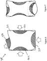
- Figure 7 shows each of these components once they have been pressed into position.
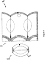
- Figure 8 shows a plan view of another blank 400 which forms a container with a tamper evident closure.
- a container formed from the blank 400 of Figure 8 is shown in Figure 17 .
- the blank 400 comprises two portions, 411 and 427.
- the first portion 411 comprises three side walls 412, 417 and 418.
- the second portion 427 comprises a base 428 for fixing to a short edge 414, 420, 422 of each side wall 412, 417, 418.
- each of the side walls 412, 417, 418 comprises a substantially curved short side 413, 419, 421 at the top end of the blank 400.
- the blank 400 forms a container with a sealed curved top end.
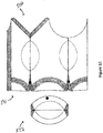
- Figures 10 and 11 show plan views of yet another blank 500 which forms a container with an open top end.
- the blank 500 comprises two portions, 511 and 527.
- the first portion 511 comprises three side walls 512, 517 and 518.
- the second portion 527 comprises a base 528 for fixing to a short edge 514, 520, 522 of each side wall 512, 517, 518.
- side wall 512 comprises two short sides 513, 544 at its top end. Short side 544, together with short side 521 of side wall 518 are scooped and form an opening when the blank 500 is assembled into a container.
- Short side 513, together with short side 519 of side wall 517 are sealed together to form a partial lid.
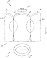
- Figures 12 and 13 show yet another blank embodiment 600 which is suitable for a container with a bottle top such as 645.
- the blank 600 comprises two portions, 611 and 627.
- the first portion 611 comprises three side walls 612, 617, 618.
- the second portion 627 comprises a base 628 which is fixable to the first portion 611
- the short sides 613, 619, 621 of each side wall 612, 617, 618 are sealed around bottle top 645 to provide a conduit from the cavity of the assembled container to the outside environment.
- the provision of a bottle top 645 improves the control of fluid into and out of the assembled container.
- the container formed from blank 600 is suitable for dispensing a pre-filled fluid rather than for filling by a user. This is particularly useful in instances such as where a sterilised fluid is contained within the container, and once evacuated cannot re-enter the container.
- Figures 14 to 17 show alternative embodiments of containers.
- Figure 14 shows a perspective view of a container 700 formed from the blank 500 of Figures 10 and 11 .
- the container 700 comprises a top end with a partial opening 739.
- the container 700 may be in its unassembled, blank configuration or may be assembled but in a 'flat' configuration where the deformable regions, such as 729, have not been disposed inwardly. Either of these configurations allows the blank/container to be transported and stored in a minimal amount of space, thereby allowing a large quantity of blanks/containers to be transported and stored at the same time.
- the deformable regions 729 are disposed inwardly to force outwards the remaining regions of the side walls, such as 712, to form a cavity within the container 700.
- Figure 15 shows another embodiment of a container 800 with another form of tamper-evident closure.
- the container 800 is provided with a bottle top 845 which is sealed between side walls, such as 812 at the top end of the container 800.
- a tamper-evident cap 846 is then provided on top of the bottle top 845.
- the cap 846 is irreversibly removable from the bottle top 845 such that when the cap 846 is removed it cannot be placed back on the container 800. A potential user can therefore easily determine whether or not the container 800 has already been used.
- the cap 846 may be pre-formed with the bottle top 845 and comprise a number of plastic bridges (not shown) between the cap 846 and the bottle top 845 which are broken with a twisting or pulling motion by a user.
- the cap 846 is fixed to the container 800 with a weak adhesive.
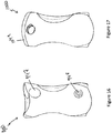
- Figure 16 shows a container 900 which further comprises a label 947 for indicating the contents or purpose of the container.
- the label may comprise a re-sealable label, thermochromic ink patch or reactive diagnostic label.
- a passage (not shown) is provided between the cavity of the container and the label 947 or a separate indicator 948, and the label/indicator provided is reactive to potential contents of the container 900.
- the label can for instance indicate the presence of pathogens, blood, pH levels or body temperature.
- a label 947 or indicator 948 can be provided which is reactive and indicates a particular colour or mark depending on the blood type which is contained.
- the label/indicator 947/948 is reactive to any fluid so that a user can determine whether or not a container 900 has already been used.
- Figure 17 shows another container 1000 with a tamper-evident closure as described with reference to Figures 8 and 9 .
- the top end 1049 of the container may comprise a weakened material such that the container 1000 is slightly ripped when opened. This will identify to a user that the container 1000 has already been used.
- Figures 18 and 19 show further embodiments of the invention, comprising containers 1100 and 1200 in the form of bowls or pans.
- a bowl 1100 is provided which is substantially flat prior to being assembled.
- the base 1128 of the bowl 1100 is located between the side walls, such as 1112.
- the base 1128 is pushed downwards as shown by arrow F1.
- Deformable portions 1129 and 1130 are also disposed inwardly, as shown by arrows E1 and E2.
- Figure 19 shows an alternative embodiment where the base 1228 of bowl 1200 is pushed upwards in use, as shown by arrow B1, to open the bowl 1200.
- disposable portions 1229 and 1230 are also disposed inwardly, as shown by arrows A1 and A2, to force out the remaining portions of the side walls, such as 1212.
- Figure 20 shows an exemplary embodiment 1300 comprising two side walls 1312, 1317 which are joined together by a base 1328 such that the or each side wall is integral with the base.
- a number of fold lines along the width of the blank 1300 allow the opposite short edges 1313, 1314 of each side wall to be brought together and optionally sealed.
- the two long edges 1315, 1316 of a first side wall 1312 each comprise an extension and the two long edges 1323, 1324 of the second side wall 1317 comprise openings to receive the extensions of the first side wall 1312 when the short edges of each side wall are brought together upon assembly into a pre-container or container.
- the side walls are generally trapezoidal, although in Figure 20 one of the edges 13 is convexly curved with respect to the main wall area.
- the base 1328 of the blank 1300 comprises three fold lines which extend across the width of the blank, thereby allowing the base 1328 to fold when the blank 1300 is assembled into a pre-container and stored in a flat configuration.
- the folding of the base, inwards towards the volume created by the blank 1300 reduces the size of the blank 1300 when it is stored pre-assembly.
- the fold which runs along the centre of the base allows the base to take a flat configuration to provide a container with improved stability.
- the base has a substantially rectangular shape to further improve stability.
- the container which is assembled from the blank is tapered from the base 1328 inwards towards the short ends 1313, 1314 of the two side walls.
- the blank further comprises one or more openings, such as 1340, to allow a user to fill the volume of the blank in use.
- the blank comprises two openings, at different positions on the blank, for use by a male or female.
- the opening configured for use by a male is preferably positioned at a greater height than the opening configured for use by a female, due to the typically larger bladders of males.
- the opening designed for a male may be smaller and the opening designed for a female may be larger to accommodate the increased difficulty for women to use a urinal.
- openings are provided at either end of the assembled container.
- the openings of the assembled container of the blank 1300 are formed by apertures at the first and second side walls.
- the extensions 1315, 1316 of the first side wall 1312 each comprise a rounded triangular aperture.
- Each end of the second side wall 1317 comprises an aperture approximately half the size of the corresponding aperture of the first side wall 1312.
- the two ends of the container comprising the apertures are caused to open up by the flattening of the base 1328 to reveal the apertures which are of a rounded triangular shape.
- the particular shape of the apertures is advantageous due to the tapered shape of the assembled container.
- a single opening is provided for use by males and females.
- the height of the opening is preferably approximately 60mm from the base of the assembled container and has a width between 80 and 95mm when the container is in its assembled form.
- the or each opening may be closed when the blank is in the blank or pre-container forms, and open when assembled into the container.
- the openings may initially be provided with a covering which is integrally formed with the rest of the blank 1300 and which has a perforated border. A user may thus push either or both of the perforated coverings into the container prior to use.
- the or each opening comprises a tongue which is preferably folded down prior to use.
- the tongue provides at least part of the perimeter of the or each opening with a soft edge to minimise the risk of discomfort or injury during use.
- the blank also further comprises one or more additional holes 1320 which are located towards one of the short edges of a side wall.
- the additional holes provide a means for the container to be carried and held in use.
- the tapered configuration of the assembled container allows the container to be straightforwardly and intuitively pinched and held.
- the blank of Figure 20 has a length between (and including) 220mm and 240mm and has a height in the range of 170mm to 195mm when assembled.
- the assembled container preferably has a fill volume of between 700ml and 900ml, and more preferably a fill volume of approximately 800ml.
- the pre-container and assembled container of the blank of Figure 20 is shown in Figures 21 and 22 .
- the base 1328 is folded in towards the inside of the pre-container.
- Deformable regions 1329, 1330 are folded outwardly to allow the pre-container to be stored and transported in a flat configuration. Pushing of the deformable regions 1329, 1330 inwards towards the centre of the pre-container (shown by the arrows in Figure 21 ) causes the two side walls to move outwardly, forming the volume to be filled within the container. Simultaneously, the base 1328 is forced outwardly.
- Figure 22 shows the assembled container of the blank of Figure 20 and the pre-container of Figure 21 .
- Each of the blanks may be formed of a waterproof card, pulp, Bagasse, or a mixture thereof, and preferably the blanks are formed of a single piece of material.
Landscapes
- Health & Medical Sciences (AREA)
- Engineering & Computer Science (AREA)
- Mechanical Engineering (AREA)
- Life Sciences & Earth Sciences (AREA)
- Animal Behavior & Ethology (AREA)
- General Health & Medical Sciences (AREA)
- Public Health (AREA)
- Veterinary Medicine (AREA)
- Pharmacology & Pharmacy (AREA)
- Hematology (AREA)
- Epidemiology (AREA)
- Packages (AREA)
Claims (14)
- Vorbehälter, im Gebrauch erweiterbar von einer flachen, gefalteten Konfiguration zu einem Behälter für Fluide, wobei der Vorbehälter einen ersten Abschnitt (11) umfasst, der eine erste Seitenwand (112) mit mindestens zwei kurzen Enden (113, 114) und zwei langen Kanten (115, 116) sowie eine zusätzliche Seitenwand (112) umfasst, wobei die zusätzliche Seitenwand mindestens zwei zusätzliche Seitenwandenden und zwei zusätzliche Seitenwandkanten aufweist, wobei die zusätzliche Seitenwand faltbar entlang einer ersten zusätzlichen Seitenwandkante an der ersten Kante (115, 116) der ersten Seitenwand angebracht ist, wobei die erste faltbare Anbringung die Form einer ersten Knickfaltlinie aufweist, sowie faltbar entlang einer weiten zusätzlichen Seitenwandkante an der zweiten Kante der ersten Seitenwand angebracht ist, wobei die zweite faltbare Anbringung die Form einer zweiten Knickfaltlinie aufweist, wobei gegenüberliegende Seiten der Seitenwände abdichtend miteinander verbunden sind, um einen kontinuierlichen Umfang zu bilden;
wobei der Vorbehälter einen Basisabschnitt (128) umfasst, der abdichtend an einem kurzen Ende (113) jeder Seitenwand befestigt ist; und
wobei der Vorbehälter ferner zwei verformbare Bereiche (129) umfasst, welche sich über die erste und die zweite Knickfaltlinie zwischen benachbarten Seitenwänden erstrecken, derart, dass der Vorbehälter bei Ausüben von Druck auf die verformbaren Bereiche zu einem Behälter mit Sanduhrform formbar ist,
wobei der Behälter (100) von vorne gesehen oben und unten breiter ist als ein mittlerer Abschnitt des Behälters, wobei der mittlere Abschnitt eine Einschnürung definiert, wobei der mittlere Abschnitt die verformbaren Bereiche (129) umfasst,
wobei nur eine Knickfaltlinie über jeden verformbaren Bereich (129) verläuft. - Vorbehälter nach Anspruch 1, wobei der Basisabschnitt an einem Ende der oder jeder Seitenwand mit einem Kleber befestigt ist.
- Behälter (100) zur Fluidaufbewahrung, wobei der Behälter aus dem Vorbehälter von Anspruch 1 oder 2 gebildet ist,
wobei der Behälter zwei Seitenwände (112) umfasst, wobei jede Seitenwand mindestens zwei Enden (113, 114) und zwei Kanten (115, 116) aufweist, wobei die Seitenwände entlang jeder ihrer gegenüberliegenden Kanten über eine erste Knickfaltlinie und eine zweite Knickfaltlinie miteinander verbunden sind, um einen kontinuierlichen Umfang zu bilden, der einen Durchgang definiert;
wobei der Behälter ferner eine Basis (128) aufweist, die an einem kurzen Ende (114) jeder Seitenwand um den kontinuierlichen Umfang herum befestigt ist; und wobei sich zwischen den Enden (113) jeder nicht an der Basis befestigten Seitenwand eine Öffnung (139) befindet; wobei der Behälter ferner zwei verformbare Bereiche (129) umfasst, welche sich zumindest teilweise über die erste und die zweite Faltlinie zwischen benachbarten Seitenwänden erstrecken; wobei die verformbaren Bereiche nach innen in Richtung der Mitte des definierten Durchgangs gedrückt sind, derart, dass eine Kavität gebildet ist,
wobei der Behälter eine Sanduhrform aufweist, wobei der Behälter (100) von vorne gesehen oben und unten breiter ist als ein mittlerer Abschnitt des Behälters, wobei der mittlere Abschnitt eine Einschnürung definiert, wobei der mittlere Abschnitt die verformbaren Bereiche (129) umfasst, wobei nur eine Knickfaltlinie über jeden verformbaren Bereich (129) verläuft. - Behälter nach Anspruch 3, umfassend einen Deckel, der nur teilweise um den kontinuierlichen Umfang herum an einem nicht an der Basis befestigten Ende des Behälters befestigt ist, derart, dass eine Öffnung beibehalten ist, wo der Deckel nicht befestigt ist.
- Behälter nach einem der Ansprüche 3 oder 4, wobei der Behälter ferner einen oder mehrere Stege umfasst, die sich zumindest teilweise entlang der Verbindungen zwischen jeder Seitenwand befinden, wobei sich ein Steg entlang eines Abschnitts jeder Verbindung zwischen Seitenwänden neben dem Basisende des Behälters befindet und sich ein zusätzlicher Steg entlang eines Abschnitts einer Verbindung zwischen Seitenwänden neben dem Deckelende des Behälters befindet.
- Behälter nach einem der Ansprüche 3 bis 5, wobei der Behälter ferner einen Flaschenhals umfasst, der in der Öffnung zwischen den nicht an der Basis befestigten Enden jeder Seitenwand positioniert ist.
- Zuschnitt (10) zum Herstellen eines Vorbehälters (100) nach Anspruch 1, wobei der Zuschnitt einen ersten Abschnitt (11) umfasst, der eine erste Seitenwand (12) mit mindestens zwei kurzen Enden (13, 14) und zwei langen Kanten (15, 16) sowie mindestens zwei zusätzliche Seitenwände (17, 18) umfasst, die sich von einer Kante der ersten Seitenwand erstrecken, wobei jede zusätzliche Seitenwand zwei zusätzliche kurze Seitenwandenden (19, 20, 21, 22) und zwei zusätzliche lange Seitenwandkanten (23, 24, 25, 26) aufweist;
wobei der Zuschnitt einen zweiten Abschnitt umfasst, der eine Basis (28) umfasst, die an einem kurzen Ende (14, 20, 22) der oder jeder Seitenwand befestigbar ist; wobei die Verbindungen zwischen den zusätzlichen Seitenwänden und der ersten Seitenwand Knickfalten umfassen; und
wobei der Zuschnitt ferner eine Anzahl von verformbaren Bereichen (29, 30) umfasst, die sich zumindest teilweise über die Knickfalten zwischen den zusätzlichen Seitenwänden und der ersten Seitenwand erstrecken, wobei der Zuschnitt einen zusammengesetzten Behälter mit einer Sanduhrform bilden kann,
wobei der Behälter (100) von vorne gesehen oben und unten breiter ist ein mittlerer Abschnitt des Behälters, wobei der mittlere Abschnitt eine Einschnürung definiert;
wobei der mittlere Abschnitt die verformbaren Bereiche (29, 30) umfasst, wenn die Kanten (23, 26) der zusätzlichen Seitenwände, die nicht mit einer anderen Seitenwandkante verbunden sind, nahe zueinander gebracht und verbunden werden, um eine einzelne zusätzliche Seitenwand zu bilden, wobei die Basis an einem kurzen Ende jeder Seitenwand befestigt ist und die verformbaren Bereiche nach innen angeordnet sind, derart, dass in dem zusammengesetzten Behälter eine Kavität gebildet ist. - Zuschnitt (10) zum Herstellen eines Vorbehälters (100) nach Anspruch 1, wobei der Zuschnitt eine erste Seitenwand (12) mit mindestens zwei kurzen Enden (13, 14) und zwei langen Kanten (15, 16) sowie mindestens zwei zusätzliche Seitenwände (17, 18) umfasst, die sich von einer Kante der ersten Seitenwand erstrecken, wobei jede zusätzliche Seitenwand mindestens zwei zusätzliche kurze Seitenwandenden (19, 20, 21, 22) und zwei zusätzliche lange Seitenwandkanten (23, 24, 25, 26) aufweist; sowie eine Basis (28) umfasst, die von einem kurzen Ende einer der Seitenwände verläuft;
wobei die Verbindungen zwischen den Seitenwänden und der Basis eine Knickfalte umfassen; und
wobei die Verbindungen zwischen den zusätzlichen Seitenwänden und der ersten Seitenwand Knickfalten umfassen;
wobei der Zuschnitt ferner eine Anzahl von verformbaren Bereichen (29, 30) umfasst, die sich zumindest teilweise über die Verbindungen zwischen jeder Seitenwand erstrecken, wobei der Zuschnitt einen zusammengesetzten Behälter mit einer Sanduhrform bilden kann, wobei der Behälter (100) von vorne gesehen oben und unten breiter ist als ein mittlerer Abschnitt des Behälters,
wobei der mittlere Abschnitt eine Einschnürung definiert, wobei der mittlere Abschnitt die verformbaren Bereiche (29, 30) umfasst, wenn die Kanten der zusätzlichen Seitenwände (23, 26), die nicht mit einer anderen Seitenwandkante verbunden sind, nahe zueinander gebracht und befestigt werden, um eine einzelne zusätzliche Seitenwand zu bilden, wenn die Basis gefaltet und nahe an jede Seitenwand gebracht wird, und wobei die verformbaren Bereiche nach innen angeordnet sind, derart, dass in dem zusammengesetzten Behälter eine Kavität gebildet ist. - Zuschnitt nach Anspruch 7 oder Anspruch 8, wobei der Zuschnitt ferner einen Deckel umfasst, der sich von einem Ende einer der Seitenwände aus erstreckt.
- Zuschnitt nach einem der Ansprüche 7 bis 9, wobei sich der Deckel und die Basis an gegenüberliegenden Enden der ersten Seitenwand befinden, wenn der Zuschnitt zusammengesetzt ist.
- Zuschnitt nach einem der Ansprüche 7 bis 10, wobei die Seitenwände im Wesentlichen rechteckig geformt sind oder wobei die Seitenwände im Wesentlichen trapezförmig sind.
- Verfahren zum Herstellen eines Behälters (100) zur Fluidaufbewahrung, wobei das Verfahren die folgenden Schritte umfasst:- Bereitstellen eines Zuschnitts (10), der im zusammengesetzten Zustand einen Behälter bildet;- Falten des Zuschnitts entlang zweier Faltlinien über die Breite des Zuschnitts, um eine allgemein rechteckige oder trapezförmige Seitenwand (12) und zwei zusätzliche Seitenwände (17, 18) zu bilden, derart, dass die erste und die zweite gegenüberliegende lange Seite (23, 26) der beiden zusätzlichen Seitenwände nahe zueinander gebracht werden;- Verbinden der ersten und der zweiten langen Seite (23, 26) der zusätzlichen Seitenwände miteinander, wobei eine kontinuierliche Seitenwand umfassend zwei Knickfaltlinien gebildet wird;- Verformen einer oder mehrerer verformbarer Bereiche (129), die sich über die Knickfaltlinien erstrecken, derart, dass die verformbaren Bereiche nach innen angeordnet werden, um den Rest der Seitenwand nach außen zu drücken, um eine Öffnung innerhalb des Zuschnitts zu erzeugen; und- Verschließen einer Basis (28) um den Umfang eines ersten kurzen Endes (14) der Seitenwand, wobei der Behälter an den verformbaren Bereichen eine Breite hat, die kleiner ist als eine Breite des Behälters über und unter den verformbaren Bereichen, wobei der Behälter (100) von vorne gesehen oben und unten breiter ist ein mittlerer Abschnitt des Behälters, wobei der mittlere Abschnitt eine Einschnürung definiert, wobei der mittlere Abschnitt die verformbaren Bereiche (129) umfasst.
- Verfahren nach Anspruch 12, wobei der Schritt des Faltens des Zuschnitts entlang einer oder mehrerer Faltlinien über die Breite des Zuschnitts eine trapezförmige Seitenwand bildet und wobei mindestens eine Kante der Seitenwand gebogen ist.
- Verfahren nach einem der Ansprüche 12 bis 13, wobei die erste und die zweite Kante der Seitenwand im Wesentlichen einander gegenüber liegen.
Applications Claiming Priority (2)
| Application Number | Priority Date | Filing Date | Title |
|---|---|---|---|
| GBGB1512926.5A GB201512926D0 (en) | 2015-07-22 | 2015-07-22 | Methods of manufacture of containers, pre-containers, blanks for containers and containers for retaining fluids |
| PCT/GB2016/052245 WO2017013446A1 (en) | 2015-07-22 | 2016-07-22 | Methods of manufacture of containers, pre-containers, blanks for containers and containers for retaining fluids |
Publications (2)
| Publication Number | Publication Date |
|---|---|
| EP3325359A1 EP3325359A1 (de) | 2018-05-30 |
| EP3325359B1 true EP3325359B1 (de) | 2021-03-17 |
Family
ID=54064778
Family Applications (1)
| Application Number | Title | Priority Date | Filing Date |
|---|---|---|---|
| EP16753417.1A Active EP3325359B1 (de) | 2015-07-22 | 2016-07-22 | Verfahren zur herstellung von behältern, vorbehälter, zuschnitte für behälter und behälter zur aufnahme von flüssigkeiten |
Country Status (5)
| Country | Link |
|---|---|
| US (1) | US10934071B2 (de) |
| EP (1) | EP3325359B1 (de) |
| CN (1) | CN108349622B (de) |
| GB (1) | GB201512926D0 (de) |
| WO (1) | WO2017013446A1 (de) |
Families Citing this family (3)
| Publication number | Priority date | Publication date | Assignee | Title |
|---|---|---|---|---|
| EP3366223B1 (de) * | 2017-02-24 | 2019-05-01 | Protzek Gesellschaft für Biomedizinische Technik GmbH | Laborbecher |
| NL2021396B1 (en) * | 2018-07-26 | 2020-01-31 | Hygienius Intellectual Property B V | Container |
| US11028567B2 (en) * | 2019-04-19 | 2021-06-08 | Kohler Co. | Plumbing fixture with drain-casted jet orifice |
Citations (1)
| Publication number | Priority date | Publication date | Assignee | Title |
|---|---|---|---|---|
| KR20150011948A (ko) * | 2013-07-24 | 2015-02-03 | 이민진 | 커피믹스를 구비한 접이식 종이컵 |
Family Cites Families (7)
| Publication number | Priority date | Publication date | Assignee | Title |
|---|---|---|---|---|
| GB1030542A (en) * | 1964-01-29 | 1966-05-25 | Reed Paper Group Ltd | Improvements in or relating to bed bottles |
| JPS63123421U (de) * | 1987-02-04 | 1988-08-11 | ||
| CN2084454U (zh) * | 1989-04-19 | 1991-09-11 | 马奇诺尼·吉奥达诺 | 容器 |
| ATE263062T1 (de) * | 1995-05-23 | 2004-04-15 | Easycarton Ltd | Behälter |
| US20120008884A1 (en) * | 2007-04-03 | 2012-01-12 | Pouch Pac Innovations, Llc | Stand-up flexible pouch and method of forming |
| GB0802518D0 (en) * | 2008-02-12 | 2008-03-19 | Elopak Systems | Container made of material, blank and methods |
| GB201319433D0 (en) | 2013-11-04 | 2013-12-18 | Vernacare Ltd | Container |
-
2015
- 2015-07-22 GB GBGB1512926.5A patent/GB201512926D0/en not_active Ceased
-
2016
- 2016-07-22 CN CN201680042975.8A patent/CN108349622B/zh not_active Expired - Fee Related
- 2016-07-22 EP EP16753417.1A patent/EP3325359B1/de active Active
- 2016-07-22 US US15/746,361 patent/US10934071B2/en not_active Expired - Fee Related
- 2016-07-22 WO PCT/GB2016/052245 patent/WO2017013446A1/en not_active Ceased
Patent Citations (1)
| Publication number | Priority date | Publication date | Assignee | Title |
|---|---|---|---|---|
| KR20150011948A (ko) * | 2013-07-24 | 2015-02-03 | 이민진 | 커피믹스를 구비한 접이식 종이컵 |
Also Published As
| Publication number | Publication date |
|---|---|
| CN108349622A (zh) | 2018-07-31 |
| GB201512926D0 (en) | 2015-09-02 |
| US10934071B2 (en) | 2021-03-02 |
| WO2017013446A1 (en) | 2017-01-26 |
| US20180215519A1 (en) | 2018-08-02 |
| EP3325359A1 (de) | 2018-05-30 |
| CN108349622B (zh) | 2021-01-26 |
Similar Documents
| Publication | Publication Date | Title |
|---|---|---|
| US8869318B2 (en) | Bedpan having a handle defined therein | |
| US20210121621A1 (en) | Packaging for Medical Containers | |
| US20170105707A1 (en) | Sample collector | |
| US10111739B2 (en) | Method for rehydration of lyophilized biologic materials | |
| US4496354A (en) | Drainage bag assembly with drip tray | |
| US6648217B2 (en) | Spill-proof disposable cup with integral sealing flap | |
| BR122013014600A2 (pt) | Copo com bico para manter e dispensar substâncias | |
| CN110381782B (zh) | 一次性可扩张液体容器和坯料 | |
| US20100094238A1 (en) | Biodegradable tampon disposal bag | |
| US10934071B2 (en) | Methods of manufacture of containers, pre-containers, blanks for containers and containers for retaining fluids | |
| BRPI0507247B1 (pt) | recipiente re-lacrável cônico reforçado | |
| BR112020020182B1 (pt) | Embalagem reforçada, peça em bruto de caixa de papelão e um saco em combinação para formar uma embalagem reforçada para reter um produto, e método para formar uma embalagem reforçada | |
| JP2010508219A (ja) | 四角形の平面状のベースを有する折り畳み可能な容器 | |
| US20180185227A1 (en) | Disposable bag for the collection of urine, vomit, and others | |
| EP2878286A1 (de) | Tragbarer behälter zur aufnahme von flüssigkeiten und zum urinieren, insbesondere für frauen | |
| NL2021396B1 (en) | Container | |
| WO2020111959A1 (en) | Stool collection device | |
| JP4382264B2 (ja) | 消毒用衛生材料収納容器 | |
| CN219354168U (zh) | 一种折叠式医疗器械无菌收纳盒 | |
| CN222743218U (zh) | 一种免接触直吸管、弯吸管连接包装袋及包装盒 | |
| WO2016005986A1 (en) | Disposable plastic tube for feeding babies | |
| JPH04135417U (ja) | 収納用紙箱の簡易開封構造 |
Legal Events
| Date | Code | Title | Description |
|---|---|---|---|
| STAA | Information on the status of an ep patent application or granted ep patent |
Free format text: STATUS: THE INTERNATIONAL PUBLICATION HAS BEEN MADE |
|
| PUAI | Public reference made under article 153(3) epc to a published international application that has entered the european phase |
Free format text: ORIGINAL CODE: 0009012 |
|
| STAA | Information on the status of an ep patent application or granted ep patent |
Free format text: STATUS: REQUEST FOR EXAMINATION WAS MADE |
|
| 17P | Request for examination filed |
Effective date: 20180215 |
|
| AK | Designated contracting states |
Kind code of ref document: A1 Designated state(s): AL AT BE BG CH CY CZ DE DK EE ES FI FR GB GR HR HU IE IS IT LI LT LU LV MC MK MT NL NO PL PT RO RS SE SI SK SM TR |
|
| AX | Request for extension of the european patent |
Extension state: BA ME |
|
| DAV | Request for validation of the european patent (deleted) | ||
| DAX | Request for extension of the european patent (deleted) | ||
| STAA | Information on the status of an ep patent application or granted ep patent |
Free format text: STATUS: EXAMINATION IS IN PROGRESS |
|
| 17Q | First examination report despatched |
Effective date: 20181212 |
|
| REG | Reference to a national code |
Ref country code: DE Ref legal event code: R079 Ref document number: 602016054432 Country of ref document: DE Free format text: PREVIOUS MAIN CLASS: B65D0005020000 Ipc: A61J0001050000 |
|
| GRAP | Despatch of communication of intention to grant a patent |
Free format text: ORIGINAL CODE: EPIDOSNIGR1 |
|
| STAA | Information on the status of an ep patent application or granted ep patent |
Free format text: STATUS: GRANT OF PATENT IS INTENDED |
|
| RIC1 | Information provided on ipc code assigned before grant |
Ipc: A61J 1/14 20060101ALI20201015BHEP Ipc: B65D 75/58 20060101ALI20201015BHEP Ipc: A61J 1/05 20060101AFI20201015BHEP Ipc: B65D 75/00 20060101ALI20201015BHEP |
|
| INTG | Intention to grant announced |
Effective date: 20201113 |
|
| GRAS | Grant fee paid |
Free format text: ORIGINAL CODE: EPIDOSNIGR3 |
|
| GRAA | (expected) grant |
Free format text: ORIGINAL CODE: 0009210 |
|
| STAA | Information on the status of an ep patent application or granted ep patent |
Free format text: STATUS: THE PATENT HAS BEEN GRANTED |
|
| AK | Designated contracting states |
Kind code of ref document: B1 Designated state(s): AL AT BE BG CH CY CZ DE DK EE ES FI FR GB GR HR HU IE IS IT LI LT LU LV MC MK MT NL NO PL PT RO RS SE SI SK SM TR |
|
| REG | Reference to a national code |
Ref country code: GB Ref legal event code: FG4D |
|
| REG | Reference to a national code |
Ref country code: CH Ref legal event code: EP |
|
| REG | Reference to a national code |
Ref country code: DE Ref legal event code: R096 Ref document number: 602016054432 Country of ref document: DE |
|
| REG | Reference to a national code |
Ref country code: IE Ref legal event code: FG4D |
|
| REG | Reference to a national code |
Ref country code: AT Ref legal event code: REF Ref document number: 1371558 Country of ref document: AT Kind code of ref document: T Effective date: 20210415 |
|
| REG | Reference to a national code |
Ref country code: CH Ref legal event code: NV Representative=s name: SAEGER AND PARTNER PATENT- UND RECHTSANWAELTE, CH |
|
| REG | Reference to a national code |
Ref country code: NL Ref legal event code: FP |
|
| REG | Reference to a national code |
Ref country code: LT Ref legal event code: MG9D |
|
| PG25 | Lapsed in a contracting state [announced via postgrant information from national office to epo] |
Ref country code: FI Free format text: LAPSE BECAUSE OF FAILURE TO SUBMIT A TRANSLATION OF THE DESCRIPTION OR TO PAY THE FEE WITHIN THE PRESCRIBED TIME-LIMIT Effective date: 20210317 Ref country code: GR Free format text: LAPSE BECAUSE OF FAILURE TO SUBMIT A TRANSLATION OF THE DESCRIPTION OR TO PAY THE FEE WITHIN THE PRESCRIBED TIME-LIMIT Effective date: 20210618 Ref country code: HR Free format text: LAPSE BECAUSE OF FAILURE TO SUBMIT A TRANSLATION OF THE DESCRIPTION OR TO PAY THE FEE WITHIN THE PRESCRIBED TIME-LIMIT Effective date: 20210317 Ref country code: NO Free format text: LAPSE BECAUSE OF FAILURE TO SUBMIT A TRANSLATION OF THE DESCRIPTION OR TO PAY THE FEE WITHIN THE PRESCRIBED TIME-LIMIT Effective date: 20210617 Ref country code: BG Free format text: LAPSE BECAUSE OF FAILURE TO SUBMIT A TRANSLATION OF THE DESCRIPTION OR TO PAY THE FEE WITHIN THE PRESCRIBED TIME-LIMIT Effective date: 20210617 |
|
| REG | Reference to a national code |
Ref country code: AT Ref legal event code: MK05 Ref document number: 1371558 Country of ref document: AT Kind code of ref document: T Effective date: 20210317 |
|
| PG25 | Lapsed in a contracting state [announced via postgrant information from national office to epo] |
Ref country code: LV Free format text: LAPSE BECAUSE OF FAILURE TO SUBMIT A TRANSLATION OF THE DESCRIPTION OR TO PAY THE FEE WITHIN THE PRESCRIBED TIME-LIMIT Effective date: 20210317 Ref country code: RS Free format text: LAPSE BECAUSE OF FAILURE TO SUBMIT A TRANSLATION OF THE DESCRIPTION OR TO PAY THE FEE WITHIN THE PRESCRIBED TIME-LIMIT Effective date: 20210317 Ref country code: SE Free format text: LAPSE BECAUSE OF FAILURE TO SUBMIT A TRANSLATION OF THE DESCRIPTION OR TO PAY THE FEE WITHIN THE PRESCRIBED TIME-LIMIT Effective date: 20210317 |
|
| PG25 | Lapsed in a contracting state [announced via postgrant information from national office to epo] |
Ref country code: EE Free format text: LAPSE BECAUSE OF FAILURE TO SUBMIT A TRANSLATION OF THE DESCRIPTION OR TO PAY THE FEE WITHIN THE PRESCRIBED TIME-LIMIT Effective date: 20210317 Ref country code: CZ Free format text: LAPSE BECAUSE OF FAILURE TO SUBMIT A TRANSLATION OF THE DESCRIPTION OR TO PAY THE FEE WITHIN THE PRESCRIBED TIME-LIMIT Effective date: 20210317 Ref country code: LT Free format text: LAPSE BECAUSE OF FAILURE TO SUBMIT A TRANSLATION OF THE DESCRIPTION OR TO PAY THE FEE WITHIN THE PRESCRIBED TIME-LIMIT Effective date: 20210317 Ref country code: AT Free format text: LAPSE BECAUSE OF FAILURE TO SUBMIT A TRANSLATION OF THE DESCRIPTION OR TO PAY THE FEE WITHIN THE PRESCRIBED TIME-LIMIT Effective date: 20210317 Ref country code: SM Free format text: LAPSE BECAUSE OF FAILURE TO SUBMIT A TRANSLATION OF THE DESCRIPTION OR TO PAY THE FEE WITHIN THE PRESCRIBED TIME-LIMIT Effective date: 20210317 |
|
| PG25 | Lapsed in a contracting state [announced via postgrant information from national office to epo] |
Ref country code: SK Free format text: LAPSE BECAUSE OF FAILURE TO SUBMIT A TRANSLATION OF THE DESCRIPTION OR TO PAY THE FEE WITHIN THE PRESCRIBED TIME-LIMIT Effective date: 20210317 Ref country code: IS Free format text: LAPSE BECAUSE OF FAILURE TO SUBMIT A TRANSLATION OF THE DESCRIPTION OR TO PAY THE FEE WITHIN THE PRESCRIBED TIME-LIMIT Effective date: 20210717 Ref country code: PT Free format text: LAPSE BECAUSE OF FAILURE TO SUBMIT A TRANSLATION OF THE DESCRIPTION OR TO PAY THE FEE WITHIN THE PRESCRIBED TIME-LIMIT Effective date: 20210719 Ref country code: PL Free format text: LAPSE BECAUSE OF FAILURE TO SUBMIT A TRANSLATION OF THE DESCRIPTION OR TO PAY THE FEE WITHIN THE PRESCRIBED TIME-LIMIT Effective date: 20210317 Ref country code: RO Free format text: LAPSE BECAUSE OF FAILURE TO SUBMIT A TRANSLATION OF THE DESCRIPTION OR TO PAY THE FEE WITHIN THE PRESCRIBED TIME-LIMIT Effective date: 20210317 |
|
| REG | Reference to a national code |
Ref country code: DE Ref legal event code: R097 Ref document number: 602016054432 Country of ref document: DE |
|
| PLBE | No opposition filed within time limit |
Free format text: ORIGINAL CODE: 0009261 |
|
| STAA | Information on the status of an ep patent application or granted ep patent |
Free format text: STATUS: NO OPPOSITION FILED WITHIN TIME LIMIT |
|
| PG25 | Lapsed in a contracting state [announced via postgrant information from national office to epo] |
Ref country code: AL Free format text: LAPSE BECAUSE OF FAILURE TO SUBMIT A TRANSLATION OF THE DESCRIPTION OR TO PAY THE FEE WITHIN THE PRESCRIBED TIME-LIMIT Effective date: 20210317 Ref country code: ES Free format text: LAPSE BECAUSE OF FAILURE TO SUBMIT A TRANSLATION OF THE DESCRIPTION OR TO PAY THE FEE WITHIN THE PRESCRIBED TIME-LIMIT Effective date: 20210317 Ref country code: DK Free format text: LAPSE BECAUSE OF FAILURE TO SUBMIT A TRANSLATION OF THE DESCRIPTION OR TO PAY THE FEE WITHIN THE PRESCRIBED TIME-LIMIT Effective date: 20210317 |
|
| 26N | No opposition filed |
Effective date: 20211220 |
|
| PG25 | Lapsed in a contracting state [announced via postgrant information from national office to epo] |
Ref country code: SI Free format text: LAPSE BECAUSE OF FAILURE TO SUBMIT A TRANSLATION OF THE DESCRIPTION OR TO PAY THE FEE WITHIN THE PRESCRIBED TIME-LIMIT Effective date: 20210317 |
|
| PG25 | Lapsed in a contracting state [announced via postgrant information from national office to epo] |
Ref country code: MC Free format text: LAPSE BECAUSE OF FAILURE TO SUBMIT A TRANSLATION OF THE DESCRIPTION OR TO PAY THE FEE WITHIN THE PRESCRIBED TIME-LIMIT Effective date: 20210317 |
|
| PG25 | Lapsed in a contracting state [announced via postgrant information from national office to epo] |
Ref country code: IT Free format text: LAPSE BECAUSE OF FAILURE TO SUBMIT A TRANSLATION OF THE DESCRIPTION OR TO PAY THE FEE WITHIN THE PRESCRIBED TIME-LIMIT Effective date: 20210317 |
|
| PG25 | Lapsed in a contracting state [announced via postgrant information from national office to epo] |
Ref country code: IS Free format text: LAPSE BECAUSE OF FAILURE TO SUBMIT A TRANSLATION OF THE DESCRIPTION OR TO PAY THE FEE WITHIN THE PRESCRIBED TIME-LIMIT Effective date: 20210717 Ref country code: LU Free format text: LAPSE BECAUSE OF NON-PAYMENT OF DUE FEES Effective date: 20210722 |
|
| PG25 | Lapsed in a contracting state [announced via postgrant information from national office to epo] |
Ref country code: IE Free format text: LAPSE BECAUSE OF NON-PAYMENT OF DUE FEES Effective date: 20210722 |
|
| PG25 | Lapsed in a contracting state [announced via postgrant information from national office to epo] |
Ref country code: HU Free format text: LAPSE BECAUSE OF FAILURE TO SUBMIT A TRANSLATION OF THE DESCRIPTION OR TO PAY THE FEE WITHIN THE PRESCRIBED TIME-LIMIT; INVALID AB INITIO Effective date: 20160722 |
|
| P01 | Opt-out of the competence of the unified patent court (upc) registered |
Effective date: 20230522 |
|
| PG25 | Lapsed in a contracting state [announced via postgrant information from national office to epo] |
Ref country code: CY Free format text: LAPSE BECAUSE OF FAILURE TO SUBMIT A TRANSLATION OF THE DESCRIPTION OR TO PAY THE FEE WITHIN THE PRESCRIBED TIME-LIMIT Effective date: 20210317 |
|
| PGFP | Annual fee paid to national office [announced via postgrant information from national office to epo] |
Ref country code: NL Payment date: 20230724 Year of fee payment: 8 |
|
| PGFP | Annual fee paid to national office [announced via postgrant information from national office to epo] |
Ref country code: GB Payment date: 20230724 Year of fee payment: 8 Ref country code: CH Payment date: 20230801 Year of fee payment: 8 |
|
| PGFP | Annual fee paid to national office [announced via postgrant information from national office to epo] |
Ref country code: FR Payment date: 20230724 Year of fee payment: 8 Ref country code: DE Payment date: 20230720 Year of fee payment: 8 Ref country code: BE Payment date: 20230721 Year of fee payment: 8 |
|
| PG25 | Lapsed in a contracting state [announced via postgrant information from national office to epo] |
Ref country code: MK Free format text: LAPSE BECAUSE OF FAILURE TO SUBMIT A TRANSLATION OF THE DESCRIPTION OR TO PAY THE FEE WITHIN THE PRESCRIBED TIME-LIMIT Effective date: 20210317 |
|
| PG25 | Lapsed in a contracting state [announced via postgrant information from national office to epo] |
Ref country code: TR Free format text: LAPSE BECAUSE OF FAILURE TO SUBMIT A TRANSLATION OF THE DESCRIPTION OR TO PAY THE FEE WITHIN THE PRESCRIBED TIME-LIMIT Effective date: 20210317 |
|
| PG25 | Lapsed in a contracting state [announced via postgrant information from national office to epo] |
Ref country code: MT Free format text: LAPSE BECAUSE OF FAILURE TO SUBMIT A TRANSLATION OF THE DESCRIPTION OR TO PAY THE FEE WITHIN THE PRESCRIBED TIME-LIMIT Effective date: 20210317 |
|
| REG | Reference to a national code |
Ref country code: DE Ref legal event code: R119 Ref document number: 602016054432 Country of ref document: DE |
|
| REG | Reference to a national code |
Ref country code: CH Ref legal event code: PL |
|
| REG | Reference to a national code |
Ref country code: NL Ref legal event code: MM Effective date: 20240801 |
|
| GBPC | Gb: european patent ceased through non-payment of renewal fee |
Effective date: 20240722 |
|
| PG25 | Lapsed in a contracting state [announced via postgrant information from national office to epo] |
Ref country code: DE Free format text: LAPSE BECAUSE OF NON-PAYMENT OF DUE FEES Effective date: 20250201 |
|
| PG25 | Lapsed in a contracting state [announced via postgrant information from national office to epo] |
Ref country code: NL Free format text: LAPSE BECAUSE OF NON-PAYMENT OF DUE FEES Effective date: 20240801 |
|
| PG25 | Lapsed in a contracting state [announced via postgrant information from national office to epo] |
Ref country code: CH Free format text: LAPSE BECAUSE OF NON-PAYMENT OF DUE FEES Effective date: 20240731 Ref country code: BE Free format text: LAPSE BECAUSE OF NON-PAYMENT OF DUE FEES Effective date: 20240731 |
|
| PG25 | Lapsed in a contracting state [announced via postgrant information from national office to epo] |
Ref country code: FR Free format text: LAPSE BECAUSE OF NON-PAYMENT OF DUE FEES Effective date: 20240731 |
|
| PG25 | Lapsed in a contracting state [announced via postgrant information from national office to epo] |
Ref country code: GB Free format text: LAPSE BECAUSE OF NON-PAYMENT OF DUE FEES Effective date: 20240722 |
|
| REG | Reference to a national code |
Ref country code: BE Ref legal event code: MM Effective date: 20240731 |