EP3324464A1 - Roll electrode and method for manufacturing roll electrode - Google Patents
Roll electrode and method for manufacturing roll electrode Download PDFInfo
- Publication number
- EP3324464A1 EP3324464A1 EP15898303.1A EP15898303A EP3324464A1 EP 3324464 A1 EP3324464 A1 EP 3324464A1 EP 15898303 A EP15898303 A EP 15898303A EP 3324464 A1 EP3324464 A1 EP 3324464A1
- Authority
- EP
- European Patent Office
- Prior art keywords
- electrode
- core
- winding
- roll
- outer circumference
- Prior art date
- Legal status (The legal status is an assumption and is not a legal conclusion. Google has not performed a legal analysis and makes no representation as to the accuracy of the status listed.)
- Pending
Links
Images


Classifications
-
- H—ELECTRICITY
- H01—ELECTRIC ELEMENTS
- H01M—PROCESSES OR MEANS, e.g. BATTERIES, FOR THE DIRECT CONVERSION OF CHEMICAL ENERGY INTO ELECTRICAL ENERGY
- H01M4/00—Electrodes
- H01M4/02—Electrodes composed of, or comprising, active material
- H01M4/13—Electrodes for accumulators with non-aqueous electrolyte, e.g. for lithium-accumulators; Processes of manufacture thereof
- H01M4/139—Processes of manufacture
- H01M4/1393—Processes of manufacture of electrodes based on carbonaceous material, e.g. graphite-intercalation compounds or CFx
-
- H—ELECTRICITY
- H01—ELECTRIC ELEMENTS
- H01M—PROCESSES OR MEANS, e.g. BATTERIES, FOR THE DIRECT CONVERSION OF CHEMICAL ENERGY INTO ELECTRICAL ENERGY
- H01M4/00—Electrodes
- H01M4/02—Electrodes composed of, or comprising, active material
-
- B—PERFORMING OPERATIONS; TRANSPORTING
- B65—CONVEYING; PACKING; STORING; HANDLING THIN OR FILAMENTARY MATERIAL
- B65H—HANDLING THIN OR FILAMENTARY MATERIAL, e.g. SHEETS, WEBS, CABLES
- B65H18/00—Winding webs
- B65H18/08—Web-winding mechanisms
-
- H—ELECTRICITY
- H01—ELECTRIC ELEMENTS
- H01M—PROCESSES OR MEANS, e.g. BATTERIES, FOR THE DIRECT CONVERSION OF CHEMICAL ENERGY INTO ELECTRICAL ENERGY
- H01M10/00—Secondary cells; Manufacture thereof
- H01M10/04—Construction or manufacture in general
- H01M10/0431—Cells with wound or folded electrodes
-
- H—ELECTRICITY
- H01—ELECTRIC ELEMENTS
- H01M—PROCESSES OR MEANS, e.g. BATTERIES, FOR THE DIRECT CONVERSION OF CHEMICAL ENERGY INTO ELECTRICAL ENERGY
- H01M10/00—Secondary cells; Manufacture thereof
- H01M10/05—Accumulators with non-aqueous electrolyte
- H01M10/052—Li-accumulators
-
- H—ELECTRICITY
- H01—ELECTRIC ELEMENTS
- H01M—PROCESSES OR MEANS, e.g. BATTERIES, FOR THE DIRECT CONVERSION OF CHEMICAL ENERGY INTO ELECTRICAL ENERGY
- H01M10/00—Secondary cells; Manufacture thereof
- H01M10/05—Accumulators with non-aqueous electrolyte
- H01M10/058—Construction or manufacture
- H01M10/0587—Construction or manufacture of accumulators having only wound construction elements, i.e. wound positive electrodes, wound negative electrodes and wound separators
-
- H—ELECTRICITY
- H01—ELECTRIC ELEMENTS
- H01M—PROCESSES OR MEANS, e.g. BATTERIES, FOR THE DIRECT CONVERSION OF CHEMICAL ENERGY INTO ELECTRICAL ENERGY
- H01M4/00—Electrodes
- H01M4/02—Electrodes composed of, or comprising, active material
- H01M4/04—Processes of manufacture in general
-
- H—ELECTRICITY
- H01—ELECTRIC ELEMENTS
- H01M—PROCESSES OR MEANS, e.g. BATTERIES, FOR THE DIRECT CONVERSION OF CHEMICAL ENERGY INTO ELECTRICAL ENERGY
- H01M4/00—Electrodes
- H01M4/02—Electrodes composed of, or comprising, active material
- H01M4/13—Electrodes for accumulators with non-aqueous electrolyte, e.g. for lithium-accumulators; Processes of manufacture thereof
- H01M4/139—Processes of manufacture
- H01M4/1395—Processes of manufacture of electrodes based on metals, Si or alloys
-
- H—ELECTRICITY
- H01—ELECTRIC ELEMENTS
- H01M—PROCESSES OR MEANS, e.g. BATTERIES, FOR THE DIRECT CONVERSION OF CHEMICAL ENERGY INTO ELECTRICAL ENERGY
- H01M4/00—Electrodes
- H01M4/02—Electrodes composed of, or comprising, active material
- H01M4/64—Carriers or collectors
- H01M4/66—Selection of materials
- H01M4/661—Metal or alloys, e.g. alloy coatings
-
- H—ELECTRICITY
- H01—ELECTRIC ELEMENTS
- H01M—PROCESSES OR MEANS, e.g. BATTERIES, FOR THE DIRECT CONVERSION OF CHEMICAL ENERGY INTO ELECTRICAL ENERGY
- H01M4/00—Electrodes
- H01M4/02—Electrodes composed of, or comprising, active material
- H01M4/64—Carriers or collectors
- H01M4/70—Carriers or collectors characterised by shape or form
-
- B—PERFORMING OPERATIONS; TRANSPORTING
- B65—CONVEYING; PACKING; STORING; HANDLING THIN OR FILAMENTARY MATERIAL
- B65H—HANDLING THIN OR FILAMENTARY MATERIAL, e.g. SHEETS, WEBS, CABLES
- B65H2301/00—Handling processes for sheets or webs
- B65H2301/40—Type of handling process
- B65H2301/41—Winding, unwinding
- B65H2301/414—Winding
- B65H2301/41419—Starting winding process
- B65H2301/41427—Starting winding process involving arrangements for securing leading edge to core, e.g. adhesive tape
-
- B—PERFORMING OPERATIONS; TRANSPORTING
- B65—CONVEYING; PACKING; STORING; HANDLING THIN OR FILAMENTARY MATERIAL
- B65H—HANDLING THIN OR FILAMENTARY MATERIAL, e.g. SHEETS, WEBS, CABLES
- B65H2701/00—Handled material; Storage means
- B65H2701/10—Handled articles or webs
- B65H2701/19—Specific article or web
-
- H—ELECTRICITY
- H01—ELECTRIC ELEMENTS
- H01M—PROCESSES OR MEANS, e.g. BATTERIES, FOR THE DIRECT CONVERSION OF CHEMICAL ENERGY INTO ELECTRICAL ENERGY
- H01M4/00—Electrodes
- H01M4/02—Electrodes composed of, or comprising, active material
- H01M2004/026—Electrodes composed of, or comprising, active material characterised by the polarity
- H01M2004/027—Negative electrodes
-
- H—ELECTRICITY
- H01—ELECTRIC ELEMENTS
- H01M—PROCESSES OR MEANS, e.g. BATTERIES, FOR THE DIRECT CONVERSION OF CHEMICAL ENERGY INTO ELECTRICAL ENERGY
- H01M4/00—Electrodes
- H01M4/02—Electrodes composed of, or comprising, active material
- H01M2004/026—Electrodes composed of, or comprising, active material characterised by the polarity
- H01M2004/028—Positive electrodes
-
- Y—GENERAL TAGGING OF NEW TECHNOLOGICAL DEVELOPMENTS; GENERAL TAGGING OF CROSS-SECTIONAL TECHNOLOGIES SPANNING OVER SEVERAL SECTIONS OF THE IPC; TECHNICAL SUBJECTS COVERED BY FORMER USPC CROSS-REFERENCE ART COLLECTIONS [XRACs] AND DIGESTS
- Y02—TECHNOLOGIES OR APPLICATIONS FOR MITIGATION OR ADAPTATION AGAINST CLIMATE CHANGE
- Y02E—REDUCTION OF GREENHOUSE GAS [GHG] EMISSIONS, RELATED TO ENERGY GENERATION, TRANSMISSION OR DISTRIBUTION
- Y02E60/00—Enabling technologies; Technologies with a potential or indirect contribution to GHG emissions mitigation
- Y02E60/10—Energy storage using batteries
-
- Y—GENERAL TAGGING OF NEW TECHNOLOGICAL DEVELOPMENTS; GENERAL TAGGING OF CROSS-SECTIONAL TECHNOLOGIES SPANNING OVER SEVERAL SECTIONS OF THE IPC; TECHNICAL SUBJECTS COVERED BY FORMER USPC CROSS-REFERENCE ART COLLECTIONS [XRACs] AND DIGESTS
- Y02—TECHNOLOGIES OR APPLICATIONS FOR MITIGATION OR ADAPTATION AGAINST CLIMATE CHANGE
- Y02P—CLIMATE CHANGE MITIGATION TECHNOLOGIES IN THE PRODUCTION OR PROCESSING OF GOODS
- Y02P70/00—Climate change mitigation technologies in the production process for final industrial or consumer products
- Y02P70/50—Manufacturing or production processes characterised by the final manufactured product
Definitions
- the present invention relates to a roll electrode and a method for manufacturing a roll electrode.
- nonaqueous electrolyte secondary batteries include a step to form a roll electrode by winding an electrode around the outer circumference of a core that has a substantially circular outer circumference into a roll shape.
- a roll electrode is subjected to heat treatment to remove moisture and the like contained therein, and then cut into the required length (for example, Patent Document 1).
- Patent Document 2 discloses a method of fixing an original printing plate at the start of winding to a hollow core using tape, in the field of roll-shaped original printing plates with a long original printing plate wound around a hollow core. It also discloses that the thickness of this tape is equal to or less than 0-20% of the thickness of the original printing plate. According to this roll-shaped original printing plate, it is possible to carry out winding without the stepped shape at the start of winding, which occurs near the hollow core, being transferred, and winding up can be carried out in a good state without generating loosening in the winding or tightening of the winding, to thereby improve the quality.
- the cause of the problem was found to be that, when the heat treatment is applied, the electrode receives a compressive force from the core and a gap is generated after the heat treatment between the core and the electrode as well as between electrodes. Furthermore, it was found that generation of a winding deviation cannot be prevented, even if the end portion from which the electrode starts being wound around the core is fixed, as in the technique disclosed in Patent Document 2 described above.
- the present invention was done to solve the problem described above, and an object thereof is to provide a means capable of suppressing the generation of winding deviation in a roll electrode in which the expansion coefficient of a core is higher than that of an electrode.
- the roll electrode according to the present invention that achieves the object described above comprises a core that extends in the axial direction and has a substantially circular outer circumference, and an electrode that has an expansion coefficient that is lower than the expansion coefficient of the core and that is wound into a roll shape on the outer circumference of the core. Additionally, the roll electrode comprises a fixing part for fixing an end portion from which the electrode starts being wound around the core, and a regulating part for regulating the axial movement of the electrode wound into a roll shape with respect to the core.
- a winding-start end portion of an electrode that has an expansion coefficient that is lower than the expansion coefficient of a core is fixed to the core, which extends in the axial direction and has a substantially circular outer circumference. Then, the electrode is wound into a roll shape around the outer circumference of the core up to an intermediate portion between the winding-start end portion and the winding-finish end portion of the electrode. Then, the intermediate portion is fixed to the core using tape, and the electrode is wound into a roll shape around the outer circumference of the core up to the winding-finish end portion.
- a winding-start end portion of an electrode that has an expansion coefficient that is lower than the expansion coefficient of a core is fixed to the core, which extends in the axial direction and has a substantially circular outer circumference. Then, the electrode is wound into a roll shape around the outer circumference of the core up to the winding-finish end portion of the electrode. Then, ring plates are disposed and fixed on both sides in the axial direction of the electrode that is wound into a roll shape, on the outer circumference of the core.
- a pair of ring plates are disposed and fixed on the outer circumference of a core that extends in the axial direction and has a substantially circular outer circumference, at a predetermined distance from each other in the axial direction. Then, a winding-start end portion of an electrode that has an expansion coefficient that is lower than the expansion coefficient of a core is fixed to the core between the pair of ring plates. Then, the electrode is wound into a roll shape around the outer circumference of the core up to the winding-finish end portion of the electrode.
- the roll electrode configured as described above comprises a regulating part for regulating the axial movement of the electrode wound into a roll shape with respect to the core. Accordingly, it is possible to prevent a winding deviation, which occurs due to a gap being generated between the core and the electrode as well as between electrodes after the heat treatment, in a roll electrode in which the expansion coefficient of the core is higher than the expansion coefficient of the electrode.
- an intermediate portion between the winding-start end portion and the winding-finish end portion of an electrode is fixed to the core using tape. Accordingly, the fixing force of the electrode to the core is enhanced. Therefore, it is possible to suppress the generation of winding deviation in a roll electrode in which the expansion coefficient of a core is higher than the expansion coefficient of an electrode.
- ring plates are disposed on both sides in the axial direction of the electrode that is wound into a roll shape. Accordingly, it is possible to suppress the generation of winding deviation in a roll electrode in which the expansion coefficient of a core is higher than the expansion coefficient of an electrode using the ring plates.
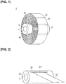
- Figure 1 is a perspective view illustrating a roll electrode according to the first embodiment.
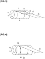
- Figure 2 is a perspective view illustrating a state in which a winding-start end portion of an electrode is fixed to a core using a first tape member.
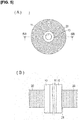
- Figure 3 is a perspective view illustrating a state in which an electrode has been wound around the core once.
- Figure 4 is a perspective view illustrating a state in which an intermediate portion of an electrode is fixed to a core using a second tape member.
- the roll electrode 1 according to the first embodiment comprises a cylindrical core 10 that extends in the axial direction (left/right direction in Figure 1 ), and an electrode 20 that is wound into a roll shape on the outer circumference of the core 10, as illustrated in Figures 1-4 .
- the roll electrode 1 further comprises a first tape member (corresponding to the fixing part) 30 that fixes a winding-start end portion 21 of the electrode 20 to the core 10, and a second tape member (corresponding to the regulating part) 40 that fixes an intermediate portion 23 of the electrode 20 to the core 10.
- the core 10 has a through-hole 11 that extends therethrough in the axial direction, as illustrated in Figure 1 .
- a rotatable winding shaft (not shown) is inserted in the through-hole 11 when winding the electrode 20 around the core 10.
- the core 10 is not limited as long as the outer circumference is substantially circular, and may have a columnar shape or the like.
- the material that constitutes the core 10 is, for example, aluminum. However, the material is not limited thereto, and may be another metal material as long as the metal has a higher thermal expansion coefficient than the thermal expansion coefficient of the electrode 20.
- the electrode 20 comprises a current collector and an active material layer.
- An example of a method for layering an active material layer on the current collector is a method to coat, and dry, an electrode slurry on the current collector, but no limitation is imposed thereby.
- the electrode 20 may be configured such that an active material layer is layered on both sides of the current collector, or such that an active material layer is layered on one side of the current collector.
- the electrode 20 comprises a negative electrode and a positive electrode.
- a member that is conventionally used as a battery current collector may be appropriately employed as the material constituting the negative electrode current collector.
- Examples include aluminum, nickel, iron, stainless steel (SUS), titanium, and copper.
- SUS stainless steel
- copper is preferable as a negative electrode current collector from the point of view of electron conductivity and battery operating potential.
- the thickness of the negative electrode current collector is not particularly limited, and is set giving consideration to the intended use of the battery.
- the negative electrode active material layer is, for example, hard carbon (non-graphitizable carbon material).
- hard carbon non-graphitizable carbon material
- no limitation is imposed thereby, and it is also possible to use a graphite carbon material or a lithium-transition metal composite oxide.
- a negative electrode active material comprising carbon and lithium-transition metal composite oxide is favorable from the point of view of capacity and output characteristics.
- the same material constituting the negative electrode current collector may be used as the material constituting the positive electrode current collector.
- aluminum is preferable as a positive electrode current collector from the point of view of electron conductivity and battery operating potential.
- no limitation is imposed thereby, and it is also possible to use an aluminum foil, a clad material of nickel and aluminum, a clad material of copper and aluminum, or plating material of a combination of these metals.
- the thickness of the positive electrode current collector is not particularly limited, and is set giving consideration to the intended use of the battery.
- An example of a material constituting the positive electrode active material layer is LiMn 2 O 4 .
- LiMn 2 O 4 LiMn 2 O 4 .
- the combination of the current collector and the active material layer of the electrode 20 it is necessary for the combination of the current collector and the active material layer of the electrode 20 to be a combination in which a gap is generated between the core 10 and the electrode 20 after heat treatment, as described later. That is, it is necessary for the combination to have, as the electrode 20 as a whole, a lower thermal expansion coefficient than the thermal expansion coefficient of the core 10.
- the first tape member 30 fixes the winding-start end portion 21 of the electrode 20 to the core 10, as illustrated in Figure 2 .
- the first tape member 30 is attached across the entire region in the axial direction of the winding-start end portion 21 of the electrode 20.
- the winding -start end portion 21 is the position from which the electrode 20 starts being wound around the core 10.
- the first tape member 30 has adhesiveness on the lower surface side in Figure 2 .
- a tape that uses an acrylic adhesive may be used as the first tape member 30, but no limitation is imposed thereby, and any tape member that is capable of fixing the winding-start end portion 21 of the electrode 20 to the core 10 may be used.
- the second tape member 40 fixes an intermediate portion 23 between the winding-start end portion 21 and the winding-finish end portion 22 of the electrode 20 to the core 10, as illustrated in Figures 3, 4 .
- the winding-finish end portion 22 is the position where the electrode 20 is finished being wound around the core 10 (refer to Figure 1 ).
- the second tape member 40 has adhesiveness on the lower surface side in Figure 3 .
- the intermediate portion 23 is located in a winding region of the electrode 20 that is wound around the core 10 during the second turn, as illustrated in Figures 3, 4 . That is, the second tape member 40 is attached to the outer circumference of the winding region of the electrode 20 that is wound around the core 10 during the second turn, and fixes the intermediate portion 23 to the core 10.
- the core 10 presses the electrode 20 radially outward. Consequently, the surface roughness of the winding region of the electrode 20 that is wound around the core 10 during the first turn is particularly reduced. If the second tape member 40 is attached to the winding region of the first turn, where the surface roughness has been reduced, the adhesive force of the second tape member 40 with respect to the winding region of the electrode 20 that is wound around the core 10 during the first turn is reduced, and the effect to suppress winding deviation is decreased.
- the second tape member 40 it is preferable for the second tape member 40 to avoid the winding region of the electrode 20 that is wound around the core 10 during the first turn, and to be attached to the winding region that is wound around during the second turn or later.
- the present invention includes a mode in which the second tape member 40 is attached to the winding region of the electrode 20 that is wound around the core 10 during the first turn.
- the second tape member 40 is attached to the intermediate portion 23 of the electrode 20 across the entire region in the axial direction, as illustrated in Figure 4 .
- the second tape member 40 is disposed in a different position in the circumferential direction with respect to the first tape member 30 when viewed from the axial direction, as illustrated in Figure 4 .
- the second tape member 40 may be disposed in the same position in the circumferential direction, with respect to the first tape member 30.
- the same material that constitutes the first tape member 30 may be used as the material constituting the second tape member 40.
- the winding-start end portion 21 of the electrode 20 is fixed to the core 10 by the first tape member 30, as illustrated in Figure 2 .
- the electrode 20 is wound into a roll shape around the outer circumference of the core 10, up to the intermediate portion 23 between the winding-start end portion 21 and the winding-finish end portion 22.
- the intermediate portion 23 is fixed to the core 10 by the second tape member 40, as illustrated in Figure 4 .
- the electrode 20 is wound into a roll shape around the outer circumference of the core 10 up to the winding-finish end portion 22 (refer to Figure 1 ).
- Figures 5-8 are views for explaining the mechanism by which a winding deviation occurs.
- Figure 5 is a view illustrating a roll electrode 1 before heat treatment
- Figure 5(A) is a side surface view
- Figure 5(B) is a schematic cross-sectional view taken along section line 5B-5B in Figure 5(A)
- Figure 6 is a view illustrating a roll electrode 1 immediately after heat treatment
- Figure 6(A) is a side surface view
- Figure 6(B) is a schematic cross-sectional view taken along section line 6B-6B in Figure 6(A) .
- Figure 7 is a view illustrating a roll electrode 1 when the temperature has returned to the atmospheric temperature after heat treatment;
- Figure 7(A) is a side surface view, and
- Figure 7(B) is a schematic cross-sectional view taken along section line 7B-7B in Figure 7(A) .
- Figure 8 is a schematic view illustrating the state of a winding deviation.
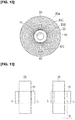
- Figure 9 is a view for explaining the effect of the roll electrode 1 according to the present embodiment.
- the first tape member 30 is omitted for ease of understanding.
- the hatching is omitted in Figures 5(B) , 6(B) , and 7(B) .
- a side surface view is as viewed from the axial direction.
- Heat treatment is carried out for the purpose of removing moisture, and the like, present inside the roll electrode, with respect to a roll electrode in which an electrode 20 is wound around a core 10, as illustrated in Figures 5(A), (B) .
- Heat treatment entails, for example, vacuum drying carried out for 24 hours at 150°C.
- the core 10 and the electrode 20 are thermally expanded, as illustrated in Figure 6(A) . More specifically, the core 10 expands so as to spread radially inward and radially outward. In addition, the electrode 20 expands so as to spread radially outward. Since the core 10 and the electrode 20 are thermally expanded in this manner, the electrode 20 receives a compressive force from the core 10 in the vicinity of the winding-start end portion 21 of the electrode 20 (refer to the arrow in Figure 6(B) ). As a result, the current collector of the electrode 20 is plastically deformed in the vicinity of the winding-start end portion 21, and the minute gap between the electrodes 20 that is generated when winding the electrode 20 around the core 10 is filled. Therefore, the thickness W of the electrode 20 decreases toward the inner circumferential side where the winding-start end portion 21 is located, as illustrated in Figure 6(B) .
- the core 10 returns to the shape before the heat treatment, as illustrated in Figures 7(A), (B) .
- the current collector of the electrode 20 is plastically deformed at the time of the heat treatment, as described above, and the minute gap between the electrodes 20 that is generated when winding the electrode 20 around the core 10 is filled; therefore, the shape of the electrode does not return to the shape before the heat treatment, and becomes the shape illustrated in Figures 7(A), (B) .
- a gap S1 is formed between the core 10 and the electrode 20, and a gap S2 is also formed between the electrodes 20 in the vicinity of the winding-start end portion 21.
- the gap S2 is formed smaller than the gap S1, and is formed to become smaller from the inner circumferential side to the outer circumferential side of the core 10.
- the fixing force of the electrode 20 to the core 10 is enhanced. Accordingly, it is possible to suppress an occurrence of winding deviation.
- the second tape member 40 since a winding deviation tends to occur on the inner circumferential side of the electrode 20, it is preferable for the second tape member 40 to be attached on the inner circumferential side of the electrode 20, which is wound into a roll shape.
- the roll electrode 1 comprises a cylindrical core 10 that extends in the axial direction and an electrode 20 that has an thermal expansion coefficient that is lower than the thermal expansion coefficient of the core 10 and that is wound into a roll shape on the outer circumference of the core 10.
- the roll electrode 1 further comprises a first tape member 30 for fixing the winding-start end portion 21 of the electrode 20 to the core 10 and a second tape member 40 for regulating the axial movement of the electrode 20 wound into a roll shape with respect to the core 10. Accordingly, it is possible to suppress the generation of winding deviation in a roll electrode 1 in which the thermal expansion coefficient of the core 10 is higher than the thermal expansion coefficient of the electrode 20 by the second tape member 40.
- the second tape member 40 is a tape member that fixes the intermediate portion 23 between the winding-start end portion 21 and the winding-finish end portion 22 of the electrode 20 to the core 10. Accordingly, the fixing force of the electrode 20 to the core 10 is enhanced by the second tape member 40. Therefore, it is possible to suppress an occurrence of winding deviation using an easy method to attach the second tape member 40 to the core 10 and the intermediate portion 23.
- the second tape member 40 fixes the intermediate portion 23 located in the winding region of the electrode 20 that is wound around the core 10 during the second turn to the core 10. Accordingly, the inner circumferential side of the electrode 20, where winding deviation particularly occurs, is fixed to the core 10 using the second tape member 40. Therefore, it is possible to favorably suppress an occurrence of winding deviation. Furthermore, since the second tape member 40 is attached while avoiding the winding region of the electrode during the first turn, where the surface roughness is reduced by the heat treatment, as described above, it is possible to more favorably suppress an occurrence of winding deviation.
- first tape member 30 and the second tape member 40 are disposed in different positions from each other in the circumferential direction when viewed from the axial direction. Accordingly, compared to when the first tape member 30 and the second tape member 40 are disposed in the same position in the circumferential direction, the height of the step that is generated radially outward, due to the thicknesses of the first tape member 30 and the second tape member 40, can be reduced. Therefore, it is possible to suppress the occurrence of loosening in the winding or tightening of the winding, when winding the electrode 20 around the core 10.
- the winding-start end portion 21 of the electrode 20, having a lower thermal expansion coefficient than the thermal expansion coefficient of the core 10, is fixed to the cylindrical core 10 that extends in the axial direction.
- the electrode 20 is wound into a roll shape around the outer circumference of the core 10, up to the intermediate portion 23 between the winding-start end portion 21 and the winding-finish end portion 22.
- the intermediate portion 23 is fixed to the core 10 using the second tape member 40, and the electrode 20 is wound into a roll shape around the outer circumference of the core 10 up to the winding-finish end portion 22.
- the intermediate portion 23 between the winding-start end portion 21 and the winding-finish end portion 22 is fixed to the core 10 using the second tape member 40. Accordingly, the fixing force of the electrode 20 to the core 10 is enhanced. Therefore, it is possible to suppress the generation of winding deviation in the roll electrode 1 in which the thermal expansion coefficient of the core 10 is higher than the thermal expansion coefficient of the electrode 20.
- FIG 10 is a perspective view illustrating a roll electrode 2 according to the modified example 1.
- the second tape member 40 is attached to the intermediate portion 23 of the electrode 20 across the entire region in the axial direction.
- the second tape member 240 may be provided shorter than the width W1 of the electrode 20 along the axial direction, and at least an edge 24 of the electrode 20 along a direction intersecting the axial direction may be fixed to the core 10, as illustrated in Figure 10 . According to this configuration, it is possible to reduce the amount of the second tape member 240 that is used compared to the first embodiment; therefore, the roll electrode 2 can be manufactured at a low cost.
- the electrode 20 in the winding region of the third turn comes in contact with an exposed portion 26 where the electrode 20 is exposed, located between the second tape members 240. Accordingly, if the surface roughness of the electrode 20 is greater than that of the second tape member 240, the frictional force between the winding region of the second turn and the winding region of the third turn of the electrode 20 is increased, compared to a configuration in which the second tape member 40 is attached to the intermediate portion 23 across the entire region in the axial direction. Therefore, it is possible to more favorably suppress an occurrence of winding deviation.
- Figure 11 is a perspective view illustrating a roll electrode 3 according to the modified example 2.
- the second tape member 40 fixes the intermediate portion 23 located in the winding region of the electrode 20 that is wound around the core 10 during the second turn to the core 10.
- the intermediate portion 323, which is fixed to the core 10 may be positioned on the inner circumferential side of the central portion 20C of the outermost perimeter 20A and the innermost perimeter 20B of the electrode 20, which is arranged in a roll shape, as viewed from the axial direction, as illustrated in Figure 11 .
- An intermediate portion 423 that is fixed to the core 10 may be positioned on the outer circumferential side of the central portion 20C, as illustrated in Figure 12 .
- first tape member 30 and the second tape member 40 a single-sided tape having adhesiveness on one side was used for the first tape member 30 and the second tape member 40.
- first tape member 30 and the second tape member 40 may be a double-sided tape having adhesiveness on both sides.
- the core 10 is configured from a metal material having a higher thermal expansion coefficient than the core 20, such as aluminum.
- the core may be a paper tube.
- a paper tube expands and contracts due to absorption of moisture. Therefore, since winding deviation occurs with transportation even if the core is a paper tube, it is possible to suppress an occurrence of winding deviation by fixing the intermediate portion 23 of the electrode 20 to the core using the second tape member 40. Therefore, in the present invention, the concept of the expansion coefficient includes the concepts of both a thermal expansion coefficient due to heat treatment and an expansion coefficient due to absorption of moisture.
- a negative electrode slurry was prepared by dispersing massive artificial graphite (MAGD manufactured by Hitachi Chemical Co., Ltd.): PVdF (polyvinylidene fluoride, binder) in NMP (N-methylpyrrolidone) at a composition ratio of 92:8. Thereafter, the negative electrode slurry was coated onto the surface of a Cu foil having a thickness of 10 ⁇ m using a die coater, and a negative electrode was prepared by float drying at 80°C. Thereafter, pressing was carried out to pack the negative electrode to a density of 1.4 g/cc. The thickness of the electrode 20 was 130 ⁇ m.
- massive artificial graphite MALD manufactured by Hitachi Chemical Co., Ltd.
- NMP N-methylpyrrolidone
- the electrode 20 was wound around the core 10 to produce a roll electrode 1.
- the winding length per one electrode was set to 900 m.
- the outer diameter of the core was 160 mm.
- the second tape member 40 was fixed in a position separated from the first tape member 30 by 10 m.
- the second tape member 240 was fixed in a position separated from the first fixing portion by 10 m.
- a paper tube was used as the material of the core.
- the fixing method illustrated in Figure 1 and described in the first embodiment was used as the fixing method.
- Aluminum was used as the material of the core.
- first tape member 30 was used and a second tape member 40 was not used as the fixing method.
- a paper tube was used as the material of the core.
- only the first tape member 30 was used and a second tape member 40 was not used as the fixing method.
- thermohygrostat bath test will be described. Specifically, roll electrodes were placed in a thermohygrostat bath to carry out a heat cycle test. The conditions were as follows.
- a load test was carried out on the roll electrode subjected to the thermohygrostat bath test or the heat treatment test. Specifically, roll electrodes were placed in a transport case, and a stop/go test was carried out using a forklift. The conditions were as follows.
- a score line L was drawn, and the winding deviation amount D after the above-described load test was measured, as illustrated in Figure 13 .
- Example 1 according to the first embodiment and Example 2 according to Modified Example 1, it can be seen that generation of winding deviation can be more favorably suppressed using Example 2 according to Modified Example 1. This is because, as described above, if the surface roughness of the electrode 20 is greater than that of the second tape member 240, the frictional force between the winding region of the second turn and the winding region of the third turn of the electrode 20 is increased, by an exposed portion 26 where the electrode 20 is exposed being provided between the second tape members 240.
- the roll electrode 4 according to the second embodiment is different from the roll electrode 1 according to the first embodiment in the means for suppressing generation of winding deviation.
- Figure 14 is a perspective view illustrating a roll electrode 4 according to the second embodiment.
- Figure 15 is a cross-sectional view taken along the 15-15 line of Figure 14 .
- the roll electrode 4 according to the second embodiment comprises a core 110, an electrode 20, a first tape member 30, and a ring plate (corresponding to the regulating part) 140, as illustrated in Figure 14 .
- the configurations of the electrode 20 and the first tape member 30 are the same as the configuration of the roll electrode 1 according to the first embodiment, and thus descriptions thereof are omitted.
- the core 110 comprises a through-hole 11 extending in the axial direction and two groove portions 113A, 113B provided to the outer perimeter portion 112, as illustrated in Figure 15 .
- the two groove portions 113A, 113B are provided on both sides of the electrode 20 in the axial direction, as illustrated in Figure 15 .
- Protrusions 144 of the ring plate 140, described later, are fitted to the two groove portions 113A, 113B.
- the ring plate 140 regulates the axial movement of the electrode 20 wound into a roll shape with respect to the core 10.
- Two ring plates 140 are disposed on both sides of the electrode 20 wound into a roll shape in the axial direction.
- the ring plate 140 comprises a main body portion 141, a recess 142 provided on the inner circumferential side of the main body portion 141, an elastic member 143 disposed in the recess 142, and a protrusion 144 to which a radially inward biasing force is applied by the elastic member 143, as illustrated in Figure 15 .
- the outer circumference of the main body portion 141 is configured to be on the inner circumferential side of the central portion 20C between the outermost perimeter 20A and the innermost perimeter 20B of the electrode 20, which is arranged in a roll shape, as viewed from the axial direction.
- the outer circumference of the main body portion 141 may be configured to exceed the central portion 20C to be on the outer circumferential side.
- the elastic member 143 is fixed to the recess 142.
- the protrusion 144 is fixed to the elastic member 143.
- the respective fixing means are not particularly limited.
- the protrusion 144 is imparted with a radially inward biasing force by the elastic member 143 and is fitted to the two groove portions 113A, 113B of the core 110.
- the ring plate 140 is thereby fixed to the outer circumference of the core 110.
- ring plates 140 are disposed on both sides in the axial direction of the electrode 20 that is wound into a roll shape. Accordingly, it is possible to suppress the generation of winding deviation in the roll electrode 4 in which the expansion coefficient of the core 110 is higher than the expansion coefficient of the electrode 20 by the ring plates 140.
- the winding-start end portion 21 of the electrode 20 is fixed to the core 110 using the first tape member 30.
- the electrode 20 is wound into a roll shape around the outer circumference of the core 110 up to the winding-finish end portion 22 of the electrode 20.
- ring plates 140 are disposed and fixed on both sides in the axial direction of the electrode 20 that is wound into a roll shape, on the outer circumference of the core 110.
- the protrusion 144 of the ring plate 140 is imparted with a radially inward biasing force by the elastic member 143 and is fitted to the two groove portions 113A, 113B of the core 110.
- the manufacturing method is not limited to the manufacturing method described above and may be a manufacturing method in which the electrode 20 is wound into a roll shape around the outer circumference of the core 110, after the ring plates 140 are disposed and fixed on the outer circumference of the core 110.
- the ring plates 140 of the roll electrode 4 according to the second embodiment are fixably disposed on the outer circumference of the core 110, on both sides in the axial direction of the electrode 20, which is wound into a roll shape. Accordingly, it is possible to suppress the generation of winding deviation in the roll electrode 4 in which the thermal expansion coefficient of the core 110 is higher than the thermal expansion coefficient of the electrode 20 by the ring plates 140.
- the outer circumference of the ring plate 140 is configured to be on the inner circumferential side of the central portion 20C between the outermost perimeter 20A and the innermost perimeter 20B of the electrode 20, which is arranged in a roll shape, as viewed from the axial direction. Accordingly, it is possible to regulate the movement on the inner circumferential side, where winding deviation particularly occurs.
- the winding-start end portion 21 of the electrode 20, having a lower thermal expansion coefficient than the thermal expansion coefficient of the core 110 is fixed to the cylindrical core 110 that extends in the axial direction. Then, the electrode 20 is wound into a roll shape around the outer circumference of the core 110 up to the winding-finish end portion 22 of the electrode 20, and plates 140 are disposed and fixed on both sides in the axial direction of the electrode 20 that is wound into a roll shape, on the outer circumference of the core 110. Accordingly, it is possible to suppress the generation of winding deviation in the roll electrode 4 in which the thermal expansion coefficient of the core 110 is higher than the thermal expansion coefficient of the electrode 20 by the ring plates 140.
- a pair of ring plates 140 are disposed and fixed on the outer circumference of the cylindrical core 110 that extends in the axial direction, at a predetermined distance from each other in the axial direction. Then, the winding-start end portion 21 of the electrode 20, which has a lower thermal expansion coefficient than the thermal expansion coefficient of the core 110, is fixed to the core 110 between the pair of ring plates 140, and the electrode 20 is wound into a roll shape around the outer circumference of the core 110 up to the winding-finish end portion 22 of the electrode 20. Accordingly, it is possible to suppress the generation of winding deviation in the roll electrode 4 in which the thermal expansion coefficient of the core 110 is higher than the thermal expansion coefficient of the electrode 20 by the ring plates 140.
Landscapes
- Chemical & Material Sciences (AREA)
- Engineering & Computer Science (AREA)
- Chemical Kinetics & Catalysis (AREA)
- Electrochemistry (AREA)
- General Chemical & Material Sciences (AREA)
- Manufacturing & Machinery (AREA)
- Materials Engineering (AREA)
- Secondary Cells (AREA)
- Storage Of Web-Like Or Filamentary Materials (AREA)
- Battery Electrode And Active Subsutance (AREA)
Abstract
Description
- The present invention relates to a roll electrode and a method for manufacturing a roll electrode.
- In recent years, in the automobile industry, advanced electronics industry, and the like, the demand for automobile batteries and batteries for electronic devices is increasing, and there are demands particularly for a reduction in size and thickness, higher capacities, and the like. Of the above, nonaqueous electrolyte secondary batteries, which have higher energy densities compared to other batteries, are attracting attention.
- The manufacturing steps of such nonaqueous electrolyte secondary batteries include a step to form a roll electrode by winding an electrode around the outer circumference of a core that has a substantially circular outer circumference into a roll shape. A roll electrode is subjected to heat treatment to remove moisture and the like contained therein, and then cut into the required length (for example, Patent Document 1).
-
Patent Document 2 discloses a method of fixing an original printing plate at the start of winding to a hollow core using tape, in the field of roll-shaped original printing plates with a long original printing plate wound around a hollow core. It also discloses that the thickness of this tape is equal to or less than 0-20% of the thickness of the original printing plate. According to this roll-shaped original printing plate, it is possible to carry out winding without the stepped shape at the start of winding, which occurs near the hollow core, being transferred, and winding up can be carried out in a good state without generating loosening in the winding or tightening of the winding, to thereby improve the quality. -
- Patent Document 1: Japanese Laid Open Patent Application No.
2014-107237 - Patent Document 2: Japanese Laid Open Patent Application No.
2006-44838 - Here, there are cases in which a roll electrode, such as that disclosed in
Patent Document 1, is transported to the place where cutting is carried out after being subjected to heat treatment. The present inventors found a problem in that a phenomenon occurs in which, when transporting the roll electrode after carrying out the heat treatment described above, the electrode that is wound into a roll shape is shifted in the axial direction with respect to the core (so-called winding deviation). Furthermore, according to evaluations made by the present inventors, this problem occurs particularly when the expansion coefficient of the core that configures the roll electrode is higher than the expansion coefficient of the electrode. The cause of the problem was found to be that, when the heat treatment is applied, the electrode receives a compressive force from the core and a gap is generated after the heat treatment between the core and the electrode as well as between electrodes. Furthermore, it was found that generation of a winding deviation cannot be prevented, even if the end portion from which the electrode starts being wound around the core is fixed, as in the technique disclosed inPatent Document 2 described above. - The present invention was done to solve the problem described above, and an object thereof is to provide a means capable of suppressing the generation of winding deviation in a roll electrode in which the expansion coefficient of a core is higher than that of an electrode.
- The roll electrode according to the present invention that achieves the object described above comprises a core that extends in the axial direction and has a substantially circular outer circumference, and an electrode that has an expansion coefficient that is lower than the expansion coefficient of the core and that is wound into a roll shape on the outer circumference of the core. Additionally, the roll electrode comprises a fixing part for fixing an end portion from which the electrode starts being wound around the core, and a regulating part for regulating the axial movement of the electrode wound into a roll shape with respect to the core.
- In addition, in the method for manufacturing a roll electrode according to the present invention that achieves the object described above, a winding-start end portion of an electrode that has an expansion coefficient that is lower than the expansion coefficient of a core is fixed to the core, which extends in the axial direction and has a substantially circular outer circumference. Then, the electrode is wound into a roll shape around the outer circumference of the core up to an intermediate portion between the winding-start end portion and the winding-finish end portion of the electrode. Then, the intermediate portion is fixed to the core using tape, and the electrode is wound into a roll shape around the outer circumference of the core up to the winding-finish end portion.
- In addition, in the method for manufacturing a roll electrode according to the present invention that achieves the object described above, a winding-start end portion of an electrode that has an expansion coefficient that is lower than the expansion coefficient of a core is fixed to the core, which extends in the axial direction and has a substantially circular outer circumference. Then, the electrode is wound into a roll shape around the outer circumference of the core up to the winding-finish end portion of the electrode. Then, ring plates are disposed and fixed on both sides in the axial direction of the electrode that is wound into a roll shape, on the outer circumference of the core.
- In addition, in the method for manufacturing a roll electrode according to the present invention that achieves the object described above, a pair of ring plates are disposed and fixed on the outer circumference of a core that extends in the axial direction and has a substantially circular outer circumference, at a predetermined distance from each other in the axial direction. Then, a winding-start end portion of an electrode that has an expansion coefficient that is lower than the expansion coefficient of a core is fixed to the core between the pair of ring plates. Then, the electrode is wound into a roll shape around the outer circumference of the core up to the winding-finish end portion of the electrode.
- The roll electrode configured as described above comprises a regulating part for regulating the axial movement of the electrode wound into a roll shape with respect to the core. Accordingly, it is possible to prevent a winding deviation, which occurs due to a gap being generated between the core and the electrode as well as between electrodes after the heat treatment, in a roll electrode in which the expansion coefficient of the core is higher than the expansion coefficient of the electrode.
- Additionally, according to the method for manufacturing a roll electrode configured as described above, an intermediate portion between the winding-start end portion and the winding-finish end portion of an electrode is fixed to the core using tape. Accordingly, the fixing force of the electrode to the core is enhanced. Therefore, it is possible to suppress the generation of winding deviation in a roll electrode in which the expansion coefficient of a core is higher than the expansion coefficient of an electrode.
- Furthermore, according to the method for manufacturing a roll electrode configured as described above, ring plates are disposed on both sides in the axial direction of the electrode that is wound into a roll shape. Accordingly, it is possible to suppress the generation of winding deviation in a roll electrode in which the expansion coefficient of a core is higher than the expansion coefficient of an electrode using the ring plates.
-
- [
Figure 1 ] is a perspective view illustrating a roll electrode according to the first embodiment. - [
Figure 2 ] is a perspective view illustrating a state in which a winding-start end portion of an electrode is fixed to a core using a first tape member. - [
Figure 3 ] is a perspective view illustrating a state in which an electrode has been wound around the core once. - [
Figure 4 ] is a perspective view illustrating a state in which an intermediate portion of an electrode is fixed to a core using a second tape member. - [
Figure 5 ] is a view illustrating a roll electrode before heat treatment;Figure 5(A) is a side surface view, andFigure 5(B) is a schematic cross-sectional view cross-sectional view as seen alongsection line 5B-5B inFigure 5(A) . - [
Figure 6 ] is a view illustrating a roll electrode immediately after heat treatment;Figure 6(A) is a side surface view, andFigure 6(B) is a schematic cross-sectional view cross-sectional view as seen alongsection line 6B-6B inFigure 6(A) . - [
Figure 7 ] is a view illustrating a roll electrode when the temperature has returned to the atmospheric temperature after heat treatment;Figure 7(A) is a side surface view, andFigure 7(B) is a schematic cross-sectional view taken along the 7B-7B line inFigure 7(A) . - [
Figure 8 ] is a schematic view illustrating the state of a winding deviation. - [
Figure 9 ] is a view for explaining the effect of the roll electrode according to the present embodiment. - [
Figure 10 ] is a perspective view illustrating a roll electrode according to the modified example 1. - [
Figure 11 ] is a perspective view illustrating a roll electrode according to the modified example 2. - [
Figure 12 ] is a schematic view illustrating a configuration in which the intermediate portion is located on the outer circumference side of the central portion. - [
Figure 13 ] is a view for explaining the method of measuring the winding deviation amount. - [
Figure 14 ] is a perspective view illustrating a roll electrode according to the second embodiment. - [
Figure 15 ] is a cross-sectional view as seen along section line 15-15 ofFigure 14 . - The first embodiment according to the present invention will be described below, with reference to the appended drawings. In the explanations of the drawings, the same elements are given the same reference symbols, and overlapping explanations are omitted. The dimensional ratios in the drawings are exaggerated for convenience of explanation, and are different from the actual ratios.
-
Figure 1 is a perspective view illustrating a roll electrode according to the first embodiment.Figure 2 is a perspective view illustrating a state in which a winding-start end portion of an electrode is fixed to a core using a first tape member.Figure 3 is a perspective view illustrating a state in which an electrode has been wound around the core once.Figure 4 is a perspective view illustrating a state in which an intermediate portion of an electrode is fixed to a core using a second tape member. - The
roll electrode 1 according to the first embodiment comprises acylindrical core 10 that extends in the axial direction (left/right direction inFigure 1 ), and anelectrode 20 that is wound into a roll shape on the outer circumference of thecore 10, as illustrated inFigures 1-4 . Theroll electrode 1 further comprises a first tape member (corresponding to the fixing part) 30 that fixes a winding-start end portion 21 of theelectrode 20 to thecore 10, and a second tape member (corresponding to the regulating part) 40 that fixes anintermediate portion 23 of theelectrode 20 to thecore 10. - The
core 10 has a through-hole 11 that extends therethrough in the axial direction, as illustrated inFigure 1 . A rotatable winding shaft (not shown) is inserted in the through-hole 11 when winding theelectrode 20 around thecore 10. Thecore 10 is not limited as long as the outer circumference is substantially circular, and may have a columnar shape or the like. - The material that constitutes the
core 10 is, for example, aluminum. However, the material is not limited thereto, and may be another metal material as long as the metal has a higher thermal expansion coefficient than the thermal expansion coefficient of theelectrode 20. - The
electrode 20 comprises a current collector and an active material layer. An example of a method for layering an active material layer on the current collector is a method to coat, and dry, an electrode slurry on the current collector, but no limitation is imposed thereby. Theelectrode 20 may be configured such that an active material layer is layered on both sides of the current collector, or such that an active material layer is layered on one side of the current collector. - The
electrode 20 comprises a negative electrode and a positive electrode. - A member that is conventionally used as a battery current collector may be appropriately employed as the material constituting the negative electrode current collector. Examples include aluminum, nickel, iron, stainless steel (SUS), titanium, and copper. Of the above, copper is preferable as a negative electrode current collector from the point of view of electron conductivity and battery operating potential. The thickness of the negative electrode current collector is not particularly limited, and is set giving consideration to the intended use of the battery.
- The negative electrode active material layer is, for example, hard carbon (non-graphitizable carbon material). However, no limitation is imposed thereby, and it is also possible to use a graphite carbon material or a lithium-transition metal composite oxide. In particular, a negative electrode active material comprising carbon and lithium-transition metal composite oxide is favorable from the point of view of capacity and output characteristics.
- The same material constituting the negative electrode current collector may be used as the material constituting the positive electrode current collector. Of the above, aluminum is preferable as a positive electrode current collector from the point of view of electron conductivity and battery operating potential. However, no limitation is imposed thereby, and it is also possible to use an aluminum foil, a clad material of nickel and aluminum, a clad material of copper and aluminum, or plating material of a combination of these metals. The thickness of the positive electrode current collector is not particularly limited, and is set giving consideration to the intended use of the battery.
- An example of a material constituting the positive electrode active material layer is LiMn2O4. However, no particular limitation is imposed thereby. It is preferable to apply lithium-transition metal composite oxide, from the point of view of capacity and output characteristics.
- In the present invention, it is necessary for the combination of the current collector and the active material layer of the
electrode 20 to be a combination in which a gap is generated between the core 10 and theelectrode 20 after heat treatment, as described later. That is, it is necessary for the combination to have, as theelectrode 20 as a whole, a lower thermal expansion coefficient than the thermal expansion coefficient of thecore 10. - The
first tape member 30 fixes the winding-start end portion 21 of theelectrode 20 to thecore 10, as illustrated inFigure 2 . Thefirst tape member 30 is attached across the entire region in the axial direction of the winding-start end portion 21 of theelectrode 20. The winding -start end portion 21 is the position from which theelectrode 20 starts being wound around thecore 10. - The
first tape member 30 has adhesiveness on the lower surface side inFigure 2 . - For example, a tape that uses an acrylic adhesive may be used as the
first tape member 30, but no limitation is imposed thereby, and any tape member that is capable of fixing the winding-start end portion 21 of theelectrode 20 to the core 10 may be used. - The
second tape member 40 fixes anintermediate portion 23 between the winding-start end portion 21 and the winding-finish end portion 22 of theelectrode 20 to thecore 10, as illustrated inFigures 3, 4 . The winding-finish end portion 22 is the position where theelectrode 20 is finished being wound around the core 10 (refer toFigure 1 ). - The
second tape member 40 has adhesiveness on the lower surface side inFigure 3 . - In the present embodiment, the
intermediate portion 23 is located in a winding region of theelectrode 20 that is wound around thecore 10 during the second turn, as illustrated inFigures 3, 4 . That is, thesecond tape member 40 is attached to the outer circumference of the winding region of theelectrode 20 that is wound around thecore 10 during the second turn, and fixes theintermediate portion 23 to thecore 10. - Meanwhile, due to thermal expansion of the
core 10 and theelectrode 20 using a heat treatment for removing moisture, and the like, the core 10 presses theelectrode 20 radially outward. Consequently, the surface roughness of the winding region of theelectrode 20 that is wound around thecore 10 during the first turn is particularly reduced. If thesecond tape member 40 is attached to the winding region of the first turn, where the surface roughness has been reduced, the adhesive force of thesecond tape member 40 with respect to the winding region of theelectrode 20 that is wound around thecore 10 during the first turn is reduced, and the effect to suppress winding deviation is decreased. Therefore, it is preferable for thesecond tape member 40 to avoid the winding region of theelectrode 20 that is wound around thecore 10 during the first turn, and to be attached to the winding region that is wound around during the second turn or later. However, the present invention includes a mode in which thesecond tape member 40 is attached to the winding region of theelectrode 20 that is wound around thecore 10 during the first turn. - The
second tape member 40 is attached to theintermediate portion 23 of theelectrode 20 across the entire region in the axial direction, as illustrated inFigure 4 . - The
second tape member 40 is disposed in a different position in the circumferential direction with respect to thefirst tape member 30 when viewed from the axial direction, as illustrated inFigure 4 . By disposing thesecond tape member 40 in this manner, compared to when being disposed in the same position in the circumferential direction, the height of the step that is generated radially outward, caused by the thicknesses of thefirst tape member 30 and thesecond tape member 40, can be reduced. Therefore, it is possible to suppress the occurrence of loosening in the winding or tightening of the winding, when winding theelectrode 20 around thecore 10. Thesecond tape member 40 may be disposed in the same position in the circumferential direction, with respect to thefirst tape member 30. - The same material that constitutes the
first tape member 30 may be used as the material constituting thesecond tape member 40. - Next, the method for manufacturing a
roll electrode 1 according to the first embodiment will be described. - First, the winding-
start end portion 21 of theelectrode 20 is fixed to the core 10 by thefirst tape member 30, as illustrated inFigure 2 . - Next, the
electrode 20 is wound into a roll shape around the outer circumference of the core 10, up to theintermediate portion 23 between the winding-start end portion 21 and the winding-finish end portion 22. - Next, the
intermediate portion 23 is fixed to the core 10 by thesecond tape member 40, as illustrated inFigure 4 . - Then, the
electrode 20 is wound into a roll shape around the outer circumference of the core 10 up to the winding-finish end portion 22 (refer toFigure 1 ). - Next, the effect of the
roll electrode 1 according to the first embodiment will be described, with reference toFigures 5-9. Figures 5-8 are views for explaining the mechanism by which a winding deviation occurs. Specifically,Figure 5 is a view illustrating aroll electrode 1 before heat treatment;Figure 5(A) is a side surface view, andFigure 5(B) is a schematic cross-sectional view taken alongsection line 5B-5B inFigure 5(A) .Figure 6 is a view illustrating aroll electrode 1 immediately after heat treatment;Figure 6(A) is a side surface view, andFigure 6(B) is a schematic cross-sectional view taken alongsection line 6B-6B inFigure 6(A) .Figure 7 is a view illustrating aroll electrode 1 when the temperature has returned to the atmospheric temperature after heat treatment;Figure 7(A) is a side surface view, andFigure 7(B) is a schematic cross-sectional view taken alongsection line 7B-7B inFigure 7(A) .Figure 8 is a schematic view illustrating the state of a winding deviation.Figure 9 is a view for explaining the effect of theroll electrode 1 according to the present embodiment. InFigures 5-9 , thefirst tape member 30 is omitted for ease of understanding. In addition, the hatching is omitted inFigures 5(B) ,6(B) , and7(B) . Furthermore, a side surface view is as viewed from the axial direction. - First, the mechanism by which a winding deviation occurs will be described, with reference to
Figures 5-8 . - Heat treatment is carried out for the purpose of removing moisture, and the like, present inside the roll electrode, with respect to a roll electrode in which an
electrode 20 is wound around acore 10, as illustrated inFigures 5(A), (B) . Heat treatment entails, for example, vacuum drying carried out for 24 hours at 150°C. - As a result, the
core 10 and theelectrode 20 are thermally expanded, as illustrated inFigure 6(A) . More specifically, thecore 10 expands so as to spread radially inward and radially outward. In addition, theelectrode 20 expands so as to spread radially outward. Since thecore 10 and theelectrode 20 are thermally expanded in this manner, theelectrode 20 receives a compressive force from the core 10 in the vicinity of the winding-start end portion 21 of the electrode 20 (refer to the arrow inFigure 6(B) ). As a result, the current collector of theelectrode 20 is plastically deformed in the vicinity of the winding-start end portion 21, and the minute gap between theelectrodes 20 that is generated when winding theelectrode 20 around thecore 10 is filled. Therefore, the thickness W of theelectrode 20 decreases toward the inner circumferential side where the winding-start end portion 21 is located, as illustrated inFigure 6(B) . - Then, when the temperature returns to atmospheric temperature after the heat treatment, the core 10 returns to the shape before the heat treatment, as illustrated in
Figures 7(A), (B) . In contrast, the current collector of theelectrode 20 is plastically deformed at the time of the heat treatment, as described above, and the minute gap between theelectrodes 20 that is generated when winding theelectrode 20 around thecore 10 is filled; therefore, the shape of the electrode does not return to the shape before the heat treatment, and becomes the shape illustrated inFigures 7(A), (B) . Specifically, a gap S1 is formed between the core 10 and theelectrode 20, and a gap S2 is also formed between theelectrodes 20 in the vicinity of the winding-start end portion 21. The gap S2 is formed smaller than the gap S1, and is formed to become smaller from the inner circumferential side to the outer circumferential side of thecore 10. - When a roll electrode, in which gaps S1 and S2 are formed in this manner, is transported, in the event a
second tape member 40 is not provided as a comparative example, a winding deviation occurs, in which theelectrode 20 moves in the axial direction with respect to thecore 10, as illustrated inFigure 8 (refer to the arrow inFigure 8 ). The winding deviation occurs particularly on the inner circumferential side of theelectrode 20 where the winding-start end portion 21 is located, as illustrated inFigure 8 . - In contrast, by fixing the
intermediate portion 23 to the core 10 using thesecond tape member 40 as illustrated inFigure 9 , the fixing force of theelectrode 20 to thecore 10 is enhanced. Accordingly, it is possible to suppress an occurrence of winding deviation. As described above, since a winding deviation tends to occur on the inner circumferential side of theelectrode 20, it is preferable for thesecond tape member 40 to be attached on the inner circumferential side of theelectrode 20, which is wound into a roll shape. - As described above, the
roll electrode 1 according to the first embodiment comprises acylindrical core 10 that extends in the axial direction and anelectrode 20 that has an thermal expansion coefficient that is lower than the thermal expansion coefficient of thecore 10 and that is wound into a roll shape on the outer circumference of thecore 10. Theroll electrode 1 further comprises afirst tape member 30 for fixing the winding-start end portion 21 of theelectrode 20 to thecore 10 and asecond tape member 40 for regulating the axial movement of theelectrode 20 wound into a roll shape with respect to thecore 10. Accordingly, it is possible to suppress the generation of winding deviation in aroll electrode 1 in which the thermal expansion coefficient of thecore 10 is higher than the thermal expansion coefficient of theelectrode 20 by thesecond tape member 40. - In addition, the
second tape member 40 is a tape member that fixes theintermediate portion 23 between the winding-start end portion 21 and the winding-finish end portion 22 of theelectrode 20 to thecore 10. Accordingly, the fixing force of theelectrode 20 to thecore 10 is enhanced by thesecond tape member 40. Therefore, it is possible to suppress an occurrence of winding deviation using an easy method to attach thesecond tape member 40 to thecore 10 and theintermediate portion 23. - Therefore, the
second tape member 40 fixes theintermediate portion 23 located in the winding region of theelectrode 20 that is wound around thecore 10 during the second turn to thecore 10. Accordingly, the inner circumferential side of theelectrode 20, where winding deviation particularly occurs, is fixed to the core 10 using thesecond tape member 40. Therefore, it is possible to favorably suppress an occurrence of winding deviation. Furthermore, since thesecond tape member 40 is attached while avoiding the winding region of the electrode during the first turn, where the surface roughness is reduced by the heat treatment, as described above, it is possible to more favorably suppress an occurrence of winding deviation. - In addition, the
first tape member 30 and thesecond tape member 40 are disposed in different positions from each other in the circumferential direction when viewed from the axial direction. Accordingly, compared to when thefirst tape member 30 and thesecond tape member 40 are disposed in the same position in the circumferential direction, the height of the step that is generated radially outward, due to the thicknesses of thefirst tape member 30 and thesecond tape member 40, can be reduced. Therefore, it is possible to suppress the occurrence of loosening in the winding or tightening of the winding, when winding theelectrode 20 around thecore 10. - In addition, as described above, in the method for manufacturing a
roll electrode 1 according to the first embodiment, the winding-start end portion 21 of theelectrode 20, having a lower thermal expansion coefficient than the thermal expansion coefficient of the core 10, is fixed to thecylindrical core 10 that extends in the axial direction. Then, theelectrode 20 is wound into a roll shape around the outer circumference of the core 10, up to theintermediate portion 23 between the winding-start end portion 21 and the winding-finish end portion 22. Then, theintermediate portion 23 is fixed to the core 10 using thesecond tape member 40, and theelectrode 20 is wound into a roll shape around the outer circumference of the core 10 up to the winding-finish end portion 22. According to this manufacturing method, theintermediate portion 23 between the winding-start end portion 21 and the winding-finish end portion 22 is fixed to the core 10 using thesecond tape member 40. Accordingly, the fixing force of theelectrode 20 to thecore 10 is enhanced. Therefore, it is possible to suppress the generation of winding deviation in theroll electrode 1 in which the thermal expansion coefficient of thecore 10 is higher than the thermal expansion coefficient of theelectrode 20. - Next, modified examples of the
roll electrode 1 according to the first embodiment will be described. -
Figure 10 is a perspective view illustrating aroll electrode 2 according to the modified example 1. In the first embodiment described above, thesecond tape member 40 is attached to theintermediate portion 23 of theelectrode 20 across the entire region in the axial direction. However, thesecond tape member 240 may be provided shorter than the width W1 of theelectrode 20 along the axial direction, and at least anedge 24 of theelectrode 20 along a direction intersecting the axial direction may be fixed to thecore 10, as illustrated inFigure 10 . According to this configuration, it is possible to reduce the amount of thesecond tape member 240 that is used compared to the first embodiment; therefore, theroll electrode 2 can be manufactured at a low cost. - Furthermore, in the case of the
second tape member 240 described above, theelectrode 20 in the winding region of the third turn comes in contact with an exposedportion 26 where theelectrode 20 is exposed, located between thesecond tape members 240. Accordingly, if the surface roughness of theelectrode 20 is greater than that of thesecond tape member 240, the frictional force between the winding region of the second turn and the winding region of the third turn of theelectrode 20 is increased, compared to a configuration in which thesecond tape member 40 is attached to theintermediate portion 23 across the entire region in the axial direction. Therefore, it is possible to more favorably suppress an occurrence of winding deviation. -
Figure 11 is a perspective view illustrating a roll electrode 3 according to the modified example 2. In the above-described first embodiment, thesecond tape member 40 fixes theintermediate portion 23 located in the winding region of theelectrode 20 that is wound around thecore 10 during the second turn to thecore 10. However, theintermediate portion 323, which is fixed to thecore 10, may be positioned on the inner circumferential side of thecentral portion 20C of theoutermost perimeter 20A and theinnermost perimeter 20B of theelectrode 20, which is arranged in a roll shape, as viewed from the axial direction, as illustrated inFigure 11 . By fixing theintermediate portion 323, positioned on the inner circumferential side of thecentral portion 20C, to the core 10 using thesecond tape member 40, it is possible to fix the inner circumferential side of theelectrode 20 where a winding deviation particularly occurs. Anintermediate portion 423 that is fixed to the core 10 may be positioned on the outer circumferential side of thecentral portion 20C, as illustrated inFigure 12 . - In the first embodiment described above, a single-sided tape having adhesiveness on one side was used for the
first tape member 30 and thesecond tape member 40. However, thefirst tape member 30 and thesecond tape member 40 may be a double-sided tape having adhesiveness on both sides. - In the first embodiment described above, the
core 10 is configured from a metal material having a higher thermal expansion coefficient than the core 20, such as aluminum. However, the core may be a paper tube. A paper tube expands and contracts due to absorption of moisture. Therefore, since winding deviation occurs with transportation even if the core is a paper tube, it is possible to suppress an occurrence of winding deviation by fixing theintermediate portion 23 of theelectrode 20 to the core using thesecond tape member 40. Therefore, in the present invention, the concept of the expansion coefficient includes the concepts of both a thermal expansion coefficient due to heat treatment and an expansion coefficient due to absorption of moisture. - The first embodiment of the present invention is explained in further detail below with examples, but the present invention is not limited only to these examples.
- First, the method of forming the
electrode 20 is described. Here, particularly the negative electrode of theelectrode 20 will be described as an example. First, a negative electrode slurry was prepared by dispersing massive artificial graphite (MAGD manufactured by Hitachi Chemical Co., Ltd.): PVdF (polyvinylidene fluoride, binder) in NMP (N-methylpyrrolidone) at a composition ratio of 92:8. Thereafter, the negative electrode slurry was coated onto the surface of a Cu foil having a thickness of 10 µm using a die coater, and a negative electrode was prepared by float drying at 80°C. Thereafter, pressing was carried out to pack the negative electrode to a density of 1.4 g/cc. The thickness of theelectrode 20 was 130 µm. - Next, the
electrode 20 was wound around thecore 10 to produce aroll electrode 1. The winding length per one electrode was set to 900 m. The outer diameter of the core was 160 mm. - Examples 1-3 and comparative examples 1-2 will be described below.
- Aluminum was used as the material of the core. In addition, the fixing method illustrated in
Figure 1 and described in the first embodiment was used as the fixing method. Thesecond tape member 40 was fixed in a position separated from thefirst tape member 30 by 10 m. - Aluminum was used as the material of the core. In addition, the fixing method illustrated in
Figure 10 and described in Modified Example 1 was used as the fixing method. Thesecond tape member 240 was fixed in a position separated from the first fixing portion by 10 m. - A paper tube was used as the material of the core. In addition, the fixing method illustrated in
Figure 1 and described in the first embodiment was used as the fixing method. - Aluminum was used as the material of the core. In addition, only the
first tape member 30 was used and asecond tape member 40 was not used as the fixing method. - A paper tube was used as the material of the core. In addition, only the
first tape member 30 was used and asecond tape member 40 was not used as the fixing method. - Next, the roll electrodes according to Examples 1-3 and Comparative Examples 1-2 were subjected to a thermohygrostat bath test or a heat treatment test. Each of the test methods will be described below.
- The thermohygrostat bath test will be described. Specifically, roll electrodes were placed in a thermohygrostat bath to carry out a heat cycle test. The conditions were as follows.
-
- (i) Temperature 25°C, humidity 50% for 24 hours
- (ii) Temperature 60°C, humidity 50% for 24 hours
- (iii) Temperature 25°C,
humidity 10% for 24 hours - (iv) Temperature 25°C, humidity 50% for 24 hours
- Twenty sets of the cycle (i)-(iv) above were carried out.
- The heat treatment test will be described. Specifically, roll electrodes were placed in a vacuum drying furnace to carry out vacuum drying for 24 hours at a temperature of 150°C.
- Next, a load test was carried out on the roll electrode subjected to the thermohygrostat bath test or the heat treatment test. Specifically, roll electrodes were placed in a transport case, and a stop/go test was carried out using a forklift. The conditions were as follows.
- Speed: 10 km/h, number of stop/go: three, load direction: axial direction
- Next, the method of evaluating the winding deviation amount will be described.
- A score line L was drawn, and the winding deviation amount D after the above-described load test was measured, as illustrated in
Figure 13 . - The evaluation results of the winding deviation amount of Examples 1-3 and Comparative Examples 1-2 are shown together in Table 1.
[Table 1] Thermohygrostat bath test Heat treatment test Example 1 2 mm 1.5 mm Example 2 0 mm 0 mm Example 3 1.5 mm 1 mm Comparative Example 1 3 mm 20 mm Comparative Example 2 22 mm 16 mm - From the results of Examples 1, 2 and Comparative Example 1, it was confirmed that generation of winding deviation that occurs when transporting a roll electrode could be suppressed using the first embodiment and modified example 1 of the present invention.
- In addition, by comparing Example 1 according to the first embodiment and Example 2 according to Modified Example 1, it can be seen that generation of winding deviation can be more favorably suppressed using Example 2 according to Modified Example 1. This is because, as described above, if the surface roughness of the
electrode 20 is greater than that of thesecond tape member 240, the frictional force between the winding region of the second turn and the winding region of the third turn of theelectrode 20 is increased, by an exposedportion 26 where theelectrode 20 is exposed being provided between thesecond tape members 240. - In addition, from the results of comparative example 2 and Example 3, it was confirmed that generation of winding deviation can be suppressed even if a paper tube is used as the core material instead of aluminum. This is because a paper tube expands and contracts by absorbing moisture, and demonstrates that the present invention is effective not only with respect to thermal expansion, but is effective in cases where there is a difference between the expansion/contraction ratios of the core and the electrode due to any physical factor, such as moisture and heat.
- Next, the second embodiment of the present invention will be described. Descriptions of portions shared with the first embodiment will be omitted, and portions characteristic only to the second embodiment will be described. The roll electrode 4 according to the second embodiment is different from the
roll electrode 1 according to the first embodiment in the means for suppressing generation of winding deviation. -
Figure 14 is a perspective view illustrating a roll electrode 4 according to the second embodiment.Figure 15 is a cross-sectional view taken along the 15-15 line ofFigure 14 . - The roll electrode 4 according to the second embodiment comprises a
core 110, anelectrode 20, afirst tape member 30, and a ring plate (corresponding to the regulating part) 140, as illustrated inFigure 14 . The configurations of theelectrode 20 and thefirst tape member 30 are the same as the configuration of theroll electrode 1 according to the first embodiment, and thus descriptions thereof are omitted. - The
core 110 comprises a through-hole 11 extending in the axial direction and twogroove portions outer perimeter portion 112, as illustrated inFigure 15 . - The two
groove portions electrode 20 in the axial direction, as illustrated inFigure 15 .Protrusions 144 of thering plate 140, described later, are fitted to the twogroove portions - The
ring plate 140 regulates the axial movement of theelectrode 20 wound into a roll shape with respect to thecore 10. Tworing plates 140 are disposed on both sides of theelectrode 20 wound into a roll shape in the axial direction. - The
ring plate 140 comprises amain body portion 141, arecess 142 provided on the inner circumferential side of themain body portion 141, anelastic member 143 disposed in therecess 142, and aprotrusion 144 to which a radially inward biasing force is applied by theelastic member 143, as illustrated inFigure 15 . - The outer circumference of the
main body portion 141 is configured to be on the inner circumferential side of thecentral portion 20C between theoutermost perimeter 20A and theinnermost perimeter 20B of theelectrode 20, which is arranged in a roll shape, as viewed from the axial direction. The outer circumference of themain body portion 141 may be configured to exceed thecentral portion 20C to be on the outer circumferential side. - The
elastic member 143 is fixed to therecess 142. Theprotrusion 144 is fixed to theelastic member 143. The respective fixing means are not particularly limited. - The
protrusion 144 is imparted with a radially inward biasing force by theelastic member 143 and is fitted to the twogroove portions core 110. Thering plate 140 is thereby fixed to the outer circumference of thecore 110. - According to a roll electrode 4 configured in this manner,
ring plates 140 are disposed on both sides in the axial direction of theelectrode 20 that is wound into a roll shape. Accordingly, it is possible to suppress the generation of winding deviation in the roll electrode 4 in which the expansion coefficient of thecore 110 is higher than the expansion coefficient of theelectrode 20 by thering plates 140. - Next, the method for manufacturing a roll electrode 4 according to the second embodiment will be described.
- First, the winding-
start end portion 21 of theelectrode 20 is fixed to thecore 110 using thefirst tape member 30. - Then, the
electrode 20 is wound into a roll shape around the outer circumference of the core 110 up to the winding-finish end portion 22 of theelectrode 20. - Then,
ring plates 140 are disposed and fixed on both sides in the axial direction of theelectrode 20 that is wound into a roll shape, on the outer circumference of thecore 110. At this time, theprotrusion 144 of thering plate 140 is imparted with a radially inward biasing force by theelastic member 143 and is fitted to the twogroove portions core 110. - The manufacturing method is not limited to the manufacturing method described above and may be a manufacturing method in which the
electrode 20 is wound into a roll shape around the outer circumference of thecore 110, after thering plates 140 are disposed and fixed on the outer circumference of thecore 110. - As described above, the
ring plates 140 of the roll electrode 4 according to the second embodiment are fixably disposed on the outer circumference of thecore 110, on both sides in the axial direction of theelectrode 20, which is wound into a roll shape. Accordingly, it is possible to suppress the generation of winding deviation in the roll electrode 4 in which the thermal expansion coefficient of thecore 110 is higher than the thermal expansion coefficient of theelectrode 20 by thering plates 140. - Additionally, the outer circumference of the
ring plate 140 is configured to be on the inner circumferential side of thecentral portion 20C between theoutermost perimeter 20A and theinnermost perimeter 20B of theelectrode 20, which is arranged in a roll shape, as viewed from the axial direction. Accordingly, it is possible to regulate the movement on the inner circumferential side, where winding deviation particularly occurs. - In addition, as described above, in the method for manufacturing a roll electrode 4 according to the second embodiment, the winding-
start end portion 21 of theelectrode 20, having a lower thermal expansion coefficient than the thermal expansion coefficient of thecore 110, is fixed to thecylindrical core 110 that extends in the axial direction. Then, theelectrode 20 is wound into a roll shape around the outer circumference of the core 110 up to the winding-finish end portion 22 of theelectrode 20, andplates 140 are disposed and fixed on both sides in the axial direction of theelectrode 20 that is wound into a roll shape, on the outer circumference of thecore 110. Accordingly, it is possible to suppress the generation of winding deviation in the roll electrode 4 in which the thermal expansion coefficient of thecore 110 is higher than the thermal expansion coefficient of theelectrode 20 by thering plates 140. - In addition, in the method for manufacturing the roll electrode 4 according to the second embodiment, a pair of
ring plates 140 are disposed and fixed on the outer circumference of thecylindrical core 110 that extends in the axial direction, at a predetermined distance from each other in the axial direction. Then, the winding-start end portion 21 of theelectrode 20, which has a lower thermal expansion coefficient than the thermal expansion coefficient of thecore 110, is fixed to thecore 110 between the pair ofring plates 140, and theelectrode 20 is wound into a roll shape around the outer circumference of the core 110 up to the winding-finish end portion 22 of theelectrode 20. Accordingly, it is possible to suppress the generation of winding deviation in the roll electrode 4 in which the thermal expansion coefficient of thecore 110 is higher than the thermal expansion coefficient of theelectrode 20 by thering plates 140. -
- 1, 2, 3, 4 Roll electrode,
- 10, 110 Core,
- 20 Electrode,
- 20A Innermost perimeter,
- 20B Outermost perimeter,
- 20C Central portion,
- 21 Winding-start end portion,
- 22 Winding-finish end portion,
- 23 Intermediate portion,
- 24 Edge,
- 30 First tape member (fixing part),
- 40, 240 Second tape member (regulating part),
- 140 Ring plate (regulating part),
- W1 Width of electrode along axial direction
Claims (12)
- A roll electrode comprising:a core extending in an axial direction and having a substantially circular outer circumference;an electrode having an expansion coefficient that is lower than an expansion coefficient of the core and being wound into a roll shape on the outer circumference of the core;a fixing part fixing an end portion from which the electrode starts being wound around the core; anda regulating part regulating the axial movement of the electrode wound into the roll shape with respect to the core.
- The roll electrode according to claim 1, wherein the regulating part is a tape member that fixes an intermediate portion between a winding-start end portion and a winding-finish end portion of the electrode to the core.
- The roll electrode according to claim 2, wherein the tape member fixes the intermediate portion, located on an inner circumferential side of a central portion between an outermost perimeter and an innermost perimeter of the electrode, which is arranged in a roll shape as viewed from the axial direction, to the core.
- The roll electrode according to claim 2 or 3, wherein the tape member fixes the intermediate portion, located in a winding region of the electrode that is wound around the core during a second turn or later, to the core.
- The roll electrode according to any one of claims 2 to 4, wherein the fixing part and the tape member are disposed in different positions from each other in the circumferential direction when viewed from the axial direction.
- The roll electrode according to any one of claims 2 to 5, wherein the tape member is provided shorter than the width of the electrode along the axial direction, and at least an edge of the electrode along a direction intersecting the axial direction is fixed to the core.
- The roll electrode according to claim 6, wherein the surface roughness of the electrode is greater than that of the tape member.
- The roll electrode according to claim 1, wherein the regulating part is a ring plate disposed on both sides in the axial direction of the electrode that is wound into a roll shape, so as to be fixable to the outer circumference of the core.
- The roll electrode according to claim 8, wherein the outer circumference of the ring plate is configured to be on an inner circumferential side of a central portion between an outermost perimeter and an innermost perimeter of the electrode, which is arranged in a roll shape, as viewed from the axial direction.
- A method for manufacturing a roll electrode, comprising:fixing a winding-start end portion of an electrode to a core in which the electrode has an expansion coefficient that is lower than the expansion coefficient of the core, which extends in an axial direction and has a substantially circular outer circumference;winding the electrode into a roll shape around the outer circumference of the core up to an intermediate portion between the winding-start end portion and a winding-finish end portion of the electrode;fixing the intermediate portion to the core using tape; andwinding the electrode into a roll shape around the outer circumference of the core up to the winding-finish end portion.
- A method for manufacturing a roll electrode, comprising:fixing a winding-start end portion of an electrode to a core in which the electrode has an expansion coefficient that is lower than the expansion coefficient of the core, which extends in an axial direction and has a substantially circular outer circumference;winding the electrode into a roll shape around the outer circumference of the core up to a winding-finish end portion of the electrode; andfixing ring plates on both sides in the axial direction of the electrode that is wound into a roll shape on the outer circumference of the core.
- A method for manufacturing a roll electrode, comprising:fixing a pair of ring plates at a predetermined distance from each other in an axial direction on an outer circumference of a core that extends in the axial direction and that has a substantially circular outer circumference;fixing a winding-start end portion of an electrode to a core between the pair of ring plates, in which the electrode has a lower expansion coefficient than an expansion coefficient of the core; andwinding the electrode into a roll shape around the outer circumference of the core up to a winding-finish end portion of the electrode.
Applications Claiming Priority (1)
| Application Number | Priority Date | Filing Date | Title |
|---|---|---|---|
| PCT/JP2015/070333 WO2017009991A1 (en) | 2015-07-15 | 2015-07-15 | Roll electrode and method for manufacturing roll electrode |
Publications (2)
| Publication Number | Publication Date |
|---|---|
| EP3324464A1 true EP3324464A1 (en) | 2018-05-23 |
| EP3324464A4 EP3324464A4 (en) | 2019-04-03 |
Family
ID=57757889
Family Applications (1)
| Application Number | Title | Priority Date | Filing Date |
|---|---|---|---|
| EP15898303.1A Pending EP3324464A4 (en) | 2015-07-15 | 2015-07-15 | Roll electrode and method for manufacturing roll electrode |
Country Status (6)
| Country | Link |
|---|---|
| US (2) | US10529981B2 (en) |
| EP (1) | EP3324464A4 (en) |
| JP (1) | JP6439872B2 (en) |
| KR (1) | KR101909865B1 (en) |
| CN (1) | CN107836053B (en) |
| WO (1) | WO2017009991A1 (en) |
Families Citing this family (4)
| Publication number | Priority date | Publication date | Assignee | Title |
|---|---|---|---|---|
| KR102661995B1 (en) * | 2020-07-14 | 2024-05-02 | 주식회사 엘지에너지솔루션 | Apparatus for removing tape |
| EP4358205A1 (en) * | 2021-10-19 | 2024-04-24 | LG Energy Solution, Ltd. | Roll-type electrode body |
| US20240162472A1 (en) * | 2022-02-14 | 2024-05-16 | Lg Energy Solution, Ltd. | Winding Apparatus and Winding Method for Electrode Connection Film and Electrode Roll |
| JP7332019B1 (en) | 2022-04-13 | 2023-08-23 | 凸版印刷株式会社 | Light control sheet package and method for manufacturing package |
Family Cites Families (21)
| Publication number | Priority date | Publication date | Assignee | Title |
|---|---|---|---|---|
| JP3506818B2 (en) * | 1995-08-23 | 2004-03-15 | 東芝電池株式会社 | Device and method for winding electrode sheet for battery |
| JPH11139486A (en) * | 1997-11-05 | 1999-05-25 | Tdk Corp | Moisture-proof package |
| US7074038B1 (en) * | 2000-12-29 | 2006-07-11 | Align Technology, Inc. | Methods and systems for treating teeth |
| JP2002284281A (en) * | 2001-03-28 | 2002-10-03 | Matsushita Electric Ind Co Ltd | Storage device of rolled winding having winding shaft |
| JP4580620B2 (en) * | 2002-03-13 | 2010-11-17 | パナソニック株式会社 | Method for manufacturing spiral electrode group used in battery |
| JP4241289B2 (en) * | 2003-08-01 | 2009-03-18 | 大日本印刷株式会社 | Package of electrode plate tape roll |
| JP4765270B2 (en) * | 2003-09-30 | 2011-09-07 | 大日本印刷株式会社 | Packaging body for electrode member and mounting base for packaging body |
| JP2006044838A (en) | 2004-08-02 | 2006-02-16 | Mitsui Chemicals Inc | Roll-like original plate for printing plate |
| JP2006302509A (en) * | 2005-04-15 | 2006-11-02 | Sanyo Electric Co Ltd | Battery |
| JP4554686B2 (en) * | 2005-10-24 | 2010-09-29 | パイオニア株式会社 | Hologram recording medium, hologram recording apparatus and method, and computer program |
| JP2007253422A (en) * | 2006-03-22 | 2007-10-04 | Pioneer Electronic Corp | Film roll |
| JP2007254824A (en) * | 2006-03-23 | 2007-10-04 | Hitachi Metals Ltd | Fixture and heat treatment method of core |
| KR100964490B1 (en) * | 2007-10-12 | 2010-06-21 | 킴스테크날리지 주식회사 | Electrochemical Cell Having Quasi-Bipolar Structure |
| JP2011018637A (en) | 2009-06-08 | 2011-01-27 | Panasonic Corp | Manufacturing method of electrode for electrochemical element |
| JP5392352B2 (en) * | 2009-09-28 | 2014-01-22 | トヨタ自動車株式会社 | Battery manufacturing method |
| CN102035040B (en) | 2009-09-28 | 2013-05-01 | 清华大学 | Method for manufacturing combined battery and combined battery |
| JP2011216382A (en) * | 2010-04-01 | 2011-10-27 | Hitachi Vehicle Energy Ltd | Capacitor |
| CN103119675B (en) | 2010-09-24 | 2016-06-01 | 新神户电机株式会社 | The manufacture method of electric energy storage device and electric energy storage device |
| JP5984643B2 (en) | 2012-11-29 | 2016-09-06 | 株式会社メイコー | Electrode sheet drying apparatus and electrode sheet drying method |
| JP6388325B2 (en) * | 2013-12-25 | 2018-09-12 | Necエナジーデバイス株式会社 | Sheet connection method |
| CN204271207U (en) | 2014-12-18 | 2015-04-15 | 惠州Tcl金能电池有限公司 | Lithium ion battery and core structure thereof |
-
2015
- 2015-07-15 EP EP15898303.1A patent/EP3324464A4/en active Pending
- 2015-07-15 JP JP2017528248A patent/JP6439872B2/en active Active
- 2015-07-15 WO PCT/JP2015/070333 patent/WO2017009991A1/en active Application Filing
- 2015-07-15 CN CN201580081524.0A patent/CN107836053B/en active Active
- 2015-07-15 KR KR1020187003578A patent/KR101909865B1/en active IP Right Grant
- 2015-07-15 US US15/744,093 patent/US10529981B2/en active Active
-
2018
- 2018-10-29 US US16/172,982 patent/US10998543B2/en active Active
Also Published As
| Publication number | Publication date |
|---|---|
| CN107836053B (en) | 2019-05-07 |
| KR101909865B1 (en) | 2018-10-18 |
| JPWO2017009991A1 (en) | 2018-03-29 |
| US10529981B2 (en) | 2020-01-07 |
| EP3324464A4 (en) | 2019-04-03 |
| JP6439872B2 (en) | 2018-12-19 |
| US20190067683A1 (en) | 2019-02-28 |
| CN107836053A (en) | 2018-03-23 |
| KR20180028469A (en) | 2018-03-16 |
| US20180212230A1 (en) | 2018-07-26 |
| WO2017009991A1 (en) | 2017-01-19 |
| US10998543B2 (en) | 2021-05-04 |
Similar Documents
| Publication | Publication Date | Title |
|---|---|---|
| US10998543B2 (en) | Roll electrode and method for manufacturing roll electrode | |
| JP6202347B2 (en) | Non-aqueous electrolyte secondary battery | |
| US9905838B2 (en) | Electrode and method of manufacturing the same | |
| JP4347759B2 (en) | Electrode manufacturing method | |
| US10069172B2 (en) | Spirally-wound electrode and method of manufacturing spirally-wound electrode | |
| US20120308863A1 (en) | Wound type battery and method for fabricating same | |
| KR102499324B1 (en) | Rolling Device for Secondary Battery | |
| US20190319310A1 (en) | Electrode assembly and battery | |
| JP4823398B2 (en) | Lithium ion secondary battery and manufacturing method thereof | |
| JP2010118315A (en) | Nonaqueous electrolyte battery | |
| JP2014515165A5 (en) | ||
| KR101767636B1 (en) | Press roll for electode sheet | |
| JP2014515165A (en) | Cell winding of lithium ion storage battery and method of manufacturing cell winding | |
| JP2010212000A (en) | Manufacturing method of electrode body, and manufacturing method of battery | |
| KR20140105982A (en) | Rolling Device for Secondary Battery Having Assembly-Type Mandrel | |
| KR20150049516A (en) | A Cell Assembly with Improved Jelly-Roll Type Structure and A Secondary Battery Comprising the Same | |
| JP2005174779A (en) | Lithium ion secondary cell | |
| CN113258123A (en) | Winding type battery cell and battery | |
| CN117999690A (en) | Electrode assembly, lithium secondary battery including the same, method of manufacturing the electrode assembly, and method of managing electrode sliding standards | |
| JP7168622B2 (en) | BATTERY AND MANUFACTURING METHOD THEREOF | |
| CN117317129A (en) | Negative electrode plate, preparation method thereof and lithium ion battery | |
| JP2013105585A (en) | Electrode body for secondary battery, manufacturing method of electrode body for secondary battery, secondary battery, and vehicle | |
| JPH10294123A (en) | Manufacture and manufacturing apparatus of electrode element for battery | |
| JP2006172808A (en) | Manufacturing method for battery | |
| KR20220028862A (en) | Electrode assembly and secondary battery comprising the same |
Legal Events
| Date | Code | Title | Description |
|---|---|---|---|
| STAA | Information on the status of an ep patent application or granted ep patent |
Free format text: STATUS: THE INTERNATIONAL PUBLICATION HAS BEEN MADE |
|
| PUAI | Public reference made under article 153(3) epc to a published international application that has entered the european phase |
Free format text: ORIGINAL CODE: 0009012 |
|
| STAA | Information on the status of an ep patent application or granted ep patent |
Free format text: STATUS: REQUEST FOR EXAMINATION WAS MADE |
|
| 17P | Request for examination filed |
Effective date: 20180212 |
|
| AK | Designated contracting states |
Kind code of ref document: A1 Designated state(s): AL AT BE BG CH CY CZ DE DK EE ES FI FR GB GR HR HU IE IS IT LI LT LU LV MC MK MT NL NO PL PT RO RS SE SI SK SM TR |
|
| AX | Request for extension of the european patent |
Extension state: BA ME |
|
| RIC1 | Information provided on ipc code assigned before grant |
Ipc: H01M 10/0587 20100101ALI20180905BHEP Ipc: H01M 10/04 20060101AFI20180905BHEP Ipc: H01M 4/139 20100101ALI20180905BHEP Ipc: H01M 4/13 20100101ALI20180905BHEP Ipc: H01M 10/052 20100101ALI20180905BHEP |
|
| DAV | Request for validation of the european patent (deleted) | ||
| DAX | Request for extension of the european patent (deleted) | ||
| REG | Reference to a national code |
Ref country code: DE Ref legal event code: R079 Free format text: PREVIOUS MAIN CLASS: H01M0004130000 Ipc: H01M0010040000 |
|
| RIC1 | Information provided on ipc code assigned before grant |
Ipc: H01M 10/04 20060101AFI20190219BHEP Ipc: H01M 10/0587 20100101ALI20190219BHEP Ipc: H01M 4/13 20100101ALI20190219BHEP Ipc: H01M 4/139 20100101ALI20190219BHEP Ipc: H01M 10/052 20100101ALI20190219BHEP |
|
| A4 | Supplementary search report drawn up and despatched |
Effective date: 20190306 |
|
| RAP1 | Party data changed (applicant data changed or rights of an application transferred) |
Owner name: ENVISION AESC JAPAN LTD. |
|
| P01 | Opt-out of the competence of the unified patent court (upc) registered |
Effective date: 20230309 |