EP3324095A1 - Liquefied gas storage tank having insulation parts and method for arranging insulation parts - Google Patents
Liquefied gas storage tank having insulation parts and method for arranging insulation parts Download PDFInfo
- Publication number
- EP3324095A1 EP3324095A1 EP16824578.5A EP16824578A EP3324095A1 EP 3324095 A1 EP3324095 A1 EP 3324095A1 EP 16824578 A EP16824578 A EP 16824578A EP 3324095 A1 EP3324095 A1 EP 3324095A1
- Authority
- EP
- European Patent Office
- Prior art keywords
- storage tank
- heat insulation
- liquefied gas
- density region
- density
- Prior art date
- Legal status (The legal status is an assumption and is not a legal conclusion. Google has not performed a legal analysis and makes no representation as to the accuracy of the status listed.)
- Granted
Links
Images

Classifications
-
- B—PERFORMING OPERATIONS; TRANSPORTING
- B63—SHIPS OR OTHER WATERBORNE VESSELS; RELATED EQUIPMENT
- B63B—SHIPS OR OTHER WATERBORNE VESSELS; EQUIPMENT FOR SHIPPING
- B63B25/00—Load-accommodating arrangements, e.g. stowing, trimming; Vessels characterised thereby
- B63B25/02—Load-accommodating arrangements, e.g. stowing, trimming; Vessels characterised thereby for bulk goods
- B63B25/08—Load-accommodating arrangements, e.g. stowing, trimming; Vessels characterised thereby for bulk goods fluid
- B63B25/12—Load-accommodating arrangements, e.g. stowing, trimming; Vessels characterised thereby for bulk goods fluid closed
- B63B25/16—Load-accommodating arrangements, e.g. stowing, trimming; Vessels characterised thereby for bulk goods fluid closed heat-insulated
-
- F—MECHANICAL ENGINEERING; LIGHTING; HEATING; WEAPONS; BLASTING
- F17—STORING OR DISTRIBUTING GASES OR LIQUIDS
- F17C—VESSELS FOR CONTAINING OR STORING COMPRESSED, LIQUEFIED OR SOLIDIFIED GASES; FIXED-CAPACITY GAS-HOLDERS; FILLING VESSELS WITH, OR DISCHARGING FROM VESSELS, COMPRESSED, LIQUEFIED, OR SOLIDIFIED GASES
- F17C1/00—Pressure vessels, e.g. gas cylinder, gas tank, replaceable cartridge
- F17C1/12—Pressure vessels, e.g. gas cylinder, gas tank, replaceable cartridge with provision for thermal insulation
-
- F—MECHANICAL ENGINEERING; LIGHTING; HEATING; WEAPONS; BLASTING
- F17—STORING OR DISTRIBUTING GASES OR LIQUIDS
- F17C—VESSELS FOR CONTAINING OR STORING COMPRESSED, LIQUEFIED OR SOLIDIFIED GASES; FIXED-CAPACITY GAS-HOLDERS; FILLING VESSELS WITH, OR DISCHARGING FROM VESSELS, COMPRESSED, LIQUEFIED, OR SOLIDIFIED GASES
- F17C13/00—Details of vessels or of the filling or discharging of vessels
- F17C13/001—Thermal insulation specially adapted for cryogenic vessels
-
- F—MECHANICAL ENGINEERING; LIGHTING; HEATING; WEAPONS; BLASTING
- F17—STORING OR DISTRIBUTING GASES OR LIQUIDS
- F17C—VESSELS FOR CONTAINING OR STORING COMPRESSED, LIQUEFIED OR SOLIDIFIED GASES; FIXED-CAPACITY GAS-HOLDERS; FILLING VESSELS WITH, OR DISCHARGING FROM VESSELS, COMPRESSED, LIQUEFIED, OR SOLIDIFIED GASES
- F17C3/00—Vessels not under pressure
- F17C3/02—Vessels not under pressure with provision for thermal insulation
-
- F—MECHANICAL ENGINEERING; LIGHTING; HEATING; WEAPONS; BLASTING
- F17—STORING OR DISTRIBUTING GASES OR LIQUIDS
- F17C—VESSELS FOR CONTAINING OR STORING COMPRESSED, LIQUEFIED OR SOLIDIFIED GASES; FIXED-CAPACITY GAS-HOLDERS; FILLING VESSELS WITH, OR DISCHARGING FROM VESSELS, COMPRESSED, LIQUEFIED, OR SOLIDIFIED GASES
- F17C3/00—Vessels not under pressure
- F17C3/02—Vessels not under pressure with provision for thermal insulation
- F17C3/025—Bulk storage in barges or on ships
-
- F—MECHANICAL ENGINEERING; LIGHTING; HEATING; WEAPONS; BLASTING
- F17—STORING OR DISTRIBUTING GASES OR LIQUIDS
- F17C—VESSELS FOR CONTAINING OR STORING COMPRESSED, LIQUEFIED OR SOLIDIFIED GASES; FIXED-CAPACITY GAS-HOLDERS; FILLING VESSELS WITH, OR DISCHARGING FROM VESSELS, COMPRESSED, LIQUEFIED, OR SOLIDIFIED GASES
- F17C3/00—Vessels not under pressure
- F17C3/02—Vessels not under pressure with provision for thermal insulation
- F17C3/025—Bulk storage in barges or on ships
- F17C3/027—Wallpanels for so-called membrane tanks
-
- F—MECHANICAL ENGINEERING; LIGHTING; HEATING; WEAPONS; BLASTING
- F17—STORING OR DISTRIBUTING GASES OR LIQUIDS
- F17C—VESSELS FOR CONTAINING OR STORING COMPRESSED, LIQUEFIED OR SOLIDIFIED GASES; FIXED-CAPACITY GAS-HOLDERS; FILLING VESSELS WITH, OR DISCHARGING FROM VESSELS, COMPRESSED, LIQUEFIED, OR SOLIDIFIED GASES
- F17C2203/00—Vessel construction, in particular walls or details thereof
- F17C2203/03—Thermal insulations
- F17C2203/0304—Thermal insulations by solid means
- F17C2203/0329—Foam
- F17C2203/0333—Polyurethane
-
- F—MECHANICAL ENGINEERING; LIGHTING; HEATING; WEAPONS; BLASTING
- F17—STORING OR DISTRIBUTING GASES OR LIQUIDS
- F17C—VESSELS FOR CONTAINING OR STORING COMPRESSED, LIQUEFIED OR SOLIDIFIED GASES; FIXED-CAPACITY GAS-HOLDERS; FILLING VESSELS WITH, OR DISCHARGING FROM VESSELS, COMPRESSED, LIQUEFIED, OR SOLIDIFIED GASES
- F17C2221/00—Handled fluid, in particular type of fluid
- F17C2221/03—Mixtures
- F17C2221/032—Hydrocarbons
- F17C2221/033—Methane, e.g. natural gas, CNG, LNG, GNL, GNC, PLNG
-
- F—MECHANICAL ENGINEERING; LIGHTING; HEATING; WEAPONS; BLASTING
- F17—STORING OR DISTRIBUTING GASES OR LIQUIDS
- F17C—VESSELS FOR CONTAINING OR STORING COMPRESSED, LIQUEFIED OR SOLIDIFIED GASES; FIXED-CAPACITY GAS-HOLDERS; FILLING VESSELS WITH, OR DISCHARGING FROM VESSELS, COMPRESSED, LIQUEFIED, OR SOLIDIFIED GASES
- F17C2221/00—Handled fluid, in particular type of fluid
- F17C2221/03—Mixtures
- F17C2221/032—Hydrocarbons
- F17C2221/035—Propane butane, e.g. LPG, GPL
-
- F—MECHANICAL ENGINEERING; LIGHTING; HEATING; WEAPONS; BLASTING
- F17—STORING OR DISTRIBUTING GASES OR LIQUIDS
- F17C—VESSELS FOR CONTAINING OR STORING COMPRESSED, LIQUEFIED OR SOLIDIFIED GASES; FIXED-CAPACITY GAS-HOLDERS; FILLING VESSELS WITH, OR DISCHARGING FROM VESSELS, COMPRESSED, LIQUEFIED, OR SOLIDIFIED GASES
- F17C2223/00—Handled fluid before transfer, i.e. state of fluid when stored in the vessel or before transfer from the vessel
- F17C2223/01—Handled fluid before transfer, i.e. state of fluid when stored in the vessel or before transfer from the vessel characterised by the phase
- F17C2223/0146—Two-phase
- F17C2223/0153—Liquefied gas, e.g. LPG, GPL
- F17C2223/0161—Liquefied gas, e.g. LPG, GPL cryogenic, e.g. LNG, GNL, PLNG
-
- F—MECHANICAL ENGINEERING; LIGHTING; HEATING; WEAPONS; BLASTING
- F17—STORING OR DISTRIBUTING GASES OR LIQUIDS
- F17C—VESSELS FOR CONTAINING OR STORING COMPRESSED, LIQUEFIED OR SOLIDIFIED GASES; FIXED-CAPACITY GAS-HOLDERS; FILLING VESSELS WITH, OR DISCHARGING FROM VESSELS, COMPRESSED, LIQUEFIED, OR SOLIDIFIED GASES
- F17C2260/00—Purposes of gas storage and gas handling
- F17C2260/01—Improving mechanical properties or manufacturing
- F17C2260/016—Preventing slosh
-
- F—MECHANICAL ENGINEERING; LIGHTING; HEATING; WEAPONS; BLASTING
- F17—STORING OR DISTRIBUTING GASES OR LIQUIDS
- F17C—VESSELS FOR CONTAINING OR STORING COMPRESSED, LIQUEFIED OR SOLIDIFIED GASES; FIXED-CAPACITY GAS-HOLDERS; FILLING VESSELS WITH, OR DISCHARGING FROM VESSELS, COMPRESSED, LIQUEFIED, OR SOLIDIFIED GASES
- F17C2270/00—Applications
- F17C2270/01—Applications for fluid transport or storage
- F17C2270/0102—Applications for fluid transport or storage on or in the water
- F17C2270/0105—Ships
Definitions
- the present invention relates to a liquefied gas storage tank including a heat insulation part and a method of arranging the heat insulation part, and more particularly, to a liquefied gas storage tank which includes a heat insulation part and can be manufactured at a reduced cost, and a method of arranging the heat insulation part.
- liquefied gas such as liquefied natural gas (LNG) is in a liquid state at a cryogenic temperature under atmospheric pressure
- a separate tank capable of storing liquefied gas at a cryogenic temperature is required to transport the liquefied gas.
- Such a liquefied gas storage tank includes a heat insulation part to prevent liquefied gas from evaporating due to heat exchange with the outside.
- a liquefied gas storage tank is divided into an independent storage tank and a membrane-type storage tank depending on whether a heat insulation part directly receives a load of liquefied gas.
- the heat insulation part does not directly receive the load of the liquefied gas
- the membrane-type storage tank the heat insulation part directly receives the load of the liquefied gas.
- a membrane type storage tank is divided into a NO96 type storage tank and a Mark III type storage tank.
- a typical membrane-type storage tank is provided throughout the entire surface thereof with heat insulation panels having the same properties (i.e., the same densities) to achieve only the original purpose, i.e., insulation of liquefied gas from the outside.
- a liquefied gas storage tank is continuously impacted by sloshing.
- sloshing refers to movement of a fluid with respect to a tank containing the fluid.
- sloshing in the tank can impact and damage to the tank.
- impact on the liquefied gas storage tank can be divided into (a) impact due to a load of liquefied gas and (b) impact due to sloshing of the liquefied gas.
- a membrane type storage tank which includes a heat insulation part directly receiving a load of the liquefied gas, includes a portion heavily impacted by sloshing and a portion less impacted by sloshing. If heat insulation panels having the same strengths are disposed over the entire surface of the storage tank without considering this, (1) the portion of the storage tank heavily impacted by sloshing is relatively vulnerable, and (2) the portion of the storage tank less impacted by sloshing causes over-consumption of a heat insulation material.
- embodiments of the present invention provide a membrane type storage tank which includes a heat insulation part, specifically optimally-disposed heat insulation panels, by taking into account liquefied gas-induced impact on the storage tank.
- a liquefied gas storage tank including a heat insulation part, wherein the heat insulation part includes a plurality of regions in which heat insulation panels having different densities are disposed, respectively, the plurality of regions being divided based on impact on the storage tank due to a load of liquefied gas and sloshing of the liquefied gas.
- the plurality of regions may include: a first density region formed on a bottom surface of the storage tank; and a second density region formed on upper and side surfaces of the storage tank.
- a heat insulation panel disposed in the second density region may have a higher density than a heat insulation panel disposed in the first density region.
- the plurality of regions may include: a third density region formed on a bottom surface of the storage tank; a fourth density region formed on front, side and back surfaces of the storage tank; and a fifth density region formed on an upper surface of the storage tank.
- a heat insulation panel disposed in the fifth density region may have a higher density than a heat insulation panel disposed in the fourth density region, and a heat insulation panel disposed in the third density region may have a lower density than a heat insulation panel disposed in the fourth density region.
- the plurality of regions may further include: a sixth density region formed at a central portion on the upper surface of the storage tank to be surrounded by the fifth density region.
- a heat insulation panel disposed in the sixth density region may have a lower density than a heat insulation panel disposed in the fifth density region.
- the plurality of regions may further include: a seventh density region formed on a portion of each of the front, side and back surfaces of the storage tank below the fourth density region.
- a heat insulation panel disposed in the seventh density region may have a higher density than a heat insulation panel disposed in the fourth density region.
- the fourth density region may protrude upwardly toward the fifth density region.
- the liquefied gas storage tank may be a membrane-type storage tank.
- a method of arranging a heat insulation part for a liquefied gas storage tank including: dividing the heat insulation part into a first region under a load of liquefied gas; a second region impacted by sloshing of the liquefied gas; and a third region other than the first region and the second region; and disposing heat insulation panels in the first to third regions, respectively, such that a heat insulation panel disposed in the second region has a higher density than a heat insulation panel disposed in the first region and a heat insulation panel disposed in the third region has a higher density than the heat insulation panel disposed in the first region.
- the heat insulation part may include reinforced polyurethane foam (R-PUF).
- R-PUF reinforced polyurethane foam
- a heat insulation panel disposed at a portion of the storage tank heavily impacted by sloshing of liquefied gas has a different density than a heat insulation panel disposed at a portion of the storage tank less impacted by sloshing, thereby improving durability of the storage tank against impact due to liquefied gas.
- a portion of the heat insulation part disposed at a portion of the storage tank less affected by a load of liquefied gas or impact due to the liquefied gas is composed of a heat insulation panel having a relatively low density, thereby enabling optimal use of a heat insulation material.
- FIG. 1 is a perspective view of an exemplary liquefied gas storage tank to which the present invention is applied.
- the liquefied gas storage tank 1 may be a membrane-type storage tank.
- FIGS. 2 to 4 are development views of the liquefied gas storage tank, respectively.
- different hatchings indicate different regions, specifically regions of a heat insulation part where heat insulation panels having different densities are disposed, respectively.
- a front portion of the liquefied gas storage tank 1 is omitted to illustrate the interior of the liquefied gas storage tank 1 in FIGS. 1 to 4 , it should be understood that, a front surface of a heat insulation part for a liquefied gas storage tank shown in each of FIGS 2 to 4 is configured in the same manner as a back surface of the heat insulation part.
- a heat insulation panel described below may be formed of reinforced polyurethane foam (R-PUF).
- FIG. 2 is a development view of a heat insulation part for a liquefied gas storage tank according to a first embodiment of the present invention.
- the heat insulation part for the liquefied gas storage tank includes a bottom surface, an upper surface, side surfaces consisting of a right-side surface and a left-side surface, a front surface, and a back surface.
- the heat insulation part for the liquefied gas storage tank further includes a lower chamfered surface between each of the side surfaces and the bottom surface and an upper chamfered surface between each of the side surfaces and the upper surface.
- the heat insulation part for the liquefied gas storage tank according to the first embodiment includes a first density region 10 and a second density region 12 based on the density of a heat insulation panel constituting the heat insulation part.
- the bottom surface of the heat insulation part for the liquefied gas storage tank corresponds to the first density region 10, and the other surfaces of the heat insulation part, including the upper and lower chamfered surfaces, correspond to the second density region 12.
- a heat insulation panel disposed in the second density region 12 may have a higher density than a heat insulation panel disposed in the first density region 10.
- the heat insulation panel disposed in the first density region 10 may have a density of about 130 kg/m 3
- the heat insulation panel disposed in the second density region 12 may have a density of about 210 kg/m 3 .
- the heat insulation part for the liquefied gas storage tank according to the first embodiment may be used in an offshore floating vessel fueled by liquefied gas.
- the amount of the liquefied gas in a liquefied gas storage tank of the offshore floating vessel is gradually decreased.
- the storage tank is impacted by sloshing at varying portions thereof during operation of the offshore floating vessel.
- factors of liquefied gas-induced impact on the liquefied gas storage tank are mainly divided into (a) the load of the liquefied gas on a bottom surface of the liquefied gas storage tank and (b) sloshing of the liquefied gas against the upper surface, the side surfaces, the front surface, the back surface, or the upper and lower chamfered surfaces of the storage tank.
- the impact on the storage tank due to (b) is greater than the impact on the storage tank due to (a). Accordingly, the heat insulation panel disposed in the first density region 10 may have a relatively low density, whereas the heat insulation panel disposed in the second density region 12 may have a relatively high density.
- FIG. 3 is a development view of a heat insulation part for a liquefied gas storage tank according to a second embodiment of the present invention.
- the heat insulation part for the liquefied gas storage tank according to the second embodiment of the present invention includes different density regions than the heat insulation part according to the first embodiment.
- a bottom surface and a lower chamfered surface of the heat insulation part correspond to a third density region 20
- a central portion and lower portion of each of front and back surfaces and a side surface of the heat insulation part correspond to a fourth density region 22
- at least a portion of the upper surface, an upper portion of each of the front and back surfaces, and an upper chamfered surface of the heat insulation part correspond to a fifth density region 24.
- a central portion of the upper surface may correspond to a sixth density region 26, and thus the rest of the upper surface excluding the central portion may correspond to the fifth density region 24.
- each of the front and back surfaces may upwardly protrude toward the upper portion of each of the front and back surfaces, that is, the fifth density region 24;
- the sixth density region 26 may be formed in a rectangular shape at the central portion of the upper surface; and the fifth density region 24 may surround the rectangular sixth density region 26.
- a heat insulation panel disposed in the fifth density region 24 may have a higher density than a heat insulation panel disposed in the fourth density region 22, and a heat insulation panel disposed in the fourth density region 22 may have a higher density than a heat insulation panel disposed in the third density region 20.
- a heat insulation panel disposed in the fifth density region 24 may have a higher density than a heat insulation panel disposed in the sixth density region 26.
- the heat insulation panel disposed in the third density region 20 may have a density of about 100 kg/m 3
- the heat insulation panel in each of the fourth density region 22 and the sixth density region 26 may have a density of about 130 kg/m 3
- the heat insulation panel disposed in the fifth density region 24 may have a density of about 210 kg/m 3 .
- the heat insulation part for the liquefied gas storage tank according to the second embodiment may be used in an offshore floating vessel having a storage tank storing liquefied gas as a cargo, such as an LNG carrier.
- a liquefied gas storage tank of the offshore floating vessel storing or carrying a liquefied gas cargo is fully filled with liquefied gas or is empty.
- the entirety of the heat insulation part excluding the bottom surface be composed of a heat insulation panel having a relatively high density.
- a heat insulation panel constituting at least a portion of the upper portion of each of the front and back surfaces, at least a portion of the upper surface, and the upper chamfered surface of the heat insulation part, which are heavily impacted by sloshing may have a relatively high density
- a heat insulation panel constituting the central portion and lower portion of each of the front and back surfaces, the side surfaces, and the central portion of the upper surface of the heat insulation part, which are relatively less impacted by sloshing may have a relatively intermediate density
- a heat insulation panel constituting the bottom surface and the lower chamfered surface of the heat insulation part, which are mainly impacted by a load of liquefied gas while being impacted little by sloshing may have a relatively low density.
- a heat insulation panel constituting the edge of the upper surface may have a relatively high density
- a heat insulation panel constituting the central portion of the upper surface may have a relatively low density
- a heat insulation panel attached to the liquefied gas storage tank has a rectangular shape.
- the central portion of each of the front and back surfaces of the heat insulation part, corresponding to the fourth density region 22, may protrude in an angular rectangular shape toward the fifth density region 24, as shown in FIG. 3 , such that the effects of the present invention can be achieved without a separate heat insulation panel having a shape other than a rectangular shape.
- the central portion of the upper surface of the heat insulation part, corresponding to the sixth density region 26 may have a rectangular shape such that the effects of the present invention can be achieved without a need to provide a separate heat insulation panel.
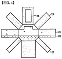
- FIG. 4 is a development view of a heat insulation part for a liquefied gas storage tank according to a third embodiment of the present invention.
- the heat insulation part for the liquefied gas storage tank according to the third embodiment shown in FIG. 4 is basically the same as the heat insulation part of the liquefied gas storage tank according to the second embodiment shown in FIG. 3 .
- the following description will focus on the difference between the heat insulation part according to the third embodiment shown in FIG. 3 .
- the heat insulation part for the liquefied gas storage tank according to the third embodiment further includes a seventh density region 28 formed at a lower portion of each of the front and back surfaces and the side surface thereof.
- a heat insulation panel disposed in the seventh density region 29 may have a higher density than a heat insulation panel disposed in the fourth density region 22.
- the heat insulation panel constituting the seventh density region 28 may have a density of about 210 kg/m 3 .
- the heat insulation part for the liquefied gas storage tank according to the third embodiment may be used in an offshore floating vessel having a storage tank storing liquefied gas as a cargo, such as an LNG carrier, as in the second embodiment.
- the heat insulation part according to the third embodiment may be used in a storage tank having a different capacity than the storage tank to which the heat insulation part according to the second embodiment is applied.
- the heat insulation part according to this embodiment further includes the seventh density region 28 in which a heat insulation panel having a relatively high density is disposed at portions of the front, side and back surfaces of the heat insulation part below the fourth density region 22, thereby exhibiting improved durability.
Landscapes
- Engineering & Computer Science (AREA)
- Mechanical Engineering (AREA)
- General Engineering & Computer Science (AREA)
- Physics & Mathematics (AREA)
- Thermal Sciences (AREA)
- Chemical & Material Sciences (AREA)
- Combustion & Propulsion (AREA)
- Ocean & Marine Engineering (AREA)
- Filling Or Discharging Of Gas Storage Vessels (AREA)
Abstract
Description
- The present invention relates to a liquefied gas storage tank including a heat insulation part and a method of arranging the heat insulation part, and more particularly, to a liquefied gas storage tank which includes a heat insulation part and can be manufactured at a reduced cost, and a method of arranging the heat insulation part.
- Since liquefied gas such as liquefied natural gas (LNG) is in a liquid state at a cryogenic temperature under atmospheric pressure, a separate tank capable of storing liquefied gas at a cryogenic temperature is required to transport the liquefied gas.
- Such a liquefied gas storage tank includes a heat insulation part to prevent liquefied gas from evaporating due to heat exchange with the outside.
- A liquefied gas storage tank is divided into an independent storage tank and a membrane-type storage tank depending on whether a heat insulation part directly receives a load of liquefied gas. In other words, in the independent storage tank, the heat insulation part does not directly receive the load of the liquefied gas, whereas, in the membrane-type storage tank, the heat insulation part directly receives the load of the liquefied gas.
- A membrane type storage tank is divided into a NO96 type storage tank and a Mark III type storage tank.
- A typical membrane-type storage tank is provided throughout the entire surface thereof with heat insulation panels having the same properties (i.e., the same densities) to achieve only the original purpose, i.e., insulation of liquefied gas from the outside.
- A liquefied gas storage tank is continuously impacted by sloshing. Here, "sloshing" refers to movement of a fluid with respect to a tank containing the fluid. During transportation of the fluid, sloshing in the tank can impact and damage to the tank. In other words, impact on the liquefied gas storage tank can be divided into (a) impact due to a load of liquefied gas and (b) impact due to sloshing of the liquefied gas.
- A membrane type storage tank, which includes a heat insulation part directly receiving a load of the liquefied gas, includes a portion heavily impacted by sloshing and a portion less impacted by sloshing. If heat insulation panels having the same strengths are disposed over the entire surface of the storage tank without considering this, (1) the portion of the storage tank heavily impacted by sloshing is relatively vulnerable, and (2) the portion of the storage tank less impacted by sloshing causes over-consumption of a heat insulation material.
- Therefore, embodiments of the present invention provide a membrane type storage tank which includes a heat insulation part, specifically optimally-disposed heat insulation panels, by taking into account liquefied gas-induced impact on the storage tank.
- In accordance with one aspect of the present invention, there is provided a liquefied gas storage tank including a heat insulation part, wherein the heat insulation part includes a plurality of regions in which heat insulation panels having different densities are disposed, respectively, the plurality of regions being divided based on impact on the storage tank due to a load of liquefied gas and sloshing of the liquefied gas.
- The plurality of regions may include: a first density region formed on a bottom surface of the storage tank; and a second density region formed on upper and side surfaces of the storage tank.
- A heat insulation panel disposed in the second density region may have a higher density than a heat insulation panel disposed in the first density region.
- The plurality of regions may include: a third density region formed on a bottom surface of the storage tank; a fourth density region formed on front, side and back surfaces of the storage tank; and a fifth density region formed on an upper surface of the storage tank.
- A heat insulation panel disposed in the fifth density region may have a higher density than a heat insulation panel disposed in the fourth density region, and a heat insulation panel disposed in the third density region may have a lower density than a heat insulation panel disposed in the fourth density region.
- The plurality of regions may further include: a sixth density region formed at a central portion on the upper surface of the storage tank to be surrounded by the fifth density region.
- A heat insulation panel disposed in the sixth density region may have a lower density than a heat insulation panel disposed in the fifth density region.
- The plurality of regions may further include: a seventh density region formed on a portion of each of the front, side and back surfaces of the storage tank below the fourth density region.
- A heat insulation panel disposed in the seventh density region may have a higher density than a heat insulation panel disposed in the fourth density region.
- The fourth density region may protrude upwardly toward the fifth density region.
- The liquefied gas storage tank may be a membrane-type storage tank.
- In accordance with another aspect of the present invention, there is provided a method of arranging a heat insulation part for a liquefied gas storage tank, including: dividing the heat insulation part into a first region under a load of liquefied gas; a second region impacted by sloshing of the liquefied gas; and a third region other than the first region and the second region; and disposing heat insulation panels in the first to third regions, respectively, such that a heat insulation panel disposed in the second region has a higher density than a heat insulation panel disposed in the first region and a heat insulation panel disposed in the third region has a higher density than the heat insulation panel disposed in the first region.
- The heat insulation part may include reinforced polyurethane foam (R-PUF).
- According to embodiments of the present invention, in a heat insulation part for a membrane-type storage tank, a heat insulation panel disposed at a portion of the storage tank heavily impacted by sloshing of liquefied gas has a different density than a heat insulation panel disposed at a portion of the storage tank less impacted by sloshing, thereby improving durability of the storage tank against impact due to liquefied gas.
- In addition, according to the embodiments of the present invention, a portion of the heat insulation part disposed at a portion of the storage tank less affected by a load of liquefied gas or impact due to the liquefied gas is composed of a heat insulation panel having a relatively low density, thereby enabling optimal use of a heat insulation material.
-
-
FIG. 1 is a perspective view of an exemplary liquefied gas storage tank to which the present invention is applied. -
FIG. 2 is a development view of a heat insulation part for a liquefied gas storage tank according to a first embodiment of the present invention. -
FIG. 3 is a development view of a heat insulation part for a liquefied gas storage tank according to a second embodiment of the present invention. -
FIG. 4 is a development view of a heat insulation part for a liquefied gas storage tank according to a third embodiment of the present invention. - Hereinafter, embodiments of the present invention will be described with reference to the accompanying drawings. However, it should be understood that the present invention is not limited to the following embodiments, and that various modifications and equivalent embodiments may be made by those skilled in the art. Therefore, the scope of the present invention is defined only by the claims.
-
FIG. 1 is a perspective view of an exemplary liquefied gas storage tank to which the present invention is applied. - Referring to
FIG. 1 , the liquefied gas storage tank 1 may be a membrane-type storage tank.FIGS. 2 to 4 are development views of the liquefied gas storage tank, respectively. InFIGS. 2 to 4 , different hatchings indicate different regions, specifically regions of a heat insulation part where heat insulation panels having different densities are disposed, respectively. - Although a front portion of the liquefied gas storage tank 1 is omitted to illustrate the interior of the liquefied gas storage tank 1 in
FIGS. 1 to 4 , it should be understood that, a front surface of a heat insulation part for a liquefied gas storage tank shown in each ofFIGS 2 to 4 is configured in the same manner as a back surface of the heat insulation part. - A heat insulation panel described below may be formed of reinforced polyurethane foam (R-PUF).
-
FIG. 2 is a development view of a heat insulation part for a liquefied gas storage tank according to a first embodiment of the present invention. - Referring to
FIG. 2 , the heat insulation part for the liquefied gas storage tank according to the first embodiment includes a bottom surface, an upper surface, side surfaces consisting of a right-side surface and a left-side surface, a front surface, and a back surface. In addition, the heat insulation part for the liquefied gas storage tank further includes a lower chamfered surface between each of the side surfaces and the bottom surface and an upper chamfered surface between each of the side surfaces and the upper surface. - The heat insulation part for the liquefied gas storage tank according to the first embodiment includes a
first density region 10 and asecond density region 12 based on the density of a heat insulation panel constituting the heat insulation part. The bottom surface of the heat insulation part for the liquefied gas storage tank corresponds to thefirst density region 10, and the other surfaces of the heat insulation part, including the upper and lower chamfered surfaces, correspond to thesecond density region 12. Here, a heat insulation panel disposed in thesecond density region 12 may have a higher density than a heat insulation panel disposed in thefirst density region 10. - For example, the heat insulation panel disposed in the
first density region 10 may have a density of about 130 kg/m3, and the heat insulation panel disposed in thesecond density region 12 may have a density of about 210 kg/m3. - The heat insulation part for the liquefied gas storage tank according to the first embodiment may be used in an offshore floating vessel fueled by liquefied gas. As the offshore floating vessel fueled by liquefied gas is operated, the amount of the liquefied gas in a liquefied gas storage tank of the offshore floating vessel is gradually decreased. Thus, the storage tank is impacted by sloshing at varying portions thereof during operation of the offshore floating vessel. In other words, in an early stage of operation in which a relatively large amount of the liquefied gas is stored in the liquefied gas storage tank, an upper portion of each of front and back surfaces, side surfaces, an upper chamfered surface, and an upper surface of the liquefied gas storage tank are impacted by sloshing, whereas, in a later stage of operation in which the amount of the liquefied gas in the liquefied gas storage tank is decreased, a lower portion of each of the front and back surfaces, the side surfaces, and a lower chamfered surface of the liquefied gas storage tank are impacted by sloshing.
- On the other hand, factors of liquefied gas-induced impact on the liquefied gas storage tank are mainly divided into (a) the load of the liquefied gas on a bottom surface of the liquefied gas storage tank and (b) sloshing of the liquefied gas against the upper surface, the side surfaces, the front surface, the back surface, or the upper and lower chamfered surfaces of the storage tank. Generally, the impact on the storage tank due to (b) is greater than the impact on the storage tank due to (a). Accordingly, the heat insulation panel disposed in the
first density region 10 may have a relatively low density, whereas the heat insulation panel disposed in thesecond density region 12 may have a relatively high density. -
FIG. 3 is a development view of a heat insulation part for a liquefied gas storage tank according to a second embodiment of the present invention. - Referring to
FIG. 3 , the heat insulation part for the liquefied gas storage tank according to the second embodiment of the present invention includes different density regions than the heat insulation part according to the first embodiment. In other words, a bottom surface and a lower chamfered surface of the heat insulation part correspond to athird density region 20, a central portion and lower portion of each of front and back surfaces and a side surface of the heat insulation part correspond to afourth density region 22, and at least a portion of the upper surface, an upper portion of each of the front and back surfaces, and an upper chamfered surface of the heat insulation part correspond to afifth density region 24. In addition, a central portion of the upper surface may correspond to asixth density region 26, and thus the rest of the upper surface excluding the central portion may correspond to thefifth density region 24. - As shown in
FIG. 3 , the central portion of each of the front and back surfaces, corresponding to thefourth density region 22, may upwardly protrude toward the upper portion of each of the front and back surfaces, that is, thefifth density region 24; thesixth density region 26 may be formed in a rectangular shape at the central portion of the upper surface; and thefifth density region 24 may surround the rectangularsixth density region 26. - A heat insulation panel disposed in the
fifth density region 24 may have a higher density than a heat insulation panel disposed in thefourth density region 22, and a heat insulation panel disposed in thefourth density region 22 may have a higher density than a heat insulation panel disposed in thethird density region 20. In addition, a heat insulation panel disposed in thefifth density region 24 may have a higher density than a heat insulation panel disposed in thesixth density region 26. - For example, the heat insulation panel disposed in the
third density region 20 may have a density of about 100 kg/m3, the heat insulation panel in each of thefourth density region 22 and thesixth density region 26 may have a density of about 130 kg/m3, and the heat insulation panel disposed in thefifth density region 24 may have a density of about 210 kg/m3. - The heat insulation part for the liquefied gas storage tank according to the second embodiment may be used in an offshore floating vessel having a storage tank storing liquefied gas as a cargo, such as an LNG carrier. Unlike the liquefied gas storage tank according to the first embodiment, a liquefied gas storage tank of the offshore floating vessel storing or carrying a liquefied gas cargo is fully filled with liquefied gas or is empty. Thus, in the second embodiment of the present invention, it is not necessary that the entirety of the heat insulation part excluding the bottom surface be composed of a heat insulation panel having a relatively high density.
- In the second embodiment, a heat insulation panel constituting at least a portion of the upper portion of each of the front and back surfaces, at least a portion of the upper surface, and the upper chamfered surface of the heat insulation part, which are heavily impacted by sloshing, may have a relatively high density; a heat insulation panel constituting the central portion and lower portion of each of the front and back surfaces, the side surfaces, and the central portion of the upper surface of the heat insulation part, which are relatively less impacted by sloshing, may have a relatively intermediate density; and a heat insulation panel constituting the bottom surface and the lower chamfered surface of the heat insulation part, which are mainly impacted by a load of liquefied gas while being impacted little by sloshing, may have a relatively low density.
- An edge of the upper surface of the heat insulation part is relatively heavily impacted by sloshing, whereas the central portion of the upper surface is relatively less impact by sloshing. Accordingly, a heat insulation panel constituting the edge of the upper surface may have a relatively high density, and a heat insulation panel constituting the central portion of the upper surface may have a relatively low density.
- Generally, a heat insulation panel attached to the liquefied gas storage tank has a rectangular shape. According to the present invention, the central portion of each of the front and back surfaces of the heat insulation part, corresponding to the
fourth density region 22, may protrude in an angular rectangular shape toward thefifth density region 24, as shown inFIG. 3 , such that the effects of the present invention can be achieved without a separate heat insulation panel having a shape other than a rectangular shape. In addition, the central portion of the upper surface of the heat insulation part, corresponding to thesixth density region 26, may have a rectangular shape such that the effects of the present invention can be achieved without a need to provide a separate heat insulation panel. -
FIG. 4 is a development view of a heat insulation part for a liquefied gas storage tank according to a third embodiment of the present invention. - The heat insulation part for the liquefied gas storage tank according to the third embodiment shown in
FIG. 4 is basically the same as the heat insulation part of the liquefied gas storage tank according to the second embodiment shown inFIG. 3 . Thus, the following description will focus on the difference between the heat insulation part according to the third embodiment shown inFIG. 3 . - Referring to
FIG. 4 , the heat insulation part for the liquefied gas storage tank according to the third embodiment further includes aseventh density region 28 formed at a lower portion of each of the front and back surfaces and the side surface thereof. A heat insulation panel disposed in the seventh density region 29 may have a higher density than a heat insulation panel disposed in thefourth density region 22. For example, the heat insulation panel constituting theseventh density region 28 may have a density of about 210 kg/m3. - The heat insulation part for the liquefied gas storage tank according to the third embodiment may be used in an offshore floating vessel having a storage tank storing liquefied gas as a cargo, such as an LNG carrier, as in the second embodiment. However, the heat insulation part according to the third embodiment may be used in a storage tank having a different capacity than the storage tank to which the heat insulation part according to the second embodiment is applied.
- When a relatively small amount of liquefied gas is stored in the storage tank, the lower portion of each of the front and back surfaces and the side surfaces of the heat insulation part can be heavily impacted by sloshing during carriage of liquefied gas. Accordingly, the heat insulation part according to this embodiment further includes the
seventh density region 28 in which a heat insulation panel having a relatively high density is disposed at portions of the front, side and back surfaces of the heat insulation part below thefourth density region 22, thereby exhibiting improved durability. - Although some embodiments have been described herein, it should be understood that these embodiments are provided for illustration only and are not to be construed in any way as limiting the present invention, and that various modifications, changes, alterations, and equivalent embodiments can be made by those skilled in the art without departing from the spirit and scope of the invention. The scope of the present invention should be defined by the appended claims and equivalents thereof.
Claims (13)
- A liquefied gas storage tank comprising a heat insulation part,
wherein the heat insulation part comprises a plurality of regions in which heat insulation panels having different densities are disposed, respectively, the plurality of regions being divided based on impact on the storage tank due to a load of liquefied gas and sloshing of the liquefied gas. - The liquefied gas storage tank according to claim 1, wherein the plurality of regions comprises: a first density region formed on a bottom surface of the storage tank; and a second density region formed on upper and side surfaces of the storage tank.
- The liquefied gas storage tank according to claim 2, wherein a heat insulation panel disposed in the second density region has a higher density than a heat insulation panel disposed in the first density region.
- The liquefied gas storage tank according to claim 1, wherein the plurality of regions comprises: a third density region formed on a bottom surface of the storage tank; a fourth density region formed on front, side and back surfaces of the storage tank; and a fifth density region formed on an upper surface of the storage tank.
- The liquefied gas storage tank according to claim 4, wherein a heat insulation panel disposed in the fifth density region has a higher density than a heat insulation panel disposed in the fourth density region, and a heat insulation panel disposed in the third density region has a lower density than a heat insulation panel disposed in the fourth density region.
- The liquefied gas storage tank according to claim 4, wherein the plurality of regions further comprises: a sixth density region formed at a central portion on the upper surface of the storage tank to be surrounded by the fifth density region.
- The liquefied gas storage tank according to claim 6, wherein a heat insulation panel disposed in the sixth density region has a lower density than a heat insulation panel disposed in the fifth density region.
- The liquefied gas storage tank according to claim 6, wherein the plurality of regions further comprises: a seventh density region formed at a portion of each of the front, side and back surfaces of the storage tank under the fourth density region.
- The liquefied gas storage tank according to claim 8, wherein a heat insulation panel disposed in the seventh density region has a higher density than a heat insulation panel disposed in the fourth density region.
- The liquefied gas storage tank according to claim 4, wherein the fourth density region upwardly protrudes toward the fifth density region.
- The liquefied gas storage tank according to claim 1, wherein the liquefied gas storage tank is a membrane-type storage tank.
- A method of arranging a heat insulation part for a liquefied gas storage tank, comprising:dividing the heat insulation part into a first region under a load of liquefied gas; a second region impacted by sloshing of the liquefied gas; and a third region other than the first region and the second region; anddisposing heat insulation panels in the first to third regions, respectively, such that a heat insulation panel disposed in the second region has a higher density than a heat insulation panel disposed in the first region and a heat insulation panel disposed in the third region has a higher density than the heat insulation panel disposed in the first region.
- The method according to claim 12, wherein the heat insulation part comprises reinforced polyurethane foam (R-PUF).
Applications Claiming Priority (2)
| Application Number | Priority Date | Filing Date | Title |
|---|---|---|---|
| KR1020150099001A KR102384711B1 (en) | 2015-07-13 | 2015-07-13 | Liquefied storage tank including heat insulation part |
| PCT/KR2016/004220 WO2017010661A1 (en) | 2015-07-13 | 2016-04-22 | Liquefied gas storage tank having insulation parts and method for arranging insulation parts |
Publications (3)
| Publication Number | Publication Date |
|---|---|
| EP3324095A1 true EP3324095A1 (en) | 2018-05-23 |
| EP3324095A4 EP3324095A4 (en) | 2019-02-27 |
| EP3324095B1 EP3324095B1 (en) | 2020-07-15 |
Family
ID=57757899
Family Applications (1)
| Application Number | Title | Priority Date | Filing Date |
|---|---|---|---|
| EP16824578.5A Active EP3324095B1 (en) | 2015-07-13 | 2016-04-22 | Liquefied gas storage tank having insulation parts and method for arranging insulation parts |
Country Status (7)
| Country | Link |
|---|---|
| US (1) | US11428369B2 (en) |
| EP (1) | EP3324095B1 (en) |
| JP (1) | JP6546344B2 (en) |
| KR (1) | KR102384711B1 (en) |
| CN (1) | CN108139025B (en) |
| ES (1) | ES2820825T3 (en) |
| WO (1) | WO2017010661A1 (en) |
Families Citing this family (6)
| Publication number | Priority date | Publication date | Assignee | Title |
|---|---|---|---|---|
| KR102384711B1 (en) * | 2015-07-13 | 2022-04-08 | 대우조선해양 주식회사 | Liquefied storage tank including heat insulation part |
| JP7233024B2 (en) * | 2019-04-15 | 2023-03-06 | パナソニックIpマネジメント株式会社 | heat pump heat source machine |
| KR102862976B1 (en) * | 2020-09-14 | 2025-09-23 | 한화오션 주식회사 | Insulation system for liquified gas storage tank and contruction method thereof |
| KR102772049B1 (en) | 2022-10-21 | 2025-02-25 | 하이리움산업(주) | Liquefier insulation system and liquefier applying the same |
| KR102868040B1 (en) | 2023-03-24 | 2025-10-14 | 하이리움산업(주) | Non-contact liquefaction system and method |
| KR102609570B1 (en) | 2023-05-11 | 2023-12-01 | 박원희 | Treatment device with a needle unit and driving method tereof |
Family Cites Families (54)
| Publication number | Priority date | Publication date | Assignee | Title |
|---|---|---|---|---|
| US2994452A (en) * | 1954-08-02 | 1961-08-01 | Conch Int Methane Ltd | Insulated tank for liquefied hydrocarbons and the like with loose membranous lining therefor |
| US2896416A (en) * | 1957-08-05 | 1959-07-28 | Constock Int Methane Ltd | Means for the transportation and storage of cold boiling liquefied hydrocarbon gas |
| GB833613A (en) * | 1958-01-13 | 1960-04-27 | British Oxygen Res And Dev Ltd | Thermally insulated storage vessels |
| NL126255C (en) * | 1960-05-21 | |||
| US3367492A (en) * | 1964-09-03 | 1968-02-06 | Exxon Research Engineering Co | Insulation system |
| GB1110366A (en) * | 1966-03-21 | 1968-04-18 | Conch Int Methane Ltd | Improvements in and relating to containers for liquefied gases |
| GB1173424A (en) * | 1966-11-02 | 1969-12-10 | Shell Int Research | Improvements in or relating to Thermally Insulated Containers |
| US3489311A (en) * | 1967-05-25 | 1970-01-13 | Aerojet General Co | Tanks for storage of liquefied gas |
| GB1214055A (en) * | 1968-02-21 | 1970-12-02 | Conch Ocean Ltd | Improvement in tanker for carrying liquefied gases |
| US3547047A (en) * | 1968-10-31 | 1970-12-15 | Acf Ind Inc | Insulated railway tank car and method of forming same |
| US3595424A (en) | 1969-02-24 | 1971-07-27 | Conch Int Methane Ltd | Containers for liquefied gases |
| US3655086A (en) * | 1970-10-09 | 1972-04-11 | Cryotan Inc | Receptacles for the storage of liquefied gases at cryogenic temperatures |
| CA943883A (en) * | 1970-10-14 | 1974-03-19 | Conch International Methane Limited | Containers for liquefied gases |
| US3757982A (en) * | 1971-06-11 | 1973-09-11 | North American Rockwell | Thermally insulated container |
| US3895159A (en) * | 1972-11-13 | 1975-07-15 | Ataka & Company Ltd | Cryogenic insulating material |
| NL7302527A (en) * | 1973-02-23 | 1974-08-27 | ||
| US4009236A (en) * | 1973-06-12 | 1977-02-22 | Mitsubishi Jukogyo Kabushiki Kaisha | Method of making insulated tank for low temperature service |
| US3929247A (en) * | 1973-07-11 | 1975-12-30 | Kaiser Aluminium Chem Corp | Cryogenic tank |
| US3931908A (en) * | 1973-08-02 | 1976-01-13 | Kaiser Aluminum & Chemical Corporation | Insulated tank |
| GB1442351A (en) * | 1973-09-08 | 1976-07-14 | Conch Int Methane Ltd | Storage containers for liquids at non-ambient temperatures |
| US4032608A (en) | 1974-07-12 | 1977-06-28 | Kaiser Aluminum & Chemical Corporation | Cryogenic liquid containment method |
| US3927788A (en) * | 1974-07-12 | 1975-12-23 | Kaiser Aluminium Chem Corp | Cryogenic liquid containment system |
| US3993213A (en) * | 1975-09-04 | 1976-11-23 | Mcdonnell Douglas Corporation | Thermally insulated cryogenic container |
| US4170952A (en) * | 1976-03-09 | 1979-10-16 | Mcdonnell Douglas Corporation | Cryogenic insulation system |
| JPS52155419A (en) * | 1976-06-18 | 1977-12-23 | Bridgestone Liquefied Gas Co | Diaphragm type tanks for storing cryogenic liquefied gas |
| US4135465A (en) * | 1977-01-11 | 1979-01-23 | Dudley Fred T | Tank for fuel tanker |
| GB1589385A (en) * | 1977-04-07 | 1981-05-13 | Technigaz | Thermally insulating fluid-tight composite wall prefabricated elements for constructing the same and method of constructing said wall |
| US4452162A (en) * | 1978-05-26 | 1984-06-05 | Mcdonnell Douglas Corporation | Corner structure for cryogenic insulation system |
| JPS62194098A (en) * | 1986-02-20 | 1987-08-26 | Nippon Kokan Kk <Nkk> | Roof insulation structure of low temperature storage tank |
| US5476189A (en) * | 1993-12-03 | 1995-12-19 | Duvall; Paul F. | Pressure vessel with damage mitigating system |
| US5797513A (en) * | 1996-02-29 | 1998-08-25 | Owens Corning Fiberglas Technology, Inc. | Insulated vessels |
| US5727492A (en) * | 1996-09-16 | 1998-03-17 | Marinex International Inc. | Liquefied natural gas tank and containment system |
| FR2800349B1 (en) * | 1999-10-27 | 2002-01-18 | Bouygues Offshore | LIQUEFIED GAS STORAGE BARGE WITH FLOATING CONCRETE STRUCTURE |
| FR2813111B1 (en) * | 2000-08-18 | 2002-11-29 | Gaz Transport & Technigaz | WATERPROOF AND THERMALLY INSULATING TANK IMPROVED LONGITUDINAL AREAS |
| US7469651B2 (en) * | 2004-07-02 | 2008-12-30 | Exxonmobil Upstream Research Company | Lng sloshing impact reduction system |
| DE602004023657D1 (en) * | 2004-08-04 | 2009-11-26 | Ootmarsum Harry Robert Van | MEMORY CONTAINER FOR COLD LIQUIDS AND METHOD FOR INSTALLING A HEAT INSULATION SYSTEM IN SUCH A CONTAINER |
| NL1028679C2 (en) * | 2005-04-01 | 2006-10-09 | Orca V O F | Ship with liquid transport tanks equipped with deformation sensors. |
| KR100553017B1 (en) | 2005-04-20 | 2006-02-15 | 이성욱 | Second gas barrier bonding method using heating pad |
| KR100649316B1 (en) * | 2006-09-01 | 2006-11-24 | 한국가스공사 | Anchor Structure of LNG Storage Tank |
| US9950830B2 (en) * | 2007-04-23 | 2018-04-24 | Coldkeepers, Llc | Insulated liners and containers |
| KR20090131329A (en) | 2008-06-18 | 2009-12-29 | 대우조선해양 주식회사 | A floating offshore structure having a liquefied gas storage tank and the liquefied gas storage tank |
| KR101215629B1 (en) * | 2008-06-20 | 2012-12-26 | 삼성중공업 주식회사 | Insulation panel for corner area of lng cargo containment system |
| FR2945511B1 (en) * | 2009-05-14 | 2011-07-22 | Saipem Sa | VESSEL OR FLOATING SUPPORT EQUIPPED WITH A DEVICE FOR DETECTING THE MOVEMENTS OF LIQUID CARENES |
| KR101215473B1 (en) * | 2010-06-07 | 2012-12-26 | 삼성중공업 주식회사 | Insulation structure of Cargo hold |
| JP6179043B2 (en) * | 2011-07-25 | 2017-08-16 | 信吉 森元 | Method for manufacturing liquefied natural gas carrier |
| US9376049B2 (en) * | 2011-08-22 | 2016-06-28 | Tranzgaz Inc. | Method of fabricating type 4 cylinders and arranging in transportation housings for transport of gaseous fluids |
| KR101375263B1 (en) * | 2011-12-01 | 2014-03-18 | 삼성중공업 주식회사 | Insulation Board Arrangement Structure and Method of Liquefied Natural Gas Storage Tank |
| KR101337644B1 (en) | 2011-12-16 | 2013-12-16 | 삼성중공업 주식회사 | Insulation structure and liquefied natural gas storage tank including the same |
| KR101919164B1 (en) | 2013-04-05 | 2018-11-16 | 현대중공업 주식회사 | Cargo tank for extremely low temperature substance carrier |
| DE212015000147U1 (en) * | 2014-06-04 | 2017-01-09 | Panasonic Intellectual Property Management Co., Ltd. | Thermal insulation and heat-insulating container |
| KR102384711B1 (en) * | 2015-07-13 | 2022-04-08 | 대우조선해양 주식회사 | Liquefied storage tank including heat insulation part |
| FR3050008B1 (en) * | 2016-04-11 | 2018-04-27 | Gaztransport Et Technigaz | WATERPROOF TANK WITH CORRUGATED SEALING MEMBRANES |
| KR102020965B1 (en) * | 2017-12-29 | 2019-09-11 | 대우조선해양 주식회사 | Membrane connecting structure and liquefied gas storage tank including the structure |
| US11472514B2 (en) * | 2019-01-02 | 2022-10-18 | Daewoo Shipbuilding & Marine Engineering Co., Ltd. | Membrane type insulation system for cryogenic LNG carrier cargo tank and liquefied gas fuel container |
-
2015
- 2015-07-13 KR KR1020150099001A patent/KR102384711B1/en active Active
-
2016
- 2016-04-22 WO PCT/KR2016/004220 patent/WO2017010661A1/en not_active Ceased
- 2016-04-22 ES ES16824578T patent/ES2820825T3/en active Active
- 2016-04-22 JP JP2018521155A patent/JP6546344B2/en active Active
- 2016-04-22 EP EP16824578.5A patent/EP3324095B1/en active Active
- 2016-04-22 US US15/744,708 patent/US11428369B2/en active Active
- 2016-04-22 CN CN201680052776.5A patent/CN108139025B/en active Active
Also Published As
| Publication number | Publication date |
|---|---|
| CN108139025A (en) | 2018-06-08 |
| US11428369B2 (en) | 2022-08-30 |
| JP6546344B2 (en) | 2019-07-17 |
| WO2017010661A1 (en) | 2017-01-19 |
| EP3324095B1 (en) | 2020-07-15 |
| KR20170007945A (en) | 2017-01-23 |
| US20180209586A1 (en) | 2018-07-26 |
| ES2820825T3 (en) | 2021-04-22 |
| CN108139025B (en) | 2020-03-13 |
| EP3324095A4 (en) | 2019-02-27 |
| JP2018525592A (en) | 2018-09-06 |
| KR102384711B1 (en) | 2022-04-08 |
Similar Documents
| Publication | Publication Date | Title |
|---|---|---|
| EP3324095B1 (en) | Liquefied gas storage tank having insulation parts and method for arranging insulation parts | |
| KR20130046642A (en) | Lng cargo containment | |
| KR20160007976A (en) | Liquefied gas storage tank and marine structure including the same | |
| KR101215599B1 (en) | Self-supporting cargo tank for liquefied natural gas and liquefied natural gas ship having the same | |
| KR20130113134A (en) | Lng cargo containment | |
| KR20100069375A (en) | Insulation panel for lng tank | |
| KR101012644B1 (en) | Insulation box for NNG storage tank | |
| KR20110039722A (en) | Fixed structure of independent storage tank | |
| KR20160034517A (en) | Liquefied gas storage tank and marine structure including the same | |
| KR20100003614U (en) | Liquefied gas storage tank with sloshing inhibiting means | |
| KR20120131302A (en) | Liquefied gas storage tank and Ship including the same | |
| KR20170064782A (en) | Elastic supporting apparatus of lng cargo and lng cargo comprising the same | |
| KR102576201B1 (en) | Insulation Structure of LNG Storage Tank | |
| KR101433101B1 (en) | Insulation structure of lng cargo hold | |
| KR102742185B1 (en) | Insulation Box of Liquefied Gas Storage Tank | |
| KR100961866B1 (en) | A floating offshore structure having a liquefied gas storage tank and the liquefied gas storage tank | |
| KR101022408B1 (en) | Offshore structure having a plurality of storage tanks having different strengths and a method of manufacturing the offshore structure | |
| KR101703387B1 (en) | A Liquid Storage Tank and Manufacturing Method | |
| KR102779533B1 (en) | Leakage liquid collection apparatus for lng cargo tank and offshore structure including the same | |
| KR102608693B1 (en) | Lower barrier structure of independence type storage tank | |
| KR101324305B1 (en) | Cargo tank for storing liquefied gas | |
| KR20180073121A (en) | Insulation system for membrane type lng cargo tank | |
| KR200487359Y1 (en) | Membrane type insulation box structure for storing liquid gas in ship | |
| KR20090080464A (en) | Vessels or floating offshore structures with multiple storage tanks of different strength | |
| KR20160005513A (en) | Insulation box of lng storage tank |
Legal Events
| Date | Code | Title | Description |
|---|---|---|---|
| STAA | Information on the status of an ep patent application or granted ep patent |
Free format text: STATUS: THE INTERNATIONAL PUBLICATION HAS BEEN MADE |
|
| PUAI | Public reference made under article 153(3) epc to a published international application that has entered the european phase |
Free format text: ORIGINAL CODE: 0009012 |
|
| STAA | Information on the status of an ep patent application or granted ep patent |
Free format text: STATUS: REQUEST FOR EXAMINATION WAS MADE |
|
| 17P | Request for examination filed |
Effective date: 20180112 |
|
| AK | Designated contracting states |
Kind code of ref document: A1 Designated state(s): AL AT BE BG CH CY CZ DE DK EE ES FI FR GB GR HR HU IE IS IT LI LT LU LV MC MK MT NL NO PL PT RO RS SE SI SK SM TR |
|
| AX | Request for extension of the european patent |
Extension state: BA ME |
|
| DAV | Request for validation of the european patent (deleted) | ||
| DAX | Request for extension of the european patent (deleted) | ||
| A4 | Supplementary search report drawn up and despatched |
Effective date: 20190124 |
|
| RIC1 | Information provided on ipc code assigned before grant |
Ipc: F17C 1/12 20060101AFI20190118BHEP Ipc: B63B 25/16 20060101ALI20190118BHEP Ipc: F17C 3/02 20060101ALI20190118BHEP |
|
| GRAP | Despatch of communication of intention to grant a patent |
Free format text: ORIGINAL CODE: EPIDOSNIGR1 |
|
| STAA | Information on the status of an ep patent application or granted ep patent |
Free format text: STATUS: GRANT OF PATENT IS INTENDED |
|
| INTG | Intention to grant announced |
Effective date: 20200206 |
|
| GRAS | Grant fee paid |
Free format text: ORIGINAL CODE: EPIDOSNIGR3 |
|
| GRAA | (expected) grant |
Free format text: ORIGINAL CODE: 0009210 |
|
| STAA | Information on the status of an ep patent application or granted ep patent |
Free format text: STATUS: THE PATENT HAS BEEN GRANTED |
|
| AK | Designated contracting states |
Kind code of ref document: B1 Designated state(s): AL AT BE BG CH CY CZ DE DK EE ES FI FR GB GR HR HU IE IS IT LI LT LU LV MC MK MT NL NO PL PT RO RS SE SI SK SM TR |
|
| REG | Reference to a national code |
Ref country code: CH Ref legal event code: EP Ref country code: GB Ref legal event code: FG4D |
|
| REG | Reference to a national code |
Ref country code: IE Ref legal event code: FG4D |
|
| REG | Reference to a national code |
Ref country code: DE Ref legal event code: R096 Ref document number: 602016040106 Country of ref document: DE |
|
| REG | Reference to a national code |
Ref country code: AT Ref legal event code: REF Ref document number: 1291427 Country of ref document: AT Kind code of ref document: T Effective date: 20200815 |
|
| REG | Reference to a national code |
Ref country code: NO Ref legal event code: T2 Effective date: 20200715 |
|
| REG | Reference to a national code |
Ref country code: LT Ref legal event code: MG4D |
|
| REG | Reference to a national code |
Ref country code: GR Ref legal event code: EP Ref document number: 20200402751 Country of ref document: GR Effective date: 20201116 |
|
| REG | Reference to a national code |
Ref country code: AT Ref legal event code: MK05 Ref document number: 1291427 Country of ref document: AT Kind code of ref document: T Effective date: 20200715 |
|
| REG | Reference to a national code |
Ref country code: NL Ref legal event code: MP Effective date: 20200715 |
|
| PG25 | Lapsed in a contracting state [announced via postgrant information from national office to epo] |
Ref country code: LT Free format text: LAPSE BECAUSE OF FAILURE TO SUBMIT A TRANSLATION OF THE DESCRIPTION OR TO PAY THE FEE WITHIN THE PRESCRIBED TIME-LIMIT Effective date: 20200715 Ref country code: PT Free format text: LAPSE BECAUSE OF FAILURE TO SUBMIT A TRANSLATION OF THE DESCRIPTION OR TO PAY THE FEE WITHIN THE PRESCRIBED TIME-LIMIT Effective date: 20201116 Ref country code: HR Free format text: LAPSE BECAUSE OF FAILURE TO SUBMIT A TRANSLATION OF THE DESCRIPTION OR TO PAY THE FEE WITHIN THE PRESCRIBED TIME-LIMIT Effective date: 20200715 Ref country code: SE Free format text: LAPSE BECAUSE OF FAILURE TO SUBMIT A TRANSLATION OF THE DESCRIPTION OR TO PAY THE FEE WITHIN THE PRESCRIBED TIME-LIMIT Effective date: 20200715 Ref country code: BG Free format text: LAPSE BECAUSE OF FAILURE TO SUBMIT A TRANSLATION OF THE DESCRIPTION OR TO PAY THE FEE WITHIN THE PRESCRIBED TIME-LIMIT Effective date: 20201015 Ref country code: AT Free format text: LAPSE BECAUSE OF FAILURE TO SUBMIT A TRANSLATION OF THE DESCRIPTION OR TO PAY THE FEE WITHIN THE PRESCRIBED TIME-LIMIT Effective date: 20200715 Ref country code: FI Free format text: LAPSE BECAUSE OF FAILURE TO SUBMIT A TRANSLATION OF THE DESCRIPTION OR TO PAY THE FEE WITHIN THE PRESCRIBED TIME-LIMIT Effective date: 20200715 |
|
| PG25 | Lapsed in a contracting state [announced via postgrant information from national office to epo] |
Ref country code: RS Free format text: LAPSE BECAUSE OF FAILURE TO SUBMIT A TRANSLATION OF THE DESCRIPTION OR TO PAY THE FEE WITHIN THE PRESCRIBED TIME-LIMIT Effective date: 20200715 Ref country code: LV Free format text: LAPSE BECAUSE OF FAILURE TO SUBMIT A TRANSLATION OF THE DESCRIPTION OR TO PAY THE FEE WITHIN THE PRESCRIBED TIME-LIMIT Effective date: 20200715 Ref country code: PL Free format text: LAPSE BECAUSE OF FAILURE TO SUBMIT A TRANSLATION OF THE DESCRIPTION OR TO PAY THE FEE WITHIN THE PRESCRIBED TIME-LIMIT Effective date: 20200715 Ref country code: IS Free format text: LAPSE BECAUSE OF FAILURE TO SUBMIT A TRANSLATION OF THE DESCRIPTION OR TO PAY THE FEE WITHIN THE PRESCRIBED TIME-LIMIT Effective date: 20201115 |
|
| PG25 | Lapsed in a contracting state [announced via postgrant information from national office to epo] |
Ref country code: NL Free format text: LAPSE BECAUSE OF FAILURE TO SUBMIT A TRANSLATION OF THE DESCRIPTION OR TO PAY THE FEE WITHIN THE PRESCRIBED TIME-LIMIT Effective date: 20200715 |
|
| REG | Reference to a national code |
Ref country code: DE Ref legal event code: R097 Ref document number: 602016040106 Country of ref document: DE |
|
| REG | Reference to a national code |
Ref country code: ES Ref legal event code: FG2A Ref document number: 2820825 Country of ref document: ES Kind code of ref document: T3 Effective date: 20210422 |
|
| PG25 | Lapsed in a contracting state [announced via postgrant information from national office to epo] |
Ref country code: IT Free format text: LAPSE BECAUSE OF FAILURE TO SUBMIT A TRANSLATION OF THE DESCRIPTION OR TO PAY THE FEE WITHIN THE PRESCRIBED TIME-LIMIT Effective date: 20200715 Ref country code: EE Free format text: LAPSE BECAUSE OF FAILURE TO SUBMIT A TRANSLATION OF THE DESCRIPTION OR TO PAY THE FEE WITHIN THE PRESCRIBED TIME-LIMIT Effective date: 20200715 Ref country code: SM Free format text: LAPSE BECAUSE OF FAILURE TO SUBMIT A TRANSLATION OF THE DESCRIPTION OR TO PAY THE FEE WITHIN THE PRESCRIBED TIME-LIMIT Effective date: 20200715 Ref country code: RO Free format text: LAPSE BECAUSE OF FAILURE TO SUBMIT A TRANSLATION OF THE DESCRIPTION OR TO PAY THE FEE WITHIN THE PRESCRIBED TIME-LIMIT Effective date: 20200715 Ref country code: CZ Free format text: LAPSE BECAUSE OF FAILURE TO SUBMIT A TRANSLATION OF THE DESCRIPTION OR TO PAY THE FEE WITHIN THE PRESCRIBED TIME-LIMIT Effective date: 20200715 Ref country code: DK Free format text: LAPSE BECAUSE OF FAILURE TO SUBMIT A TRANSLATION OF THE DESCRIPTION OR TO PAY THE FEE WITHIN THE PRESCRIBED TIME-LIMIT Effective date: 20200715 |
|
| PLBE | No opposition filed within time limit |
Free format text: ORIGINAL CODE: 0009261 |
|
| STAA | Information on the status of an ep patent application or granted ep patent |
Free format text: STATUS: NO OPPOSITION FILED WITHIN TIME LIMIT |
|
| PG25 | Lapsed in a contracting state [announced via postgrant information from national office to epo] |
Ref country code: AL Free format text: LAPSE BECAUSE OF FAILURE TO SUBMIT A TRANSLATION OF THE DESCRIPTION OR TO PAY THE FEE WITHIN THE PRESCRIBED TIME-LIMIT Effective date: 20200715 |
|
| 26N | No opposition filed |
Effective date: 20210416 |
|
| PG25 | Lapsed in a contracting state [announced via postgrant information from national office to epo] |
Ref country code: SK Free format text: LAPSE BECAUSE OF FAILURE TO SUBMIT A TRANSLATION OF THE DESCRIPTION OR TO PAY THE FEE WITHIN THE PRESCRIBED TIME-LIMIT Effective date: 20200715 |
|
| PG25 | Lapsed in a contracting state [announced via postgrant information from national office to epo] |
Ref country code: SI Free format text: LAPSE BECAUSE OF FAILURE TO SUBMIT A TRANSLATION OF THE DESCRIPTION OR TO PAY THE FEE WITHIN THE PRESCRIBED TIME-LIMIT Effective date: 20200715 |
|
| REG | Reference to a national code |
Ref country code: DE Ref legal event code: R119 Ref document number: 602016040106 Country of ref document: DE |
|
| PG25 | Lapsed in a contracting state [announced via postgrant information from national office to epo] |
Ref country code: MC Free format text: LAPSE BECAUSE OF FAILURE TO SUBMIT A TRANSLATION OF THE DESCRIPTION OR TO PAY THE FEE WITHIN THE PRESCRIBED TIME-LIMIT Effective date: 20200715 |
|
| GBPC | Gb: european patent ceased through non-payment of renewal fee |
Effective date: 20210422 |
|
| PG25 | Lapsed in a contracting state [announced via postgrant information from national office to epo] |
Ref country code: LU Free format text: LAPSE BECAUSE OF NON-PAYMENT OF DUE FEES Effective date: 20210422 |
|
| REG | Reference to a national code |
Ref country code: BE Ref legal event code: MM Effective date: 20210430 |
|
| PG25 | Lapsed in a contracting state [announced via postgrant information from national office to epo] |
Ref country code: DE Free format text: LAPSE BECAUSE OF NON-PAYMENT OF DUE FEES Effective date: 20211103 Ref country code: CH Free format text: LAPSE BECAUSE OF NON-PAYMENT OF DUE FEES Effective date: 20210430 Ref country code: LI Free format text: LAPSE BECAUSE OF NON-PAYMENT OF DUE FEES Effective date: 20210430 Ref country code: GB Free format text: LAPSE BECAUSE OF NON-PAYMENT OF DUE FEES Effective date: 20210422 |
|
| PG25 | Lapsed in a contracting state [announced via postgrant information from national office to epo] |
Ref country code: IE Free format text: LAPSE BECAUSE OF NON-PAYMENT OF DUE FEES Effective date: 20210422 |
|
| PG25 | Lapsed in a contracting state [announced via postgrant information from national office to epo] |
Ref country code: IS Free format text: LAPSE BECAUSE OF FAILURE TO SUBMIT A TRANSLATION OF THE DESCRIPTION OR TO PAY THE FEE WITHIN THE PRESCRIBED TIME-LIMIT Effective date: 20201115 |
|
| PG25 | Lapsed in a contracting state [announced via postgrant information from national office to epo] |
Ref country code: BE Free format text: LAPSE BECAUSE OF NON-PAYMENT OF DUE FEES Effective date: 20210430 |
|
| PG25 | Lapsed in a contracting state [announced via postgrant information from national office to epo] |
Ref country code: CY Free format text: LAPSE BECAUSE OF FAILURE TO SUBMIT A TRANSLATION OF THE DESCRIPTION OR TO PAY THE FEE WITHIN THE PRESCRIBED TIME-LIMIT Effective date: 20200715 |
|
| P01 | Opt-out of the competence of the unified patent court (upc) registered |
Effective date: 20230526 |
|
| PG25 | Lapsed in a contracting state [announced via postgrant information from national office to epo] |
Ref country code: HU Free format text: LAPSE BECAUSE OF FAILURE TO SUBMIT A TRANSLATION OF THE DESCRIPTION OR TO PAY THE FEE WITHIN THE PRESCRIBED TIME-LIMIT; INVALID AB INITIO Effective date: 20160422 |
|
| PG25 | Lapsed in a contracting state [announced via postgrant information from national office to epo] |
Ref country code: MK Free format text: LAPSE BECAUSE OF FAILURE TO SUBMIT A TRANSLATION OF THE DESCRIPTION OR TO PAY THE FEE WITHIN THE PRESCRIBED TIME-LIMIT Effective date: 20200715 |
|
| PG25 | Lapsed in a contracting state [announced via postgrant information from national office to epo] |
Ref country code: TR Free format text: LAPSE BECAUSE OF FAILURE TO SUBMIT A TRANSLATION OF THE DESCRIPTION OR TO PAY THE FEE WITHIN THE PRESCRIBED TIME-LIMIT Effective date: 20200715 |
|
| REG | Reference to a national code |
Ref country code: ES Ref legal event code: PC2A Owner name: HANWHA OCEAN CO., LTD. Effective date: 20240917 |
|
| PG25 | Lapsed in a contracting state [announced via postgrant information from national office to epo] |
Ref country code: MT Free format text: LAPSE BECAUSE OF FAILURE TO SUBMIT A TRANSLATION OF THE DESCRIPTION OR TO PAY THE FEE WITHIN THE PRESCRIBED TIME-LIMIT Effective date: 20200715 |
|
| PGFP | Annual fee paid to national office [announced via postgrant information from national office to epo] |
Ref country code: ES Payment date: 20250516 Year of fee payment: 10 |
|
| PGFP | Annual fee paid to national office [announced via postgrant information from national office to epo] |
Ref country code: NO Payment date: 20260324 Year of fee payment: 11 |
|
| PGFP | Annual fee paid to national office [announced via postgrant information from national office to epo] |
Ref country code: FR Payment date: 20260323 Year of fee payment: 11 |
|
| PGFP | Annual fee paid to national office [announced via postgrant information from national office to epo] |
Ref country code: GR Payment date: 20260323 Year of fee payment: 11 |