EP3323978A1 - Ensemble de turbine - Google Patents
Ensemble de turbine Download PDFInfo
- Publication number
- EP3323978A1 EP3323978A1 EP17199889.1A EP17199889A EP3323978A1 EP 3323978 A1 EP3323978 A1 EP 3323978A1 EP 17199889 A EP17199889 A EP 17199889A EP 3323978 A1 EP3323978 A1 EP 3323978A1
- Authority
- EP
- European Patent Office
- Prior art keywords
- steps
- channel
- cooling cavity
- step nozzle
- sides
- Prior art date
- Legal status (The legal status is an assumption and is not a legal conclusion. Google has not performed a legal analysis and makes no representation as to the accuracy of the status listed.)
- Granted
Links
- 238000001816 cooling Methods 0.000 claims abstract description 242
- 238000002485 combustion reaction Methods 0.000 claims abstract description 47
- 238000000034 method Methods 0.000 claims description 17
- 230000008878 coupling Effects 0.000 claims description 4
- 238000010168 coupling process Methods 0.000 claims description 4
- 238000005859 coupling reaction Methods 0.000 claims description 4
- 238000012546 transfer Methods 0.000 description 18
- 238000000429 assembly Methods 0.000 description 7
- 230000000712 assembly Effects 0.000 description 7
- 238000005259 measurement Methods 0.000 description 3
- 239000000463 material Substances 0.000 description 2
- 238000013461 design Methods 0.000 description 1
- 230000007717 exclusion Effects 0.000 description 1
- 230000006870 function Effects 0.000 description 1
- 238000012986 modification Methods 0.000 description 1
- 230000004048 modification Effects 0.000 description 1
- 230000008092 positive effect Effects 0.000 description 1
- 239000011800 void material Substances 0.000 description 1
Images


Classifications
-
- F—MECHANICAL ENGINEERING; LIGHTING; HEATING; WEAPONS; BLASTING
- F01—MACHINES OR ENGINES IN GENERAL; ENGINE PLANTS IN GENERAL; STEAM ENGINES
- F01D—NON-POSITIVE DISPLACEMENT MACHINES OR ENGINES, e.g. STEAM TURBINES
- F01D5/00—Blades; Blade-carrying members; Heating, heat-insulating, cooling or antivibration means on the blades or the members
- F01D5/12—Blades
- F01D5/14—Form or construction
- F01D5/18—Hollow blades, i.e. blades with cooling or heating channels or cavities; Heating, heat-insulating or cooling means on blades
- F01D5/187—Convection cooling
-
- F—MECHANICAL ENGINEERING; LIGHTING; HEATING; WEAPONS; BLASTING
- F02—COMBUSTION ENGINES; HOT-GAS OR COMBUSTION-PRODUCT ENGINE PLANTS
- F02C—GAS-TURBINE PLANTS; AIR INTAKES FOR JET-PROPULSION PLANTS; CONTROLLING FUEL SUPPLY IN AIR-BREATHING JET-PROPULSION PLANTS
- F02C7/00—Features, components parts, details or accessories, not provided for in, or of interest apart form groups F02C1/00 - F02C6/00; Air intakes for jet-propulsion plants
- F02C7/12—Cooling of plants
- F02C7/16—Cooling of plants characterised by cooling medium
- F02C7/18—Cooling of plants characterised by cooling medium the medium being gaseous, e.g. air
-
- F—MECHANICAL ENGINEERING; LIGHTING; HEATING; WEAPONS; BLASTING
- F01—MACHINES OR ENGINES IN GENERAL; ENGINE PLANTS IN GENERAL; STEAM ENGINES
- F01D—NON-POSITIVE DISPLACEMENT MACHINES OR ENGINES, e.g. STEAM TURBINES
- F01D25/00—Component parts, details, or accessories, not provided for in, or of interest apart from, other groups
- F01D25/08—Cooling; Heating; Heat-insulation
- F01D25/12—Cooling
-
- F—MECHANICAL ENGINEERING; LIGHTING; HEATING; WEAPONS; BLASTING
- F02—COMBUSTION ENGINES; HOT-GAS OR COMBUSTION-PRODUCT ENGINE PLANTS
- F02C—GAS-TURBINE PLANTS; AIR INTAKES FOR JET-PROPULSION PLANTS; CONTROLLING FUEL SUPPLY IN AIR-BREATHING JET-PROPULSION PLANTS
- F02C3/00—Gas-turbine plants characterised by the use of combustion products as the working fluid
- F02C3/04—Gas-turbine plants characterised by the use of combustion products as the working fluid having a turbine driving a compressor
-
- F—MECHANICAL ENGINEERING; LIGHTING; HEATING; WEAPONS; BLASTING
- F05—INDEXING SCHEMES RELATING TO ENGINES OR PUMPS IN VARIOUS SUBCLASSES OF CLASSES F01-F04
- F05D—INDEXING SCHEME FOR ASPECTS RELATING TO NON-POSITIVE-DISPLACEMENT MACHINES OR ENGINES, GAS-TURBINES OR JET-PROPULSION PLANTS
- F05D2220/00—Application
- F05D2220/30—Application in turbines
- F05D2220/32—Application in turbines in gas turbines
-
- F—MECHANICAL ENGINEERING; LIGHTING; HEATING; WEAPONS; BLASTING
- F05—INDEXING SCHEMES RELATING TO ENGINES OR PUMPS IN VARIOUS SUBCLASSES OF CLASSES F01-F04
- F05D—INDEXING SCHEME FOR ASPECTS RELATING TO NON-POSITIVE-DISPLACEMENT MACHINES OR ENGINES, GAS-TURBINES OR JET-PROPULSION PLANTS
- F05D2240/00—Components
- F05D2240/10—Stators
- F05D2240/12—Fluid guiding means, e.g. vanes
- F05D2240/121—Fluid guiding means, e.g. vanes related to the leading edge of a stator vane
-
- F—MECHANICAL ENGINEERING; LIGHTING; HEATING; WEAPONS; BLASTING
- F05—INDEXING SCHEMES RELATING TO ENGINES OR PUMPS IN VARIOUS SUBCLASSES OF CLASSES F01-F04
- F05D—INDEXING SCHEME FOR ASPECTS RELATING TO NON-POSITIVE-DISPLACEMENT MACHINES OR ENGINES, GAS-TURBINES OR JET-PROPULSION PLANTS
- F05D2240/00—Components
- F05D2240/20—Rotors
- F05D2240/30—Characteristics of rotor blades, i.e. of any element transforming dynamic fluid energy to or from rotational energy and being attached to a rotor
- F05D2240/303—Characteristics of rotor blades, i.e. of any element transforming dynamic fluid energy to or from rotational energy and being attached to a rotor related to the leading edge of a rotor blade
-
- F—MECHANICAL ENGINEERING; LIGHTING; HEATING; WEAPONS; BLASTING
- F05—INDEXING SCHEMES RELATING TO ENGINES OR PUMPS IN VARIOUS SUBCLASSES OF CLASSES F01-F04
- F05D—INDEXING SCHEME FOR ASPECTS RELATING TO NON-POSITIVE-DISPLACEMENT MACHINES OR ENGINES, GAS-TURBINES OR JET-PROPULSION PLANTS
- F05D2250/00—Geometry
- F05D2250/10—Two-dimensional
- F05D2250/12—Two-dimensional rectangular
- F05D2250/121—Two-dimensional rectangular square
-
- F—MECHANICAL ENGINEERING; LIGHTING; HEATING; WEAPONS; BLASTING
- F05—INDEXING SCHEMES RELATING TO ENGINES OR PUMPS IN VARIOUS SUBCLASSES OF CLASSES F01-F04
- F05D—INDEXING SCHEME FOR ASPECTS RELATING TO NON-POSITIVE-DISPLACEMENT MACHINES OR ENGINES, GAS-TURBINES OR JET-PROPULSION PLANTS
- F05D2250/00—Geometry
- F05D2250/10—Two-dimensional
- F05D2250/14—Two-dimensional elliptical
- F05D2250/141—Two-dimensional elliptical circular
-
- F—MECHANICAL ENGINEERING; LIGHTING; HEATING; WEAPONS; BLASTING
- F05—INDEXING SCHEMES RELATING TO ENGINES OR PUMPS IN VARIOUS SUBCLASSES OF CLASSES F01-F04
- F05D—INDEXING SCHEME FOR ASPECTS RELATING TO NON-POSITIVE-DISPLACEMENT MACHINES OR ENGINES, GAS-TURBINES OR JET-PROPULSION PLANTS
- F05D2250/00—Geometry
- F05D2250/30—Arrangement of components
- F05D2250/32—Arrangement of components according to their shape
- F05D2250/323—Arrangement of components according to their shape convergent
-
- F—MECHANICAL ENGINEERING; LIGHTING; HEATING; WEAPONS; BLASTING
- F05—INDEXING SCHEMES RELATING TO ENGINES OR PUMPS IN VARIOUS SUBCLASSES OF CLASSES F01-F04
- F05D—INDEXING SCHEME FOR ASPECTS RELATING TO NON-POSITIVE-DISPLACEMENT MACHINES OR ENGINES, GAS-TURBINES OR JET-PROPULSION PLANTS
- F05D2250/00—Geometry
- F05D2250/50—Inlet or outlet
- F05D2250/51—Inlet
- F05D2250/511—Inlet augmenting, i.e. with intercepting fluid flow cross sectional area greater than the rest of the machine behind the inlet
-
- F—MECHANICAL ENGINEERING; LIGHTING; HEATING; WEAPONS; BLASTING
- F05—INDEXING SCHEMES RELATING TO ENGINES OR PUMPS IN VARIOUS SUBCLASSES OF CLASSES F01-F04
- F05D—INDEXING SCHEME FOR ASPECTS RELATING TO NON-POSITIVE-DISPLACEMENT MACHINES OR ENGINES, GAS-TURBINES OR JET-PROPULSION PLANTS
- F05D2260/00—Function
- F05D2260/20—Heat transfer, e.g. cooling
- F05D2260/201—Heat transfer, e.g. cooling by impingement of a fluid
-
- F—MECHANICAL ENGINEERING; LIGHTING; HEATING; WEAPONS; BLASTING
- F05—INDEXING SCHEMES RELATING TO ENGINES OR PUMPS IN VARIOUS SUBCLASSES OF CLASSES F01-F04
- F05D—INDEXING SCHEME FOR ASPECTS RELATING TO NON-POSITIVE-DISPLACEMENT MACHINES OR ENGINES, GAS-TURBINES OR JET-PROPULSION PLANTS
- F05D2260/00—Function
- F05D2260/20—Heat transfer, e.g. cooling
- F05D2260/221—Improvement of heat transfer
- F05D2260/2212—Improvement of heat transfer by creating turbulence
Definitions
- the subject matter described herein relates to turbine assemblies.
- Impingement cooling assemblies have been used with turbine machinery in order to cool various components such as turbine assemblies, combustion chambers, and the like. Impingement cooling systems utilize air flowing inside an assembly such as a turbine assembly or combustion chamber. In the assembly, the pressurized air is led through one or more impingement holes. The high velocity jet is directed to a target wall which is under a high heat load.
- impingement cooling assemblies tend to require complicated assemblies in order to improve the heat transfer coefficient over the turbine assemblies.
- Such an improved system may provide an increased heat transfer coefficient, leading to better cooling performance which can be the enabler for higher turbine inlet temperatures, thus higher turbine efficiency.
- higher heat transfer coefficients can have a positive effect on part lifetime or can be the enabler for reduced cooling flow consumption.
- an assembly comprises a first cooling cavity disposed within one or more of a turbine assembly or a combustion chamber of an engine.
- the first cooling cavity directs cooling air within the one or more of the turbine assembly or the combustion chamber.
- the assembly comprises a second cooling cavity also disposed within the one or more of the turbine assembly or the combustion chamber.
- the second cooling cavity receives at least some of the cooling air from the first cooling cavity.
- a forward facing step nozzle forms a channel that fluidly couples the first cooling cavity with the second cooling cavity.
- the step nozzle includes steps having elongated first sides and narrow second sides. The elongated first sides of the steps protrude into the channel such that a cross-sectional area of the channel of the step nozzle at the steps is smaller than a cross-sectional area of the channel of the step nozzle outside of the steps.
- an assembly comprises a first cooling cavity disposed within one or more of a turbine assembly or a combustion chamber of an engine.
- the first cooling cavity directs cooling air within the one or more of the turbine assembly or the combustion chamber.
- the assembly comprises a second cooling cavity also disposed within the one or more of the turbine assembly or the combustion chamber.
- the second cooling cavity receives at least some of the cooling air from the first cooling cavity.
- a forward facing step nozzle forms a channel that fluidly couples the first cooling cavity with the second cooling cavity.
- the step nozzle includes steps having elongated first sides and narrow second sides. The elongated first sides of the steps are disposed on opposing sides of the channel.
- a method for cooling one or more of a turbine assembly or a combustion chamber of an engine comprises fluidly coupling a first cooling cavity and a second cooling cavity with a channel.
- the first cooling cavity directs cooling air within one or more of the turbine assembly or the combustion chamber.
- the second cooling cavity receives at least some of the cooling air from the first cooling cavity.
- the method comprises positioning a forward facing step nozzle at an intersection between the channel and the second cooling cavity.
- the step nozzle includes steps having elongated first sides and narrow second sides. The elongated first sides of the steps protrude into the channel such that a cross-sectional area of the channel of the step nozzle at the steps is smaller than a cross-sectional area of the channel of the step nozzle outside of the steps.
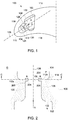
- FIG. 1 illustrates a cross-sectional view of a turbine assembly 100 in accordance with one embodiment.
- the turbine assembly 100 may be a turbine blade used in a turbine.
- the turbine assembly 100 extends between a first surface 116 and an opposite second surface 118.
- the first surface and second surface 116, 118 may be curved about a common axis in order to facilitate the movement of air flowing through the turbine.
- the turbine assembly 100 has a leading edge 110 that interconnects the first and second surfaces 116, 118.
- the leading edge 110 of the turbine assembly 100 is positioned distal to a rotating shaft of the turbine.
- the turbine assembly 100 is a unitary structure with integrated passages that enable the movement of cooling air through the turbine assembly.
- cavities, passages, chambers, or the like may be integrally fabricated with the airfoil.
- the turbine blade may incorporate a baffle design.
- a separate baffle component having a similar contour shape as the airfoil may be inserted into the airfoil such that cooling air flows through the baffle within the airfoil.
- the turbine assembly 100 includes a first interior cooling cavity 102 and a second interior cooling cavity 104.
- the first and second cooling cavities102, 104 are disposed within the interior of the turbine assembly 100.
- the first and second cooling cavities102, 104 are entirely contained within the turbine assembly 100 between the first and second surfaces 116, 118.
- the size of the first cooling cavity102 is larger than the size of the second cooling cavity104.
- the first and second cooling cavities 102, 104 may be of uniform shape and size.
- the size of the second cooling cavity 104 may be larger than the size of the first cooling cavity 102.
- the second cooling cavity 104 is disposed proximate to the leading edge 110 relative to the first cooling cavity 102.
- the second cooling cavity 104 is located closer to the leading edge 110 and distal the rotating shaft of the turbine assembly than the first cooling cavity 102.
- the first cooling cavity 102 is fluidly coupled with the second cooling cavity 104 by a forward facing step nozzle 106.
- the forward facing step nozzle 106 forms a channel 108 that interconnects the first and second cooling cavities 102, 104.
- the channel 108 is a passage that extends along a longitudinal axis 126 between the first and second cooling cavities 102, 104.
- the channel 108 has a first surface 128 and an opposite second surface 130 that are generally parallel or curved to the longitudinal axis 126.
- the channel has a front end 122 that is open to the first cooling cavity 102.
- the channel has a back end 124 that is open to the second cooling cavity 104.
- the channel 108 interconnects the first and second cooling cavities 102, 104.
- the first cooling cavity 102 directs cooling air within the turbine assembly 100 to the second cooling cavity 104.
- the cooling air travels in the direction A from the first cooling cavity 102 through the forward facing step nozzle 106 to the second cooling cavity 104.
- the cooling air flows in a direction towards the leading edge 110 of the turbine assembly 100 in order to cool the leading edge 110 when the turbine is operating.
- Figure 2 illustrates a cross-sectional view of the first and second cooling cavities 102, 104 and the channel 108 in accordance with one embodiment.
- the forward facing step nozzle 106 has steps 112 at an intersection 114 between the channel 108 and the second cooling cavity 104.
- the steps 112 are generally planar with the intersection 114 at the back end 124 of the channel 108.
- the steps 112 may be positioned at any other location within the channel between the first and second cooling cavities 102, 104.
- the steps 112 may be non-parallel, angled, or the like with respect to the intersection 114.
- the steps 112 extend into the channel 108 from the first and second surfaces 128, 130 of the channel in a direction towards the longitudinal axis 126.
- the forward facing step nozzle 106 has a first step 112a and a second step 112b.
- the first and second steps 112a, 112b have a uniform shape and size.
- the first step 112a may have a unique shape and/or size relative to the second step 112b.
- the steps 112 of the forward facing step nozzle 106 are integrally fabricated as a continuous structure with the channel 108.
- the steps 112 may be casted, machined, cut, molded, 3D printed, or the like to form an integrally fabricated structure with the channel 108.
- the steps 112 may be individual components that are joined to the channel 108 at the intersection 114 between the channel 108 and the second cooling cavity 104.
- the steps 112 may be welded, screwed, adhered, or the like to the channel 108 at the intersection 114.
- the steps 112 have elongated first sides 204 and narrow second sides 206.
- the elongated first sides 204 will be described and illustrated in more detail pertaining to Figures 3 and 4 .
- the narrow second sides 206 are generally perpendicular with the first and second surfaces 128, 130 of the channel 108.
- the narrow second sides 206 may be non-perpendicular, angled, or the like, with respect to the first and second surfaces 128, 130.
- the narrow second sides 206 are positioned facing towards the first cooling cavity 102.
- the narrow second sides 206 of the steps 112 protrude into the channel 108 towards the longitudinal axis 126 a distance B.
- the narrow second sides 206 extend into the channel 108 such that a cross-sectional area of the channel 108 at the steps 112 is smaller than a cross-sectional area of the channel 108 outside of the steps 112.
- the steps 112 of the forward facing step nozzle 106 produce a cross-sectional area of the channel 108 at the intersection 114 that is smaller than the cross-sectional area of the channel 108 away from the intersection 114.
- the cooling air flowing in the direction A transfers through a narrowing channel 108 from the first cooling cavity 102 to the second cooling cavity 104.
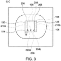
- Figure 3 illustrates a top view of the channel 108 opening into the second cooling cavity 104 in accordance with one embodiment.
- the forward facing step nozzle 106 has a parallelogram cross-sectional shape.
- the step nozzle 106 is a generally rectangular cross-sectional shape.
- the forward facing step nozzle 106 at the intersection 114 between the channel 108 and the second cooling cavity 104 has four sides.
- the step nozzle 106 has a first pair of opposing sides 208 and a second pair of opposing sides 210.
- the first pair of opposing sides 208 do not include the steps 112.
- the second pair of opposing sides 210 include the steps 112 of the step nozzle 106.
- the steps 112 extend into the channel 108 from the second pair of opposing sides 210.
- the elongated first sides 204 are generally parallel with the first and second surfaces 128, 130 of the channel 108.
- the elongated first side 204 of the first step 112a is positioned facing towards the elongated first side 204 of the second step 112b.
- the elongated first sides 204 may be non-parallel with the first and second surfaces 128, 130.
- the elongated first sides 204 may be rounded or angled to a radial degree that is different than an angled radial degree of the first and second surfaces
- the elongated first sides 204 protrude into the channel 108.
- the elongated first sides 204 protrude into the channel 108 a distance corresponding to the distance B of the narrow second sides 206.
- the elongated first sides 204 of the steps 112 extend a distance E between the first pair of opposing sides 208.
- the elongated first sides 204 extend between the first pair of opposing sides 208 along the length of the second pair of opposing sides 210.
- the elongated first sides 204 may extend a distance that is shorter than distance E.
- the elongated first sides 204 may extend a partial distance between the first pair of opposing sides 208.
- a first and second elongated first sides 204a, 204b extends a uniform distance E.
- the first and second elongated first sides 204a, 204b extend a uniform distance along a first and second opposing second sides 210a, 210b, respectively, between the first pair of opposing sides 208.
- the first elongated first side 204a may extend a distance shorter or longer than the second elongated first side 204b.
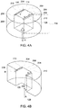
- Figure 4A illustrates a perspective view of the forward facing step nozzle 106 and the channel 108 in accordance with one embodiment.
- Figure 4B illustrates a cross-sectional perspective view of Figure 4A .
- the forward facing step nozzle 106 has a parallelogram cross-sectional shape. Cooling air transfers in the direction A from the first cooling cavity 102 through the channel 108 to the second cooling cavity 104.
- the steps 112 of the forward facing step nozzle 106 are positioned at the intersection 114 between the channel 108 and the second cooling cavity 104.
- the narrow second sides 206 of the steps 112 protrude into the channel a distance B (of Figures 2 and 3 ) away from first and second surfaces 128, 130 of the channel 108.
- the steps 112 protrude into the channel 108 such that the cross-sectional area of the channel 108 at the steps 112 is smaller than the cross-sectional area of the channel 108 outside of the steps.
- the cross-sectional area of the channel 108 at the steps 112 may be 10% smaller than the cross-sectional area of the channel 108 outside of the steps 112.
- the cross-sectional area at the steps may be less than or greater than 10% smaller than the cross-sectional area of the channel 108 outside of the steps.
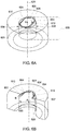
- Figure 5A illustrates a perspective view of a forward facing step nozzle 506 and a channel 508 in accordance with one embodiment.
- Figure 5B illustrates a cross-sectional perspective view of Figure 5A .
- the forward facing step nozzle 506 (corresponding to the forward facing step nozzle 106) has a closed curve cross-sectional shape.
- the forward facing step nozzle 506 is generally circular in shape.
- the forward facing step nozzle 506 may have an oval cross-sectional shape or the like. Cooling air transfers in the direction A from a first cooling cavity (e.g., first cooling cavity 102 of Figure 1 ) through the channel 508 to a second cooling cavity (e.g., the second cooling cavity 104 of Figure 1 ).
- a first cooling cavity e.g., first cooling cavity 102 of Figure 1
- a second cooling cavity e.g., the second cooling cavity 104 of Figure 1 .
- the forward facing step nozzle 506 has steps 512 at an intersection 514 between the channel 508 and a second cooling cavity.
- the steps 512 of the forward facing step nozzle 506 are integrally fabricated as a continuous structure with the channel 508.
- the steps 512 have elongated first sides 504 and narrow second sides 507 (corresponding to the elongated first sides 204 and narrow second sides 206 of Figures 4A and 4B ).
- the elongated first sides 504 are generally parallel with first and second surface 528, 530 of the channel 508, and the narrow second sides 507 are generally perpendicular with the first and second surfaces 528, 530 of the channel 508.
- the narrow second sides 507 of the steps 512 protrude into the channel 508 towards a longitudinal axis 526 a distance B.
- the narrow second sides 507 extend into the channel 508 such that a cross-sectional area of the channel 508 at the steps 512 is smaller than a cross-sectional area of the channel 508 outside of the steps 512.
- the cooling air flowing in the direction A transfers through a narrowing channel 508 from a first cooling cavity to a second cooling cavity.
- the step nozzle 506 has a first pair of opposing sides 509 and a second pair of opposing sides 510.
- the first pair of opposing sides 509 of the closed curved cross-sectional shape do not include the steps 512.
- the second pair of opposing sides 510 of the closed curved cross-sectional shape includes the steps 512 of the step nozzle 506.
- the steps 512 extend into the channel 508 from the second pair of opposing sides 510.
- the first pair of opposing sides 509 have an arc length generally uniform to an arc length of the second pair of opposing sides 510.
- the first and second pair of opposing sides 509, 510 are generally extend a similar percentage of length of the entire closed curved cross-sectional shape of the step nozzle 506.
- the first pair of opposing sides 509 may have an arc length smaller or larger than the arc length of the second pair of opposing sides 510.
- Figure 6A illustrates a perspective view of a forward facing step nozzle 606 and a channel 608 in accordance with one embodiment.
- Figure 6B illustrates a cross-sectional perspective view of Figure 6A .
- the forward facing step nozzle 606 (corresponding to the forward facing step nozzle 106) has a closed curve cross-sectional shape.
- the forward facing step nozzle 606 has generally an elliptical cross-sectional shape. Cooling air transfers in the direction A from a first cooling cavity (e.g., first cooling cavity 102 of Figure 1 ) through the channel 608 to a second cooling cavity (e.g., the second cooling cavity 104 of Figure 1 ).
- the forward facing step nozzle 606 has steps 612 at an intersection 614 between the channel 608 and a second cooling cavity.
- the steps 612 of the forward facing step nozzle 606 are integrally fabricated as a continuous structure with the channel 608.
- the steps 612 have elongated first sides 604 and narrow second sides 607 (corresponding to the elongated first sides 204 and narrow second sides 206 of Figures 4A and 4B ).
- the elongated first sides 504 are generally non-parallel with first and second surface 628, 630 of the channel 608.
- the elongated first sides 604 are generally curved about a longitudinal axis 626 to a radial degree in a generally oval cross-sectional shape.
- the generally oval cross-sectional shape is different than an angled radial degree of the generally round cross-sectional shape of the first and second surfaces 628, 630.
- the narrow second sides 607 are generally perpendicular with the first and second surfaces 628, 630 of the channel 608.
- the narrow second sides 607 of the steps 612 protrude into the channel 608 towards the longitudinal axis 626 a distance B.
- the narrow second sides 607 extend into the channel 608 such that a cross-sectional area of the channel 608 at the steps 612 is smaller than a cross-sectional area of the channel 608 outside of the steps 612.
- the cooling air flowing in the direction A transfers through a narrowing channel 608 from a first cooling cavity to a second cooling cavity.
- the step nozzle 606 has a first pair of opposing sides 609 and a second pair of opposing sides 610.
- the first pair of opposing sides 609 of the closed curved cross-sectional shape do not include the steps 612.
- the second pair of opposing sides 610 of the closed curved cross-sectional shape includes the steps 612 of the step nozzle 606.
- the steps 612 extend into the channel 608 from the second pair of opposing sides 610.
- the first pair of opposing sides 609 have an arc length generally uniform to an arc length of the second pair of opposing sides 610.
- the first and second pair of opposing sides 609, 610 are generally extend a similar percentage of length of the entire closed curved cross-sectional shape of the step nozzle 606.
- the first pair of opposing sides 609 may have an arc length smaller or larger than the arc length of the second pair of opposing sides 610.
- Figure 7A is a graph illustrating a heat transfer coefficient (HTC) map corresponding to a channel that is devoid a forward facing step nozzle.
- Figure 7B is a graph illustrating a heat transfer coefficient map corresponding to a channel having a forward facing step nozzle.
- Figure 7B illustrates a HTC map corresponding to channel 108 having the forward facing step nozzle 106 at the intersection 114 between the channel 108 and the second cooling cavity 104.
- Figure 7C is a chart illustrating HTC measurements versus mass flow rate for a channel devoid a step nozzle and a channel having a step nozzle (e.g., step nozzle 106).
- Figures 7A, 7B and 7C will be discussed in detail together.
- the channel 108 having the forward facing step nozzle 106 has a heat transfer coefficient (HTC) that is greater than the HTC for a baseline channel devoid a step nozzle.
- HTC heat transfer coefficient
- a point 702a charts the HTC for the forward facing step nozzle 106
- a point 702b charts the HTC for the baseline channel devoid a step nozzle.
- the points 702a, 702b are measured at the same pressure drop of the cooling air flowing through the turbine assembly.
- point 702a has a HTC that is greater than a HTC at point 702b.
- a point 704a for the forward facing step nozzle 106 has a HTC that is greater than a HTC at point 704b for the baseline channel devoid a step nozzle.
- the forward facing step nozzle 106 has an improved heat transfer than a channel devoid a step nozzle.
- FIG 8 illustrates a cross-sectional partial view of a combustion chamber 800 in accordance with one embodiment.
- the combustion chamber 800 comprises a first cooling cavity 802 and a second cooling cavity 804.
- the first and second cooling cavities 802, 804 are disposed within the interior of the combustion chamber 800.
- the second cooling cavity 804 is disposed proximate a combustor wall 810 (corresponding to the leading edge 110 of Figure 1 ) relative to the first cooling cavity 802.
- the second cooling cavity 804 is disposed distal the hot gas that transfers through the combustion chamber relative to the first cooling cavity 802.
- the first cooling cavity 802 is fluidly coupled with the second cooling cavity 804 by a forward facing step nozzle 806 (corresponding to the step nozzle 106 of Figure 1 ).
- the forward facing step nozzle 806 forms a channel 808 that interconnects the first and second cooling cavities 802, 804.
- the channel has a first surface 828 and a second surface 830 opposite the first surface 828.
- the channel has a front end 822 that is open to the first cooling cavity 802 and a back end 824 that is open to the second cooling cavity 804.
- the forward facing step nozzle 806 has steps 812 (corresponding to the steps 112 of Figures 1 and 2 ) at an intersection 814 between the channel 808 and the second cooling cavity 804.
- the steps 812 are generally planar with the intersection 814 at the back end 824 of the channel 808.
- the steps 812 may be non-planar, perpendicular, angled, or the like with respect to the intersection 814.
- the steps extend into the channel 808 from the first and second surfaces 828, 830 in a direction towards a longitudinal axis 826.
- the steps 812 extend into the channel 808 such that a cross-sectional area of the channel 808 at the steps 812 is smaller than a cross-sectional area of the channel 808 outside of the steps 812.
- the cooling air flowing in the direction F transfers through a narrowing channel 808 from the first cooling cavity 802 to the second cooling cavity 804.
- the first cooling cavity 802 directs cooling air within the combustion chamber 800 to the second cooling cavity 804.
- the cooling air travels in a direction F from the first cooling cavity 802, through the channel 808 and the forward facing step nozzle 806, to the second cooling cavity 804.
- the cooling air flows in a direction towards the combustor wall 810 of the combustion chamber 800 in order to cool the combustion chamber when the gas turbine is operating.
- Figure 9 illustrates one embodiment of a method of operation of cooling the turbine assembly 100 or a combustion chamber 800.
- a second cooling cavity e.g., second cooling cavity 104
- a first cooling cavity e.g., first cooling cavity 102
- a channel e.g., the channel 108.
- the first and second cooling cavities and channel are positioned internally within one or more of a turbine assembly or a combustion chamber.
- a forward facing step nozzle is positioned at an intersection between the channel and the second cooling cavity.
- the forward facing step nozzle includes steps having elongated first sides and narrow second sides.
- the elongated first sides of the steps protrude into the channel a distance corresponding to the length of narrow second sides.
- the elongated first sides of the steps protrude into the channel such that a cross-sectional area of the channel at the steps is smaller than a cross-sectional area of the channel outside of the steps.
- the forward facing step nozzle has a first pair of opposing sides and a second pair of opposing sides.
- the first pair of opposing sides do not include steps.
- the second pair of opposing sides include the steps.
- cooling air is directed from the first cooling cavity, through the channel and the forward facing step nozzle, into the second cooling cavity.
- an assembly comprises a first cooling cavity disposed within one or more of a turbine assembly or a combustion chamber of an engine.
- the first cooling cavity directs cooling air within the one or more of the turbine assembly or the combustion chamber.
- the assembly comprises a second cooling cavity also disposed within the one or more of the turbine assembly or the combustion chamber.
- the second cooling cavity receives at least some of the cooling air from the first cooling cavity.
- a forward facing step nozzle forms a channel that fluidly couples the first cooling cavity with the second cooling cavity.
- the step nozzle includes steps having elongated first sides and narrow second sides. The elongated first sides or the steps protrude into the channel such that a cross-sectional area of the channel of the step nozzle at the steps is smaller than a cross-sectional area of the channel of the step nozzle outside of the steps.
- the steps of the step nozzle are disposed on opposing sides of the channel of the step nozzle.
- the step nozzle has a cross-sectional shape with the opposing sides that include the steps and additional opposing sides that do not include steps.
- the step nozzle has a parallelogram cross-sectional shape having four sides with the steps of the step nozzle disposed on opposing sides of the parallelogram cross-sectional shape.
- the step nozzle has a closed curve cross-sectional shape with the steps of the step nozzle disposed on opposing sides of the closed curve cross-sectional shape.
- the steps of the step nozzle are disposed at an intersection between the channel of the step nozzle and the second cavity.
- the first and second cooling cavities are disposed inside the turbine assembly with the second cooling cavity disposed closer to a leading edge of the turbine assembly than the first cooling cavity.
- the steps of the forward facing step nozzle are integrally fabricated as a continuous structure.
- an assembly comprises a first cooling cavity disposed within one or more of a turbine assembly or a combustion chamber of an engine.
- the first cooling cavity directs cooling air within the one or more of the turbine assembly or the combustion chamber.
- the assembly comprises a second cooling cavity also disposed within the one or more of the turbine assembly or the combustion chamber.
- the second cooling cavity receives at least some of the cooling air from the first cooling cavity.
- a forward facing step nozzle forms a channel that fluidly couples the first cooling cavity with the second cooling cavity.
- the step nozzle includes steps having elongated first sides and narrow second sides. The elongated first sides of the steps are disposed on opposing sides of the channel.
- the elongated first sides of the steps protrude into the channel such that a cross-sectional area of the channel of the step nozzle at the steps is smaller than a cross-sectional area of the channel of the step nozzle outside of the steps.
- the step nozzle has a cross-sectional shape with the opposing sides that include the steps and additional opposing sides that do not include the steps.
- the step nozzle has a parallelogram cross-sectional shape having four sides with the steps of the step nozzle disposed on opposing sides of the parallelogram cross-sectional shape.
- the step nozzle has a closed curve cross-sectional shape with the steps of the step nozzle disposed on opposing sides of the closed curve cross-sectional shape.
- the steps of the nozzle are disposed at an intersection between the channel of the step nozzle and the second cavity.
- the first and second cooling cavities are disposed inside the turbine assembly with the second cooling cavity disposed closer to a leading edge of the turbine assembly than the first cooling cavity.
- the steps and the forward facing step nozzle are integrally fabricated as a continuous structure.
- a method for cooling one or more of a turbine assembly or a combustion chamber of an engine comprises fluidly coupling a first cooling cavity and a second cooling cavity with a channel.
- the first cooling cavity directs cooling air within one or more of the turbine assembly or the combustion chamber.
- the second cooling cavity receives at least some of the cooling air from the first cooling cavity.
- the method comprises positioning a forward facing step nozzle at an intersection between the channel and the second cooling cavity.
- the step nozzle includes steps having elongated first sides and narrow second sides. The elongated first sides of the steps protrude into the channel such that a cross-sectional area of the channel of the step nozzle at the steps is smaller than a cross-sectional area of the channel of the step nozzle outside of the steps.
- the method also includes disposing the steps of the step nozzle on opposing sides of the channel of the step nozzle.
- the method also includes integrally fabricating the steps and the forward facing step nozzle as a continuous structure.
- the method also includes disposing the first and second cooling cavities inside of the turbine assembly with the second cooling cavity disposed closer to a leading edge of the turbine assembly than the first cooling cavity.
Landscapes
- Engineering & Computer Science (AREA)
- Mechanical Engineering (AREA)
- General Engineering & Computer Science (AREA)
- Chemical & Material Sciences (AREA)
- Combustion & Propulsion (AREA)
- Turbine Rotor Nozzle Sealing (AREA)
Applications Claiming Priority (1)
| Application Number | Priority Date | Filing Date | Title |
|---|---|---|---|
| US15/352,773 US10738700B2 (en) | 2016-11-16 | 2016-11-16 | Turbine assembly |
Publications (2)
| Publication Number | Publication Date |
|---|---|
| EP3323978A1 true EP3323978A1 (fr) | 2018-05-23 |
| EP3323978B1 EP3323978B1 (fr) | 2019-05-22 |
Family
ID=60262772
Family Applications (1)
| Application Number | Title | Priority Date | Filing Date |
|---|---|---|---|
| EP17199889.1A Active EP3323978B1 (fr) | 2016-11-16 | 2017-11-03 | Ensemble de turbine |
Country Status (3)
| Country | Link |
|---|---|
| US (1) | US10738700B2 (fr) |
| EP (1) | EP3323978B1 (fr) |
| CN (1) | CN208040455U (fr) |
Families Citing this family (1)
| Publication number | Priority date | Publication date | Assignee | Title |
|---|---|---|---|---|
| US11391161B2 (en) * | 2018-07-19 | 2022-07-19 | General Electric Company | Component for a turbine engine with a cooling hole |
Citations (6)
| Publication number | Priority date | Publication date | Assignee | Title |
|---|---|---|---|---|
| US4073599A (en) * | 1976-08-26 | 1978-02-14 | Westinghouse Electric Corporation | Hollow turbine blade tip closure |
| US5752801A (en) * | 1997-02-20 | 1998-05-19 | Westinghouse Electric Corporation | Apparatus for cooling a gas turbine airfoil and method of making same |
| US20050053458A1 (en) * | 2003-09-04 | 2005-03-10 | Siemens Westinghouse Power Corporation | Cooling system for a turbine blade |
| US20080286115A1 (en) * | 2007-05-18 | 2008-11-20 | Siemens Power Generation, Inc. | Blade for a gas turbine engine |
| EP2584145A1 (fr) * | 2011-10-20 | 2013-04-24 | Siemens Aktiengesellschaft | Pale ou aube de guidage de turbine refroidie pour turbomachine |
| US20130209235A1 (en) * | 2012-02-15 | 2013-08-15 | United Technologies Corporation | Gas turbine engine component with cusped, lobed cooling hole |
Family Cites Families (24)
| Publication number | Priority date | Publication date | Assignee | Title |
|---|---|---|---|---|
| US3844343A (en) * | 1973-02-02 | 1974-10-29 | Gen Electric | Impingement-convective cooling system |
| GB2343486B (en) * | 1998-06-19 | 2000-09-20 | Rolls Royce Plc | Improvemnts in or relating to cooling systems for gas turbine engine airfoil |
| US6579061B1 (en) | 2001-07-27 | 2003-06-17 | General Electric Company | Selective step turbine nozzle |
| GB2402715B (en) | 2003-06-10 | 2006-06-14 | Rolls Royce Plc | Gas turbine aerofoil |
| US7690892B1 (en) | 2006-11-16 | 2010-04-06 | Florida Turbine Technologies, Inc. | Turbine airfoil with multiple impingement cooling circuit |
| ES2442873T3 (es) | 2008-03-31 | 2014-02-14 | Alstom Technology Ltd | Perfil aerodinámico de turbina de gas |
| US8079813B2 (en) | 2009-01-19 | 2011-12-20 | Siemens Energy, Inc. | Turbine blade with multiple trailing edge cooling slots |
| US8613597B1 (en) | 2011-01-17 | 2013-12-24 | Florida Turbine Technologies, Inc. | Turbine blade with trailing edge cooling |
| US8777569B1 (en) | 2011-03-16 | 2014-07-15 | Florida Turbine Technologies, Inc. | Turbine vane with impingement cooling insert |
| JP2012202335A (ja) | 2011-03-25 | 2012-10-22 | Mitsubishi Heavy Ind Ltd | インピンジメント冷却構造、及び、それを用いたガスタービン静翼 |
| CN202023597U (zh) | 2011-04-21 | 2011-11-02 | 西北工业大学 | 一种带冠的燃气涡轮冷却叶片 |
| US8826668B2 (en) | 2011-08-02 | 2014-09-09 | Siemens Energy, Inc. | Two stage serial impingement cooling for isogrid structures |
| JP2013100765A (ja) | 2011-11-08 | 2013-05-23 | Ihi Corp | インピンジ冷却機構、タービン翼及び燃焼器 |
| US8734108B1 (en) | 2011-11-22 | 2014-05-27 | Florida Turbine Technologies, Inc. | Turbine blade with impingement cooling cavities and platform cooling channels connected in series |
| JP5834876B2 (ja) | 2011-12-15 | 2015-12-24 | 株式会社Ihi | インピンジ冷却機構、タービン翼及び燃焼器 |
| US9296039B2 (en) * | 2012-04-24 | 2016-03-29 | United Technologies Corporation | Gas turbine engine airfoil impingement cooling |
| US20130318986A1 (en) | 2012-06-05 | 2013-12-05 | General Electric Company | Impingement cooled combustor |
| US10107107B2 (en) | 2012-06-28 | 2018-10-23 | United Technologies Corporation | Gas turbine engine component with discharge slot having oval geometry |
| US9376920B2 (en) | 2012-09-28 | 2016-06-28 | United Technologies Corporation | Gas turbine engine cooling hole with circular exit geometry |
| US10145246B2 (en) * | 2014-09-04 | 2018-12-04 | United Technologies Corporation | Staggered crossovers for airfoils |
| EP3000970B1 (fr) | 2014-09-26 | 2019-06-12 | Ansaldo Energia Switzerland AG | Système de refroidissement pour le bord d'attaque d'une aube de turbine d'une turbine à gaz |
| US9849510B2 (en) | 2015-04-16 | 2017-12-26 | General Electric Company | Article and method of forming an article |
| US9976441B2 (en) | 2015-05-29 | 2018-05-22 | General Electric Company | Article, component, and method of forming an article |
| US9995151B2 (en) | 2015-08-17 | 2018-06-12 | General Electric Company | Article and manifold for thermal adjustment of a turbine component |
-
2016
- 2016-11-16 US US15/352,773 patent/US10738700B2/en active Active
-
2017
- 2017-11-03 EP EP17199889.1A patent/EP3323978B1/fr active Active
- 2017-11-16 CN CN201721536860.2U patent/CN208040455U/zh active Active
Patent Citations (6)
| Publication number | Priority date | Publication date | Assignee | Title |
|---|---|---|---|---|
| US4073599A (en) * | 1976-08-26 | 1978-02-14 | Westinghouse Electric Corporation | Hollow turbine blade tip closure |
| US5752801A (en) * | 1997-02-20 | 1998-05-19 | Westinghouse Electric Corporation | Apparatus for cooling a gas turbine airfoil and method of making same |
| US20050053458A1 (en) * | 2003-09-04 | 2005-03-10 | Siemens Westinghouse Power Corporation | Cooling system for a turbine blade |
| US20080286115A1 (en) * | 2007-05-18 | 2008-11-20 | Siemens Power Generation, Inc. | Blade for a gas turbine engine |
| EP2584145A1 (fr) * | 2011-10-20 | 2013-04-24 | Siemens Aktiengesellschaft | Pale ou aube de guidage de turbine refroidie pour turbomachine |
| US20130209235A1 (en) * | 2012-02-15 | 2013-08-15 | United Technologies Corporation | Gas turbine engine component with cusped, lobed cooling hole |
Also Published As
| Publication number | Publication date |
|---|---|
| US10738700B2 (en) | 2020-08-11 |
| CN208040455U (zh) | 2018-11-02 |
| EP3323978B1 (fr) | 2019-05-22 |
| US20180135519A1 (en) | 2018-05-17 |
Similar Documents
| Publication | Publication Date | Title |
|---|---|---|
| US8628292B2 (en) | Eccentric chamfer at inlet of branches in a flow channel | |
| KR101552450B1 (ko) | 가스 터빈 동익 및 가스 터빈 | |
| CN104564350B (zh) | 用于冷却燃气涡轮的热气体路径中的构件的布置 | |
| US20180135423A1 (en) | Double impingement slot cap assembly | |
| US8079810B2 (en) | Turbine airfoil cooling system with divergent film cooling hole | |
| EP2325440B1 (fr) | Aube avec microcircuits de refroidissement en forme de serpentin | |
| JP7175599B2 (ja) | 後縁冷却回路を備えたターボ機械ブレード | |
| JP2011183922A (ja) | 航空機における翼前縁部の防除氷装置及び航空機主翼 | |
| EP1870561A3 (fr) | Refroidissement du bord d'attaque d'un composant de turbine à gaz par générateurs de turbulence | |
| US20170356295A1 (en) | Turbine component cooling holes | |
| EP3436669B1 (fr) | Profil aérodynamique de turbine avec canaux de refroidissement internes ayant un élément de diviseur d'écoulement | |
| US9822653B2 (en) | Cooling structure for stationary blade | |
| US20180171872A1 (en) | Cooling assembly for a turbine assembly | |
| EP2103781A2 (fr) | Microcircuit de refroidissement de bord arrière avec des sorties alternées convergentes | |
| JP2018087571A (ja) | 正圧側インピンジメントを有する部分的にラップされた後縁冷却回路 | |
| EP3184738A1 (fr) | Circuit de refroidissement pour aube à parois multiples | |
| US10619487B2 (en) | Cooling assembly for a turbine assembly | |
| EP2706195A1 (fr) | Noyau de refroidissement par impact pour une aube de turbine à gaz avec cloison de séparation | |
| EP3323978B1 (fr) | Ensemble de turbine | |
| EP3438412A1 (fr) | Composant de moteur comportant des broches de chevron non uniformes | |
| EP3828383A1 (fr) | Profil d'aube avec circuit de refroidissement de bord de fuite | |
| CN106321155B (zh) | 燃气涡轮叶片 | |
| US11230930B2 (en) | Cooling assembly for a turbine assembly | |
| US10612396B2 (en) | Mechanical component |
Legal Events
| Date | Code | Title | Description |
|---|---|---|---|
| PUAI | Public reference made under article 153(3) epc to a published international application that has entered the european phase |
Free format text: ORIGINAL CODE: 0009012 |
|
| STAA | Information on the status of an ep patent application or granted ep patent |
Free format text: STATUS: THE APPLICATION HAS BEEN PUBLISHED |
|
| AK | Designated contracting states |
Kind code of ref document: A1 Designated state(s): AL AT BE BG CH CY CZ DE DK EE ES FI FR GB GR HR HU IE IS IT LI LT LU LV MC MK MT NL NO PL PT RO RS SE SI SK SM TR |
|
| AX | Request for extension of the european patent |
Extension state: BA ME |
|
| STAA | Information on the status of an ep patent application or granted ep patent |
Free format text: STATUS: REQUEST FOR EXAMINATION WAS MADE |
|
| 17P | Request for examination filed |
Effective date: 20181123 |
|
| RBV | Designated contracting states (corrected) |
Designated state(s): AL AT BE BG CH CY CZ DE DK EE ES FI FR GB GR HR HU IE IS IT LI LT LU LV MC MK MT NL NO PL PT RO RS SE SI SK SM TR |
|
| GRAP | Despatch of communication of intention to grant a patent |
Free format text: ORIGINAL CODE: EPIDOSNIGR1 |
|
| STAA | Information on the status of an ep patent application or granted ep patent |
Free format text: STATUS: GRANT OF PATENT IS INTENDED |
|
| INTG | Intention to grant announced |
Effective date: 20190111 |
|
| GRAS | Grant fee paid |
Free format text: ORIGINAL CODE: EPIDOSNIGR3 |
|
| GRAA | (expected) grant |
Free format text: ORIGINAL CODE: 0009210 |
|
| STAA | Information on the status of an ep patent application or granted ep patent |
Free format text: STATUS: THE PATENT HAS BEEN GRANTED |
|
| AK | Designated contracting states |
Kind code of ref document: B1 Designated state(s): AL AT BE BG CH CY CZ DE DK EE ES FI FR GB GR HR HU IE IS IT LI LT LU LV MC MK MT NL NO PL PT RO RS SE SI SK SM TR |
|
| REG | Reference to a national code |
Ref country code: GB Ref legal event code: FG4D |
|
| REG | Reference to a national code |
Ref country code: CH Ref legal event code: EP |
|
| REG | Reference to a national code |
Ref country code: IE Ref legal event code: FG4D |
|
| REG | Reference to a national code |
Ref country code: DE Ref legal event code: R096 Ref document number: 602017004128 Country of ref document: DE |
|
| REG | Reference to a national code |
Ref country code: AT Ref legal event code: REF Ref document number: 1136339 Country of ref document: AT Kind code of ref document: T Effective date: 20190615 |
|
| REG | Reference to a national code |
Ref country code: NL Ref legal event code: MP Effective date: 20190522 |
|
| REG | Reference to a national code |
Ref country code: LT Ref legal event code: MG4D |
|
| PG25 | Lapsed in a contracting state [announced via postgrant information from national office to epo] |
Ref country code: ES Free format text: LAPSE BECAUSE OF FAILURE TO SUBMIT A TRANSLATION OF THE DESCRIPTION OR TO PAY THE FEE WITHIN THE PRESCRIBED TIME-LIMIT Effective date: 20190522 Ref country code: LT Free format text: LAPSE BECAUSE OF FAILURE TO SUBMIT A TRANSLATION OF THE DESCRIPTION OR TO PAY THE FEE WITHIN THE PRESCRIBED TIME-LIMIT Effective date: 20190522 Ref country code: NL Free format text: LAPSE BECAUSE OF FAILURE TO SUBMIT A TRANSLATION OF THE DESCRIPTION OR TO PAY THE FEE WITHIN THE PRESCRIBED TIME-LIMIT Effective date: 20190522 Ref country code: HR Free format text: LAPSE BECAUSE OF FAILURE TO SUBMIT A TRANSLATION OF THE DESCRIPTION OR TO PAY THE FEE WITHIN THE PRESCRIBED TIME-LIMIT Effective date: 20190522 Ref country code: NO Free format text: LAPSE BECAUSE OF FAILURE TO SUBMIT A TRANSLATION OF THE DESCRIPTION OR TO PAY THE FEE WITHIN THE PRESCRIBED TIME-LIMIT Effective date: 20190822 Ref country code: FI Free format text: LAPSE BECAUSE OF FAILURE TO SUBMIT A TRANSLATION OF THE DESCRIPTION OR TO PAY THE FEE WITHIN THE PRESCRIBED TIME-LIMIT Effective date: 20190522 Ref country code: PT Free format text: LAPSE BECAUSE OF FAILURE TO SUBMIT A TRANSLATION OF THE DESCRIPTION OR TO PAY THE FEE WITHIN THE PRESCRIBED TIME-LIMIT Effective date: 20190922 Ref country code: SE Free format text: LAPSE BECAUSE OF FAILURE TO SUBMIT A TRANSLATION OF THE DESCRIPTION OR TO PAY THE FEE WITHIN THE PRESCRIBED TIME-LIMIT Effective date: 20190522 Ref country code: AL Free format text: LAPSE BECAUSE OF FAILURE TO SUBMIT A TRANSLATION OF THE DESCRIPTION OR TO PAY THE FEE WITHIN THE PRESCRIBED TIME-LIMIT Effective date: 20190522 |
|
| PG25 | Lapsed in a contracting state [announced via postgrant information from national office to epo] |
Ref country code: LV Free format text: LAPSE BECAUSE OF FAILURE TO SUBMIT A TRANSLATION OF THE DESCRIPTION OR TO PAY THE FEE WITHIN THE PRESCRIBED TIME-LIMIT Effective date: 20190522 Ref country code: GR Free format text: LAPSE BECAUSE OF FAILURE TO SUBMIT A TRANSLATION OF THE DESCRIPTION OR TO PAY THE FEE WITHIN THE PRESCRIBED TIME-LIMIT Effective date: 20190823 Ref country code: BG Free format text: LAPSE BECAUSE OF FAILURE TO SUBMIT A TRANSLATION OF THE DESCRIPTION OR TO PAY THE FEE WITHIN THE PRESCRIBED TIME-LIMIT Effective date: 20190822 Ref country code: RS Free format text: LAPSE BECAUSE OF FAILURE TO SUBMIT A TRANSLATION OF THE DESCRIPTION OR TO PAY THE FEE WITHIN THE PRESCRIBED TIME-LIMIT Effective date: 20190522 |
|
| REG | Reference to a national code |
Ref country code: AT Ref legal event code: MK05 Ref document number: 1136339 Country of ref document: AT Kind code of ref document: T Effective date: 20190522 |
|
| PG25 | Lapsed in a contracting state [announced via postgrant information from national office to epo] |
Ref country code: CZ Free format text: LAPSE BECAUSE OF FAILURE TO SUBMIT A TRANSLATION OF THE DESCRIPTION OR TO PAY THE FEE WITHIN THE PRESCRIBED TIME-LIMIT Effective date: 20190522 Ref country code: RO Free format text: LAPSE BECAUSE OF FAILURE TO SUBMIT A TRANSLATION OF THE DESCRIPTION OR TO PAY THE FEE WITHIN THE PRESCRIBED TIME-LIMIT Effective date: 20190522 Ref country code: SK Free format text: LAPSE BECAUSE OF FAILURE TO SUBMIT A TRANSLATION OF THE DESCRIPTION OR TO PAY THE FEE WITHIN THE PRESCRIBED TIME-LIMIT Effective date: 20190522 Ref country code: EE Free format text: LAPSE BECAUSE OF FAILURE TO SUBMIT A TRANSLATION OF THE DESCRIPTION OR TO PAY THE FEE WITHIN THE PRESCRIBED TIME-LIMIT Effective date: 20190522 Ref country code: AT Free format text: LAPSE BECAUSE OF FAILURE TO SUBMIT A TRANSLATION OF THE DESCRIPTION OR TO PAY THE FEE WITHIN THE PRESCRIBED TIME-LIMIT Effective date: 20190522 Ref country code: DK Free format text: LAPSE BECAUSE OF FAILURE TO SUBMIT A TRANSLATION OF THE DESCRIPTION OR TO PAY THE FEE WITHIN THE PRESCRIBED TIME-LIMIT Effective date: 20190522 |
|
| REG | Reference to a national code |
Ref country code: DE Ref legal event code: R097 Ref document number: 602017004128 Country of ref document: DE |
|
| PG25 | Lapsed in a contracting state [announced via postgrant information from national office to epo] |
Ref country code: SM Free format text: LAPSE BECAUSE OF FAILURE TO SUBMIT A TRANSLATION OF THE DESCRIPTION OR TO PAY THE FEE WITHIN THE PRESCRIBED TIME-LIMIT Effective date: 20190522 |
|
| PLBE | No opposition filed within time limit |
Free format text: ORIGINAL CODE: 0009261 |
|
| STAA | Information on the status of an ep patent application or granted ep patent |
Free format text: STATUS: NO OPPOSITION FILED WITHIN TIME LIMIT |
|
| PG25 | Lapsed in a contracting state [announced via postgrant information from national office to epo] |
Ref country code: TR Free format text: LAPSE BECAUSE OF FAILURE TO SUBMIT A TRANSLATION OF THE DESCRIPTION OR TO PAY THE FEE WITHIN THE PRESCRIBED TIME-LIMIT Effective date: 20190522 |
|
| 26N | No opposition filed |
Effective date: 20200225 |
|
| PG25 | Lapsed in a contracting state [announced via postgrant information from national office to epo] |
Ref country code: PL Free format text: LAPSE BECAUSE OF FAILURE TO SUBMIT A TRANSLATION OF THE DESCRIPTION OR TO PAY THE FEE WITHIN THE PRESCRIBED TIME-LIMIT Effective date: 20190522 |
|
| PG25 | Lapsed in a contracting state [announced via postgrant information from national office to epo] |
Ref country code: SI Free format text: LAPSE BECAUSE OF FAILURE TO SUBMIT A TRANSLATION OF THE DESCRIPTION OR TO PAY THE FEE WITHIN THE PRESCRIBED TIME-LIMIT Effective date: 20190522 |
|
| PG25 | Lapsed in a contracting state [announced via postgrant information from national office to epo] |
Ref country code: LU Free format text: LAPSE BECAUSE OF NON-PAYMENT OF DUE FEES Effective date: 20191103 Ref country code: MC Free format text: LAPSE BECAUSE OF FAILURE TO SUBMIT A TRANSLATION OF THE DESCRIPTION OR TO PAY THE FEE WITHIN THE PRESCRIBED TIME-LIMIT Effective date: 20190522 |
|
| REG | Reference to a national code |
Ref country code: BE Ref legal event code: MM Effective date: 20191130 |
|
| PG25 | Lapsed in a contracting state [announced via postgrant information from national office to epo] |
Ref country code: FR Free format text: LAPSE BECAUSE OF NON-PAYMENT OF DUE FEES Effective date: 20191130 Ref country code: IE Free format text: LAPSE BECAUSE OF NON-PAYMENT OF DUE FEES Effective date: 20191103 |
|
| PG25 | Lapsed in a contracting state [announced via postgrant information from national office to epo] |
Ref country code: BE Free format text: LAPSE BECAUSE OF NON-PAYMENT OF DUE FEES Effective date: 20191130 |
|
| PG25 | Lapsed in a contracting state [announced via postgrant information from national office to epo] |
Ref country code: CY Free format text: LAPSE BECAUSE OF FAILURE TO SUBMIT A TRANSLATION OF THE DESCRIPTION OR TO PAY THE FEE WITHIN THE PRESCRIBED TIME-LIMIT Effective date: 20190522 |
|
| PG25 | Lapsed in a contracting state [announced via postgrant information from national office to epo] |
Ref country code: LI Free format text: LAPSE BECAUSE OF FAILURE TO SUBMIT A TRANSLATION OF THE DESCRIPTION OR TO PAY THE FEE WITHIN THE PRESCRIBED TIME-LIMIT Effective date: 20201130 Ref country code: IS Free format text: LAPSE BECAUSE OF FAILURE TO SUBMIT A TRANSLATION OF THE DESCRIPTION OR TO PAY THE FEE WITHIN THE PRESCRIBED TIME-LIMIT Effective date: 20190922 Ref country code: CH Free format text: LAPSE BECAUSE OF FAILURE TO SUBMIT A TRANSLATION OF THE DESCRIPTION OR TO PAY THE FEE WITHIN THE PRESCRIBED TIME-LIMIT Effective date: 20201130 |
|
| REG | Reference to a national code |
Ref country code: CH Ref legal event code: PL |
|
| PG25 | Lapsed in a contracting state [announced via postgrant information from national office to epo] |
Ref country code: HU Free format text: LAPSE BECAUSE OF FAILURE TO SUBMIT A TRANSLATION OF THE DESCRIPTION OR TO PAY THE FEE WITHIN THE PRESCRIBED TIME-LIMIT; INVALID AB INITIO Effective date: 20171103 Ref country code: MT Free format text: LAPSE BECAUSE OF FAILURE TO SUBMIT A TRANSLATION OF THE DESCRIPTION OR TO PAY THE FEE WITHIN THE PRESCRIBED TIME-LIMIT Effective date: 20190522 |
|
| PG25 | Lapsed in a contracting state [announced via postgrant information from national office to epo] |
Ref country code: MK Free format text: LAPSE BECAUSE OF FAILURE TO SUBMIT A TRANSLATION OF THE DESCRIPTION OR TO PAY THE FEE WITHIN THE PRESCRIBED TIME-LIMIT Effective date: 20190522 |
|
| GBPC | Gb: european patent ceased through non-payment of renewal fee |
Effective date: 20211103 |
|
| PG25 | Lapsed in a contracting state [announced via postgrant information from national office to epo] |
Ref country code: GB Free format text: LAPSE BECAUSE OF NON-PAYMENT OF DUE FEES Effective date: 20211103 |
|
| PGFP | Annual fee paid to national office [announced via postgrant information from national office to epo] |
Ref country code: IT Payment date: 20221020 Year of fee payment: 6 |
|
| REG | Reference to a national code |
Ref country code: DE Ref legal event code: R082 Ref document number: 602017004128 Country of ref document: DE Ref country code: DE Ref legal event code: R081 Ref document number: 602017004128 Country of ref document: DE Owner name: GENERAL ELECTRIC TECHNOLOGY GMBH, CH Free format text: FORMER OWNER: GENERAL ELECTRIC COMPANY, SCHENECTADY, NY, US |
|
| PGFP | Annual fee paid to national office [announced via postgrant information from national office to epo] |
Ref country code: DE Payment date: 20231019 Year of fee payment: 7 |