EP3323958B1 - Arrangement for attaching a panel to a groove by two opposing wedges - Google Patents
Arrangement for attaching a panel to a groove by two opposing wedges Download PDFInfo
- Publication number
- EP3323958B1 EP3323958B1 EP17192624.9A EP17192624A EP3323958B1 EP 3323958 B1 EP3323958 B1 EP 3323958B1 EP 17192624 A EP17192624 A EP 17192624A EP 3323958 B1 EP3323958 B1 EP 3323958B1
- Authority
- EP
- European Patent Office
- Prior art keywords
- panel
- groove
- wedge
- vertical
- screw
- Prior art date
- Legal status (The legal status is an assumption and is not a legal conclusion. Google has not performed a legal analysis and makes no representation as to the accuracy of the status listed.)
- Active
Links
- 238000006073 displacement reaction Methods 0.000 claims description 14
- 230000006835 compression Effects 0.000 claims description 6
- 238000007906 compression Methods 0.000 claims description 6
- 230000005540 biological transmission Effects 0.000 description 5
- 230000000295 complement effect Effects 0.000 description 4
- 239000011521 glass Substances 0.000 description 3
- 239000000463 material Substances 0.000 description 2
- 238000005192 partition Methods 0.000 description 2
- 238000004026 adhesive bonding Methods 0.000 description 1
- 229910052782 aluminium Inorganic materials 0.000 description 1
- XAGFODPZIPBFFR-UHFFFAOYSA-N aluminium Chemical compound [Al] XAGFODPZIPBFFR-UHFFFAOYSA-N 0.000 description 1
- 239000002131 composite material Substances 0.000 description 1
- 229910052751 metal Inorganic materials 0.000 description 1
- 239000002184 metal Substances 0.000 description 1
- 238000000034 method Methods 0.000 description 1
- 230000000284 resting effect Effects 0.000 description 1
- 239000007787 solid Substances 0.000 description 1
- 238000003466 welding Methods 0.000 description 1
Images


Classifications
-
- E—FIXED CONSTRUCTIONS
- E04—BUILDING
- E04F—FINISHING WORK ON BUILDINGS, e.g. STAIRS, FLOORS
- E04F11/00—Stairways, ramps, or like structures; Balustrades; Handrails
- E04F11/18—Balustrades; Handrails
- E04F11/181—Balustrades
- E04F11/1851—Filling panels, e.g. concrete, sheet metal panels
- E04F11/1853—Glass panels
-
- F—MECHANICAL ENGINEERING; LIGHTING; HEATING; WEAPONS; BLASTING
- F16—ENGINEERING ELEMENTS AND UNITS; GENERAL MEASURES FOR PRODUCING AND MAINTAINING EFFECTIVE FUNCTIONING OF MACHINES OR INSTALLATIONS; THERMAL INSULATION IN GENERAL
- F16B—DEVICES FOR FASTENING OR SECURING CONSTRUCTIONAL ELEMENTS OR MACHINE PARTS TOGETHER, e.g. NAILS, BOLTS, CIRCLIPS, CLAMPS, CLIPS OR WEDGES; JOINTS OR JOINTING
- F16B2/00—Friction-grip releasable fastenings
- F16B2/02—Clamps, i.e. with gripping action effected by positive means other than the inherent resistance to deformation of the material of the fastening
- F16B2/14—Clamps, i.e. with gripping action effected by positive means other than the inherent resistance to deformation of the material of the fastening using wedges
-
- E—FIXED CONSTRUCTIONS
- E04—BUILDING
- E04F—FINISHING WORK ON BUILDINGS, e.g. STAIRS, FLOORS
- E04F11/00—Stairways, ramps, or like structures; Balustrades; Handrails
- E04F11/18—Balustrades; Handrails
- E04F11/181—Balustrades
- E04F11/1817—Connections therefor
- E04F2011/1823—Connections therefor between balustrade filling members, e.g. balusters or panels, and horizontal or sloping balustrade members
-
- E—FIXED CONSTRUCTIONS
- E04—BUILDING
- E04F—FINISHING WORK ON BUILDINGS, e.g. STAIRS, FLOORS
- E04F11/00—Stairways, ramps, or like structures; Balustrades; Handrails
- E04F11/18—Balustrades; Handrails
- E04F2011/1885—Handrails or balusters characterized by the use of specific materials
- E04F2011/1891—Handrails or balusters characterized by the use of specific materials mainly of stone or stone like materials, e.g. concrete; mainly of glass
- E04F2011/1895—Handrails or balusters characterized by the use of specific materials mainly of stone or stone like materials, e.g. concrete; mainly of glass mainly of glass
Definitions
- Each set screw-nut is arranged on the same side of the panel as the corner which it controls the tightening.
- an operator first installs the panel in the groove. The operator then accesses a first side of the panel to adjust the tightness of the first corner. Then the operator then accesses the other side of the panel to adjust the tightening of the second opposite corner.
- Such an arrangement allows a very strong fixation of the panel in the groove while allowing to easily adjust the verticality of the panel.
- the panel is easily accessible only on one side. This is particularly the case when the guardrail is arranged at altitude. This results in the impossibility of properly screw the corner which is located on the other side inaccessible without using a lifting means such as a nacelle or scaffolding.
- the invention proposes a railing fixing arrangement of the type described above, characterized in that the screw-nut assembly is arranged on the same side of the panel as the first corner, the translation force being transmitted to the second corner by via a movable return member which is interposed between a lower edge of the panel and the bottom of the groove.
- Such an attachment arrangement preserves the advantages of a two-corner fastening arrangement while allowing attachment from only one side of the panel.
- FIG. 1 a railing 10 which is mounted on the edge of a slab 12, for example a concrete slab.
- the edge of the slab 12 is here difficult to access, it is for example arranged in altitude.
- the guardrail 10 comprises a vertical panel 14 and a support rail 16.
- the panel 14 is preferably made of glass. It is held vertically in the support rail 16 by a plurality of fixing devices 18.
- Each fixing device 18 is designed to allow the panel 14 to be firmly fixed in a vertical position and to withstand very large loads.
- the support rail 16 is formed by way of example by an aluminum profile, here having a "U" -shaped cross section delimiting on the inside, a groove 20 for receiving the panel 14 and the fixing device 18.
- the support rail 16 extends continuously in the longitudinal direction.
- the support rail 16 is intended to be fixed to the slab 12.
- the groove 20 has a bottom 22 of concave curved shape, preferably semicircular, extended by two faces 24, 26 opposite vertical arranged transversely vis-à-vis one of the other.
- the groove 20 has an upper opening.
- the width of the groove 20 between the two lateral faces 24, 26 is greater than the thickness of the panel 14.
- the first vertical face 24 is located on the accessible side of the rail, while the second vertical face 26 is located on the inaccessible side of the rail. rail.
- Each fixing device 18 is designed as a module formed of several parts, some of which may be preassembled before being inserted into the groove 20.
- a fixing device 18 is now described with reference to FIGS. Figures 2 to 5 .
- the fixing device 18 comprises at least two corners 34A, 34B; 42A, 42B opposite which are intended to transversely clamp the vertical panel 14 in the longitudinal groove 20 receiving.
- the fixing device 18 also comprises a cradle 30 which is designed to straddle a lower edge 32 of the panel 14, as shown in FIG. figure 3 .
- the cradle 30 has a rounded lower face of complementary shape to that of the bottom 22 of the receiving groove 20.
- the cradle 30 is received in the groove 20 with a sufficient clearance to allow an angular movement of the panel 14 about a longitudinal axis by sliding the underside of the cradle 30 against the bottom 22. This allows to adjust the verticality of the panel 14 depending on the horizontality of the slab 12.
- Each vertical face 24, 26 of the groove further comprises a projecting stop 28 which is intended to hold the cradle 30 vertically at the bottom of the groove 20.
- the cradle 30 is here made of rigid plastic material.
- the fixing device 18 comprises at least a first wedge 34A or 34B which is interposed between the first vertical face 24 of the groove 20 and a first face 36 of the panel 14, as illustrated in FIG. figure 3 .
- the first face 36 of the panel 14 is turned towards the accessible side of the slab 12.
- the first corner 34A or 34B has at least one inclined face 38 which is intended to cooperate with a fixed ramp to allow its clamping by vertical sliding.
- the ramp is secured to either the support rail 16 or the cradle 30.
- the fixing device 18 comprises at least a second opposite corner 42A or 42B mounted opposite the first corner 34A, 34B on the other side of the panel 14.
- the second corner 42A or 42B is interposed between the second face 26 vertical opposite of the groove 20 and a second opposite face 44 of the panel 14.
- the second face 36 of the panel 14 is turned towards the inaccessible side of the slab 12.
- the second corner 42A or 42B has at least one inclined face 46 which is intended to cooperate by sliding with a fixed ramp to allow its clamping by vertical sliding.
- the ramp is secured to either the support rail 16 or the cradle 30.
- each first corner 34A, 34B and second corner 42A, 42B thus makes it possible to adjust the verticality of the panel 14 at the same time as to fix it in a vertical position by transverse clamping between the corners 34A, 34B; 42A, 42B.
- At least the second wedge 42A, 42B is slidably controlled by a screw-nut assembly 50 which is intended to produce a vertical translational force of the second wedge 42A, 42B in a clamping direction between the panel 14 and the second face 26 of the groove 20.
- Each corner 34A, 34B, 42A, 42B is sliding along a very short stroke of the order of a few millimeters.
- the adjustment of the assembly 50 screw-nut can be performed only after inserting the panel 14 in the groove 20.
- the second corner 42A, 42B is then located on the inaccessible side of the panel 14.
- the screw-nut assembly is arranged on the inaccessible side of the panel. Tightening of the second wedge could only be done using means of access such as scaffolding or basket.
- the present invention provides an arrangement for fixing the panel 14 in the support rail 16 for adjusting the clamping of the second corner 42A, 42B from the accessible side of the panel 14.
- the invention thus proposes to arrange the assembly 50 screw-nut on the same side of the panel 14 as the first corner 32A, 32B.
- the translational force produced by the assembly 50 screw-nut is then transmitted to the second corner 42A, 42B by means of a return member which is interposed between a lower edge of the panel 14 and the bottom 22 of the groove 20.
- the fixing device 18 has a plurality of first corners 34A, 34B. It thus comprises, without limitation, a first upper corner 34A and two lower first corners 34B.
- the upper corner 34A cooperates with a ramp 52 which is formed in the upper part of the first face 24 of the groove 20.
- the ramp 52 is designed so that the clamping of the wedge 34A between the panel 14 and the first face 24 of the groove 20 occurs when sliding down.
- the lower corners 34B each cooperate with an associated ramp 54 of the cradle 30 which bears transversely against the first face 24 of the groove 20.
- the lower corners 34B are more particularly interposed between the ramp 54 and the panel 14.
- the ramp 54 is designed for the tightening of the 34B corner between the panel 14 and the first face 24 of the groove 20 occurs during its sliding upwards.
- each screw 56 is received in an associated smooth orifice 58 pierced in the upper corner 34A at the right of each lower corner 34B.
- the lower end of each screw 56 is screwed into an orifice 60 of each lower corner 34B.
- the screw 50A is for example force-screwed into the orifice 60. In a variant, the orifice 60 is tapped. In any case, the screw 50A is engaged with the associated lower corner 34B.
- the fixing device 18 also has two second corners 42A, 42B. It thus comprises a second upper corner 42A and a second lower corner 42B. These second corners 42A, 42B are arranged vis-à-vis the first corners 34A, 34B to allow clamping of the panel 14 over the entire height of the panel portion 14 inserted in the groove 20.
- the fastening of the panel 14 in the Support rail 16 is thus very solid and the fastening of panel 14 is likely to withstand even when a very large transverse force is applied to its upper edge.
- the second upper corner 42A cooperates with a ramp 62 which is formed in the upper part of the second face 26 of the groove 20.
- the ramp 62 is designed so that the clamping of the second upper corner 42A between the panel 14 and the second face 26 groove 20 occurs as it slides downward.
- the lower corner 42B cooperates with an associated ramp 64 of the cradle 30 which bears transversely against the second face 26 of the groove 20.
- the second lower corner 42B is more particularly interposed between the ramp 64 and the panel 14.
- the ramp 64 is designed so that the tightening of the second lower corner 42B between the panel 14 and the second face 26 of the groove 20 occurs during its sliding upwards.
- the assembly 50 screw-nut here simultaneously controls the sliding of the second two corners 42A, 42B. It has a vertical screw 50A and a nut 50B. The screw head is directed upwards. The assembly 50 screw-nut is interposed between the first face 36 of the panel and the first face 24 of the groove 20.
- the sliding of the second lower corner 42B is here controlled by the vertical displacement of the screw 50A during its screwing.
- the vertical displacement of the screw 50A produces a vertical translational force which is directed downwards.
- This vertical translational force is transmitted to the second lower corner 42B with a change of direction so as to become a vertical translational force directed upwards in order to slide the second lower corner 42B towards the upper opening of the groove 20.
- the transmission of the vertical translational force is achieved by means of at least a first member 66 of return.
- the device 18 attachment comprises two first members 66 returning which work in parallel.
- each return member 66 is a rigid part mounted to rotate about a longitudinal axis between the bottom 22 of the groove 20 and the lower edge 32 of the panel 14.
- each return member 66 has a bottom face 68 in the form of a circular arc complementary to the curvature of the bottom 22 of the groove 20. The axis of rotation is thus eccentric vertically towards the panel, the member 66 of sliding back of a block along a trajectory in an arc.
- the return member 66 here has the shape of a curved segment which is arranged in a guide channel formed in the cradle 30.
- the lower face 68 of the return member 66 is here in abutment against a lower wall of the cradle. 30 which is interposed between said return member 66 and the bottom 22 of the groove 20.
- This lower partition has a form of complementary circular arc of the bottom 22 of the groove 20. This arrangement prevents the member 66
- the deflector is pressed directly against the bottom 22 of the groove 20, which would cause the cradle 30 to rise when the corresponding corner 42B is tightened.
- the cradle 30 remains against the bottom 22 of the groove 20 regardless of the tightening state of the corresponding corner 42B.
- the return member 66 has a first end 70 which is arranged on the accessible panel side 14 and which is intended to be urged by the screw 50A. It also has a second end 72 which is intended to solicit the second lower corner 42B.
- the return member 66 works in compression when clamping the corner 42B.
- the return members 66 are biased by means of a jumper 74 mounted to slide vertically in the groove 20 on the accessible side of the panel 14.
- the rider comprises an upper cross member which is equipped with a smooth orifice for receiving the threaded rod of the screw 50A.
- the head of the screw 50A rests on an upper face of the crossbar.
- the jumper 74 comprises two parallel tabs which extend vertically downwards to a lower end of the first ends 70 of the return members 66 in favor of guide channels reserved in the cradle 30.
- the first lower corners 34A are arranged longitudinally on either side of the jumper 74.
- a vertical passage is reserved in the first upper corner 34A to guide the jumper 74 in vertical sliding.
- At least one return member 66 is urged directly by the lower end of the screw 50A.
- the first return member is a lever which bears against a fixed point, for example made in the bottom of the cradle.
- the lever thus pivots about a longitudinal axis located under the lower edge of the panel.
- the sliding of the second upper corner 42A is here controlled by the vertical displacement of the nut 50B during screwing of the screw 50A.
- the vertical displacement of the nut 50B produces a vertical translational force which is directed upwards.
- This vertical translational force is transmitted to the upper second corner 42A with a change of direction so as to become a vertical translation effort directed downwards in order to slide the second upper corner 42A towards the bottom of the groove 20.
- the transmission of the vertical translational force is carried out by means of at least one second return member 76.
- the fastening device 18 comprises a single second return member 76.
- the second return member 76 is a flexible member which works in tension around a fixed support of the angle gear which bypasses the lower edge 32 of the panel 14 from below.
- the fixed angle deflection support is formed by the underside of the cradle 30. If necessary, a sleeve (not shown) of resistant and / or sliding material may be interposed between the second return member 76 and the lower face of the cradle. 30.
- the underside of the cradle 30 has a shape of a circular arc.
- the second return member 76 is here formed by a flexible blade, for example a metal leaf spring or a blade of composite material.
- the blade is arranged flat against the underside of the cradle 30.
- the blade forming the second return member is large enough to envelop the first return members.
- the first return members slide against an upper face of the blade forming the second return member instead of sliding against a lower wall of the cradle.
- the second return member is formed by a cable.
- the return member is formed by a chain of articulated elements.
- a first end 78 of the second return member 76 is arranged on the accessible side of the panel 14. This first end 78 is fixed in vertical sliding of the nut 50B. In the example shown in the figures, the first end 78 is bent in hook shape to be hooked to the nut 50B.
- a second end 80 of the second member 76 for returning is arranged on the inaccessible side of the panel 14. This second end 80 is secured in vertical sliding of the second upper corner 42A.
- the first end 80 is bent in the form of a hook to be hooked to the second upper corner 42A.
- ends of the second return member 76 may be fastened by means other than fastening, such as welding, gluing, overmolding, jamming of complementary shapes, etc.
- the nut 50B is of course designed to be immobilized in rotation relative to the rail 16.
- the nut 50B is here housed between the legs of the jumper 74 to allow its vertical sliding along the screw 50A during its screwing / unscrewing .
- the fixing device 18 When mounting the panel 14 in the rail 16, the fixing device 18 is pre-assembled. Thus, the corners 34B, 42A, 42B are placed in position in the cradle 30, except for the first upper corner 34A.
- the assembly 50 screw-nut is also assembled as well as the bodies 66, 76 of return.
- the module thus preassembled is inserted into the groove 20 of the rail 16.
- the panel 14 is then received in the cradle 30 between the corners 34B, 42A, 42B.
- all the elements located on the inaccessible side of the panel 14 are put in position before the introduction of the panel 14.
- the first upper corner 34A is then placed in position with the screws 56 clamping.
- each first return member 66 slides against the lower wall of the cradle 30 so that the second end 72 comes upwardly urging the second lower corner 42B in its clamping position.
- the vertical translational force is produced by the movement of the screw 50A downwards, a first end 70 of the return member 66 being urged to bear by the screw 50A, here via the rider 74, and a second end 72 of the return member 66 biasing the corner 42B by support.
- the nut 50B moves vertically upwards by pulling on the second member 76 return.
- This second return member 76 resting on the underside of the cradle 30, pulls the second corner 42A upper down to its clamping position.
- the vertical translational force is produced by moving the nut 50B vertically upwards, a first end 78 of the return member being integral in displacement with the nut 50B and a second end 80 of the member being secured in movement with the second 42A upper corner.
- Controlling the tightening of the second wedges 42A, 42B by a common screw-nut assembly 50 makes it possible to quickly adjust the tightening of the wedges 42A, 42B by a single screwing operation. In addition, this ensures that the clamping force of the wedges 42A, 42B is balanced.
- the second corners 42A, 42B arranged on the inaccessible side of the panel 14 are tightened by means of the screw 50A which is arranged on the accessible side of the panel 14. More particularly, the screw 50A is arranged near the screws 56 of tightening the first corners 34A, 34B.
- the screw heads 50A, 56 are accessible through the upper opening of the groove 20 of the same side of the panel 14.
- the fixing device 18 comprises a single second corner 42A or 42B which can be tightened either by sliding downwards or by sliding upwards.
- each fixing device comprises only two opposite corners each arranged on one side of the panel.
- the invention has been described in application to the attachment of a railing panel in a rail. It will be understood that it is applicable to any other type of device comprising a panel to be fixed in a rail, for example a glass partition for a window, a sign totem, etc.
Landscapes
- Engineering & Computer Science (AREA)
- Architecture (AREA)
- General Engineering & Computer Science (AREA)
- Civil Engineering (AREA)
- Structural Engineering (AREA)
- Mechanical Engineering (AREA)
- Clamps And Clips (AREA)
- Securing Of Glass Panes Or The Like (AREA)
- Mutual Connection Of Rods And Tubes (AREA)
- Furniture Connections (AREA)
- Connection Of Plates (AREA)
Description
L'invention concerne un agencement pour la fixation d'un panneau vertical dans une rainure longitudinale de réception par serrage transversal entre au moins deux coins opposés transversalement, l'agencement comportant :
- au moins un premier coin qui est intercalé entre une première face verticale de la rainure et une première face du panneau ;
- au moins un deuxième coin opposé monté en vis-à-vis du premier coin de l'autre côté du panneau, le deuxième coin étant intercalé entre une deuxième face verticale opposée de la rainure et une deuxième face opposée du panneau, le deuxième coin coopérant par coulissement vertical avec une deuxième rampe fixe pour régler la verticalité du panneau ;
- au moins un ensemble vis-écrou destiné à produire un effort de translation vertical du deuxième coin dans une direction de serrage entre le panneau et la deuxième face de la rainure.
- at least a first corner which is interposed between a first vertical face of the groove and a first face of the panel;
- at least one second opposite corner mounted opposite the first corner on the other side of the panel, the second corner being interposed between a second opposite vertical face of the groove and a second opposite face of the panel, the second cooperating corner; by vertical sliding with a second fixed ramp to adjust the verticality of the panel;
- at least one screw-nut assembly for producing a vertical translation force of the second corner in a clamping direction between the panel and the second face of the groove.
Il est connu de réaliser des garde-corps par fixation d'un panneau vertical dans la rainure d'un rail. Un tel panneau est par exemple réalisé en verre.It is known to make railings by fixing a vertical panel in the groove of a rail. Such a panel is for example made of glass.
Classiquement, la mise en position et la fixation d'un panneau de garde-corps dans la rainure est réalisé par l'insertion d'au moins deux coins opposés de part et d'autre du panneau. Afin de pouvoir ajuster la verticalité du panneau en même temps que sa fixation, le serrage de chaque coin est ajusté au moyen d'un ensemble vis-écrou associé. Le coin est ainsi serré soit par déplacement de la vis, soit par déplacement de l'écrou lors du vissage de la vis.Conventionally, positioning and fixing a railing panel in the groove is achieved by inserting at least two opposite corners on either side of the panel. In order to be able to adjust the verticality of the panel at the same time as its fixing, the tightening of each corner is adjusted by means of an associated screw-nut assembly. The corner is thus tight either by displacement of the screw, either by displacement of the nut during screwing of the screw.
Chaque ensemble vis-écrou est agencé du même côté du panneau que le coin dont il commande le serrage. Ainsi, lors du montage du garde-corps, un opérateur installe tout d'abord le panneau dans la rainure. L'opérateur accède ensuite à un premier côté du panneau pour ajuster le serrage du premier coin. Puis l'opérateur accède ensuite à l'autre côté du panneau pour ajuster le serrage du deuxième coin opposé.Each set screw-nut is arranged on the same side of the panel as the corner which it controls the tightening. Thus, when mounting the railing, an operator first installs the panel in the groove. The operator then accesses a first side of the panel to adjust the tightness of the first corner. Then the operator then accesses the other side of the panel to adjust the tightening of the second opposite corner.
Un exemple d'un tel agencement pour la fixation d'un panneau est par exemple divulgué dans le document
Un tel agencement permet une fixation très résistante du panneau dans la rainure tout en permettant d'ajuster facilement la verticalité du panneau.Such an arrangement allows a very strong fixation of the panel in the groove while allowing to easily adjust the verticality of the panel.
Cependant, dans certain cas, le panneau n'est facilement accessible que d'un seul côté. C'est notamment le cas lorsque le garde-corps est agencé en altitude. Il en résulte l'impossibilité de visser correctement le coin qui est située sur l'autre côté inaccessible sans utilisé un moyen de levage tel qu'une nacelle ou un échafaudage.However, in some cases, the panel is easily accessible only on one side. This is particularly the case when the guardrail is arranged at altitude. This results in the impossibility of properly screw the corner which is located on the other side inaccessible without using a lifting means such as a nacelle or scaffolding.
Pour résoudre ce problème on a déjà proposé des agencements de fixation ne comportant des coins que du côté accessible.To solve this problem, it has already been proposed fixing arrangements having corners only on the accessible side.
Cependant un tel agencement ne permet pas une fixation efficace du panneau dans le rail.However, such an arrangement does not allow effective fixing of the panel in the rail.
De plus, un tel agencement ne permet pas d'ajuster facilement la verticalité du panneau pendant l'opération de fixation.In addition, such an arrangement does not allow to easily adjust the verticality of the panel during the fixing operation.
L'invention propose un agencement de fixation de garde-corps du type décrit précédemment, caractérisé en ce que l'ensemble vis-écrou est agencé du même côté du panneau que le premier coin, l'effort de translation étant transmis au deuxième coin par l'intermédiaire d'un organe de renvoi mobile qui est interposé entre un chant inférieur du panneau et le fond de la rainure.The invention proposes a railing fixing arrangement of the type described above, characterized in that the screw-nut assembly is arranged on the same side of the panel as the first corner, the translation force being transmitted to the second corner by via a movable return member which is interposed between a lower edge of the panel and the bottom of the groove.
Un tel agencement de fixation permet de préserver les avantages d'un agencement de fixation à deux coins opposés tout en permettant la fixation depuis un seul côté du panneau.Such an attachment arrangement preserves the advantages of a two-corner fastening arrangement while allowing attachment from only one side of the panel.
Selon d'autres caractéristiques de l'invention :
- l'organe de renvoi est une pièce rigide montée à rotation autour d'un axe longitudinal entre le fond de la rainure et le chant inférieur du panneau ;
- l'organe de renvoi est un organe souple qui travaille en traction autour d'un support fixe de renvoi d'angle qui contourne le chant inférieur du panneau ;
- le support fixe de renvoi d'angle est réalisé dans un berceau qui enfourche le chant inférieur du panneau et qui est interposé entre le panneau et le fond de la rainure ;
- la direction de serrage du deuxième coin est dirigée vers le fond de la rainure, l'organe de renvoi travaillant en traction lors du serrage du coin.
- l'effort de translation vertical est produit par déplacement de l'écrou verticalement vers une ouverture supérieure de la rainure, une première extrémité de l'organe de renvoi étant solidaire en déplacement avec l'écrou et une deuxième extrémité de l'organe de renvoi étant solidaire en déplacement avec ledit deuxième coin ;
- la direction de serrage d'au moins un deuxième coin opposé est dirigée vers une ouverture supérieure de la rainure, l'organe de renvoi travaillant en compression lors du serrage du coin ;
- l'organe de renvoi glisse le long d'une trajectoire en arc de cercle parallèlement au fond de la rainure ;
- l'effort de translation vertical est produit par le déplacement de la vis vers le fond de la rainure, une première extrémité de l'organe de renvoi étant sollicitée en appui par la vis et une deuxième extrémité de l'organe de renvoi sollicitant le coin par appui ;
- l'agencement comporte deux deuxièmes coins opposés qui présentent des directions de serrage verticales opposées, chaque deuxième coin étant commandé en coulissement respectivement par l'écrou et par la vis du même ensemble vis-écrou.
- the return member is a rigid part mounted to rotate about a longitudinal axis between the bottom of the groove and the lower edge of the panel;
- the return member is a flexible member which works in tension around a fixed support of angular gear which bypasses the lower edge of the panel;
- the fixed angle deflection support is made in a cradle which straddles the lower edge of the panel and which is interposed between the panel and the bottom of the groove;
- the tightening direction of the second corner is directed towards the bottom of the groove, the return member working in tension when tightening the wedge.
- the vertical translation force is produced by moving the nut vertically towards an upper opening of the groove, a first end of the return member being integral in displacement with the nut and a second end of the return member being secured in movement with said second corner;
- the tightening direction of at least a second opposite corner is directed towards an upper opening of the groove, the return member working in compression during the tightening of the wedge;
- the return member slides along a path in an arc parallel to the bottom of the groove;
- the vertical translational force is produced by the displacement of the screw towards the bottom of the groove, a first end of the return member being urged to bear by the screw and a second end of the return member urging the wedge by support;
- the arrangement comprises two opposite second corners which have opposite vertical clamping directions, each second corner being slidably controlled respectively by the nut and the screw of the same screw-nut assembly.
D'autres caractéristiques et avantages de l'invention apparaitront au cours de la lecture de la description détaillée qui va suivre pour la compréhension de laquelle on se reportera aux dessins annexés dans lesquels :
- la
figure 1 est une vue en perspective qui représente un panneau vertical fixé dans un rail au moyen de dispositifs de fixation réalisés selon les enseignements de l'invention ; - la
figure 2 est une vue en perspective éclatée qui représente le dispositif de fixation de lafigure 1 ; - la
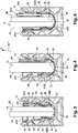
figure 3 est une vue en section selon un plan de coupe transversal vertical passant par une vis de serrage qui représente le dispositif de fixation de lafigure 2 mis en position dans un rail, la vis de serrage commandant le serrage de deux premiers coins ; - la
figure 4 est une vue en section selon un plan de coupe parallèle à celui de lafigure 3 et passant par un premier organe de renvoi en compression qui représente la chaine de transmission de l'effort de translation vertical depuis une vis jusqu'à un deuxième coin inférieur situé du côté opposé à la vis par rapport au panneau ; - la
figure 5 est une vue en section selon un plan de coupe parallèle à celui de lafigure 3 et passant par un deuxième organe de renvoi en traction qui représente la chaine de transmission de l'effort de translation vertical depuis un écrou jusqu'à un deuxième coin supérieur situé du côté opposé de l'écrou par rapport au panneau.
- the
figure 1 is a perspective view showing a vertical panel fixed in a rail by means of fixing devices made according to the teachings of the invention; - the
figure 2 is an exploded perspective view that represents the fastening device of thefigure 1 ; - the
figure 3 is a sectional view along a vertical transverse sectional plane passing through a clamping screw which represents the fastening device of thefigure 2 placed in position in a rail, the clamping screw controlling the tightening of two first corners; - the
figure 4 is a sectional view along a sectional plane parallel to that of thefigure 3 and passing through a first compression return member which represents the chain of transmitting the vertical translation force from a screw to a second lower corner located on the side opposite the screw relative to the panel; - the
figure 5 is a sectional view along a sectional plane parallel to that of thefigure 3 and passing through a second tension return member which represents the chain of transmission of the vertical translation force from a nut to a second upper corner located on the opposite side of the nut relative to the panel.
Dans la suite de la description, on adoptera à titre non limitatif des orientations longitudinale, verticale et transversale indiquées par le trièdre "L,V,T" des figures.In the remainder of the description, the longitudinal, vertical and transverse orientations indicated by the "L, V, T" trihedron of the figures will be adopted without limitation.
Dans la suite de la description, des éléments présentant une structure identique ou des fonctions analogues seront désignés par une même référence.In the remainder of the description, elements having an identical structure or similar functions will be designated by the same reference.
On a représenté à la
Le garde-corps 10 comporte un panneau 14 vertical et un rail 16 de support. Le panneau 14 est préférentiellement en verre. Il est maintenu verticalement dans le rail 16 de support par plusieurs dispositifs 18 de fixation. Chaque dispositif 18 de fixation est conçu pour permettre de fixer fermement le panneau 14 dans une position verticale et pour résister à des charges très importantes.The
Comme cela est illustré plus en détail à la
La rainure 20 présente un fond 22 de forme courbe concave, de préférence semi-circulaire, prolongée par deux faces 24, 26 verticales opposées agencées transversalement en vis-à-vis l'une de l'autre. La rainure 20 présente une ouverture supérieure. La largeur de la rainure 20 entre les deux faces latérales 24, 26 est supérieure à l'épaisseur du panneau 14. La première face 24 verticale est située du côté accessible du rail, tandis que la deuxième face 26 verticale est située du côté inaccessible du rail.The
Chaque dispositif 18 de fixation est conçu comme un module formé de plusieurs pièces dont certaines peuvent être préassemblées avant leur insertion dans la rainure 20. On décrit à présent un dispositif 18 de fixation en référence aux
Le dispositif 18 de fixation comporte au moins deux coins 34A, 34B ; 42A, 42B opposés qui sont destinés à serrer transversalement le panneau 14 vertical dans la rainure 20 longitudinale de réception.The fixing
Le dispositif 18 de fixation comporte aussi un berceau 30 qui est conçu pour enfourcher un chant 32 inférieur du panneau 14, comme cela est représenté à la
Chaque face 24, 26 verticale de la rainure comporte en outre une butée 28 en saillie qui est destiné à retenir verticalement le berceau 30 en fond de rainure 20.Each
Le berceau 30 est ici réalisé en matière plastique rigide.The
Le dispositif 18 de fixation comporte au moins un premier coin 34A ou 34B qui est intercalé entre la première face 24 verticale de la rainure 20 et une première face 36 du panneau 14, comme cela est illustré à la
Le premier coin 34A ou 34B présente au moins une face 38 inclinée qui est destinée à coopérer avec une rampe fixe pour permettre son serrage par coulissement vertical. La rampe est solidaire soit du rail 16 de support, soit du berceau 30.The
Le dispositif 18 de fixation comporte au moins un deuxième coin 42A ou 42B opposé monté en vis-à-vis du premier coin 34A, 34B de l'autre côté du panneau 14. Le deuxième coin 42A ou 42B est intercalé entre la deuxième face 26 verticale opposée de la rainure 20 et une deuxième face 44 opposée du panneau 14. La deuxième face 36 du panneau 14 est tournée vers le côté inaccessible de la dalle 12.The fixing
Le deuxième coin 42A ou 42B présente au moins une face 46 inclinée qui est destinée à coopérer par glissement avec une rampe fixe pour permettre son serrage par coulissement vertical. La rampe est solidaire soit du rail 16 de support, soit du berceau 30.The
Le coulissement vertical de chaque premier coin 34A, 34B et deuxième coin 42A, 42B permet ainsi de régler la verticalité du panneau 14 en même temps que de le fixer en position verticale par serrage transversal entre les coins 34A, 34B ; 42A, 42B.The vertical sliding of each
Au moins le deuxième coin 42A, 42B est commandé en coulissement par un ensemble 50 vis-écrou qui est destiné à produire un effort de translation vertical du deuxième coin 42A, 42B dans une direction de serrage entre le panneau 14 et la deuxième face 26 de la rainure 20.At least the
Chaque coin 34A, 34B, 42A, 42B est coulissant le long d'une course très courte de l'ordre de quelques millimètres.Each
Cependant, le réglage de l'ensemble 50 vis-écrou ne peut être effectué qu'après avoir inséré le panneau 14 dans la rainure 20. Le deuxième coin 42A, 42B est alors situé du côté inaccessible du panneau 14. Dans l'état de la technique, l'ensemble vis-écrou est agencé du côté inaccessible du panneau. Le serrage du deuxième coin ne pouvait s'effectué qu'en ayant recours à des moyens d'accès tels qu'un échafaudage ou une nacelle.However, the adjustment of the
La présente invention propose un agencement pour la fixation du panneau 14 dans le rail 16 de support permettant de régler le serrage du deuxième coin 42A, 42B depuis le côté accessible du panneau 14.The present invention provides an arrangement for fixing the
L'invention propose ainsi d'agencer l'ensemble 50 vis-écrou du même côté du panneau 14 que le premier coin 32A, 32B. L'effort de translation produit par l'ensemble 50 vis-écrou est alors transmis au deuxième coin 42A, 42B par l'intermédiaire d'un organe de renvoi qui est interposé entre un chant inférieur du panneau 14 et le fond 22 de la rainure 20.The invention thus proposes to arrange the
Dans le mode de réalisation représenté aux figures, le dispositif 18 de fixation comporte plusieurs premiers coins 34A, 34B. Il comporte ainsi, de manière non limitative, un premier coin 34A supérieur et deux premiers coins 34B inférieurs.In the embodiment shown in the figures, the fixing
Le coin 34A supérieur coopère avec une rampe 52 qui est formé dans la partie supérieure de la première face 24 de la rainure 20. La rampe 52 est conçue pour que le serrage du coin 34A entre le panneau 14 et la première face 24 de la rainure 20 se produise lors de son coulissement vers le bas.The
Les coins 34B inférieurs coopèrent chacun avec une rampe 54 associée du berceau 30 qui prend appui transversalement contre la première face 24 de la rainure 20. Les coins 34B inférieurs sont plus particulièrement interposés entre la rampe 54 et le panneau 14. La rampe 54 est conçue pour que le serrage du coin 34B entre le panneau 14 et la première face 24 de la rainure 20 se produise lors de son coulissement vers le haut.The
Le coulissement du coin 34A supérieur et celui de chaque coin 34B inférieur est réalisé au moyen de deux vis 56 verticales. Chaque vis 56 est reçue dans un orifice 58 lisse associé percé dans le coin 34A supérieur au droit de chaque coin 34B inférieur. L'extrémité inférieure de chaque vis 56 est vissée dans un orifice 60 de chaque coin 34B inférieur. La vis 50A est par exemple vissée à force dans l'orifice 60. En variante l'orifice 60 est taraudé. En tous les cas, la vis 50A est en prise avec le coin 34B inférieur associé.The sliding of the
Ainsi, lorsque les vis 56 sont vissées, les coins 34B inférieurs, bloqués en rotation, coulissent vers le haut jusqu'à être coincés entre la rampe 54 et le panneau 14. En poursuivant le vissage, la tête de la vis prend appui sur le coin 34A supérieur pour le faire coulisser vers le bas jusqu'à être coincé entre la première face 24 de la rainure 20 et le panneau 14. Le vissage peut être poursuivi jusqu'à ce que les coins 34A, 34B soient serrés avec l'effort vertical désiré pour obtenir la fixation verticale du panneau 14. Outre la rapidité de fixation, ce système de réglage de la position du coin 34A et de chaque coin 34B avec une même vis 56 permet d'équilibrer l'effort de serrage appliqué par chaque coin 34A, 34B contre le panneau 14.Thus, when the
Le dispositif 18 de fixation comporte aussi deux deuxièmes coins 42A, 42B. Il comporte ainsi un deuxième coin 42A supérieur et un deuxième coin 42B inférieur. Ces deuxièmes coins 42A, 42B sont agencés en vis-à-vis des premiers coins 34A, 34B pour permettent un serrage du panneau 14 sur toute la hauteur de la portion de panneau 14 insérée dans la rainure 20. La fixation du panneau 14 dans le rail 16 de support est ainsi très solide et la fixation du panneau 14 est susceptible de résister même lorsqu'un effort transversal très important est appliqué à son bord supérieur.The fixing
Le deuxième coin 42A supérieur coopère avec une rampe 62 qui est formé dans la partie supérieure de la deuxième face 26 de la rainure 20. La rampe 62 est conçue pour que le serrage du deuxième coin 42A supérieur entre le panneau 14 et la deuxième face 26 de la rainure 20 se produise lors de son coulissement vers le bas.The second
Le coin 42B inférieur coopère avec une rampe 64 associée du berceau 30 qui prend appui transversalement contre la deuxième face 26 de la rainure 20. Le deuxième coin 42B inférieur est plus particulièrement interposé entre la rampe 64 et le panneau 14. La rampe 64 est conçue pour que le serrage du deuxième coin 42B inférieur entre le panneau 14 et la deuxième face 26 de la rainure 20 se produise lors de son coulissement vers le haut.The
L'ensemble 50 vis-écrou commande ici simultanément le coulissement des deux deuxièmes coins 42A, 42B. Il comporte une vis 50A verticale et un écrou 50B. La tête de vis est dirigée vers le haut. L'ensemble 50 vis-écrou est interposé entre la première face 36 du panneau et la première face 24 de la rainure 20.The
Le coulissement du deuxième coin 42B inférieur est ici commandé par le déplacement vertical de la vis 50A lors de son vissage. Le déplacement vertical de la vis 50A produit un effort de translation vertical qui est orienté vers le bas. Cet effort de translation vertical est transmis au deuxième coin 42B inférieur avec un changement de direction de manière à devenir un effort de translation vertical dirigé vers le haut afin de faire coulisser le deuxième coin 42B inférieur vers l'ouverture supérieure de la rainure 20.The sliding of the second
La transmission de l'effort de translation vertical est réalisée au moyen d'au moins un premier organe 66 de renvoi. Dans le mode de réalisation représenté à la
Comme représenté à la
L'organe 66 de renvoi présente ici la forme d'un segment courbe qui est agencé dans un canal de guidage formé dans le berceau 30. La face 68 inférieure de l'organe 66 de renvoi est ici en appui contre une cloison inférieure du berceau 30 qui est interposée entre ledit organe 66 de renvoi et le fond 22 de la rainure 20. Cette cloison inférieure présente une forme d'arc de cercle complémentaire du fond 22 de la rainure 20. Cet agencement permet d'éviter que l'organe 66 de renvoi ne soit appuyé directement contre le fond 22 de la rainure 20, ce qui provoquerait un soulèvement du berceau 30 lors du serrage du coin 42B correspondant. Au contraire, en prenant appui sur une cloison inférieure du berceau 30, le berceau 30 demeure contre le fond 22 de la rainure 20 quel que soit l'état de serrage du coin 42B correspondant.The
L'organe 66 de renvoi présente une première extrémité 70 qui est agencée du côté accessible panneau 14 et qui est destinée à être sollicitée par la vis 50A. Il comporte aussi une deuxième extrémité 72 qui est destinée à solliciter le deuxième coin 42B inférieur.The
Pour pouvoir pousser le coin 42B inférieur vers sa position de serrage, c'est-à-dire vers le haut, l'organe 66 de renvoi travaille en compression lors du serrage du coin 42B.To be able to push the
Dans le mode de réalisation représenté aux figures, les organes 66 de renvoi sont sollicités par l'intermédiaire d'un cavalier 74 monté coulissant verticalement dans la rainure 20 du côté accessible du panneau 14. Le cavalier comporte une traverse supérieure qui est équipée d'un orifice lisse destiné à recevoir la tige filetée de la vis 50A. La tête de la vis 50A repose sur une face supérieure de la traverse. Le cavalier 74 comporte deux pattes parallèles qui s'étendent verticalement vers le bas jusqu'à une extrémité inférieure de sollicitation des premières extrémités 70 des organes 66 de renvoi à la faveur de canaux de guidage réservés dans le berceau 30.In the embodiment shown in the figures, the
Les premiers coins 34A inférieurs sont agencés longitudinalement de part et d'autre du cavalier 74. Un passage vertical est réservé dans le premier coin 34A supérieur pour guider le cavalier 74 en coulissement vertical.The first
En variante non représentée de l'invention, au moins un organe 66 de renvoi est sollicité directement par l'extrémité inférieure de la vis 50A.As a variant not shown of the invention, at least one
Selon une autre variante non représentée de l'invention, le premier organe de renvoi est un levier qui prend appui contre un point fixe, par exemple réalisé dans le fond du berceau. Le levier pivote ainsi autour d'un axe longitudinal situé sous le chant inférieur du panneau.According to another variant not shown of the invention, the first return member is a lever which bears against a fixed point, for example made in the bottom of the cradle. The lever thus pivots about a longitudinal axis located under the lower edge of the panel.
Le coulissement du deuxième coin 42A supérieur est ici commandé par le déplacement vertical de l'écrou 50B lors du vissage de la vis 50A. Le déplacement vertical de l'écrou 50B produit un effort de translation vertical qui est orienté vers le haut. Cet effort de translation vertical est transmis au deuxième coin 42A supérieur avec un changement de direction de manière à devenir un effort de translation vertical dirigé vers le bas afin de faire coulisser le deuxième coin 42A supérieur en direction du fond de la rainure 20.The sliding of the second
La transmission de l'effort de translation vertical est réalisée au moyen d'au moins un deuxième organe 76 de renvoi. Dans le mode de réalisation représenté à la
Le deuxième organe de renvoi 76 est un organe souple qui travaille en traction autour d'un support fixe de renvoi d'angle qui contourne le chant 32 inférieur du panneau 14 par le bas.The
Le support fixe de renvoi d'angle est formé par la face inférieure du berceau 30. Au besoin, une chemise (non représentée) de matériau résistant et/ou glissant peut être interposée entre le deuxième organe 76 de renvoi et la face inférieure du berceau 30. La face inférieure du berceau 30 présente une forme d'arc de cercle. Ainsi, le tronçon du deuxième organe 76 de renvoi qui est située contre le support fixe de renvoi d'angle est coulissante le long d'une trajectoire en arc de cercle, tandis que les deux brin d'extrémité de l'organe 76 de renvoi sont coulissant verticalement.The fixed angle deflection support is formed by the underside of the
Le deuxième organe 76 de renvoi est ici formé par une lame souple, par exemple une lame de ressort métallique ou une lame en matériau composite. La lame est agencée à plat contre la face inférieure du berceau 30.The
En variante non représentée, la lame formant le deuxième organe de renvoi est suffisamment large pour envelopper les premiers organes de renvoi. Ainsi, les premiers organes de renvoi glissent contre une face supérieure de la lame formant le deuxième organe de renvoi au lieu de glisser contre une paroi inférieure du berceau.In variant not shown, the blade forming the second return member is large enough to envelop the first return members. Thus, the first return members slide against an upper face of the blade forming the second return member instead of sliding against a lower wall of the cradle.
Selon une autre variante non représentée de l'invention, le deuxième organe de renvoi est formé par un câble.According to another variant not shown of the invention, the second return member is formed by a cable.
Selon encore une autre variante non représentée de l'invention, l'organe de renvoi est formé par une chaîne d'éléments articulés.According to yet another variant not shown of the invention, the return member is formed by a chain of articulated elements.
Une première extrémité 78 du deuxième organe 76 de renvoi est agencée du côté accessible du panneau 14. Cette première extrémité 78 est solidaire en coulissement vertical de l'écrou 50B. Dans l'exemple représenté aux figures, la première extrémité 78 est recourbée en forme de crochet pour être accrochée à l'écrou 50B.A
Une deuxième extrémité 80 du deuxième organe 76 de renvoi est agencée du côté inaccessible du panneau 14. Cette deuxième extrémité 80 est solidaire en coulissement vertical du deuxième coin 42A supérieur. Dans l'exemple représenté aux figures, la première extrémité 80 est recourbée en forme de crochet pour être accrochée au deuxième coin 42A supérieur.A
On comprendra bien entendu que les extrémités du deuxième organe 76 de renvoi peuvent être fixées par d'autre moyens que l'accrochage, tels que le soudage, le collage, le surmoulage, le coincement de formes complémentaires...It will of course be understood that the ends of the
L'écrou 50B est bien entendu conçu pour être immobilisé en rotation par rapport au rail 16. L'écrou 50B est ici logé entre les pattes du cavalier 74 afin de permettre son coulissement vertical le long de la vis 50A lors de son vissage/dévissage.The
Lors du montage du panneau 14 dans le rail 16, le dispositif 18 de fixation est préassemblé. Ainsi, les coins 34B, 42A, 42B sont mis en position dans le berceau 30, à l'exception du premier coin 34A supérieur. L'ensemble 50 vis-écrou est également assemblé ainsi que les organes 66, 76 de renvoi. Le module ainsi préassemblé est inséré dans la rainure 20 du rail 16. Le panneau 14 est ensuite reçu dans le berceau 30 entre les coins 34B, 42A, 42B. Ainsi, tous les éléments situés du côté inaccessible du panneau 14 sont mis en position avant la mise en place du panneau 14. Le premier coin 34A supérieur est ensuite mis en position avec les vis 56 de serrage.When mounting the
Lors du serrage des deuxièmes coins 42A, 42B, la vis 50A est vissée dans l'écrou 50B. Cette opération provoque le déplacement mutuel de la vis 50A vers le bas et de l'écrou 50B vers le haut.When tightening the
Il s'ensuit que la tête de la vis 50A appui sur le cavalier 74 qui sollicite vers le bas, par l'intermédiaire de ses pattes les premiers organes 66 de renvoi. La face 68 de guidage de chaque premier organe 66 de renvoi glisse contre la cloison inférieure du berceau 30 de manière que la deuxième extrémité 72 vienne solliciter vers le haut le deuxième coin 42B inférieur dans sa position de serrage. Ainsi, l'effort de translation vertical est produit par le déplacement de la vis 50A vers le bas, une première extrémité 70 de l'organe 66 de renvoi étant sollicitée en appui par la vis 50A, ici par l'intermédiaire du cavalier 74, et une deuxième extrémité 72 de l'organe 66 de renvoi sollicitant le coin 42B par appui.It follows that the head of the
Simultanément, l'écrou 50B se déplace verticalement vers le haut en tirant sur le deuxième organe 76 de renvoi. Ce deuxième organe 76 de renvoi, prenant appui sur la face inférieure du berceau 30, tire le deuxième coin 42A supérieur vers le bas jusqu'à sa position de serrage. Ainsi, l'effort de translation vertical est produit par déplacement de l'écrou 50B verticalement vers le haut, une première extrémité 78 de l'organe de renvoi étant solidaire en déplacement avec l'écrou 50B et une deuxième extrémité 80 de l'organe étant solidaire en déplacement avec le deuxième coin 42A supérieur.Simultaneously, the
La commande du serrage des deuxièmes coins 42A, 42B par une ensemble 50 vis-écrou commun permet de régler rapidement le serrage des coins 42A, 42B par une seule opération de vissage. En outre, cela garantit que l'effort de serrage des coins 42A, 42B est équilibré.Controlling the tightening of the
Ainsi, les deuxième coins 42A, 42B agencés du côté inaccessible du panneau 14 sont serrés au moyen de la vis 50A qui est agencée du côté accessible du panneau 14. Plus particulièrement, la vis 50A est agencée à proximité des vis 56 de serrage des premiers coins 34A, 34B. Ainsi, un opérateur peut effectuer rapidement le réglage de la verticalité et la fixation du panneau 14 sans avoir à se déplacer. Les têtes de vis 50A, 56 sont accessibles par l'ouverture supérieure de la rainure 20 du même côté du panneau 14.Thus, the
En variante non représentée de l'invention, le dispositif 18 de fixation comporte un seul deuxième coin 42A ou 42B qui peut être serré soit par coulissement vers le bas, soit par coulissement vers le haut. Un tel mode de réalisation est notamment applicable lorsque chaque dispositif de fixation comporte seulement deux coins opposés agencés chacun d'un côté du panneau.In a variant not shown of the invention, the fixing
L'invention a été décrite en application à la fixation d'un panneau de garde-corps dans un rail. On comprendra qu'elle est applicable à tout autre type de dispositif comportant un panneau devant être fixé dans un rail, par exemple une cloison en verre pour un guichet, un totem d'enseigne, etc.The invention has been described in application to the attachment of a railing panel in a rail. It will be understood that it is applicable to any other type of device comprising a panel to be fixed in a rail, for example a glass partition for a window, a sign totem, etc.
Claims (10)
- Arrangement for the fastening of a vertical panel (14) in a longitudinal receiving groove (20) by transverse clamping between at least two transversely opposite wedges (34A, 34B; 42A, 42B), with the arrangement comprising:- at least one first wedge (34A, 34B) which is interposed between a first vertical face (24) of the groove (20) and a first face (36) of the panel (14);- at least one opposite second wedge (42A, 42B) mounted facing the first wedge (34A, 34B) of the other side of the panel (14), with the second wedge (42A, 42B) being interposed between a second opposite vertical face (26) of the groove (20) and a second opposite face (44) of the panel (14), with the second wedge (42A, 42B) cooperating via vertical sliding with a second fixed ramp (46, 62) in order to adjust the verticality of the panel (14);- at least one screw-nut assembly (50) intended to produce a vertical translation force of the second wedge (42A, 42B) in a clamping direction between the panel (14) and the second face (26) of the groove (20);characterised in that the screw-nut assembly (50) is arranged on the same side of the panel (14) as the first wedge (34A, 34B), with the translation force being transmitted to the second wedge (42A, 42B) by the intermediary of a mobile deflection member (66, 76) which is interposed between a lower edge (32) of the panel (14) and the bottom (22) of the groove (20).
- Arrangement according to the preceding claim, characterised in that the deflection member (66) is a rigid part rotatably mounted about a longitudinal axis between the bottom (22) of the groove (20) and the lower edge (32) of the panel (14).
- Arrangement according to claim 1, characterised in that the deflection member (76) is a flexible member that works in traction around a fixed angle deflection support (30) which bypasses the lower edge (32) of the panel (14).
- Arrangement according to the preceding claim, characterised in that the fixed angle deflection support is carried out in a crib (30) that straddles the lower edge (32) of the panel (14) and which is inserted between the panel (14) and the bottom (22) of the groove (20).
- Arrangement according to any of claims 3 to 4, characterised in that the clamping direction of the second wedge (42A) is directed towards the bottom of the groove, with the deflection member (76) working in traction during the clamping of the wedge (42A).
- Arrangement according to the preceding claim, characterised in that the vertical translation force is produced by displacement of the nut (50B) vertically towards an upper opening of the groove (20), a first end (78) of the deflection member (76) being integral in displacement with the nut (50B) and a second end (80) of the deflection member (76) being integral in displacement with said second wedge (42A).
- Arrangement according to claim 2, characterised in that the clamping direction of at least a second opposite wedge (42B) is directed towards an upper opening of the groove (20), with the deflection member (66) working in compression during the clamping of the wedge (42B).
- Arrangement according to the preceding claim, characterised in that the deflection member slides along a trajectory in an arc of circle parallel to the bottom (22) of the groove (20).
- Arrangement according to the preceding claim characterised in that the vertical translation force is produced by the displacement of the screw (50A) towards the bottom (22) of the groove (20), with a first end (70) of the deflection member being urged against by the screw (50A) and a second end (72) of the deflection member (66) urging the wedge (42B) pressing.
- Arrangement according to any preceding claim, characterised in that it comprises two second opposite wedges (42A, 42B) which have opposite vertical clamping directions, each second wedge (42A, 42B) being controlled in sliding respectively by the nut (50B) and by the screw(50A) of the same screw-nut assembly (50).
Applications Claiming Priority (1)
| Application Number | Priority Date | Filing Date | Title |
|---|---|---|---|
| FR1661143A FR3058743B1 (en) | 2016-11-17 | 2016-11-17 | ARRANGEMENT FOR FIXING A PANEL INTO A GROOVE USING TWO OPPOSITE CORNERS |
Publications (2)
| Publication Number | Publication Date |
|---|---|
| EP3323958A1 EP3323958A1 (en) | 2018-05-23 |
| EP3323958B1 true EP3323958B1 (en) | 2019-09-11 |
Family
ID=57590701
Family Applications (1)
| Application Number | Title | Priority Date | Filing Date |
|---|---|---|---|
| EP17192624.9A Active EP3323958B1 (en) | 2016-11-17 | 2017-09-22 | Arrangement for attaching a panel to a groove by two opposing wedges |
Country Status (6)
| Country | Link |
|---|---|
| US (1) | US10830264B2 (en) |
| EP (1) | EP3323958B1 (en) |
| CA (1) | CA2984283C (en) |
| DK (1) | DK3323958T3 (en) |
| ES (1) | ES2751058T3 (en) |
| FR (1) | FR3058743B1 (en) |
Cited By (2)
| Publication number | Priority date | Publication date | Assignee | Title |
|---|---|---|---|---|
| US10883274B1 (en) * | 2019-09-11 | 2021-01-05 | Vancouver Glazing Hardware Inc. | Horizontal panel alignment system |
| DE202024103142U1 (en) | 2024-06-12 | 2024-07-31 | Onlevel Holding Bv | Device for fastening a vertically aligned railing plate by wedging between the inner walls of the guide channel of a floor support profile |
Families Citing this family (18)
| Publication number | Priority date | Publication date | Assignee | Title |
|---|---|---|---|---|
| US10184267B2 (en) * | 2016-07-01 | 2019-01-22 | Chingyao Kuo | Supporting mechanism for glass fence |
| DE102016112775B3 (en) * | 2016-07-12 | 2017-10-05 | Bohle Ag | Device for fastening a plate-shaped component in a receiving groove of a mounting rail |
| IL247757B (en) * | 2016-09-11 | 2020-11-30 | Tomak Ltd | System and method for plate alignment |
| DE202017101856U1 (en) * | 2017-03-30 | 2017-04-27 | Häfele Berlin Gmbh & Co Kg | Backplane Einsteckkeil |
| GB2555169B (en) * | 2017-07-21 | 2019-10-23 | Pure Vista Ltd | Panel support system and method |
| GB2571143B (en) * | 2018-03-29 | 2020-03-25 | Pure Vista Ltd | Panel support system and method |
| US11053688B2 (en) * | 2018-09-19 | 2021-07-06 | Euro Ornamental Forgings Inc. | Adjustable glass grip |
| WO2020100094A1 (en) | 2018-11-16 | 2020-05-22 | Sb Ingenierie | Fixing structure for fixing a panel, in particular a glass panel |
| FR3088660B1 (en) | 2018-11-16 | 2020-12-25 | Sb Ingenierie | FIXING STRUCTURE INTENDED TO FIX A PANEL, IN PARTICULAR A GLASS PANEL |
| FR3088661B1 (en) | 2018-11-16 | 2021-01-29 | Sb Ingenierie | PUNCTUAL CLAMP INTENDED TO FIX A GLASS PANEL |
| FR3088662A1 (en) | 2018-11-16 | 2020-05-22 | Sb Ingenierie | FIXING STRUCTURE FOR FIXING A PANEL, IN PARTICULAR A GLASS PANEL |
| FR3088663B1 (en) | 2018-11-16 | 2020-11-06 | Sb Ingenierie | FIXING STRUCTURE INTENDED TO FIX A PANEL, IN PARTICULAR A GLASS PANEL |
| US20220170271A1 (en) * | 2019-03-18 | 2022-06-02 | Illuminated Balustrade Australia Pty Ltd | Wall Supporting Device |
| USD934450S1 (en) * | 2019-04-19 | 2021-10-26 | Sb Ingenierie | Barrier support |
| FR3096704B1 (en) * | 2019-05-31 | 2021-05-07 | Sb Ingenierie | "Arrangement for fixing a panel in a rail by clamping outside corners from an inside side of the panel" |
| WO2021113875A1 (en) * | 2019-12-05 | 2021-06-10 | R&B Wagner, Inc. | Leveling partition mounting system |
| FR3115549B1 (en) | 2020-10-22 | 2022-10-28 | Sb Ingenierie | Device for fixing a panel in a groove by clamping wedges arranged on one side of the panel only |
| USD1024355S1 (en) | 2020-11-26 | 2024-04-23 | Peak Innovations Inc. | Spigot for a glass railing system |
Citations (6)
| Publication number | Priority date | Publication date | Assignee | Title |
|---|---|---|---|---|
| US20060163892A1 (en) | 2002-01-14 | 2006-07-27 | Nguyen Hoa N | Clamping device for lifting slab, panel or sheet material |
| WO2013121330A2 (en) | 2012-02-14 | 2013-08-22 | Metalglas Bonomi S.R.L. | Regulation and/or locking device for a plate |
| EP2921607A2 (en) | 2014-02-26 | 2015-09-23 | SB Ingénierie | Device for attaching a panel in a support rail |
| WO2015145477A1 (en) | 2014-03-25 | 2015-10-01 | Ind.I.A. S.P.A. | Locking and regulation device for panels and slabs |
| US20160186790A1 (en) | 2013-07-31 | 2016-06-30 | Andrzej Poradzisz | Support for rigid panel |
| WO2018011309A1 (en) | 2016-07-12 | 2018-01-18 | Bohle Ag | Device for fastening a panel-shaped component in a receiving groove of a carrying rail |
Family Cites Families (4)
| Publication number | Priority date | Publication date | Assignee | Title |
|---|---|---|---|---|
| DE102006028766B4 (en) * | 2006-06-23 | 2017-02-16 | Bernhard Feigl | Holding device for a plate |
| EP3009580B1 (en) * | 2014-10-17 | 2017-03-22 | Compas S.R.L. | System for fixing slab-like elements for railings, balustrades and parapets in general and method using it |
| GB2528147B (en) * | 2015-03-09 | 2017-05-24 | Pure Vista Ltd | System and method for adjusting alignment of a panel |
| CN107567217B (en) | 2016-06-30 | 2019-11-22 | 比亚迪股份有限公司 | A kind of shell and its preparation method and application |
-
2016
- 2016-11-17 FR FR1661143A patent/FR3058743B1/en active Active
-
2017
- 2017-09-22 DK DK17192624T patent/DK3323958T3/en active
- 2017-09-22 ES ES17192624T patent/ES2751058T3/en active Active
- 2017-09-22 EP EP17192624.9A patent/EP3323958B1/en active Active
- 2017-10-30 CA CA2984283A patent/CA2984283C/en active Active
- 2017-11-16 US US15/815,566 patent/US10830264B2/en active Active
Patent Citations (6)
| Publication number | Priority date | Publication date | Assignee | Title |
|---|---|---|---|---|
| US20060163892A1 (en) | 2002-01-14 | 2006-07-27 | Nguyen Hoa N | Clamping device for lifting slab, panel or sheet material |
| WO2013121330A2 (en) | 2012-02-14 | 2013-08-22 | Metalglas Bonomi S.R.L. | Regulation and/or locking device for a plate |
| US20160186790A1 (en) | 2013-07-31 | 2016-06-30 | Andrzej Poradzisz | Support for rigid panel |
| EP2921607A2 (en) | 2014-02-26 | 2015-09-23 | SB Ingénierie | Device for attaching a panel in a support rail |
| WO2015145477A1 (en) | 2014-03-25 | 2015-10-01 | Ind.I.A. S.P.A. | Locking and regulation device for panels and slabs |
| WO2018011309A1 (en) | 2016-07-12 | 2018-01-18 | Bohle Ag | Device for fastening a panel-shaped component in a receiving groove of a carrying rail |
Cited By (2)
| Publication number | Priority date | Publication date | Assignee | Title |
|---|---|---|---|---|
| US10883274B1 (en) * | 2019-09-11 | 2021-01-05 | Vancouver Glazing Hardware Inc. | Horizontal panel alignment system |
| DE202024103142U1 (en) | 2024-06-12 | 2024-07-31 | Onlevel Holding Bv | Device for fastening a vertically aligned railing plate by wedging between the inner walls of the guide channel of a floor support profile |
Also Published As
| Publication number | Publication date |
|---|---|
| US20180135669A1 (en) | 2018-05-17 |
| CA2984283A1 (en) | 2018-05-17 |
| CA2984283C (en) | 2021-11-16 |
| FR3058743B1 (en) | 2019-01-25 |
| ES2751058T3 (en) | 2020-03-30 |
| US10830264B2 (en) | 2020-11-10 |
| EP3323958A1 (en) | 2018-05-23 |
| DK3323958T3 (en) | 2019-10-28 |
| FR3058743A1 (en) | 2018-05-18 |
Similar Documents
| Publication | Publication Date | Title |
|---|---|---|
| EP3323958B1 (en) | Arrangement for attaching a panel to a groove by two opposing wedges | |
| EP3976901B1 (en) | Arrangement for securing a panel in a rail by tightening outer wedges from an inner side of the panel | |
| FR2979881A1 (en) | STEERING COLUMN COMPRISING AN IMPROVED DEPTH BLOCKING MECHANISM. | |
| EP3988736A1 (en) | Device for fastening a panel into a groove by clamping corners arranged along one side of the panel | |
| EP1801323B1 (en) | Device for fixing a rail on a post | |
| FR2900897A1 (en) | SLIDING FIXATION OF A FENDER TO A MOTOR VEHICLE WHITE BOX AND METHOD OF FASTENING USING SUCH A FIXATION | |
| EP2942237A1 (en) | Device for anchoring a roof bar end for a motor vehicle provided with longitudinal roof bars | |
| EP1517826B1 (en) | Structural element comprising a vertical member securing nut and the corresponding motor vehicle | |
| FR2658473A1 (en) | DEVICE FOR LOCKING A TUBULAR MEMBER AND IN PARTICULAR A STEERING COLUMN FOR A MOTOR VEHICLE. | |
| EP1830073B1 (en) | Device for attaching two pieces, one pinned against the other, using a clip | |
| EP1359082B1 (en) | Position adjustment device of a motor vehicle steering column | |
| FR3061882A1 (en) | FRONT OPTICAL BLOCK MOUNT ADAPTED TO CUT THE TRACK OF THE OPTICAL BLOCK DURING A FRONT SHOCK OF A VEHICLE | |
| WO2000048895A1 (en) | Device for fixing a fender flare integrated in a bumper | |
| EP2322407B1 (en) | Improved device for locking in position an adjustable steering column of a vehicle | |
| FR3032679A1 (en) | DEVICE FOR STOPPING A VEHICLE DOOR IN AN OPENING POSITION | |
| FR2762350A1 (en) | Adjuster for angular position of motor vehicle door window | |
| FR3019600A1 (en) | SYSTEM FOR FIXING AN OBJECT IN A RAIL OF A SUPPORT | |
| EP3807546B1 (en) | Fastening device comprising a panel edge adapted for receiving a nut clamp and a nut clamp | |
| OA20647A (en) | Device for fixing a panel in a groove by clamping wedges arranged on one side of the panel only. | |
| EP0459849A1 (en) | Adjustable mounting for motor vehicule bumper | |
| FR3083485A1 (en) | Multi-piece frame for a sliding vehicle roof or sliding / tilting vehicle roof and method for mounting a multi-piece frame | |
| FR2671748A1 (en) | Device for adjusting the length of a mast or the like and for locking, in the desired position, a block which slides on the mast | |
| FR2855139A1 (en) | Motor vehicles steering column position maintaining device, has flexible units that are compressed until rigid units come into contact and slightly penetrates sliding face in locked position of wheel | |
| FR2682738A1 (en) | End-fitting for connecting between two sections | |
| EP1361138A1 (en) | Vehicle steering-column assembly and vehicle with such an assembly |
Legal Events
| Date | Code | Title | Description |
|---|---|---|---|
| PUAI | Public reference made under article 153(3) epc to a published international application that has entered the european phase |
Free format text: ORIGINAL CODE: 0009012 |
|
| STAA | Information on the status of an ep patent application or granted ep patent |
Free format text: STATUS: THE APPLICATION HAS BEEN PUBLISHED |
|
| AK | Designated contracting states |
Kind code of ref document: A1 Designated state(s): AL AT BE BG CH CY CZ DE DK EE ES FI FR GB GR HR HU IE IS IT LI LT LU LV MC MK MT NL NO PL PT RO RS SE SI SK SM TR |
|
| AX | Request for extension of the european patent |
Extension state: BA ME |
|
| STAA | Information on the status of an ep patent application or granted ep patent |
Free format text: STATUS: REQUEST FOR EXAMINATION WAS MADE |
|
| 17P | Request for examination filed |
Effective date: 20181115 |
|
| RBV | Designated contracting states (corrected) |
Designated state(s): AL AT BE BG CH CY CZ DE DK EE ES FI FR GB GR HR HU IE IS IT LI LT LU LV MC MK MT NL NO PL PT RO RS SE SI SK SM TR |
|
| REG | Reference to a national code |
Ref country code: DE Ref legal event code: R079 Ref document number: 602017006916 Country of ref document: DE Free format text: PREVIOUS MAIN CLASS: E04F0011180000 Ipc: F16B0002140000 |
|
| GRAP | Despatch of communication of intention to grant a patent |
Free format text: ORIGINAL CODE: EPIDOSNIGR1 |
|
| STAA | Information on the status of an ep patent application or granted ep patent |
Free format text: STATUS: GRANT OF PATENT IS INTENDED |
|
| RIC1 | Information provided on ipc code assigned before grant |
Ipc: F16B 2/14 20060101AFI20190308BHEP Ipc: E04F 11/18 20060101ALI20190308BHEP Ipc: F16B 9/02 20060101ALI20190308BHEP |
|
| INTG | Intention to grant announced |
Effective date: 20190327 |
|
| GRAS | Grant fee paid |
Free format text: ORIGINAL CODE: EPIDOSNIGR3 |
|
| GRAA | (expected) grant |
Free format text: ORIGINAL CODE: 0009210 |
|
| STAA | Information on the status of an ep patent application or granted ep patent |
Free format text: STATUS: THE PATENT HAS BEEN GRANTED |
|
| AK | Designated contracting states |
Kind code of ref document: B1 Designated state(s): AL AT BE BG CH CY CZ DE DK EE ES FI FR GB GR HR HU IE IS IT LI LT LU LV MC MK MT NL NO PL PT RO RS SE SI SK SM TR |
|
| REG | Reference to a national code |
Ref country code: GB Ref legal event code: FG4D Free format text: NOT ENGLISH |
|
| REG | Reference to a national code |
Ref country code: CH Ref legal event code: EP |
|
| REG | Reference to a national code |
Ref country code: AT Ref legal event code: REF Ref document number: 1178814 Country of ref document: AT Kind code of ref document: T Effective date: 20190915 |
|
| REG | Reference to a national code |
Ref country code: DE Ref legal event code: R096 Ref document number: 602017006916 Country of ref document: DE |
|
| REG | Reference to a national code |
Ref country code: IE Ref legal event code: FG4D Free format text: LANGUAGE OF EP DOCUMENT: FRENCH |
|
| REG | Reference to a national code |
Ref country code: DK Ref legal event code: T3 Effective date: 20191024 |
|
| REG | Reference to a national code |
Ref country code: NL Ref legal event code: FP |
|
| REG | Reference to a national code |
Ref country code: LT Ref legal event code: MG4D |
|
| PG25 | Lapsed in a contracting state [announced via postgrant information from national office to epo] |
Ref country code: FI Free format text: LAPSE BECAUSE OF FAILURE TO SUBMIT A TRANSLATION OF THE DESCRIPTION OR TO PAY THE FEE WITHIN THE PRESCRIBED TIME-LIMIT Effective date: 20190911 Ref country code: SE Free format text: LAPSE BECAUSE OF FAILURE TO SUBMIT A TRANSLATION OF THE DESCRIPTION OR TO PAY THE FEE WITHIN THE PRESCRIBED TIME-LIMIT Effective date: 20190911 Ref country code: NO Free format text: LAPSE BECAUSE OF FAILURE TO SUBMIT A TRANSLATION OF THE DESCRIPTION OR TO PAY THE FEE WITHIN THE PRESCRIBED TIME-LIMIT Effective date: 20191211 Ref country code: LT Free format text: LAPSE BECAUSE OF FAILURE TO SUBMIT A TRANSLATION OF THE DESCRIPTION OR TO PAY THE FEE WITHIN THE PRESCRIBED TIME-LIMIT Effective date: 20190911 Ref country code: BG Free format text: LAPSE BECAUSE OF FAILURE TO SUBMIT A TRANSLATION OF THE DESCRIPTION OR TO PAY THE FEE WITHIN THE PRESCRIBED TIME-LIMIT Effective date: 20191211 Ref country code: HR Free format text: LAPSE BECAUSE OF FAILURE TO SUBMIT A TRANSLATION OF THE DESCRIPTION OR TO PAY THE FEE WITHIN THE PRESCRIBED TIME-LIMIT Effective date: 20190911 |
|
| PG25 | Lapsed in a contracting state [announced via postgrant information from national office to epo] |
Ref country code: LV Free format text: LAPSE BECAUSE OF FAILURE TO SUBMIT A TRANSLATION OF THE DESCRIPTION OR TO PAY THE FEE WITHIN THE PRESCRIBED TIME-LIMIT Effective date: 20190911 Ref country code: GR Free format text: LAPSE BECAUSE OF FAILURE TO SUBMIT A TRANSLATION OF THE DESCRIPTION OR TO PAY THE FEE WITHIN THE PRESCRIBED TIME-LIMIT Effective date: 20191212 Ref country code: AL Free format text: LAPSE BECAUSE OF FAILURE TO SUBMIT A TRANSLATION OF THE DESCRIPTION OR TO PAY THE FEE WITHIN THE PRESCRIBED TIME-LIMIT Effective date: 20190911 Ref country code: RS Free format text: LAPSE BECAUSE OF FAILURE TO SUBMIT A TRANSLATION OF THE DESCRIPTION OR TO PAY THE FEE WITHIN THE PRESCRIBED TIME-LIMIT Effective date: 20190911 |
|
| REG | Reference to a national code |
Ref country code: CH Ref legal event code: NV Representative=s name: VALIPAT S.A. C/O BOVARD SA NEUCHATEL, CH |
|
| REG | Reference to a national code |
Ref country code: ES Ref legal event code: FG2A Ref document number: 2751058 Country of ref document: ES Kind code of ref document: T3 Effective date: 20200330 |
|
| REG | Reference to a national code |
Ref country code: DE Ref legal event code: R119 Ref document number: 602017006916 Country of ref document: DE |
|
| REG | Reference to a national code |
Ref country code: AT Ref legal event code: MK05 Ref document number: 1178814 Country of ref document: AT Kind code of ref document: T Effective date: 20190911 |
|
| PG25 | Lapsed in a contracting state [announced via postgrant information from national office to epo] |
Ref country code: PL Free format text: LAPSE BECAUSE OF FAILURE TO SUBMIT A TRANSLATION OF THE DESCRIPTION OR TO PAY THE FEE WITHIN THE PRESCRIBED TIME-LIMIT Effective date: 20190911 Ref country code: PT Free format text: LAPSE BECAUSE OF FAILURE TO SUBMIT A TRANSLATION OF THE DESCRIPTION OR TO PAY THE FEE WITHIN THE PRESCRIBED TIME-LIMIT Effective date: 20200113 Ref country code: RO Free format text: LAPSE BECAUSE OF FAILURE TO SUBMIT A TRANSLATION OF THE DESCRIPTION OR TO PAY THE FEE WITHIN THE PRESCRIBED TIME-LIMIT Effective date: 20190911 Ref country code: AT Free format text: LAPSE BECAUSE OF FAILURE TO SUBMIT A TRANSLATION OF THE DESCRIPTION OR TO PAY THE FEE WITHIN THE PRESCRIBED TIME-LIMIT Effective date: 20190911 Ref country code: EE Free format text: LAPSE BECAUSE OF FAILURE TO SUBMIT A TRANSLATION OF THE DESCRIPTION OR TO PAY THE FEE WITHIN THE PRESCRIBED TIME-LIMIT Effective date: 20190911 |
|
| PG25 | Lapsed in a contracting state [announced via postgrant information from national office to epo] |
Ref country code: CZ Free format text: LAPSE BECAUSE OF FAILURE TO SUBMIT A TRANSLATION OF THE DESCRIPTION OR TO PAY THE FEE WITHIN THE PRESCRIBED TIME-LIMIT Effective date: 20190911 Ref country code: IS Free format text: LAPSE BECAUSE OF FAILURE TO SUBMIT A TRANSLATION OF THE DESCRIPTION OR TO PAY THE FEE WITHIN THE PRESCRIBED TIME-LIMIT Effective date: 20200224 Ref country code: SK Free format text: LAPSE BECAUSE OF FAILURE TO SUBMIT A TRANSLATION OF THE DESCRIPTION OR TO PAY THE FEE WITHIN THE PRESCRIBED TIME-LIMIT Effective date: 20190911 Ref country code: SM Free format text: LAPSE BECAUSE OF FAILURE TO SUBMIT A TRANSLATION OF THE DESCRIPTION OR TO PAY THE FEE WITHIN THE PRESCRIBED TIME-LIMIT Effective date: 20190911 |
|
| PLBI | Opposition filed |
Free format text: ORIGINAL CODE: 0009260 |
|
| PLAX | Notice of opposition and request to file observation + time limit sent |
Free format text: ORIGINAL CODE: EPIDOSNOBS2 |
|
| 26 | Opposition filed |
Opponent name: BOHLE AG Effective date: 20200610 |
|
| PG2D | Information on lapse in contracting state deleted |
Ref country code: IS |
|
| PG25 | Lapsed in a contracting state [announced via postgrant information from national office to epo] |
Ref country code: IS Free format text: LAPSE BECAUSE OF FAILURE TO SUBMIT A TRANSLATION OF THE DESCRIPTION OR TO PAY THE FEE WITHIN THE PRESCRIBED TIME-LIMIT Effective date: 20200112 Ref country code: DE Free format text: LAPSE BECAUSE OF NON-PAYMENT OF DUE FEES Effective date: 20200401 |
|
| PG25 | Lapsed in a contracting state [announced via postgrant information from national office to epo] |
Ref country code: SI Free format text: LAPSE BECAUSE OF FAILURE TO SUBMIT A TRANSLATION OF THE DESCRIPTION OR TO PAY THE FEE WITHIN THE PRESCRIBED TIME-LIMIT Effective date: 20190911 |
|
| PLBB | Reply of patent proprietor to notice(s) of opposition received |
Free format text: ORIGINAL CODE: EPIDOSNOBS3 |
|
| PG25 | Lapsed in a contracting state [announced via postgrant information from national office to epo] |
Ref country code: CY Free format text: LAPSE BECAUSE OF FAILURE TO SUBMIT A TRANSLATION OF THE DESCRIPTION OR TO PAY THE FEE WITHIN THE PRESCRIBED TIME-LIMIT Effective date: 20190911 |
|
| PG25 | Lapsed in a contracting state [announced via postgrant information from national office to epo] |
Ref country code: HU Free format text: LAPSE BECAUSE OF FAILURE TO SUBMIT A TRANSLATION OF THE DESCRIPTION OR TO PAY THE FEE WITHIN THE PRESCRIBED TIME-LIMIT; INVALID AB INITIO Effective date: 20170922 Ref country code: MT Free format text: LAPSE BECAUSE OF FAILURE TO SUBMIT A TRANSLATION OF THE DESCRIPTION OR TO PAY THE FEE WITHIN THE PRESCRIBED TIME-LIMIT Effective date: 20190911 |
|
| PG25 | Lapsed in a contracting state [announced via postgrant information from national office to epo] |
Ref country code: TR Free format text: LAPSE BECAUSE OF FAILURE TO SUBMIT A TRANSLATION OF THE DESCRIPTION OR TO PAY THE FEE WITHIN THE PRESCRIBED TIME-LIMIT Effective date: 20190911 |
|
| PG25 | Lapsed in a contracting state [announced via postgrant information from national office to epo] |
Ref country code: MK Free format text: LAPSE BECAUSE OF FAILURE TO SUBMIT A TRANSLATION OF THE DESCRIPTION OR TO PAY THE FEE WITHIN THE PRESCRIBED TIME-LIMIT Effective date: 20190911 |
|
| PLCK | Communication despatched that opposition was rejected |
Free format text: ORIGINAL CODE: EPIDOSNREJ1 |
|
| PLBN | Opposition rejected |
Free format text: ORIGINAL CODE: 0009273 |
|
| STAA | Information on the status of an ep patent application or granted ep patent |
Free format text: STATUS: OPPOSITION REJECTED |
|
| 27O | Opposition rejected |
Effective date: 20220329 |
|
| P01 | Opt-out of the competence of the unified patent court (upc) registered |
Effective date: 20230527 |
|
| PGFP | Annual fee paid to national office [announced via postgrant information from national office to epo] |
Ref country code: NL Payment date: 20230824 Year of fee payment: 7 |
|
| PGFP | Annual fee paid to national office [announced via postgrant information from national office to epo] |
Ref country code: MC Payment date: 20230822 Year of fee payment: 7 Ref country code: IT Payment date: 20230911 Year of fee payment: 7 Ref country code: IE Payment date: 20230817 Year of fee payment: 7 Ref country code: GB Payment date: 20230920 Year of fee payment: 7 |
|
| PGFP | Annual fee paid to national office [announced via postgrant information from national office to epo] |
Ref country code: FR Payment date: 20230919 Year of fee payment: 7 Ref country code: DK Payment date: 20230824 Year of fee payment: 7 Ref country code: BE Payment date: 20230914 Year of fee payment: 7 |
|
| PGFP | Annual fee paid to national office [announced via postgrant information from national office to epo] |
Ref country code: ES Payment date: 20231006 Year of fee payment: 7 |
|
| PGFP | Annual fee paid to national office [announced via postgrant information from national office to epo] |
Ref country code: CH Payment date: 20231001 Year of fee payment: 7 |
|
| PGFP | Annual fee paid to national office [announced via postgrant information from national office to epo] |
Ref country code: LU Payment date: 20240827 Year of fee payment: 8 |