EP3323776A1 - Emergency detachment system for liquefied hydrogen - Google Patents
Emergency detachment system for liquefied hydrogen Download PDFInfo
- Publication number
- EP3323776A1 EP3323776A1 EP16824067.9A EP16824067A EP3323776A1 EP 3323776 A1 EP3323776 A1 EP 3323776A1 EP 16824067 A EP16824067 A EP 16824067A EP 3323776 A1 EP3323776 A1 EP 3323776A1
- Authority
- EP
- European Patent Office
- Prior art keywords
- shut
- reservoir container
- valve unit
- valve
- container
- Prior art date
- Legal status (The legal status is an assumption and is not a legal conclusion. Google has not performed a legal analysis and makes no representation as to the accuracy of the status listed.)
- Granted
Links
Images




Classifications
-
- F—MECHANICAL ENGINEERING; LIGHTING; HEATING; WEAPONS; BLASTING
- F17—STORING OR DISTRIBUTING GASES OR LIQUIDS
- F17C—VESSELS FOR CONTAINING OR STORING COMPRESSED, LIQUEFIED OR SOLIDIFIED GASES; FIXED-CAPACITY GAS-HOLDERS; FILLING VESSELS WITH, OR DISCHARGING FROM VESSELS, COMPRESSED, LIQUEFIED, OR SOLIDIFIED GASES
- F17C13/00—Details of vessels or of the filling or discharging of vessels
- F17C13/12—Arrangements or mounting of devices for preventing or minimising the effect of explosion ; Other safety measures
- F17C13/126—Arrangements or mounting of devices for preventing or minimising the effect of explosion ; Other safety measures for large storage containers for liquefied gas
-
- B—PERFORMING OPERATIONS; TRANSPORTING
- B63—SHIPS OR OTHER WATERBORNE VESSELS; RELATED EQUIPMENT
- B63B—SHIPS OR OTHER WATERBORNE VESSELS; EQUIPMENT FOR SHIPPING
- B63B27/00—Arrangement of ship-based loading or unloading equipment for cargo or passengers
- B63B27/24—Arrangement of ship-based loading or unloading equipment for cargo or passengers of pipe-lines
-
- B—PERFORMING OPERATIONS; TRANSPORTING
- B67—OPENING, CLOSING OR CLEANING BOTTLES, JARS OR SIMILAR CONTAINERS; LIQUID HANDLING
- B67D—DISPENSING, DELIVERING OR TRANSFERRING LIQUIDS, NOT OTHERWISE PROVIDED FOR
- B67D7/00—Apparatus or devices for transferring liquids from bulk storage containers or reservoirs into vehicles or into portable containers, e.g. for retail sale purposes
- B67D7/06—Details or accessories
- B67D7/32—Arrangements of safety or warning devices; Means for preventing unauthorised delivery of liquid
- B67D7/3218—Arrangements of safety or warning devices; Means for preventing unauthorised delivery of liquid relating to emergency shut-off means
-
- B—PERFORMING OPERATIONS; TRANSPORTING
- B67—OPENING, CLOSING OR CLEANING BOTTLES, JARS OR SIMILAR CONTAINERS; LIQUID HANDLING
- B67D—DISPENSING, DELIVERING OR TRANSFERRING LIQUIDS, NOT OTHERWISE PROVIDED FOR
- B67D9/00—Apparatus or devices for transferring liquids when loading or unloading ships
- B67D9/02—Apparatus or devices for transferring liquids when loading or unloading ships using articulated pipes
-
- F—MECHANICAL ENGINEERING; LIGHTING; HEATING; WEAPONS; BLASTING
- F17—STORING OR DISTRIBUTING GASES OR LIQUIDS
- F17C—VESSELS FOR CONTAINING OR STORING COMPRESSED, LIQUEFIED OR SOLIDIFIED GASES; FIXED-CAPACITY GAS-HOLDERS; FILLING VESSELS WITH, OR DISCHARGING FROM VESSELS, COMPRESSED, LIQUEFIED, OR SOLIDIFIED GASES
- F17C13/00—Details of vessels or of the filling or discharging of vessels
- F17C13/04—Arrangement or mounting of valves
-
- F—MECHANICAL ENGINEERING; LIGHTING; HEATING; WEAPONS; BLASTING
- F17—STORING OR DISTRIBUTING GASES OR LIQUIDS
- F17C—VESSELS FOR CONTAINING OR STORING COMPRESSED, LIQUEFIED OR SOLIDIFIED GASES; FIXED-CAPACITY GAS-HOLDERS; FILLING VESSELS WITH, OR DISCHARGING FROM VESSELS, COMPRESSED, LIQUEFIED, OR SOLIDIFIED GASES
- F17C13/00—Details of vessels or of the filling or discharging of vessels
- F17C13/12—Arrangements or mounting of devices for preventing or minimising the effect of explosion ; Other safety measures
-
- F—MECHANICAL ENGINEERING; LIGHTING; HEATING; WEAPONS; BLASTING
- F17—STORING OR DISTRIBUTING GASES OR LIQUIDS
- F17C—VESSELS FOR CONTAINING OR STORING COMPRESSED, LIQUEFIED OR SOLIDIFIED GASES; FIXED-CAPACITY GAS-HOLDERS; FILLING VESSELS WITH, OR DISCHARGING FROM VESSELS, COMPRESSED, LIQUEFIED, OR SOLIDIFIED GASES
- F17C2205/00—Vessel construction, in particular mounting arrangements, attachments or identifications means
- F17C2205/03—Fluid connections, filters, valves, closure means or other attachments
- F17C2205/0302—Fittings, valves, filters, or components in connection with the gas storage device
- F17C2205/0323—Valves
-
- F—MECHANICAL ENGINEERING; LIGHTING; HEATING; WEAPONS; BLASTING
- F17—STORING OR DISTRIBUTING GASES OR LIQUIDS
- F17C—VESSELS FOR CONTAINING OR STORING COMPRESSED, LIQUEFIED OR SOLIDIFIED GASES; FIXED-CAPACITY GAS-HOLDERS; FILLING VESSELS WITH, OR DISCHARGING FROM VESSELS, COMPRESSED, LIQUEFIED, OR SOLIDIFIED GASES
- F17C2205/00—Vessel construction, in particular mounting arrangements, attachments or identifications means
- F17C2205/03—Fluid connections, filters, valves, closure means or other attachments
- F17C2205/0302—Fittings, valves, filters, or components in connection with the gas storage device
- F17C2205/0352—Pipes
- F17C2205/0355—Insulation thereof
-
- F—MECHANICAL ENGINEERING; LIGHTING; HEATING; WEAPONS; BLASTING
- F17—STORING OR DISTRIBUTING GASES OR LIQUIDS
- F17C—VESSELS FOR CONTAINING OR STORING COMPRESSED, LIQUEFIED OR SOLIDIFIED GASES; FIXED-CAPACITY GAS-HOLDERS; FILLING VESSELS WITH, OR DISCHARGING FROM VESSELS, COMPRESSED, LIQUEFIED, OR SOLIDIFIED GASES
- F17C2205/00—Vessel construction, in particular mounting arrangements, attachments or identifications means
- F17C2205/03—Fluid connections, filters, valves, closure means or other attachments
- F17C2205/0302—Fittings, valves, filters, or components in connection with the gas storage device
- F17C2205/0352—Pipes
- F17C2205/0364—Pipes flexible or articulated, e.g. a hose
-
- F—MECHANICAL ENGINEERING; LIGHTING; HEATING; WEAPONS; BLASTING
- F17—STORING OR DISTRIBUTING GASES OR LIQUIDS
- F17C—VESSELS FOR CONTAINING OR STORING COMPRESSED, LIQUEFIED OR SOLIDIFIED GASES; FIXED-CAPACITY GAS-HOLDERS; FILLING VESSELS WITH, OR DISCHARGING FROM VESSELS, COMPRESSED, LIQUEFIED, OR SOLIDIFIED GASES
- F17C2221/00—Handled fluid, in particular type of fluid
- F17C2221/01—Pure fluids
- F17C2221/012—Hydrogen
-
- F—MECHANICAL ENGINEERING; LIGHTING; HEATING; WEAPONS; BLASTING
- F17—STORING OR DISTRIBUTING GASES OR LIQUIDS
- F17C—VESSELS FOR CONTAINING OR STORING COMPRESSED, LIQUEFIED OR SOLIDIFIED GASES; FIXED-CAPACITY GAS-HOLDERS; FILLING VESSELS WITH, OR DISCHARGING FROM VESSELS, COMPRESSED, LIQUEFIED, OR SOLIDIFIED GASES
- F17C2221/00—Handled fluid, in particular type of fluid
- F17C2221/03—Mixtures
- F17C2221/032—Hydrocarbons
- F17C2221/033—Methane, e.g. natural gas, CNG, LNG, GNL, GNC, PLNG
-
- F—MECHANICAL ENGINEERING; LIGHTING; HEATING; WEAPONS; BLASTING
- F17—STORING OR DISTRIBUTING GASES OR LIQUIDS
- F17C—VESSELS FOR CONTAINING OR STORING COMPRESSED, LIQUEFIED OR SOLIDIFIED GASES; FIXED-CAPACITY GAS-HOLDERS; FILLING VESSELS WITH, OR DISCHARGING FROM VESSELS, COMPRESSED, LIQUEFIED, OR SOLIDIFIED GASES
- F17C2221/00—Handled fluid, in particular type of fluid
- F17C2221/03—Mixtures
- F17C2221/032—Hydrocarbons
- F17C2221/035—Propane butane, e.g. LPG, GPL
-
- F—MECHANICAL ENGINEERING; LIGHTING; HEATING; WEAPONS; BLASTING
- F17—STORING OR DISTRIBUTING GASES OR LIQUIDS
- F17C—VESSELS FOR CONTAINING OR STORING COMPRESSED, LIQUEFIED OR SOLIDIFIED GASES; FIXED-CAPACITY GAS-HOLDERS; FILLING VESSELS WITH, OR DISCHARGING FROM VESSELS, COMPRESSED, LIQUEFIED, OR SOLIDIFIED GASES
- F17C2223/00—Handled fluid before transfer, i.e. state of fluid when stored in the vessel or before transfer from the vessel
- F17C2223/01—Handled fluid before transfer, i.e. state of fluid when stored in the vessel or before transfer from the vessel characterised by the phase
- F17C2223/0107—Single phase
- F17C2223/013—Single phase liquid
-
- F—MECHANICAL ENGINEERING; LIGHTING; HEATING; WEAPONS; BLASTING
- F17—STORING OR DISTRIBUTING GASES OR LIQUIDS
- F17C—VESSELS FOR CONTAINING OR STORING COMPRESSED, LIQUEFIED OR SOLIDIFIED GASES; FIXED-CAPACITY GAS-HOLDERS; FILLING VESSELS WITH, OR DISCHARGING FROM VESSELS, COMPRESSED, LIQUEFIED, OR SOLIDIFIED GASES
- F17C2223/00—Handled fluid before transfer, i.e. state of fluid when stored in the vessel or before transfer from the vessel
- F17C2223/01—Handled fluid before transfer, i.e. state of fluid when stored in the vessel or before transfer from the vessel characterised by the phase
- F17C2223/0146—Two-phase
- F17C2223/0153—Liquefied gas, e.g. LPG, GPL
-
- F—MECHANICAL ENGINEERING; LIGHTING; HEATING; WEAPONS; BLASTING
- F17—STORING OR DISTRIBUTING GASES OR LIQUIDS
- F17C—VESSELS FOR CONTAINING OR STORING COMPRESSED, LIQUEFIED OR SOLIDIFIED GASES; FIXED-CAPACITY GAS-HOLDERS; FILLING VESSELS WITH, OR DISCHARGING FROM VESSELS, COMPRESSED, LIQUEFIED, OR SOLIDIFIED GASES
- F17C2223/00—Handled fluid before transfer, i.e. state of fluid when stored in the vessel or before transfer from the vessel
- F17C2223/01—Handled fluid before transfer, i.e. state of fluid when stored in the vessel or before transfer from the vessel characterised by the phase
- F17C2223/0146—Two-phase
- F17C2223/0153—Liquefied gas, e.g. LPG, GPL
- F17C2223/0161—Liquefied gas, e.g. LPG, GPL cryogenic, e.g. LNG, GNL, PLNG
-
- F—MECHANICAL ENGINEERING; LIGHTING; HEATING; WEAPONS; BLASTING
- F17—STORING OR DISTRIBUTING GASES OR LIQUIDS
- F17C—VESSELS FOR CONTAINING OR STORING COMPRESSED, LIQUEFIED OR SOLIDIFIED GASES; FIXED-CAPACITY GAS-HOLDERS; FILLING VESSELS WITH, OR DISCHARGING FROM VESSELS, COMPRESSED, LIQUEFIED, OR SOLIDIFIED GASES
- F17C2223/00—Handled fluid before transfer, i.e. state of fluid when stored in the vessel or before transfer from the vessel
- F17C2223/03—Handled fluid before transfer, i.e. state of fluid when stored in the vessel or before transfer from the vessel characterised by the pressure level
- F17C2223/033—Small pressure, e.g. for liquefied gas
-
- F—MECHANICAL ENGINEERING; LIGHTING; HEATING; WEAPONS; BLASTING
- F17—STORING OR DISTRIBUTING GASES OR LIQUIDS
- F17C—VESSELS FOR CONTAINING OR STORING COMPRESSED, LIQUEFIED OR SOLIDIFIED GASES; FIXED-CAPACITY GAS-HOLDERS; FILLING VESSELS WITH, OR DISCHARGING FROM VESSELS, COMPRESSED, LIQUEFIED, OR SOLIDIFIED GASES
- F17C2225/00—Handled fluid after transfer, i.e. state of fluid after transfer from the vessel
- F17C2225/01—Handled fluid after transfer, i.e. state of fluid after transfer from the vessel characterised by the phase
- F17C2225/0107—Single phase
- F17C2225/013—Single phase liquid
-
- F—MECHANICAL ENGINEERING; LIGHTING; HEATING; WEAPONS; BLASTING
- F17—STORING OR DISTRIBUTING GASES OR LIQUIDS
- F17C—VESSELS FOR CONTAINING OR STORING COMPRESSED, LIQUEFIED OR SOLIDIFIED GASES; FIXED-CAPACITY GAS-HOLDERS; FILLING VESSELS WITH, OR DISCHARGING FROM VESSELS, COMPRESSED, LIQUEFIED, OR SOLIDIFIED GASES
- F17C2225/00—Handled fluid after transfer, i.e. state of fluid after transfer from the vessel
- F17C2225/01—Handled fluid after transfer, i.e. state of fluid after transfer from the vessel characterised by the phase
- F17C2225/0146—Two-phase
- F17C2225/0153—Liquefied gas, e.g. LPG, GPL
-
- F—MECHANICAL ENGINEERING; LIGHTING; HEATING; WEAPONS; BLASTING
- F17—STORING OR DISTRIBUTING GASES OR LIQUIDS
- F17C—VESSELS FOR CONTAINING OR STORING COMPRESSED, LIQUEFIED OR SOLIDIFIED GASES; FIXED-CAPACITY GAS-HOLDERS; FILLING VESSELS WITH, OR DISCHARGING FROM VESSELS, COMPRESSED, LIQUEFIED, OR SOLIDIFIED GASES
- F17C2225/00—Handled fluid after transfer, i.e. state of fluid after transfer from the vessel
- F17C2225/01—Handled fluid after transfer, i.e. state of fluid after transfer from the vessel characterised by the phase
- F17C2225/0146—Two-phase
- F17C2225/0153—Liquefied gas, e.g. LPG, GPL
- F17C2225/0161—Liquefied gas, e.g. LPG, GPL cryogenic, e.g. LNG, GNL, PLNG
-
- F—MECHANICAL ENGINEERING; LIGHTING; HEATING; WEAPONS; BLASTING
- F17—STORING OR DISTRIBUTING GASES OR LIQUIDS
- F17C—VESSELS FOR CONTAINING OR STORING COMPRESSED, LIQUEFIED OR SOLIDIFIED GASES; FIXED-CAPACITY GAS-HOLDERS; FILLING VESSELS WITH, OR DISCHARGING FROM VESSELS, COMPRESSED, LIQUEFIED, OR SOLIDIFIED GASES
- F17C2225/00—Handled fluid after transfer, i.e. state of fluid after transfer from the vessel
- F17C2225/03—Handled fluid after transfer, i.e. state of fluid after transfer from the vessel characterised by the pressure level
- F17C2225/033—Small pressure, e.g. for liquefied gas
-
- F—MECHANICAL ENGINEERING; LIGHTING; HEATING; WEAPONS; BLASTING
- F17—STORING OR DISTRIBUTING GASES OR LIQUIDS
- F17C—VESSELS FOR CONTAINING OR STORING COMPRESSED, LIQUEFIED OR SOLIDIFIED GASES; FIXED-CAPACITY GAS-HOLDERS; FILLING VESSELS WITH, OR DISCHARGING FROM VESSELS, COMPRESSED, LIQUEFIED, OR SOLIDIFIED GASES
- F17C2250/00—Accessories; Control means; Indicating, measuring or monitoring of parameters
- F17C2250/07—Actions triggered by measured parameters
-
- F—MECHANICAL ENGINEERING; LIGHTING; HEATING; WEAPONS; BLASTING
- F17—STORING OR DISTRIBUTING GASES OR LIQUIDS
- F17C—VESSELS FOR CONTAINING OR STORING COMPRESSED, LIQUEFIED OR SOLIDIFIED GASES; FIXED-CAPACITY GAS-HOLDERS; FILLING VESSELS WITH, OR DISCHARGING FROM VESSELS, COMPRESSED, LIQUEFIED, OR SOLIDIFIED GASES
- F17C2260/00—Purposes of gas storage and gas handling
- F17C2260/03—Dealing with losses
- F17C2260/035—Dealing with losses of fluid
- F17C2260/036—Avoiding leaks
-
- F—MECHANICAL ENGINEERING; LIGHTING; HEATING; WEAPONS; BLASTING
- F17—STORING OR DISTRIBUTING GASES OR LIQUIDS
- F17C—VESSELS FOR CONTAINING OR STORING COMPRESSED, LIQUEFIED OR SOLIDIFIED GASES; FIXED-CAPACITY GAS-HOLDERS; FILLING VESSELS WITH, OR DISCHARGING FROM VESSELS, COMPRESSED, LIQUEFIED, OR SOLIDIFIED GASES
- F17C2260/00—Purposes of gas storage and gas handling
- F17C2260/04—Reducing risks and environmental impact
- F17C2260/042—Reducing risk of explosion
-
- F—MECHANICAL ENGINEERING; LIGHTING; HEATING; WEAPONS; BLASTING
- F17—STORING OR DISTRIBUTING GASES OR LIQUIDS
- F17C—VESSELS FOR CONTAINING OR STORING COMPRESSED, LIQUEFIED OR SOLIDIFIED GASES; FIXED-CAPACITY GAS-HOLDERS; FILLING VESSELS WITH, OR DISCHARGING FROM VESSELS, COMPRESSED, LIQUEFIED, OR SOLIDIFIED GASES
- F17C2270/00—Applications
- F17C2270/01—Applications for fluid transport or storage
- F17C2270/0102—Applications for fluid transport or storage on or in the water
- F17C2270/0105—Ships
-
- Y—GENERAL TAGGING OF NEW TECHNOLOGICAL DEVELOPMENTS; GENERAL TAGGING OF CROSS-SECTIONAL TECHNOLOGIES SPANNING OVER SEVERAL SECTIONS OF THE IPC; TECHNICAL SUBJECTS COVERED BY FORMER USPC CROSS-REFERENCE ART COLLECTIONS [XRACs] AND DIGESTS
- Y02—TECHNOLOGIES OR APPLICATIONS FOR MITIGATION OR ADAPTATION AGAINST CLIMATE CHANGE
- Y02E—REDUCTION OF GREENHOUSE GAS [GHG] EMISSIONS, RELATED TO ENERGY GENERATION, TRANSMISSION OR DISTRIBUTION
- Y02E60/00—Enabling technologies; Technologies with a potential or indirect contribution to GHG emissions mitigation
- Y02E60/30—Hydrogen technology
- Y02E60/32—Hydrogen storage
Definitions
- the present invention relates to an emergency release system for liquefied hydrogen equipped in a loading arm for the liquefied hydrogen, and to an emergency release system including a reservoir container which serves to prevent liquid air from being dropped.
- a loading arm is used to load and unload fossil fuel such as crude oil, gasoline, light oil, or a natural gas (LNG, LPG) between a transport marine vessel and land-based storage tanks.
- fossil fuel such as crude oil, gasoline, light oil, or a natural gas (LNG, LPG)
- LNG, LPG natural gas
- ERS emergency release system
- the ERS In the case of the loading arm used to transfer the LNG or the like, when the ERS is activated, a pair of emergency shut-off valves are shut-off and disconnected (separated).
- the ERS is provided with a spilt oil scattering prevention device.
- Patent Literature 1 discloses a spilt oil scattering prevention device with a compact configuration, to prevent spilt oil from scattering during activation of the ERS, and prevent the spilt oil from being dropped after a loading arm is disconnected.
- This spilt oil scattering prevention device includes an outer cover attached on an emergency shut-off valve provided on the tip end side of an arm of the loading arm, an oil tank surrounding a connection opening of the emergency shut-off valve provided on a connected pipe side, an accommodating bag attached to cover the underside of the oil tank, and a hoisting (pull-up) device which hoists (pulls up) the outer cover to an inner side while narrowing the tip end portion of the outer cover.
- Patent Literature 1 Japanese-Laid Open Patent Application Publication No. 2000-238898
- An object of the present invention is to provide an emergency release system (ERS) for liquefied hydrogen including a reservoir container which is capable of preventing a situation in which liquid air generated in a connection opening of an emergency shut-off valve provided on a loading arm side (land-based emergency shut-off valve) is dropped to sea surface, during activation of the ERS of a loading arm for the liquefied hydrogen
- ERS emergency release system
- the emergency release system since the emergency release system includes the first and second shut-off valve units, the emergency release system is activated and two shut-off valves of the first and second shut-off valve units are closed, in the case of occurrence of an unexpected emergency. In this way, it becomes possible to prevent a large amount of liquefied hydrogen present inside the loading arm from flowing to an outside area.
- the first shut-off valve unit is provided with the reservoir container which receives the liquid air generated in the first shut-off valve unit and dropped, in a state in which the first and second shut-off valve units of the emergency release system are separated from each other, it becomes possible to reliably prevent the liquid air generated in the first shut-off valve unit from being dropped to sea surface.
- the emergency release system is activated, and the first and second shut-off valve units are separated from each other, the reservoir container is moved to the reserving position that is immediately below the first shut-off valve unit and can receive the liquid air generated in the first shut-off valve unit and dropped. Therefore, it becomes possible to reliably prevent the liquid air from being dropped to the sea surface.
- the container support mechanism includes the pair of link members supporting the reservoir container, and the stay member which is secured to the second shut-off valve unit and configured to receive and hold the reservoir container at the retracted position from below. Therefore, in a case where the emergency release system is not activated, the reservoir container can be received and held by the stay member and can be retained in the vertical posture at the retracted position. On the other hand, in a case where the emergency release system is activated, and the reservoir container is at the reserving position, the stay member ceases to function. Therefore, the reservoir container can be retained in the horizontal posture at the reserving position.
- the reservoir container may be retained in a horizontal posture at the reserving position, the reservoir container may be retained in a vertical posture at the retracted position, and the container support mechanism may include: a L-shaped member, a first end portion of which is secured to a side portion of the reservoir container, a pair of brackets attached on side portions of the first shut-off valve unit, a coupling pin coupling a second end portion of the L-shaped member to tip end portions of the brackets, a spring member which is externally mounted on the coupling pin and configured to bias the reservoir container toward the reserving position, a stay member which is secured to the second shut-off valve unit and configured to receive and hold the reservoir container at the retracted position from below, and a stopper which is secured to the first shut-off valve unit and configured to receive and hold the L-shaped member and retain the reservoir container at the reserving position, in a state in which the first and second shut-off valve units are separated from each other.
- the container support mechanism includes the L-shaped member, the first end portion of which is secured to the side portion of the reservoir container, the pair of brackets attached on the side portions of the first shut-off valve unit, the coupling pin coupling the second end portion of the L-shaped member to the tip end portions of the brackets, the spring member which is externally mounted on the coupling pin and configured to bias the reservoir container toward the reserving position, the stay member which is secured to the second shut-off valve unit and configured to receive and hold the reservoir container at the retracted position from below, and the stopper which is secured to the first shut-off valve unit and configured to receive and hold the L-shaped member and retain the reservoir container at the reserving position, in a state in which the first and second shut-off valve units are separated from each other.
- the reservoir container in a state in which the first and second shut-off valve units are connected to each other, the reservoir container can be received and held by the stay member and retained at the retracted position.
- the spring member biases the reservoir container toward the reserving position, and the stopper receives and holds the L-shaped member. This allows the reservoir container to be retained at the reserving position that is immediately below the first shut-off valve unit.
- the reservoir container may be provided with a plurality of fins protruding from an outer surface of the reservoir container in such a manner that the plurality of fins are integrated with the reservoir container.
- an electric heater may be attached on a valve shaft of a shut-off valve of the first shut-off valve unit.
- the present invention can provide an emergency release system (ERS) for liquefied hydrogen including a reservoir container which is capable of preventing a situation in which liquid air generated in a connection opening of an emergency shut-off valve on a loading arm side (land-based emergency shut-off valve) is dropped to sea surface during activation of the ERS of the loading arm for the liquefied hydrogen.
- ERS emergency release system
- a loading arm 2 for liquefied hydrogen including a flexible vacuum heat-insulating double pipe (not shown) in an inside thereof is placed on a land, in order to unload the liquefied hydrogen from a liquefied hydrogen tank 1a of a liquefied hydrogen transport marine vessel 1 to a land-based liquefied hydrogen tank (not shown) or to load the liquefied hydrogen from the land-based liquefied hydrogen tank to the liquefied hydrogen transport marine vessel 1.
- the vacuum heat-insulating double pipe of the loading arm 2 is connected to the liquefied hydrogen tank (not shown) via a land-based liquefied hydrogen pipe.
- This loading arm 2 includes an outer riser 3, an inboard boom 4, and an outboard boom 5, as an outer tube structure which covers and supports the vacuum heat-insulating double pipe which flows the liquefied hydrogen therethrough.
- the loading arm 2 includes an emergency release system 6 (ERS) connected to the vacuum heat-insulating double pipe, and a vacuum heat-insulating double connection pipe 7 connected to the emergency release system 6.
- ERS emergency release system 6
- a joint portion at the tip end of the vacuum heat-insulating double connection pipe 7 is connected to a joint portion 9 of a manifold 8 of a liquefied hydrogen pipe provided on the liquefied hydrogen transport marine vessel 1, and in this state, the liquefied hydrogen is transferred.
- the loading arm 2 may be damaged.
- the loading arm 2 is equipped with the emergency release system 6 (ERS).
- ERS emergency release system 6
- the emergency release system 6 includes a first shut-off valve unit 10 which is land-based, and a second shut-off valve unit 11 which is provided for the marine vessel and separably connected to the first shut-off valve unit 10.
- the first shut-off valve unit 10 is provided with a reservoir container 12 which receives liquid air which is generated in a connection opening of the first shut-off valve unit 10 and dropped, in a state in which the second shut-off valve unit 11 is separated from the first shut-off valve unit 10.
- the first and second shut-off valve units 10, 11 are provided with valve shafts 10a, 11a, respectively, which are rotated to open and close first and and second emergency shut-off valves provided inside the first and second shut-off valve units 10, 11, respectively.
- the valve shafts 10a, 11a are rotated to shift the first and second emergency shut-off valves to a closed position.
- the first and second shut-off valve units 10, 11 are separated from each other. As a result, a large amount of the liquefied hydrogen does not flow out of the loading arm 2 and the liquefied hydrogen tank 1a.
- An electric heater 10b is wound around the valve shaft 10a of the first shut-off valve of the first shut-off valve unit 10. In a case where the emergency release system 6 is activated, an electric current is supplied to the electric heater 10b, to suppress generation of the liquid air in the connection opening of the first shut-off valve unit 10. It should be noted that the electric heater 10b is not essential and may be omitted.
- the reservoir container 12 includes a tubular member 12a with a short cylinder shape, and a flat bottom member 12b closing the bottom surface of the tubular member 12a.
- the reservoir container 12 is automatically shifted from a retracted position to a reserving position by a container support mechanism 13 (described later) in a case where the emergency release system 6 is activated.
- the reservoir container 12 is formed of a metal material such as SUS for extremely low temperatures or aluminum.
- the reservoir container 12 When the reservoir container 12 is at the retracted position, the reservoir container 12 is retained in a vertical posture (the bottom member 12b extends vertically) at a lateral position of the first and second shut-off valve units 10, 11. When the reservoir container 12 is at the reserving position, the reservoir container 12 is retained in a horizontal posture (the bottom member 12b extends horizontally) at a location that is immediately below the first shut-off valve unit 10.
- the first and second shut-off valve units 10, 11 are connected to each other, and the reservoir container 12 is retained at the retracted position.
- the emergency release system 6 is activated, the first shut-off valve unit 10 is disconnected and separated from the second shut-off valve unit 11, and the reservoir container 12 is automatically moved to the reserving position and retained at the reserving position.
- the container support mechanism 13 is configured to support the reservoir container 12 and automatically shift the reservoir container 12 from the retracted position to the reserving position.
- the container support mechanism 13 includes a pair of link members 14 and a stay member 15.
- the pair of link members 14 and the stay member 15 are formed of a metal material such as SUS or aluminum.
- the pair of link members 14 are configured to couple the reservoir container 12 to the first shut-off valve unit 10 in such a manner that the reservoir container 12 and the pair of link members 14 are pivotable.
- the pair of link members 14 extend from the bottom member 12b to the first shut-off valve unit 10 along a direction perpendicular to the bottom member 12b.
- the first (one) end portions of the pair of link members 14 are secured to the both side portions, respectively, of the tubular member 12a of the reservoir container 12, by welding.
- the second (the other) end portions of the pair of link members 14 are hingedly coupled to the both side portions, respectively, of the first shut-off valve unit 10, by use of a pin member 16.
- the stay member 15 is configured to receive and hold the lower end of the tubular member 12a from below, and retain the reservoir container 12 at the retracted position, when the reservoir container 12 is at the retracted position.
- the stay member 15 includes a support base 15a in a first end portion (upper end portion) thereof.
- the second end portion (lower end portion) of the stay member 15 is secured to one side portion of the second shut-off valve unit 11, by welding.
- the emergency release system 6 of the loading arm 2 for liquefied hydrogen configured in the above-described manner, will be described.
- the emergency release system 6 is not activated, and the first and second shut-off valve units 10, 11 are connected to each other.
- the lower end portion of the tubular member 12a of the reservoir container 12 is received and held by the support base 15a of the stay member 15 from below. Therefore, the reservoir container 12 is retained at the retracted position that is the lateral position of the first and second shut-off valve units 10, 11.
- the first and second shut-off valve units 10, 11 are immediately disconnected and separated from each other, and the first shut-off valve unit 10 supported by the loading arm 2 is moved upward, as shown in Fig. 3 .
- the stay member 15 ceases to retain the reservoir container 12 at the retracted position.
- the reservoir container 12 and the container support mechanism 13 are automatically pivoted in a downward direction around the pin member 16, by their own weights.
- the reservoir container 12 is moved to the reserving position that is immediately below the first shut-off valve unit 10 and stopped in the horizontal posture. Since the reservoir container 12 receives the liquid air generated in the first shut-off valve unit 10 and dropped, it becomes possible to reliably prevent the liquid air from being dropped to sea surface.
- the present example incudes a container support mechanism 13A of Figs. 4 to 6 , instead of the container support mechanism 13 of the above-described Example 1.
- the constituents other than the container support mechanism 13A are identical to those of Example 1. Therefore, the same constituents are identified by the same reference symbols and will not be described.
- the container support mechanism 13A includes a L-shaped member 20, a first end portion of which is secured to the reservoir container 12, a pair of brackets 21 attached on the side portions of the first shut-off valve unit 10, a coupling pin 22 coupling the second end portion of the L-shaped member 20 to the tip end portions of the brackets 21, a spring member 23 which is externally mounted on the coupling pin 22 and configured to bias the reservoir container 12 toward the reserving position, a stay member 24 which is secured to the second shut-off valve unit 11 and configured to receive and hold the reservoir container 12 at the retracted position from below, and a stopper 25 which is secured to the first shut-off valve unit 10 and configured to receive and hold the L-shaped member 20 and retain the reservoir container 12 at the reserving position, in a state in which the first and second shut-off valve units 10, 11 are disconnected and separated from each other.
- the L-shaped member 20 includes a first arm portion 20a and a second arm portion 20b.
- the tip end portion of the first arm portion 20a is secured to the tubular member 12a of the reservoir container 12, by welding.
- the end portion of the second arm portion 20b is coupled to the pair of brackets 21 via the coupling pin 22 in such a manner that the second arm portion 20b is rotatable.
- the spring member 23 is a distortion spring which is sufficiently tightly wound in a clockwise direction.
- the tip end portion of the spring member 23 is engaged with the upper surface of the second arm portion 20b.
- the base end portion of the spring member 23 is engaged with one of the brackets 21.
- the spring member 23 is configured to bias the L-shaped member 20 and the reservoir container 12 in a counterclockwise direction in Fig. 5 .
- the first and second shut-off valve units 10, 11 are immediately disconnected and separated from each other, and the first shut-off valve unit 10 supported by the loading arm 2 is moved upward. Since the stay member 24 ceases to function, the reservoir container 12 is pivoted in the downward direction around the coupling pin 22, by an elastic biasing force applied by the spring member 23.
- the reservoir container 12 is moved to the reserving position that is immediately below the first shut-off valve unit 10, and the inner surface of the second arm portion 20b of the L-shaped member 20 is engaged with the tip end surface of the stopper 25. Therefore, the reservoir container 12 is retained in the horizontal posture at the reserving position. Since the reservoir container 12 can receive the liquid air generated in the connection opening of the first shut-off valve unit 10 and dropped, it becomes possible to reliably prevent the liquid air from being dropped to sea surface.
- the present example includes a reservoir container 12A of Fig. 7 , instead of the reservoir container 12 of the above-described Example 2.
- the constituents other than the reservoir container 12A are identical to those of Example 2. Therefore, the same constituents are identified by the same reference symbols and will not be described.
- the reservoir container 12A is provided with a plurality of fins 30 protruding from the outer surface of a bottom member 12bA of the reservoir container 12A in such a manner that the plurality of fins 30 are integrated with the bottom member 12bA.
- the fins 30 In a front view, the fins 30 have a tapered shape.
- the fins 30 In a side view, the fins 30 have a rectangular band shape extending in a forward and rearward direction.
- the plurality of fins 30 are spaced apart from each other with a specified gap and extend in parallel with each other in a rightward and leftward direction.
- the fins 30 With the fins 30, ambient heat can be easily absorbed in the reservoir container 12A, and evaporation of the liquid air generated and received by the reservoir container 12A can be facilitated.
- the other constituents, operation and advantages are identical to those of Example 2, and therefore will not be described.
- the fins 30 may be integrated with the bottom member 12b of the reservoir container 12 of Example 1.
Landscapes
- Engineering & Computer Science (AREA)
- Mechanical Engineering (AREA)
- General Engineering & Computer Science (AREA)
- Chemical & Material Sciences (AREA)
- Combustion & Propulsion (AREA)
- Ocean & Marine Engineering (AREA)
- Filling Or Discharging Of Gas Storage Vessels (AREA)
- Loading And Unloading Of Fuel Tanks Or Ships (AREA)
Abstract
Description
- The present invention relates to an emergency release system for liquefied hydrogen equipped in a loading arm for the liquefied hydrogen, and to an emergency release system including a reservoir container which serves to prevent liquid air from being dropped.
- Commonly, a loading arm is used to load and unload fossil fuel such as crude oil, gasoline, light oil, or a natural gas (LNG, LPG) between a transport marine vessel and land-based storage tanks. To prevent damages to the loading arm in a case where an unexpected emergency such as a sudden or rapid movement of a tanker due to, for example, a gust of wind or a tide, occurrence of an earthquake or tsunami, or fire breakout occurs, while the fossil fuel is loaded or unloaded in a state in which the loading arm is connected to a manifold of a LNG pipe of a LNG transport marine vessel, the loading arm is equipped with an emergency release system (ERS).
- In the case of the loading arm used to transfer the LNG or the like, when the ERS is activated, a pair of emergency shut-off valves are shut-off and disconnected (separated). The LNG or the like present in the vicinity of a connection opening of the emergency shut-off valve scatters around to an outside area. To prevent spilt (leakage) oil from scattering around from the connection opening of the emergency shut-off valve to an outside area, it is proposed that the ERS is provided with a spilt oil scattering prevention device.
- Patent Literature 1 discloses a spilt oil scattering prevention device with a compact configuration, to prevent spilt oil from scattering during activation of the ERS, and prevent the spilt oil from being dropped after a loading arm is disconnected. This spilt oil scattering prevention device includes an outer cover attached on an emergency shut-off valve provided on the tip end side of an arm of the loading arm, an oil tank surrounding a connection opening of the emergency shut-off valve provided on a connected pipe side, an accommodating bag attached to cover the underside of the oil tank, and a hoisting (pull-up) device which hoists (pulls up) the outer cover to an inner side while narrowing the tip end portion of the outer cover.
- In a state in which the ERS is not activated, the outer cover is folded and accommodated in the accommodating bag. When the ERS is activated and the pair of emergency shut-off valves are separated from each other, the outer cover prevents the spilt oil from scattering around to an outside area and the oil adhering to the inner surface of the outer cover is led to the oil tank.
- Patent Literature 1: Japanese-Laid Open Patent Application Publication No.
2000-238898 - In the above-described loading arm for the LNG, it is sufficient that scattering of the LNG whose liquefaction temperature is - 161 degrees C, is prevented, because liquid air is not generated in the connection opening of the emergency shut-off valve during activation of the ERS. However, since the temperature of the liquefied hydrogen is- 253 degrees C lower than that of LNG, in the case of the loading arm for the liquefied hydrogen, the liquid air is generated in the connection opening of the emergency shut-off valve due to cold heat of the liquefied hydrogen, when the pair of emergency shut-off valves of the loading arm are separated from each other during activation of the ERS. The generated liquid air falls to sea surface. In some cases, substances (e.g., oil droplets or the like) which react with the liquid air (oxygen) may exist on the sea surface. For this reason, in the case of the loading arm for the liquefied hydrogen, it is necessary to reliably prevent a situation in which the liquid air generated in the connection opening of the emergency shut-off valve falls to the sea surface.
- An object of the present invention is to provide an emergency release system (ERS) for liquefied hydrogen including a reservoir container which is capable of preventing a situation in which liquid air generated in a connection opening of an emergency shut-off valve provided on a loading arm side (land-based emergency shut-off valve) is dropped to sea surface, during activation of the ERS of a loading arm for the liquefied hydrogen
- According to an aspect of the present invention, an emergency release system equipped in a loading arm for liquefied hydrogen, comprises a first shut-off valve unit which is land-based; and a second shut-off valve unit which is provided for a marine vessel and separably connected to the first shut-off valve unit, wherein the first shut-off valve unit is provided with a reservoir container which receives liquid air generated in the first shut-off valve unit and dropped, in a state in which the second shut-off valve unit is separated from the first shut-off valve unit.
- In accordance with this configuration, since the emergency release system includes the first and second shut-off valve units, the emergency release system is activated and two shut-off valves of the first and second shut-off valve units are closed, in the case of occurrence of an unexpected emergency. In this way, it becomes possible to prevent a large amount of liquefied hydrogen present inside the loading arm from flowing to an outside area.
- Since the first shut-off valve unit is provided with the reservoir container which receives the liquid air generated in the first shut-off valve unit and dropped, in a state in which the first and second shut-off valve units of the emergency release system are separated from each other, it becomes possible to reliably prevent the liquid air generated in the first shut-off valve unit from being dropped to sea surface.
- The above emergency release system for liquefied hydrogen may further comprise: a container support mechanism which is capable of retaining the reservoir container at a retracted position that is a lateral position of the first and second shut-off valve units in a state in which the first and second shut-off valve units are connected to each other, the container support mechanism being configured to automatically shift the reservoir container to a reserving position that is immediately below the first shut-off valve unit, in a state in which the first and second shut-off valve units are separated from each other.
- In accordance with this configuration, since the emergency release system includes the container support mechanism configured to automatically shift the reservoir container between the retracted position and the reserving position, the reservoir container can be retained at the retracted position that is the lateral position of the first and second shut-off valve units, in a state in which the first and second shut-off valve units are connected to each other.
- On the other hand, in a case where an unexpected emergency occurs, the emergency release system is activated, and the first and second shut-off valve units are separated from each other, the reservoir container is moved to the reserving position that is immediately below the first shut-off valve unit and can receive the liquid air generated in the first shut-off valve unit and dropped. Therefore, it becomes possible to reliably prevent the liquid air from being dropped to the sea surface.
- In the above emergency release system for liquefied hydrogen, the reservoir container may be retained in a horizontal posture at the reserving position, the reservoir container may be retained in a vertical posture at the retracted position, and the container support mechanism may include: a pair of link members, first end portions of which are secured to both side portions, respectively, of the reservoir container, and second end portions of which are hingedly coupled to both side portions, respectively, of the first shut-off valve unit, the pair of link members extending from the reservoir container to the first shut-off valve unit, and a stay member which is secured to the second shut-off valve unit, and configured to receive and hold the reservoir container at the retracted position from below.
- In accordance with this configuration, the container support mechanism includes the pair of link members supporting the reservoir container, and the stay member which is secured to the second shut-off valve unit and configured to receive and hold the reservoir container at the retracted position from below. Therefore, in a case where the emergency release system is not activated, the reservoir container can be received and held by the stay member and can be retained in the vertical posture at the retracted position. On the other hand, in a case where the emergency release system is activated, and the reservoir container is at the reserving position, the stay member ceases to function. Therefore, the reservoir container can be retained in the horizontal posture at the reserving position.
- In the above emergency release system for liquefied hydrogen, the reservoir container may be retained in a horizontal posture at the reserving position, the reservoir container may be retained in a vertical posture at the retracted position, and the container support mechanism may include: a L-shaped member, a first end portion of which is secured to a side portion of the reservoir container, a pair of brackets attached on side portions of the first shut-off valve unit, a coupling pin coupling a second end portion of the L-shaped member to tip end portions of the brackets, a spring member which is externally mounted on the coupling pin and configured to bias the reservoir container toward the reserving position, a stay member which is secured to the second shut-off valve unit and configured to receive and hold the reservoir container at the retracted position from below, and a stopper which is secured to the first shut-off valve unit and configured to receive and hold the L-shaped member and retain the reservoir container at the reserving position, in a state in which the first and second shut-off valve units are separated from each other.
- In accordance with this configuration, the container support mechanism includes the L-shaped member, the first end portion of which is secured to the side portion of the reservoir container, the pair of brackets attached on the side portions of the first shut-off valve unit, the coupling pin coupling the second end portion of the L-shaped member to the tip end portions of the brackets, the spring member which is externally mounted on the coupling pin and configured to bias the reservoir container toward the reserving position, the stay member which is secured to the second shut-off valve unit and configured to receive and hold the reservoir container at the retracted position from below, and the stopper which is secured to the first shut-off valve unit and configured to receive and hold the L-shaped member and retain the reservoir container at the reserving position, in a state in which the first and second shut-off valve units are separated from each other. Therefore, in a state in which the first and second shut-off valve units are connected to each other, the reservoir container can be received and held by the stay member and retained at the retracted position. On the other hand, in a state in which the first and second shut-off valve units are separated from each other, the spring member biases the reservoir container toward the reserving position, and the stopper receives and holds the L-shaped member. This allows the reservoir container to be retained at the reserving position that is immediately below the first shut-off valve unit.
- In the above emergency release system for liquefied hydrogen, the reservoir container may be provided with a plurality of fins protruding from an outer surface of the reservoir container in such a manner that the plurality of fins are integrated with the reservoir container.
- In accordance with this configuration, since the reservoir container is provided with the plurality of fins protruding from the outer surface of the reservoir container in such a manner that the plurality of fins are integrated with the reservoir container, ambient heat can be easily absorbed in the reservoir container, and evaporation of the liquid air generated and received by the reservoir container can be facilitated.
- In the above emergency release system for liquefied hydrogen, an electric heater may be attached on a valve shaft of a shut-off valve of the first shut-off valve unit.
- In accordance with this configuration, since the electric heater is attached on the valve shaft of the shut-off valve of the first shut-off valve unit, it becomes possible to suppress generation of the liquid air in a connection opening of the first shut-off valve unit.
- The present invention can provide an emergency release system (ERS) for liquefied hydrogen including a reservoir container which is capable of preventing a situation in which liquid air generated in a connection opening of an emergency shut-off valve on a loading arm side (land-based emergency shut-off valve) is dropped to sea surface during activation of the ERS of the loading arm for the liquefied hydrogen.
-
-
Fig. 1 is a view showing a liquefied hydrogen transport marine vessel and a loading arm according Example 1 of the present invention. -
Fig. 2 is a perspective view of an emergency release system (connected state) of the loading arm. -
Fig. 3 is a perspective view of the emergency release system (separated state) of the loading arm. -
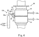
Fig. 4 is a front view of an emergency release system (connected state) of a loading arm according to Example 2. -
Fig. 5 is a front view of the emergency release system (separated state) ofFig. 4 . -
Fig. 6 is an enlarged plan view showing major constituents of acontainer support mechanism 13A ofFigs. 4 and5 -
Fig. 7 is an enlarged front view showing major constituents of a reservoir container according to Example 3. - Hereinafter, Embodiment of the present invention will be described by use of Examples.
- As shown in
Fig. 1 , aloading arm 2 for liquefied hydrogen including a flexible vacuum heat-insulating double pipe (not shown) in an inside thereof is placed on a land, in order to unload the liquefied hydrogen from a liquefied hydrogen tank 1a of a liquefied hydrogen transport marine vessel 1 to a land-based liquefied hydrogen tank (not shown) or to load the liquefied hydrogen from the land-based liquefied hydrogen tank to the liquefied hydrogen transport marine vessel 1. The vacuum heat-insulating double pipe of theloading arm 2 is connected to the liquefied hydrogen tank (not shown) via a land-based liquefied hydrogen pipe. - This
loading arm 2 includes anouter riser 3, an inboard boom 4, and anoutboard boom 5, as an outer tube structure which covers and supports the vacuum heat-insulating double pipe which flows the liquefied hydrogen therethrough. Theloading arm 2 includes an emergency release system 6 (ERS) connected to the vacuum heat-insulating double pipe, and a vacuum heat-insulating double connection pipe 7 connected to theemergency release system 6. - In a case where the liquefied hydrogen is loaded or unloaded via the
loading arm 2, a joint portion at the tip end of the vacuum heat-insulating double connection pipe 7 is connected to ajoint portion 9 of amanifold 8 of a liquefied hydrogen pipe provided on the liquefied hydrogen transport marine vessel 1, and in this state, the liquefied hydrogen is transferred. - If weather gets worse and the liquefied hydrogen transport marine vessel 1 significantly shakes, or an earthquake or tsunami occurs in a state in which the
loading arm 2 is connected to thejoint portion 9 of themanifold 8, theloading arm 2 may be damaged. To avoid this, theloading arm 2 is equipped with the emergency release system 6 (ERS). - Next, the emergency release system 6 (ERS) will be described with reference to
Figs. 2 and3 . - The
emergency release system 6 includes a first shut-offvalve unit 10 which is land-based, and a second shut-offvalve unit 11 which is provided for the marine vessel and separably connected to the first shut-offvalve unit 10. The first shut-offvalve unit 10 is provided with areservoir container 12 which receives liquid air which is generated in a connection opening of the first shut-offvalve unit 10 and dropped, in a state in which the second shut-offvalve unit 11 is separated from the first shut-offvalve unit 10. - The first and second shut-off
valve units valve shafts valve units emergency release system 6 is activated, thevalve shafts valve units loading arm 2 and the liquefied hydrogen tank 1a. - An
electric heater 10b is wound around thevalve shaft 10a of the first shut-off valve of the first shut-offvalve unit 10. In a case where theemergency release system 6 is activated, an electric current is supplied to theelectric heater 10b, to suppress generation of the liquid air in the connection opening of the first shut-offvalve unit 10. It should be noted that theelectric heater 10b is not essential and may be omitted. - The
reservoir container 12 includes atubular member 12a with a short cylinder shape, and aflat bottom member 12b closing the bottom surface of thetubular member 12a. Thereservoir container 12 is automatically shifted from a retracted position to a reserving position by a container support mechanism 13 (described later) in a case where theemergency release system 6 is activated. Thereservoir container 12 is formed of a metal material such as SUS for extremely low temperatures or aluminum. - When the
reservoir container 12 is at the retracted position, thereservoir container 12 is retained in a vertical posture (thebottom member 12b extends vertically) at a lateral position of the first and second shut-offvalve units reservoir container 12 is at the reserving position, thereservoir container 12 is retained in a horizontal posture (thebottom member 12b extends horizontally) at a location that is immediately below the first shut-offvalve unit 10. - During a normal state, namely, in a case where the
emergency release system 6 is not activated, the first and second shut-offvalve units reservoir container 12 is retained at the retracted position. On the other hand, in a case where an unexpected emergency occurs, theemergency release system 6 is activated, the first shut-offvalve unit 10 is disconnected and separated from the second shut-offvalve unit 11, and thereservoir container 12 is automatically moved to the reserving position and retained at the reserving position. - Next, the above-described
container support mechanism 13 will be described with reference toFigs. 2 and3 . Thecontainer support mechanism 13 is configured to support thereservoir container 12 and automatically shift thereservoir container 12 from the retracted position to the reserving position. Thecontainer support mechanism 13 includes a pair oflink members 14 and astay member 15. The pair oflink members 14 and thestay member 15 are formed of a metal material such as SUS or aluminum. - The pair of
link members 14 are configured to couple thereservoir container 12 to the first shut-offvalve unit 10 in such a manner that thereservoir container 12 and the pair oflink members 14 are pivotable. The pair oflink members 14 extend from thebottom member 12b to the first shut-offvalve unit 10 along a direction perpendicular to thebottom member 12b. The first (one) end portions of the pair oflink members 14 are secured to the both side portions, respectively, of thetubular member 12a of thereservoir container 12, by welding. The second (the other) end portions of the pair oflink members 14 are hingedly coupled to the both side portions, respectively, of the first shut-offvalve unit 10, by use of apin member 16. - The
stay member 15 is configured to receive and hold the lower end of thetubular member 12a from below, and retain thereservoir container 12 at the retracted position, when thereservoir container 12 is at the retracted position. Thestay member 15 includes asupport base 15a in a first end portion (upper end portion) thereof. The second end portion (lower end portion) of thestay member 15 is secured to one side portion of the second shut-offvalve unit 11, by welding. - The operation and advantages of the
emergency release system 6 of theloading arm 2 for liquefied hydrogen, configured in the above-described manner, will be described. During the normal state, theemergency release system 6 is not activated, and the first and second shut-offvalve units Fig. 2 , the lower end portion of thetubular member 12a of thereservoir container 12 is received and held by thesupport base 15a of thestay member 15 from below. Therefore, thereservoir container 12 is retained at the retracted position that is the lateral position of the first and second shut-offvalve units - On the other hand, in a case where an unexpected emergency occurs and the
emergency release system 6 is activated, the first and second shut-offvalve units valve unit 10 supported by theloading arm 2 is moved upward, as shown inFig. 3 . Thestay member 15 ceases to retain thereservoir container 12 at the retracted position. Thereservoir container 12 and thecontainer support mechanism 13 are automatically pivoted in a downward direction around thepin member 16, by their own weights. Thereservoir container 12 is moved to the reserving position that is immediately below the first shut-offvalve unit 10 and stopped in the horizontal posture. Since thereservoir container 12 receives the liquid air generated in the first shut-offvalve unit 10 and dropped, it becomes possible to reliably prevent the liquid air from being dropped to sea surface. - The present example incudes a
container support mechanism 13A ofFigs. 4 to 6 , instead of thecontainer support mechanism 13 of the above-described Example 1. The constituents other than thecontainer support mechanism 13A are identical to those of Example 1. Therefore, the same constituents are identified by the same reference symbols and will not be described. - The
container support mechanism 13A includes a L-shapedmember 20, a first end portion of which is secured to thereservoir container 12, a pair ofbrackets 21 attached on the side portions of the first shut-offvalve unit 10, acoupling pin 22 coupling the second end portion of the L-shapedmember 20 to the tip end portions of thebrackets 21, aspring member 23 which is externally mounted on thecoupling pin 22 and configured to bias thereservoir container 12 toward the reserving position, astay member 24 which is secured to the second shut-offvalve unit 11 and configured to receive and hold thereservoir container 12 at the retracted position from below, and astopper 25 which is secured to the first shut-offvalve unit 10 and configured to receive and hold the L-shapedmember 20 and retain thereservoir container 12 at the reserving position, in a state in which the first and second shut-offvalve units - The L-shaped
member 20 includes afirst arm portion 20a and asecond arm portion 20b. The tip end portion of thefirst arm portion 20a is secured to thetubular member 12a of thereservoir container 12, by welding. The end portion of thesecond arm portion 20b is coupled to the pair ofbrackets 21 via thecoupling pin 22 in such a manner that thesecond arm portion 20b is rotatable. As shown inFig. 6 , thespring member 23 is a distortion spring which is sufficiently tightly wound in a clockwise direction. The tip end portion of thespring member 23 is engaged with the upper surface of thesecond arm portion 20b. The base end portion of thespring member 23 is engaged with one of thebrackets 21. Thespring member 23 is configured to bias the L-shapedmember 20 and thereservoir container 12 in a counterclockwise direction inFig. 5 . - As shown in
Fig. 4 , during a normal state, namely, in a case where theemergency release system 6A is not activated, and the first and second shut-offvalve units second arm portion 20b of the L-shapedmember 20 is received and held by the tip end of thestay member 24 from below, and thereservoir container 12 is retained at the retracted position that is the lateral position of the first and second shut-offvalve units reservoir container 12 is retained in the vertical posture in which thebottom member 12b extends vertically. - In a case where an unexpected emergency occurs and the emergency release system is activated, the first and second shut-off
valve units valve unit 10 supported by theloading arm 2 is moved upward. Since thestay member 24 ceases to function, thereservoir container 12 is pivoted in the downward direction around thecoupling pin 22, by an elastic biasing force applied by thespring member 23. - Then, as shown in
Fig. 5 , thereservoir container 12 is moved to the reserving position that is immediately below the first shut-offvalve unit 10, and the inner surface of thesecond arm portion 20b of the L-shapedmember 20 is engaged with the tip end surface of thestopper 25. Therefore, thereservoir container 12 is retained in the horizontal posture at the reserving position. Since thereservoir container 12 can receive the liquid air generated in the connection opening of the first shut-offvalve unit 10 and dropped, it becomes possible to reliably prevent the liquid air from being dropped to sea surface. - The present example includes a
reservoir container 12A ofFig. 7 , instead of thereservoir container 12 of the above-described Example 2. The constituents other than thereservoir container 12A are identical to those of Example 2. Therefore, the same constituents are identified by the same reference symbols and will not be described. - The
reservoir container 12A is provided with a plurality offins 30 protruding from the outer surface of a bottom member 12bA of thereservoir container 12A in such a manner that the plurality offins 30 are integrated with the bottom member 12bA. In a front view, thefins 30 have a tapered shape. In a side view, thefins 30 have a rectangular band shape extending in a forward and rearward direction. The plurality offins 30 are spaced apart from each other with a specified gap and extend in parallel with each other in a rightward and leftward direction. - With the
fins 30, ambient heat can be easily absorbed in thereservoir container 12A, and evaporation of the liquid air generated and received by thereservoir container 12A can be facilitated. The other constituents, operation and advantages are identical to those of Example 2, and therefore will not be described. Alternatively, thefins 30 may be integrated with thebottom member 12b of thereservoir container 12 of Example 1. - Modified examples of the above-described examples will be described.
- 1) The shape of the
reservoir container 12 is not limited to the cylinder, and may be, for example, a rectangular box so long as thereservoir container 12 can reserve the dropped liquid air. - 2) The emergency release system of the loading arm for low-temperature fluids of the present invention is applicable in the same manner to a loading arm which unloads the liquefied hydrogen from a tank lorry to a land-based liquefied hydrogen station.
- 3) Furthermore, those skilled in the art can add a variety of alterations (modifications) to the above-described examples within the scope of the present invention. The present invention encompasses such alterations.
-
- 1
- liquefied hydrogen transport marine vessel
- 2
- loading arm for low-temperature fluids
- 6
- emergency release system
- 10
- first shut-off valve unit
- 10b
- electric heater
- 11
- second shut-off valve unit
- 12
- reservoir container
- 13, 13A
- container support mechanism
- 14
- link member
- 15
- stay member
- 20
- L-shaped member
- 21
- a pair of brackets
- 22
- coupling pin
- 23
- spring member
- 24
- stay member
- 25
- stopper
- 30
- fins
Claims (6)
- An emergency release system equipped in a loading arm for liquefied hydrogen, the emergency release system comprising:a first shut-off valve unit which is land-based; anda second shut-off valve unit which is provided for a marine vessel and separably connected to the first shut-off valve unit,wherein the first shut-off valve unit is provided with a reservoir container which receives liquid air generated in the first shut-off valve unit and dropped, in a state in which the second shut-off valve unit is separated from the first shut-off valve unit.
- The emergency release system for liquefied hydrogen, according to claim 1, further comprising:
a container support mechanism which is capable of retaining the reservoir container at a retracted position that is a lateral position of the first and second shut-off valve units in a state in which the first and second shut-off valve units are connected to each other, the container support mechanism being configured to automatically shift the reservoir container to a reserving position that is immediately below the first shut-off valve unit, in a state in which the first and second shut-off valve units are separated from each other. - The emergency release system for liquefied hydrogen, according to claim 2,
wherein the reservoir container is retained in a horizontal posture at the reserving position,
wherein the reservoir container is retained in a vertical posture at the retracted position, and
wherein the container support mechanism includes:a pair of link members, first end portions of which are secured to both side portions, respectively, of the reservoir container, and second end portions of which are hingedly coupled to both side portions, respectively, of the first shut-off valve unit, the pair of link members extending from the reservoir container to the first shut-off valve unit, anda stay member which is secured to the second shut-off valve unit and configured to receive and hold the reservoir container at the retracted position from below. - The emergency release system for liquefied hydrogen, according to claim 2,
wherein the reservoir container is retained in a horizontal posture at the reserving position,
wherein the reservoir container is retained in a vertical posture at the retracted position, and
wherein the container support mechanism includes:a L-shaped member, a first end portion of which is secured to a side portion of the reservoir container,a pair of brackets attached on side portions of the first shut-off valve unit,a coupling pin coupling a second end portion of the L-shaped member to tip end portions of the brackets,a spring member which is externally mounted on the coupling pin and configured to bias the reservoir container toward the reserving position,a stay member which is secured to the second shut-off valve unit and configured to receive and hold the reservoir container at the retracted position from below, anda stopper which is secured to the first shut-off valve unit and configured to receive and hold the L-shaped member and retain the reservoir container at the reserving position, in a state in which the first and second shut-off valve units are separated from each other. - The emergency release system for liquefied hydrogen, according to any one of claims 1 to 4,
wherein the reservoir container is provided with a plurality of fins protruding from an outer surface of the reservoir container in such a manner that the plurality of fins are integrated with the reservoir container. - The emergency release system for liquefied hydrogen, according to any one of claims 1 to 4,
wherein an electric heater is attached on a valve shaft of a shut-off valve of the first shut-off valve unit.
Applications Claiming Priority (2)
| Application Number | Priority Date | Filing Date | Title |
|---|---|---|---|
| JP2015140269A JP6571425B2 (en) | 2015-07-14 | 2015-07-14 | Emergency separation system for liquid hydrogen |
| PCT/JP2016/003284 WO2017010082A1 (en) | 2015-07-14 | 2016-07-11 | Emergency detachment system for liquefied hydrogen |
Publications (3)
| Publication Number | Publication Date |
|---|---|
| EP3323776A1 true EP3323776A1 (en) | 2018-05-23 |
| EP3323776A4 EP3323776A4 (en) | 2019-03-06 |
| EP3323776B1 EP3323776B1 (en) | 2020-07-01 |
Family
ID=57756975
Family Applications (1)
| Application Number | Title | Priority Date | Filing Date |
|---|---|---|---|
| EP16824067.9A Active EP3323776B1 (en) | 2015-07-14 | 2016-07-11 | Emergency detachment system for liquefied hydrogen |
Country Status (5)
| Country | Link |
|---|---|
| US (1) | US10724688B2 (en) |
| EP (1) | EP3323776B1 (en) |
| JP (1) | JP6571425B2 (en) |
| CN (1) | CN107835787B (en) |
| WO (1) | WO2017010082A1 (en) |
Families Citing this family (2)
| Publication number | Priority date | Publication date | Assignee | Title |
|---|---|---|---|---|
| JP7229050B2 (en) * | 2019-03-14 | 2023-02-27 | 大阪瓦斯株式会社 | Equipment for handling liquefied cryogenic fluids |
| JP7579702B2 (en) * | 2020-12-25 | 2024-11-08 | 川崎重工業株式会社 | Portable loading and unloading equipment for liquid hydrogen |
Family Cites Families (13)
| Publication number | Priority date | Publication date | Assignee | Title |
|---|---|---|---|---|
| DE2108538A1 (en) * | 1971-02-23 | 1972-09-14 | Amrogowicz E | Inlet or outlet connection with sealing cap |
| DE2717135C3 (en) * | 1977-04-19 | 1985-07-18 | Wiese, Knut, 4600 Dortmund | Device for separating a liquid line with a large cross-section |
| JPS5879600U (en) * | 1981-11-27 | 1983-05-30 | 三菱重工業株式会社 | Base quay fluid transfer device |
| JPS59163295U (en) * | 1983-04-18 | 1984-11-01 | 三井造船株式会社 | Drip pan with drainage device |
| JPS59224715A (en) * | 1983-06-02 | 1984-12-17 | Mitsubishi Heavy Ind Ltd | Preventer for diffusion of liquefied gas |
| JPS62189998U (en) * | 1986-05-27 | 1987-12-03 | ||
| US5181750A (en) * | 1990-08-09 | 1993-01-26 | Avon Plastics, Inc. | Garden hose and couplings |
| JPH0694177A (en) * | 1992-09-09 | 1994-04-05 | Fujitsu Ltd | Coupler mounting construction |
| US5915410A (en) * | 1996-02-01 | 1999-06-29 | Zajac; John | Pneumatically operated positive shutoff throttle valve |
| JP3517146B2 (en) * | 1999-02-25 | 2004-04-05 | ニイガタ・ローディング・システムズ株式会社 | Oil splattering prevention device for loading arm |
| CN2515185Y (en) * | 2001-11-22 | 2002-10-09 | 连云港远洋流体装卸设备有限公司 | Wharf liquid loading and unloading arm emergency release device |
| DE102012103061A1 (en) * | 2012-03-23 | 2013-09-26 | Andreas von Keitz | Coupling for connecting fluid-carrying lines |
| CN103090181B (en) * | 2013-02-04 | 2015-04-22 | 连云港远洋流体装卸设备有限公司 | Ship-use low-temperature fluid loading and unloading device |
-
2015
- 2015-07-14 JP JP2015140269A patent/JP6571425B2/en active Active
-
2016
- 2016-07-11 CN CN201680035902.6A patent/CN107835787B/en active Active
- 2016-07-11 US US15/743,306 patent/US10724688B2/en active Active
- 2016-07-11 EP EP16824067.9A patent/EP3323776B1/en active Active
- 2016-07-11 WO PCT/JP2016/003284 patent/WO2017010082A1/en not_active Ceased
Also Published As
| Publication number | Publication date |
|---|---|
| EP3323776A4 (en) | 2019-03-06 |
| US10724688B2 (en) | 2020-07-28 |
| EP3323776B1 (en) | 2020-07-01 |
| US20180195671A1 (en) | 2018-07-12 |
| CN107835787B (en) | 2019-11-08 |
| JP6571425B2 (en) | 2019-09-04 |
| CN107835787A (en) | 2018-03-23 |
| WO2017010082A1 (en) | 2017-01-19 |
| JP2017019543A (en) | 2017-01-26 |
Similar Documents
| Publication | Publication Date | Title |
|---|---|---|
| JP6545023B2 (en) | Liquid hydrogen loading arm and liquid hydrogen transfer method | |
| AU2015325623B2 (en) | Liquefied hydrogen transport system | |
| US11878774B2 (en) | Tie-in system and fluid transfer system comprising such a tie-in system | |
| CN101646597A (en) | System for transferring fluids between floating vessels using flexible conduit and releasable mooring system | |
| EP3323776B1 (en) | Emergency detachment system for liquefied hydrogen | |
| EP3321552B1 (en) | Emergency release device for fluid loading/unloading apparatus | |
| JP7574077B2 (en) | Ships | |
| KR102662432B1 (en) | Apparatus for transferring liquid cargo | |
| KR20100123982A (en) | Apparatus for collecting leakage of an independence type storage tank | |
| EP3286133A1 (en) | Deployable connection and emergency release system | |
| WO2009068768A1 (en) | Apparatus for transferring a fluid between a first ship and a second ship floating on an expanse of water, and related transport assembly and method | |
| JP7580236B2 (en) | Emergency release mechanism for fluid handling equipment | |
| KR20110000877U (en) | Apparatus for collecting leakage of an independence type storage tank | |
| Hodgson et al. | LNG as a fuel for offshore vessels-Bunkering technology | |
| KR20110012219A (en) | Marine Fire Protection Equipment | |
| KR101498245B1 (en) | Liquid cargo handling apparatus and ship having the same | |
| ES3005383T3 (en) | Support vessel for assisting in loading fluid hydrocarbon cargo onto a carrier vessel, and related system and method | |
| KR100929709B1 (en) | Liquefied Natural Gas Transfer System for Floating Natural Gas Storage Ship | |
| KR101216039B1 (en) | Liquid cargo load and unload apparatus | |
| KR20230101273A (en) | Hull protection system of floating marine structure | |
| JP2011207487A (en) | Valve with erroneous operation preventing function, loading arm, and method for preventing erroneous operation of valve |
Legal Events
| Date | Code | Title | Description |
|---|---|---|---|
| STAA | Information on the status of an ep patent application or granted ep patent |
Free format text: STATUS: THE INTERNATIONAL PUBLICATION HAS BEEN MADE |
|
| PUAI | Public reference made under article 153(3) epc to a published international application that has entered the european phase |
Free format text: ORIGINAL CODE: 0009012 |
|
| STAA | Information on the status of an ep patent application or granted ep patent |
Free format text: STATUS: REQUEST FOR EXAMINATION WAS MADE |
|
| 17P | Request for examination filed |
Effective date: 20180118 |
|
| AK | Designated contracting states |
Kind code of ref document: A1 Designated state(s): AL AT BE BG CH CY CZ DE DK EE ES FI FR GB GR HR HU IE IS IT LI LT LU LV MC MK MT NL NO PL PT RO RS SE SI SK SM TR |
|
| AX | Request for extension of the european patent |
Extension state: BA ME |
|
| DAV | Request for validation of the european patent (deleted) | ||
| DAX | Request for extension of the european patent (deleted) | ||
| A4 | Supplementary search report drawn up and despatched |
Effective date: 20190205 |
|
| RIC1 | Information provided on ipc code assigned before grant |
Ipc: F17C 13/12 20060101ALI20190130BHEP Ipc: B63B 27/24 20060101ALI20190130BHEP Ipc: B67D 9/02 20100101AFI20190130BHEP |
|
| RAP1 | Party data changed (applicant data changed or rights of an application transferred) |
Owner name: KAWASAKI JUKOGYO KABUSHIKI KAISHA Owner name: TOKYO BOEKI ENGINEERING LTD. |
|
| GRAP | Despatch of communication of intention to grant a patent |
Free format text: ORIGINAL CODE: EPIDOSNIGR1 |
|
| STAA | Information on the status of an ep patent application or granted ep patent |
Free format text: STATUS: GRANT OF PATENT IS INTENDED |
|
| INTG | Intention to grant announced |
Effective date: 20200117 |
|
| GRAS | Grant fee paid |
Free format text: ORIGINAL CODE: EPIDOSNIGR3 |
|
| GRAA | (expected) grant |
Free format text: ORIGINAL CODE: 0009210 |
|
| STAA | Information on the status of an ep patent application or granted ep patent |
Free format text: STATUS: THE PATENT HAS BEEN GRANTED |
|
| AK | Designated contracting states |
Kind code of ref document: B1 Designated state(s): AL AT BE BG CH CY CZ DE DK EE ES FI FR GB GR HR HU IE IS IT LI LT LU LV MC MK MT NL NO PL PT RO RS SE SI SK SM TR |
|
| REG | Reference to a national code |
Ref country code: CH Ref legal event code: EP Ref country code: AT Ref legal event code: REF Ref document number: 1286023 Country of ref document: AT Kind code of ref document: T Effective date: 20200715 |
|
| REG | Reference to a national code |
Ref country code: IE Ref legal event code: FG4D |
|
| REG | Reference to a national code |
Ref country code: DE Ref legal event code: R096 Ref document number: 602016039246 Country of ref document: DE |
|
| REG | Reference to a national code |
Ref country code: LT Ref legal event code: MG4D |
|
| PG25 | Lapsed in a contracting state [announced via postgrant information from national office to epo] |
Ref country code: BG Free format text: LAPSE BECAUSE OF FAILURE TO SUBMIT A TRANSLATION OF THE DESCRIPTION OR TO PAY THE FEE WITHIN THE PRESCRIBED TIME-LIMIT Effective date: 20201001 |
|
| REG | Reference to a national code |
Ref country code: NL Ref legal event code: MP Effective date: 20200701 |
|
| REG | Reference to a national code |
Ref country code: AT Ref legal event code: MK05 Ref document number: 1286023 Country of ref document: AT Kind code of ref document: T Effective date: 20200701 |
|
| PG25 | Lapsed in a contracting state [announced via postgrant information from national office to epo] |
Ref country code: FI Free format text: LAPSE BECAUSE OF FAILURE TO SUBMIT A TRANSLATION OF THE DESCRIPTION OR TO PAY THE FEE WITHIN THE PRESCRIBED TIME-LIMIT Effective date: 20200701 Ref country code: HR Free format text: LAPSE BECAUSE OF FAILURE TO SUBMIT A TRANSLATION OF THE DESCRIPTION OR TO PAY THE FEE WITHIN THE PRESCRIBED TIME-LIMIT Effective date: 20200701 Ref country code: SE Free format text: LAPSE BECAUSE OF FAILURE TO SUBMIT A TRANSLATION OF THE DESCRIPTION OR TO PAY THE FEE WITHIN THE PRESCRIBED TIME-LIMIT Effective date: 20200701 Ref country code: ES Free format text: LAPSE BECAUSE OF FAILURE TO SUBMIT A TRANSLATION OF THE DESCRIPTION OR TO PAY THE FEE WITHIN THE PRESCRIBED TIME-LIMIT Effective date: 20200701 Ref country code: NO Free format text: LAPSE BECAUSE OF FAILURE TO SUBMIT A TRANSLATION OF THE DESCRIPTION OR TO PAY THE FEE WITHIN THE PRESCRIBED TIME-LIMIT Effective date: 20201001 Ref country code: GR Free format text: LAPSE BECAUSE OF FAILURE TO SUBMIT A TRANSLATION OF THE DESCRIPTION OR TO PAY THE FEE WITHIN THE PRESCRIBED TIME-LIMIT Effective date: 20201002 Ref country code: LT Free format text: LAPSE BECAUSE OF FAILURE TO SUBMIT A TRANSLATION OF THE DESCRIPTION OR TO PAY THE FEE WITHIN THE PRESCRIBED TIME-LIMIT Effective date: 20200701 Ref country code: PT Free format text: LAPSE BECAUSE OF FAILURE TO SUBMIT A TRANSLATION OF THE DESCRIPTION OR TO PAY THE FEE WITHIN THE PRESCRIBED TIME-LIMIT Effective date: 20201102 Ref country code: CZ Free format text: LAPSE BECAUSE OF FAILURE TO SUBMIT A TRANSLATION OF THE DESCRIPTION OR TO PAY THE FEE WITHIN THE PRESCRIBED TIME-LIMIT Effective date: 20200701 Ref country code: AT Free format text: LAPSE BECAUSE OF FAILURE TO SUBMIT A TRANSLATION OF THE DESCRIPTION OR TO PAY THE FEE WITHIN THE PRESCRIBED TIME-LIMIT Effective date: 20200701 |
|
| PG25 | Lapsed in a contracting state [announced via postgrant information from national office to epo] |
Ref country code: PL Free format text: LAPSE BECAUSE OF FAILURE TO SUBMIT A TRANSLATION OF THE DESCRIPTION OR TO PAY THE FEE WITHIN THE PRESCRIBED TIME-LIMIT Effective date: 20200701 Ref country code: LV Free format text: LAPSE BECAUSE OF FAILURE TO SUBMIT A TRANSLATION OF THE DESCRIPTION OR TO PAY THE FEE WITHIN THE PRESCRIBED TIME-LIMIT Effective date: 20200701 Ref country code: RS Free format text: LAPSE BECAUSE OF FAILURE TO SUBMIT A TRANSLATION OF THE DESCRIPTION OR TO PAY THE FEE WITHIN THE PRESCRIBED TIME-LIMIT Effective date: 20200701 Ref country code: IS Free format text: LAPSE BECAUSE OF FAILURE TO SUBMIT A TRANSLATION OF THE DESCRIPTION OR TO PAY THE FEE WITHIN THE PRESCRIBED TIME-LIMIT Effective date: 20201101 |
|
| REG | Reference to a national code |
Ref country code: CH Ref legal event code: PL |
|
| PG25 | Lapsed in a contracting state [announced via postgrant information from national office to epo] |
Ref country code: MC Free format text: LAPSE BECAUSE OF FAILURE TO SUBMIT A TRANSLATION OF THE DESCRIPTION OR TO PAY THE FEE WITHIN THE PRESCRIBED TIME-LIMIT Effective date: 20200701 Ref country code: NL Free format text: LAPSE BECAUSE OF FAILURE TO SUBMIT A TRANSLATION OF THE DESCRIPTION OR TO PAY THE FEE WITHIN THE PRESCRIBED TIME-LIMIT Effective date: 20200701 |
|
| REG | Reference to a national code |
Ref country code: DE Ref legal event code: R097 Ref document number: 602016039246 Country of ref document: DE |
|
| REG | Reference to a national code |
Ref country code: BE Ref legal event code: MM Effective date: 20200731 |
|
| PG25 | Lapsed in a contracting state [announced via postgrant information from national office to epo] |
Ref country code: LI Free format text: LAPSE BECAUSE OF NON-PAYMENT OF DUE FEES Effective date: 20200731 Ref country code: LU Free format text: LAPSE BECAUSE OF NON-PAYMENT OF DUE FEES Effective date: 20200711 Ref country code: CH Free format text: LAPSE BECAUSE OF NON-PAYMENT OF DUE FEES Effective date: 20200731 Ref country code: DK Free format text: LAPSE BECAUSE OF FAILURE TO SUBMIT A TRANSLATION OF THE DESCRIPTION OR TO PAY THE FEE WITHIN THE PRESCRIBED TIME-LIMIT Effective date: 20200701 Ref country code: RO Free format text: LAPSE BECAUSE OF FAILURE TO SUBMIT A TRANSLATION OF THE DESCRIPTION OR TO PAY THE FEE WITHIN THE PRESCRIBED TIME-LIMIT Effective date: 20200701 Ref country code: EE Free format text: LAPSE BECAUSE OF FAILURE TO SUBMIT A TRANSLATION OF THE DESCRIPTION OR TO PAY THE FEE WITHIN THE PRESCRIBED TIME-LIMIT Effective date: 20200701 Ref country code: SM Free format text: LAPSE BECAUSE OF FAILURE TO SUBMIT A TRANSLATION OF THE DESCRIPTION OR TO PAY THE FEE WITHIN THE PRESCRIBED TIME-LIMIT Effective date: 20200701 |
|
| PLBE | No opposition filed within time limit |
Free format text: ORIGINAL CODE: 0009261 |
|
| STAA | Information on the status of an ep patent application or granted ep patent |
Free format text: STATUS: NO OPPOSITION FILED WITHIN TIME LIMIT |
|
| PG25 | Lapsed in a contracting state [announced via postgrant information from national office to epo] |
Ref country code: BE Free format text: LAPSE BECAUSE OF NON-PAYMENT OF DUE FEES Effective date: 20200731 Ref country code: AL Free format text: LAPSE BECAUSE OF FAILURE TO SUBMIT A TRANSLATION OF THE DESCRIPTION OR TO PAY THE FEE WITHIN THE PRESCRIBED TIME-LIMIT Effective date: 20200701 |
|
| 26N | No opposition filed |
Effective date: 20210406 |
|
| GBPC | Gb: european patent ceased through non-payment of renewal fee |
Effective date: 20201001 |
|
| PG25 | Lapsed in a contracting state [announced via postgrant information from national office to epo] |
Ref country code: SK Free format text: LAPSE BECAUSE OF FAILURE TO SUBMIT A TRANSLATION OF THE DESCRIPTION OR TO PAY THE FEE WITHIN THE PRESCRIBED TIME-LIMIT Effective date: 20200701 |
|
| PG25 | Lapsed in a contracting state [announced via postgrant information from national office to epo] |
Ref country code: SI Free format text: LAPSE BECAUSE OF FAILURE TO SUBMIT A TRANSLATION OF THE DESCRIPTION OR TO PAY THE FEE WITHIN THE PRESCRIBED TIME-LIMIT Effective date: 20200701 Ref country code: GB Free format text: LAPSE BECAUSE OF NON-PAYMENT OF DUE FEES Effective date: 20201001 Ref country code: IE Free format text: LAPSE BECAUSE OF NON-PAYMENT OF DUE FEES Effective date: 20200711 |
|
| REG | Reference to a national code |
Ref country code: DE Ref legal event code: R081 Ref document number: 602016039246 Country of ref document: DE Owner name: TB GLOBAL TECHNOLOGIES LTD., JP Free format text: FORMER OWNERS: KAWASAKI JUKOGYO KABUSHIKI KAISHA, KOBE-SHI, HYOGO, JP; TOKYO BOEKI ENGINEERING LTD., TOKYO, JP Ref country code: DE Ref legal event code: R081 Ref document number: 602016039246 Country of ref document: DE Owner name: KAWASAKI JUKOGYO KABUSHIKI KAISHA, KOBE-SHI, JP Free format text: FORMER OWNERS: KAWASAKI JUKOGYO KABUSHIKI KAISHA, KOBE-SHI, HYOGO, JP; TOKYO BOEKI ENGINEERING LTD., TOKYO, JP |
|
| PG25 | Lapsed in a contracting state [announced via postgrant information from national office to epo] |
Ref country code: TR Free format text: LAPSE BECAUSE OF FAILURE TO SUBMIT A TRANSLATION OF THE DESCRIPTION OR TO PAY THE FEE WITHIN THE PRESCRIBED TIME-LIMIT Effective date: 20200701 Ref country code: MT Free format text: LAPSE BECAUSE OF FAILURE TO SUBMIT A TRANSLATION OF THE DESCRIPTION OR TO PAY THE FEE WITHIN THE PRESCRIBED TIME-LIMIT Effective date: 20200701 Ref country code: CY Free format text: LAPSE BECAUSE OF FAILURE TO SUBMIT A TRANSLATION OF THE DESCRIPTION OR TO PAY THE FEE WITHIN THE PRESCRIBED TIME-LIMIT Effective date: 20200701 |
|
| PG25 | Lapsed in a contracting state [announced via postgrant information from national office to epo] |
Ref country code: MK Free format text: LAPSE BECAUSE OF FAILURE TO SUBMIT A TRANSLATION OF THE DESCRIPTION OR TO PAY THE FEE WITHIN THE PRESCRIBED TIME-LIMIT Effective date: 20200701 |
|
| PGFP | Annual fee paid to national office [announced via postgrant information from national office to epo] |
Ref country code: DE Payment date: 20250528 Year of fee payment: 10 |
|
| PGFP | Annual fee paid to national office [announced via postgrant information from national office to epo] |
Ref country code: IT Payment date: 20260622 Year of fee payment: 11 |
|
| PGFP | Annual fee paid to national office [announced via postgrant information from national office to epo] |
Ref country code: FR Payment date: 20260608 Year of fee payment: 11 |