EP3323757B1 - Waste managing assembly - Google Patents
Waste managing assembly Download PDFInfo
- Publication number
- EP3323757B1 EP3323757B1 EP17202541.3A EP17202541A EP3323757B1 EP 3323757 B1 EP3323757 B1 EP 3323757B1 EP 17202541 A EP17202541 A EP 17202541A EP 3323757 B1 EP3323757 B1 EP 3323757B1
- Authority
- EP
- European Patent Office
- Prior art keywords
- waste
- tank section
- discharge
- receiving tank
- storage
- Prior art date
- Legal status (The legal status is an assumption and is not a legal conclusion. Google has not performed a legal analysis and makes no representation as to the accuracy of the status listed.)
- Not-in-force
Links
Images


Classifications
-
- B—PERFORMING OPERATIONS; TRANSPORTING
- B65—CONVEYING; PACKING; STORING; HANDLING THIN OR FILAMENTARY MATERIAL
- B65F—GATHERING OR REMOVAL OF DOMESTIC OR LIKE REFUSE
- B65F1/00—Refuse receptacles; Accessories therefor
- B65F1/12—Refuse receptacles; Accessories therefor with devices facilitating emptying
- B65F1/125—Features allowing the receptacle to be lifted and emptied by its bottom
-
- B—PERFORMING OPERATIONS; TRANSPORTING
- B65—CONVEYING; PACKING; STORING; HANDLING THIN OR FILAMENTARY MATERIAL
- B65D—CONTAINERS FOR STORAGE OR TRANSPORT OF ARTICLES OR MATERIALS, e.g. BAGS, BARRELS, BOTTLES, BOXES, CANS, CARTONS, CRATES, DRUMS, JARS, TANKS, HOPPERS, FORWARDING CONTAINERS; ACCESSORIES, CLOSURES, OR FITTINGS THEREFOR; PACKAGING ELEMENTS; PACKAGES
- B65D90/00—Component parts, details or accessories for large containers
- B65D90/54—Gates or closures
- B65D90/58—Gates or closures having closure members sliding in the plane of the opening
-
- B—PERFORMING OPERATIONS; TRANSPORTING
- B65—CONVEYING; PACKING; STORING; HANDLING THIN OR FILAMENTARY MATERIAL
- B65D—CONTAINERS FOR STORAGE OR TRANSPORT OF ARTICLES OR MATERIALS, e.g. BAGS, BARRELS, BOTTLES, BOXES, CANS, CARTONS, CRATES, DRUMS, JARS, TANKS, HOPPERS, FORWARDING CONTAINERS; ACCESSORIES, CLOSURES, OR FITTINGS THEREFOR; PACKAGING ELEMENTS; PACKAGES
- B65D90/00—Component parts, details or accessories for large containers
- B65D90/54—Gates or closures
- B65D90/66—Operating devices therefor
-
- B—PERFORMING OPERATIONS; TRANSPORTING
- B65—CONVEYING; PACKING; STORING; HANDLING THIN OR FILAMENTARY MATERIAL
- B65F—GATHERING OR REMOVAL OF DOMESTIC OR LIKE REFUSE
- B65F5/00—Gathering or removal of refuse otherwise than by receptacles or vehicles
- B65F5/005—Gathering or removal of refuse otherwise than by receptacles or vehicles by pneumatic means, e.g. by suction
-
- B—PERFORMING OPERATIONS; TRANSPORTING
- B65—CONVEYING; PACKING; STORING; HANDLING THIN OR FILAMENTARY MATERIAL
- B65F—GATHERING OR REMOVAL OF DOMESTIC OR LIKE REFUSE
- B65F2210/00—Equipment of refuse receptacles
- B65F2210/168—Sensing means
Definitions
- the present invention relates to a waste managing assembly for the collection, temporary storage and discharge of waste of various kinds in association with a pneumatic material collection and transport system, according to the preamble of claim 1.
- Vacuum operated waste collection systems are presently used in many parts of the world and are employed for managing different fractions of waste and refuse.
- waste has traditionally been introduced into the system at fixed insertion points.
- said insertion points have some type of integrated temporary waste storage facility in order to provide better waste discharge control.
- the insertion points or their temporary waste storage facilities are connected through a waste transport pipe system to a stationary central waste collection facility with a likewise stationary vacuum source.
- a development of the above briefly described "stationary type” vacuum operated waste collection system involves the use of movable vacuum sources mounted on trucks having a waste tank of considerable volume.
- the vacuum pressure generated by the movable vacuum sources is selectively connected to docking points positioned in the vicinity of one or more temporary waste storage tanks.
- the tank or tanks are in turn connected through discharge pipes to associated docking points and a major advantage of these "mobile type” vacuum operated waste collection systems is that they do not require any extended transport pipe systems connecting insertion points or their temporary waste storage facilities with the central waste collection facility.
- US 4 768 670 A discloses a waste managing assembly according to the preamble of claim 1, comprising a combined dump container consisting of an upper minor garbage collection container and a lower major dump container.
- the minor garbage collection container has a bottom with an automatically operated discharge outlet consisting of a double-layer cover with two mutually slidable cover parts.
- the discharge outlet is opened by the interaction of spring actuated push rods of said discharge outlet with V-shaped troughs at raised walls serving as an interface for docking the minor garbage collection container with the major dump container.
- the present invention provides a waste managing assembly according to claim 1 for the collection, storage and discharge of waste in association with a pneumatic material collection and transport system.
- the waste managing assembly comprises a waste tank and the pneumatic material collection and transport system (100) uses air flow through a pipe to transport collected material from the waste tank at one or more waste deposit and discharge points of the system.
- the waste tank includes a bottom waste storage and discharge tank section for supporting the waste managing assembly at a waste deposit and discharge point; a relocatable top waste receiving tank section having at least one waste introduction opening for introducing waste into the top waste receiving tank section; an interface for docking a lower part of the top waste receiving tank section on an open upper part of the bottom waste storage and discharge tank section; and bottom walls at the lower part of the top waste receiving tank section and operable to open and close communication of waste between the top and bottom tank sections of the waste managing assembly.
- arcuate guide grooves are formed in associated end walls of the top waste receiving tank section, the bottom walls at the lower part of each top waste receiving tank section are swingably and slidably supported in the guide grooves in the opposite end walls of each top waste receiving tank section and are provided with guide members that extend externally of the associated end wall and cooperate with a first pair of guide formations of the interface as well as with said guide grooves to control operation of the bottom walls between a closed position blocking open waste communication between the top waste receiving tank section and the bottom tank section and a position opening communication between a top waste receiving tank section and the bottom waste storage and discharge tank section.
- the present invention now suggests a novel approach for optimizing the versatility of a pneumatic waste material collection and transport system.
- a waste managing assembly for independent collection and temporary storage and then discharge of waste in association with a pneumatic material collection and transport system.
- the waste managing assembly proposed by the present technology may also be defined as a composite waste material container or tank including mutually docking upper and lower container/tank sections. Thereby it enables the use of a quite unique two-stage waste collection approach where the two tank sections may be located at separate appropriate locations and may at intervals be docked for waste discharge.
- the tank/container will throughout the rest of the specification be referred to as a tank, but it will be clear that it may take the form of any appropriate container. It is preferably a so called screw tank type having a feed screw provided adjacent a bottom section of the tank for enabling quick and secure waste discharge from the assembly.
- a bottom discharge tank section with an optional number of separate relocatable top waste receiving temporary storage tank sections said assembly enables optimized and problem-free collection of waste from several locations. With the invention this is in essence achieved by decentralizing the collection of larger amounts of waste without requiring any additional fixed or stationary installations, apart from the single bottom assembly tank section.
- This unique design of the proposed configuration provides several essential advantages that will especially present solutions to problems existing in areas such as in the hospital sector, by commercial properties, larger construction sites etc.
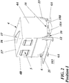
- Fig. 1 illustrates an exemplary embodiment of the waste managing assembly 1.
- the waste managing assembly 1 is intended for the collection, temporary storage and discharge of waste in association with pneumatic material collection and transport systems 100. Such systems use air flow through a waste transport pipe 101 to transport collected waste material from a waste tank 2, 4 at one or more waste deposit and discharge points 102 of the pneumatic material collection and transport system.
- the waste tank 2, 4 of each waste managing assembly 1 basically includes a bottom waste storage and discharge tank section 2 and at least one relocatable top waste receiving tank section 4 associated therewith. In embodiments where the assembly 1 includes more than one top waste receiving tank section 4 these are, apart from being relocatable, also mutually exchangeable, meaning that they may all be connected to the same or to different bottom waste storage and discharge tank sections 2.
- the bottom waste storage and discharge tank section 2 is stationary at a designated waste deposit and discharge point 102 of the pneumatic material collection and transport system 100.
- one or more relocatable top waste receiving tank sections 4 may be associated with each stationary bottom waste storage and discharge tank section 2 and may be located at a designated, later described waste introduction point 103 for receiving waste.
- the bottom waste storage and discharge tank section 2 has a base 3 with a number of support legs 3A for supporting the bottom waste storage and discharge tank section 2 at a waste deposit and discharge point 102 from where collected waste is discharged by vacuum pressure to any type of waste collection facility, such as a stationary type central storage or a mobile type storage (not specifically shown).
- the relocatable top waste receiving tank section 4 has at least one waste introduction opening 5 for introducing waste into said top waste receiving tank section at appropriate waste introduction points or waste receiving locations 103 of a waste collection application. At the side or sides thereof that contain the at least one waste introduction opening 5 the top waste receiving tank section 4 is also preferably provided with a step or platform 25 for facilitating the introduction of waste.
- the top waste receiving tank section 4 also has a base 6 including a number of support legs 6A for independent placement thereof at a waste introduction point 103 where waste is to be introduced into it.
- the support legs 6A are separated so as to be positioned outside a later described interface 7 as well as outside the bottom waste storage and discharge tank section 2 when docking the lower part 10 of the top waste receiving tank section 4 on the open upper part 9 of the bottom waste storage and discharge tank section 2.
- the top waste receiving tank section 4 may be lowered onto and lifted from the bottom waste storage and discharge tank section 2 by means of a truck mounted crane (not specifically shown) or other lifting equipment that is hooked to a lifting eye 17 in a lifting beam 16 provided on an upper part of the top waste receiving tank section 4.
- the bottom waste storage and discharge tank section 2 of the waste tank 2, 4 is located at its designated waste deposit and discharge point 102 and the top waste receiving tank section 4 is relocatable between waste introduction points 103 and a waste deposit and discharge point 102.
- the bottom waste storage and discharge tank section 2 has the above briefly mentioned open upper part 9 and an interface 7 for docking a lower part 10 of the top waste receiving tank section 4 on said open upper part 9 of the bottom waste storage and discharge tank section 2.
- Bottom walls 11A, 11B are provided at the lower part 10 of the top waste receiving tank section 4 and are operable to selectively open and close communication of waste between said top and bottom tank sections 4 and 2, respectively, of the waste managing assembly 1.
- the bottom walls 11A, 11B are movably supported in opposite end walls 4A, 4B of the top waste receiving tank section 4 and are extended along opposite sides of said lower part 10 thereof.
- the bottom walls 11A, 11B are each associated with a support assembly 18 that in cooperation with the interface 7 automatically initiates a swinging-sliding movement of the bottom walls 11A, 11B between open and closed positions II and I, respectively.
- This automatic opening and closing movement of the bottom walls 11A, 11B is caused by interactive cooperation of parts of the bottom wall 11A, 11B support assemblies 18 and the interface 7 as the top waste receiving tank section 4 is lowered onto and lifted from, respectively, the bottom waste storage and discharge tank section 2, as will be described in detail below.
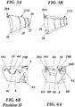
- the interface 7 includes a docking adapter 8 (see Figs 6A-6B ) fixed to the open upper part 9 of the bottom waste storage and discharge tank section 2.
- the docking adapter 8 has first 8A, 8B and second 8D, 8E pairs of guide formations controlling operation of the bottom walls 11A, 11B at the top waste receiving tank section 4 between open II and closed I positions and back.
- the bottom walls 11A, 11B of the top waste receiving tank section 4 are swingably-slidably supported in opposite end walls 4A, 4B of the top waste receiving tank section 4.
- guide members 20A, 20B of the support assemblies 18 In the respective end faces of the bottom walls 11A, 11B are provided guide members 20A, 20B of the support assemblies 18.
- the guide members 20A, 20B extend from the respective end faces of the bottom walls 11A, 11B, through arcuate guide grooves 12, 13 formed in associated end walls 4A, 4B of the top waste receiving tank section 4.
- the guide members 20A, 20B cooperate with a first pair 8A, 8B of docking adapter 8 guide formations as well as with said guide grooves 12, 13 to control bottom wall 11A, 11B operation.
- This operation of the bottom walls 11A, 11B involves their movement between the closed position I blocking an otherwise open waste communication between the top waste receiving tank section 4 and the bottom waste storage and discharge tank section 2 and the open emptying position II opening said communication.
- the bottom walls 11A, 11B are thus guided in the guide grooves 12, 13 in the swinging-sliding movement between the open II and closed I positions.
- the guide grooves 12, 13 each accommodate a guide member 20A, 20B of the bottom walls 11A, 11B for guiding their swinging and sliding movement between the closed waste blocking position I and the open emptying position II.
- a guide block 26 at the end faces thereof, spaced from the associated guide member 20A, 20B, as well as a distributed set of slide rails 27.
- Said slide rails 27 are secured to an outer, curved side of the bottom walls 11A, 11B, facing a side wall of the top waste receiving tank section 4.
- the support assemblies 18 further include a pair of locking arms 18A, 18B (see especially Fig. 4 ) that are pivotally supported in the end walls 4A, 4B.
- the locking arms 18A, 18B are provided with a hook-shaped outer free end that in the closed position I of the bottom walls 11A, 11B is pivoted down to grip a free end of an associated guide member 20A, 20B. This serves to maintain the bottom walls 11A, 11B in a closed and locked position I blocking waste communication between the lower part 10 of the top waste receiving tank section 4 and the bottom waste storage and discharge tank section 2.
- each locking arm 18A, 18B Adjacent the hook-shaped outer free end each locking arm 18A, 18B carries a guide pin 19A, 19B that in use cooperates with an associated one of a pair of second guide formations 8D, 8E formed by opposite sides of a cutout 8C in a middle part of the docking adapter 8.
- said guide pins 19A, 19B cooperate with the associated pair of second guide formations 8D, 8E to lift the hook-shaped free outer ends of the locking arms 18A, 18B from the guide members 20A, 20B.
- the docking adapter 8 also has a pair of first guide formations 8A, 8B in the shape of grooves 8A and 8B that extend at an angle from an open end at a top edge of the docking adapter 8 and to a closed end adjacent a respective side edge thereof.
- Said first guide formations 8A, 8B serve to receive outer free ends of the associated guide member 20A, 20B as the top waste receiving tank section 4 is lowered onto the bottom waste storage and discharge tank section 2.
- the angled configuration of the grooves of the first guide formations 8A, 8B and their cooperation with the associated guide member 20A, 20B will effectively maintain the bottom walls 11A, 11B in their open emptying position II.
- outer ends of the guide members 20A, 20B cooperate with the docking adapter 8 first guide formations 8A, 8B to control bottom wall operation between the blocking position I closing the waste communication between the lower part 10 of the top waste receiving tank section 4 and the bottom waste storage and discharge tank section 2 and the open emptying position II opening said waste communication.
- said open emptying position II introduced waste is released to fall from the top waste receiving tank section 4 into the bottom waste storage and discharge tank section 2, through its open upper part 9.
- the bottom walls 11A, 11B are automatically moved by gravity from their open emptying position II to their closed and locked position I.
- sensors may be provided in association with the lower part 10 of the top waste receiving tank section 4 and/or in association with the docking adapter 8 at the upper part 9 of the bottom waste storage and discharge tank section 2.
- the sensors that are i.e. of the contact or proximity type serve to initiate, immediately or alternatively with a set delay, the application of air flow through the waste transport pipe 101 and to the bottom waste storage and discharge section 2 of the tank 2, 4 when the top waste receiving tank section 4 has been removed. Sequential steps of a waste managing method will be generally described with reference to the drawings.
- the top waste receiving tank section 4 of the composite waste material tank 2, 4 of the waste managing assembly 1 is positioned with the bottom walls 11A, 11B closed and locked at a waste introduction point 103.
- the waste introduction point 103 is normally separate from a waste deposit and discharge point 102 where an associated bottom waste storage and discharge tank section 2 of the composite waste material tank 2, 4 is positioned and supported. Waste is introduced through the at least one waste introduction opening 5 and is received and collected in the top waste receiving tank section 4.
- the top waste receiving tank section 4 with introduced waste is transported to a designated waste deposit and discharge point 102 of the pneumatic material collection and transport system 100.
- the top waste receiving tank section 4 is positioned above the associated bottom waste storage and discharge tank section 2 and is lowered onto the interface 7 to dock the lower part 10 of the top waste receiving tank section 4 on the open upper part 9 of the bottom waste storage and discharge tank section 2.
- This docking action causes swinging and sliding of the bottom walls 11A, 11B of the top waste receiving tank section 4 from the closed blocking position I to the open emptying position II, releasing communication between the lower part 10 of the top waste receiving tank section 4 and the open upper part 9 of the bottom waste storage and discharge tank section 2.
- the top waste receiving tank section 4 When appropriately emptied, prior to or subsequent to pneumatic discharge of waste material from the bottom waste storage and discharge tank section 2, the top waste receiving tank section 4 may be lifted off from the bottom waste storage and discharge tank section 2 and its interface 7.
- the guide pins 19A, 19B of the locking arms 18A, 18B of the support assembly 18 cooperate with the associated pair of second guide formations 8D, 8E of the docking adapter 8 to maintain the hook-shaped free outer ends of the locking arms 18A, 18B in their position.
- the outer ends of the guide members 20A, 20B cooperate with the first guide formations 8A, 8B to cause the bottom walls 11A, 11B to swing and slide back to their closed position I.
- air flow may be manually or automatically initiated through a waste transport pipe 101 of the pneumatic material collection and transport system 100 and to the bottom waste storage and discharge section 2 of the tank 2, 4.
- This air flow serves to transport collected material from the waste tank 2, 4, when the lower part 10 of the top waste receiving tank section 4 has docked on the open upper part 9 of the bottom waste storage and discharge tank section 2.
- waste transport air flow to the bottom waste storage and discharge section 2 of the tank 2, 4 may be initiated by opening a discharge valve DV, provided downstream of the tank 2, 4, in response to signals generated by sensors, such as contact or proximity sensors, provided in association with the lower part 10 of the top waste receiving tank section 4 and/or in association with the docking adapter 8 fixed to the open upper part 9 of the bottom waste storage and discharge tank section 2.
- sensors such as contact or proximity sensors
- the invention includes the bottom tank section 2 resembling the screw part of a screw tank type and being connected to a pneumatic material collection and transport system 100. It includes the at least one top tank section 4 that is "portable” and may be placed at optional waste introduction points 103 without being connected to any pneumatic waste material collection and transport system 100. Users introduce waste into said top tank section 4 and when it is full it is transported to the bottom tank section 2 and is automatically emptied into the pneumatic waste material collection and transport system 100.
- the interface 7 and its docking adapter 8 serve to control the bottom walls 11A, 11B of the top tank section 4 and also to secure said bottom walls in a locked state during transport of the top tank section 4.
Landscapes
- Engineering & Computer Science (AREA)
- Mechanical Engineering (AREA)
- Refuse Collection And Transfer (AREA)
Description
- The present invention relates to a waste managing assembly for the collection, temporary storage and discharge of waste of various kinds in association with a pneumatic material collection and transport system, according to the preamble of
claim 1. - Vacuum operated waste collection systems are presently used in many parts of the world and are employed for managing different fractions of waste and refuse. In such systems, waste has traditionally been introduced into the system at fixed insertion points. Normally, said insertion points have some type of integrated temporary waste storage facility in order to provide better waste discharge control. The insertion points or their temporary waste storage facilities are connected through a waste transport pipe system to a stationary central waste collection facility with a likewise stationary vacuum source.
- A development of the above briefly described "stationary type" vacuum operated waste collection system involves the use of movable vacuum sources mounted on trucks having a waste tank of considerable volume. The vacuum pressure generated by the movable vacuum sources is selectively connected to docking points positioned in the vicinity of one or more temporary waste storage tanks. The tank or tanks are in turn connected through discharge pipes to associated docking points and a major advantage of these "mobile type" vacuum operated waste collection systems is that they do not require any extended transport pipe systems connecting insertion points or their temporary waste storage facilities with the central waste collection facility.
- Both of the above described types of vacuum operated waste collection system variants have served their intended purpose well. However, both variants lack an extended versatility that would be beneficial also in areas of waste collection other than in residential and office environments.
-
US 4 768 670 A discloses a waste managing assembly according to the preamble ofclaim 1, comprising a combined dump container consisting of an upper minor garbage collection container and a lower major dump container. The minor garbage collection container has a bottom with an automatically operated discharge outlet consisting of a double-layer cover with two mutually slidable cover parts. When the minor garbage collection container is lowered onto the major dump container the discharge outlet is opened by the interaction of spring actuated push rods of said discharge outlet with V-shaped troughs at raised walls serving as an interface for docking the minor garbage collection container with the major dump container. - It is a general object of the present technology to improve the versatility of a pneumatic material collection and transport system.
- In particular it is an object of the technology to suggest an improved waste managing assembly for use in association with a pneumatic material collection and transport system.
- This and other objects are met by the technology as defined by the accompanying claims.
- The present invention provides a waste managing assembly according to
claim 1 for the collection, storage and discharge of waste in association with a pneumatic material collection and transport system. The waste managing assembly comprises a waste tank and the pneumatic material collection and transport system (100) uses air flow through a pipe to transport collected material from the waste tank at one or more waste deposit and discharge points of the system. The waste tank includes a bottom waste storage and discharge tank section for supporting the waste managing assembly at a waste deposit and discharge point; a relocatable top waste receiving tank section having at least one waste introduction opening for introducing waste into the top waste receiving tank section; an interface for docking a lower part of the top waste receiving tank section on an open upper part of the bottom waste storage and discharge tank section; and bottom walls at the lower part of the top waste receiving tank section and operable to open and close communication of waste between the top and bottom tank sections of the waste managing assembly. According to the invention arcuate guide grooves are formed in associated end walls of the top waste receiving tank section, the bottom walls at the lower part of each top waste receiving tank section are swingably and slidably supported in the guide grooves in the opposite end walls of each top waste receiving tank section and are provided with guide members that extend externally of the associated end wall and cooperate with a first pair of guide formations of the interface as well as with said guide grooves to control operation of the bottom walls between a closed position blocking open waste communication between the top waste receiving tank section and the bottom tank section and a position opening communication between a top waste receiving tank section and the bottom waste storage and discharge tank section. - Preferred further embodiments are specified in the dependent claims.
- Advantages offered by the present technology, in addition to those described above, will be readily appreciated upon reading the below detailed description of embodiments thereof.
- The invention and its further objects and advantages will be best understood by reference to the following description taken together with the accompanying drawings, in which:
- Fig. 1
- is a schematical top perspective view of a waste managing assembly of the present invention, in assembled condition;
- Fig. 2
- is a schematical top perspective view of a dismounted top tank section of the waste managing assembly of the present invention;
- Fig. 3
- is a schematical side view of the dismounted top tank section of
Fig. 2 ; - Fig. 4
- is a schematical end view of the dismounted top tank section of
Fig. 2 ; - Figs. 5A-B
- are detailed perspective views of outer and inner sides, respectively, of one of the bottom walls of the top tank section of
Figs. 2-4 ; and - Figs. 6A-B
- are schematical perspective views illustrating operation of the bottom walls by docking of the top and bottom tank sections of the waste managing assembly.
- The invention will be explained with reference to exemplifying embodiments of a waste managing assembly that are illustrated in accompanying drawing figures. The embodiments serve to exemplify the use of the invention in an application for managing waste material in association with a pneumatic material collection and transport system using vacuum or suction air flow through a waste transport pipe to discharge the waste material. It shall be emphasized that the illustrations serve the purpose of describing preferred embodiments of the invention and are not intended to limit the invention to details or to any specific field of application thereof.
- To overcome shortcomings and problems normally encountered within this technical field and briefly discussed in the introduction, the present invention now suggests a novel approach for optimizing the versatility of a pneumatic waste material collection and transport system. This is done by providing a waste managing assembly for independent collection and temporary storage and then discharge of waste in association with a pneumatic material collection and transport system. More specifically, the waste managing assembly proposed by the present technology may also be defined as a composite waste material container or tank including mutually docking upper and lower container/tank sections. Thereby it enables the use of a quite unique two-stage waste collection approach where the two tank sections may be located at separate appropriate locations and may at intervals be docked for waste discharge.
- The tank/container will throughout the rest of the specification be referred to as a tank, but it will be clear that it may take the form of any appropriate container. It is preferably a so called screw tank type having a feed screw provided adjacent a bottom section of the tank for enabling quick and secure waste discharge from the assembly. By combining a bottom discharge tank section with an optional number of separate relocatable top waste receiving temporary storage tank sections said assembly enables optimized and problem-free collection of waste from several locations. With the invention this is in essence achieved by decentralizing the collection of larger amounts of waste without requiring any additional fixed or stationary installations, apart from the single bottom assembly tank section. This unique design of the proposed configuration provides several essential advantages that will especially present solutions to problems existing in areas such as in the hospital sector, by commercial properties, larger construction sites etc.
-
Fig. 1 illustrates an exemplary embodiment of thewaste managing assembly 1. Thewaste managing assembly 1 is intended for the collection, temporary storage and discharge of waste in association with pneumatic material collection andtransport systems 100. Such systems use air flow through awaste transport pipe 101 to transport collected waste material from awaste tank discharge points 102 of the pneumatic material collection and transport system. Thewaste tank waste managing assembly 1 basically includes a bottom waste storage anddischarge tank section 2 and at least one relocatable top wastereceiving tank section 4 associated therewith. In embodiments where theassembly 1 includes more than one top waste receivingtank section 4 these are, apart from being relocatable, also mutually exchangeable, meaning that they may all be connected to the same or to different bottom waste storage anddischarge tank sections 2. The bottom waste storage anddischarge tank section 2 is stationary at a designated waste deposit anddischarge point 102 of the pneumatic material collection andtransport system 100. Thus, one or more relocatable top waste receivingtank sections 4 may be associated with each stationary bottom waste storage anddischarge tank section 2 and may be located at a designated, later describedwaste introduction point 103 for receiving waste. The bottom waste storage anddischarge tank section 2 has abase 3 with a number ofsupport legs 3A for supporting the bottom waste storage anddischarge tank section 2 at a waste deposit anddischarge point 102 from where collected waste is discharged by vacuum pressure to any type of waste collection facility, such as a stationary type central storage or a mobile type storage (not specifically shown). This waste discharge is performed from atapered outlet section 2A of the bottom waste storage anddischarge tank section 2, through a controlled discharge valve DV and then to saidwaste transport pipe 101 of a pneumatic material collection andtransport system 100, as schematically indicated inFig. 1 . The relocatable top waste receivingtank section 4 has at least one waste introduction opening 5 for introducing waste into said top waste receiving tank section at appropriate waste introduction points orwaste receiving locations 103 of a waste collection application. At the side or sides thereof that contain the at least one waste introduction opening 5 the top waste receivingtank section 4 is also preferably provided with a step orplatform 25 for facilitating the introduction of waste. The top waste receivingtank section 4 also has abase 6 including a number ofsupport legs 6A for independent placement thereof at awaste introduction point 103 where waste is to be introduced into it. Thesupport legs 6A are separated so as to be positioned outside a later describedinterface 7 as well as outside the bottom waste storage anddischarge tank section 2 when docking thelower part 10 of the top waste receivingtank section 4 on the openupper part 9 of the bottom waste storage anddischarge tank section 2. The top waste receivingtank section 4 may be lowered onto and lifted from the bottom waste storage anddischarge tank section 2 by means of a truck mounted crane (not specifically shown) or other lifting equipment that is hooked to a liftingeye 17 in alifting beam 16 provided on an upper part of the top waste receivingtank section 4. Alternatively a number of lifting eye bolts 17', secured to and distributed on the upper part of the top waste receiving tank section (as indicated inFig. 2 ), could be used as lifting means. - In practical use of the
waste managing assembly 1 the bottom waste storage anddischarge tank section 2 of thewaste tank discharge point 102 and the top waste receivingtank section 4 is relocatable between waste introduction points 103 and a waste deposit anddischarge point 102. The bottom waste storage anddischarge tank section 2 has the above briefly mentioned openupper part 9 and aninterface 7 for docking alower part 10 of the top waste receivingtank section 4 on said openupper part 9 of the bottom waste storage anddischarge tank section 2.Bottom walls Figs. 5A-5B ) are provided at thelower part 10 of the top waste receivingtank section 4 and are operable to selectively open and close communication of waste between said top andbottom tank sections waste managing assembly 1. Thebottom walls opposite end walls tank section 4 and are extended along opposite sides of saidlower part 10 thereof. - To enable selective release of introduced waste from the top waste receiving
tank section 4 thebottom walls support assembly 18 that in cooperation with theinterface 7 automatically initiates a swinging-sliding movement of thebottom walls bottom walls bottom wall 11B support assemblies 18 and theinterface 7 as the top waste receivingtank section 4 is lowered onto and lifted from, respectively, the bottom waste storage anddischarge tank section 2, as will be described in detail below. - The
interface 7 includes a docking adapter 8 (seeFigs 6A-6B ) fixed to the openupper part 9 of the bottom waste storage anddischarge tank section 2. Thedocking adapter 8 has first 8A, 8B and second 8D, 8E pairs of guide formations controlling operation of thebottom walls tank section 4 between open II and closed I positions and back. As mentioned above, thebottom walls tank section 4 are swingably-slidably supported inopposite end walls tank section 4. In the respective end faces of thebottom walls guide members support assemblies 18. Theguide members bottom walls arcuate guide grooves end walls tank section 4. - Extending externally of the associated
end wall guide members first pair docking adapter 8 guide formations as well as with saidguide grooves bottom wall bottom walls tank section 4 and the bottom waste storage anddischarge tank section 2 and the open emptying position II opening said communication. Thebottom walls guide grooves guide grooves guide member bottom walls bottom walls guide block 26 at the end faces thereof, spaced from the associatedguide member bottom walls tank section 4. - The
support assemblies 18 further include a pair of lockingarms Fig. 4 ) that are pivotally supported in theend walls arms bottom walls guide member bottom walls lower part 10 of the top waste receivingtank section 4 and the bottom waste storage anddischarge tank section 2. Adjacent the hook-shaped outer free end each lockingarm guide pin second guide formations cutout 8C in a middle part of thedocking adapter 8. During lowering of the top waste receivingtank section 4 onto the bottom waste storage anddischarge tank section 2 said guide pins 19A, 19B cooperate with the associated pair ofsecond guide formations arms guide members docking adapter 8 also has a pair offirst guide formations grooves docking adapter 8 and to a closed end adjacent a respective side edge thereof. Saidfirst guide formations guide member tank section 4 is lowered onto the bottom waste storage anddischarge tank section 2. The angled configuration of the grooves of thefirst guide formations guide member bottom walls - In use of the
waste managing assembly 1 outer ends of theguide members docking adapter 8first guide formations lower part 10 of the top waste receivingtank section 4 and the bottom waste storage anddischarge tank section 2 and the open emptying position II opening said waste communication. In said open emptying position II introduced waste is released to fall from the top waste receivingtank section 4 into the bottom waste storage anddischarge tank section 2, through its openupper part 9. In the basic embodiment thebottom walls tank section 4 is lifted up from the bottom waste storage anddischarge tank section 2 to disengage thebottom wall 11B support assemblies 18 from theinterface 7adapter 8. Only one end of thewaste managing assembly 1 is shown in the drawings but it should be understood that in a preferred embodiment the opposite ends of thewaste managing assembly 1, including the top waste receivingtank section 4 with isbottom walls discharge tank section 2 and theinterface 7, are identical but mirror images of each other. - In further development of the
waste managing assembly 1 sensors (not shown) may be provided in association with thelower part 10 of the top waste receivingtank section 4 and/or in association with thedocking adapter 8 at theupper part 9 of the bottom waste storage anddischarge tank section 2. The sensors that are i.e. of the contact or proximity type serve to initiate, immediately or alternatively with a set delay, the application of air flow through thewaste transport pipe 101 and to the bottom waste storage anddischarge section 2 of thetank tank section 4 has been removed. Sequential steps of a waste managing method will be generally described with reference to the drawings. In a first step the top waste receivingtank section 4 of the compositewaste material tank waste managing assembly 1 is positioned with thebottom walls waste introduction point 103. Thewaste introduction point 103 is normally separate from a waste deposit anddischarge point 102 where an associated bottom waste storage anddischarge tank section 2 of the compositewaste material tank waste introduction opening 5 and is received and collected in the top waste receivingtank section 4. At an appropriate time, such as when the top waste receivingtank section 4 is full or when construction work is finished at a site forming thewaste introduction point 103 the top waste receivingtank section 4 with introduced waste is transported to a designated waste deposit anddischarge point 102 of the pneumatic material collection andtransport system 100. In the next step the top waste receivingtank section 4 is positioned above the associated bottom waste storage anddischarge tank section 2 and is lowered onto theinterface 7 to dock thelower part 10 of the top waste receivingtank section 4 on the openupper part 9 of the bottom waste storage anddischarge tank section 2. This docking action causes swinging and sliding of thebottom walls tank section 4 from the closed blocking position I to the open emptying position II, releasing communication between thelower part 10 of the top waste receivingtank section 4 and the openupper part 9 of the bottom waste storage anddischarge tank section 2. - When appropriately emptied, prior to or subsequent to pneumatic discharge of waste material from the bottom waste storage and
discharge tank section 2, the top waste receivingtank section 4 may be lifted off from the bottom waste storage anddischarge tank section 2 and itsinterface 7. By such action, the guide pins 19A, 19B of the lockingarms support assembly 18 cooperate with the associated pair ofsecond guide formations docking adapter 8 to maintain the hook-shaped free outer ends of the lockingarms guide members first guide formations bottom walls arms support assembly 18 as soon as the guide pins 19A, 19B leave thesecond guide formations arms bottom wall 11B guide members bottom walls tank section 4 may be returned to its designatedwaste introduction point 103. - In a further step air flow may be manually or automatically initiated through a
waste transport pipe 101 of the pneumatic material collection andtransport system 100 and to the bottom waste storage anddischarge section 2 of thetank waste tank lower part 10 of the top waste receivingtank section 4 has docked on the openupper part 9 of the bottom waste storage anddischarge tank section 2. In further development of the method application of waste transport air flow to the bottom waste storage anddischarge section 2 of thetank tank lower part 10 of the top waste receivingtank section 4 and/or in association with thedocking adapter 8 fixed to the openupper part 9 of the bottom waste storage anddischarge tank section 2. - Thus, the invention includes the
bottom tank section 2 resembling the screw part of a screw tank type and being connected to a pneumatic material collection andtransport system 100. It includes the at least onetop tank section 4 that is "portable" and may be placed at optional waste introduction points 103 without being connected to any pneumatic waste material collection andtransport system 100. Users introduce waste into saidtop tank section 4 and when it is full it is transported to thebottom tank section 2 and is automatically emptied into the pneumatic waste material collection andtransport system 100. Theinterface 7 and itsdocking adapter 8 serve to control thebottom walls top tank section 4 and also to secure said bottom walls in a locked state during transport of thetop tank section 4. - In alternative, but not specifically illustrated embodiments of the invention variations of the different illustrated parts of the suggested units may be employed without departing from the scope of the invention. It shall be emphasized that although the invention has been described and illustrated with specific reference to an application in a vacuum operated waste collection and transport system, the invention is in no way restricted to such applications. The invention may be applied to other pneumatic transport fields.
- The invention has been described in connection with what is presently considered the most practical and preferred embodiments but it is to be understood that it is not limited to the disclosed embodiments. The invention is therefore intended to cover various modifications and equivalent arrangements included within the scope of the appended claims.
Claims (6)
- A waste managing assembly (1) for the collection, temporary storage and discharge of waste, the waste managing assembly (1) comprising a waste tank (2,4), said waste tank (2,4) including:- a bottom waste storage and discharge tank section (2) with a base (3) for supporting the assembly ;- at least one relocatable top waste receiving tank section (4) having at least one waste introduction opening (5) for introducing waste into said top waste receiving tank section;- an interface (7) for docking a lower part (10) of each top waste receiving tank section on an open upper part (9) of the bottom waste storage and discharge tank section; and- bottom walls (11A, 11B) supported at the lower part of each top waste receiving tank section and operable to selectively open and close communication of waste between said top and bottom tank sections of the waste managing assembly;said bottom walls are provided with guide members (20A, 20B) that extending externally of the associated end wall, cooperate with a first pair of guide formations (8A, 8B) of a docking adapter (8) included in the interface (7) to control operation of the bottom walls between a closed position (I) blocking an otherwise open waste communication between the lower part (10) of a top waste receiving tank section (4) and the bottom waste storage and discharge tank section (2) and an open emptying position (II) opening said communication between a top waste receiving tank section and the bottom waste storage and discharge tank section (2), characterized in thatthe waste managing assembly (1) is for the collection, temporary storage and discharge of waste in association with a pneumatic material collection and transport system (100),wherein the pneumatic material collection and transport system (100) using air flow through a waste transport pipe (101) to transport collected material from the waste tank (2, 4) at one or more waste deposit and discharge points (102) of the pneumatic material collection and transport system,wherein the base (3) supports the assembly at a waste deposit and discharge point; and in thatarcuate guide grooves (12, 13) are formed in associated end walls (4A, 4B) of each top waste receiving tank section (4),in that the bottom walls (11A, 11B) at the lower part (10) of each top waste receiving tank section (4) are swingably and slidably supported in the guide grooves in the opposite end walls (4A, 4B) of each top waste receiving tank section andin that the guide members (20A, 20B) cooperate with said guide grooves (12, 13), as well, for said control of said operation of the bottom walls.
- A waste managing assembly (1) according to claim 1, characterized in that the docking adapter (8) of the interface (7) is fixed to the open upper part (9) of the bottom waste storage and discharge tank section (2) of the waste managing assembly and having first and second pairs of guide formations (8A, 8B; 8D, 8E) for controlling operation of the bottom walls (11A, 11B) at each top waste receiving tank section (4), between the open and closed positions (II and I, respectively).
- A waste managing assembly (1) according to claims 1 or 2, characterized in that the guide members (20A, 20B) of the bottom walls (11A, 11B) are included in support assemblies (18) that further include a pair of locking arms (18A, 18B) that are freely pivotally supported in the end walls (4A, 4B) and that are provided with a hook-shaped outer free end that in the closed position I of the bottom walls (11A, 11B) grip a free end of an associated guide member (20A, 20B) to thereby maintain the bottom walls in the closed and locked position I blocking waste communication between a top waste receiving tank section 4 and the bottom waste storage and discharge tank section 2.
- A waste managing assembly (1) according to any of claims 1-3, characterized by sensors provided in association with the lower part (10) of a top waste receiving tank section (4) and/or in association with the docking adapter (8) fixed to the open upper part (9) of the bottom waste storage and discharge tank section (2), for initiating the application of air flow through the waste transport pipe (101) and to the bottom waste storage and discharge section (2) of the waste tank (2, 4).
- A waste managing assembly (1) according to any of claims 1-4, characterized in that each top waste receiving tank section (4) has support legs (6A) for independent placement thereof at a waste introduction point (103).
- A waste managing assembly (1) according to claim 5, characterized in that the support legs (6A) are separated so as to be positioned outside the interface (7) as well as outside the bottom waste storage and discharge tank section (2) when docking the lower part (10) of a top waste receiving tank section (4) on the open upper part (9) of the bottom waste storage and discharge tank section.
Applications Claiming Priority (1)
| Application Number | Priority Date | Filing Date | Title |
|---|---|---|---|
| SE1651519A SE1651519A1 (en) | 2016-11-21 | 2016-11-21 | An assembly for waste collection |
Publications (2)
| Publication Number | Publication Date |
|---|---|
| EP3323757A1 EP3323757A1 (en) | 2018-05-23 |
| EP3323757B1 true EP3323757B1 (en) | 2021-12-29 |
Family
ID=60409219
Family Applications (1)
| Application Number | Title | Priority Date | Filing Date |
|---|---|---|---|
| EP17202541.3A Not-in-force EP3323757B1 (en) | 2016-11-21 | 2017-11-20 | Waste managing assembly |
Country Status (2)
| Country | Link |
|---|---|
| EP (1) | EP3323757B1 (en) |
| SE (1) | SE1651519A1 (en) |
Family Cites Families (3)
| Publication number | Priority date | Publication date | Assignee | Title |
|---|---|---|---|---|
| US4768670A (en) * | 1987-10-22 | 1988-09-06 | Vie Transportation Co., Ltd. | Combinational dump containers |
| KR20100070347A (en) * | 2007-11-08 | 2010-06-25 | 엔박 에이비 | Waste collection and management |
| US20110293392A1 (en) * | 2009-02-03 | 2011-12-01 | Envac Ab | Vacuum operated waste collection container and a use of the container |
-
2016
- 2016-11-21 SE SE1651519A patent/SE1651519A1/en unknown
-
2017
- 2017-11-20 EP EP17202541.3A patent/EP3323757B1/en not_active Not-in-force
Non-Patent Citations (1)
| Title |
|---|
| None * |
Also Published As
| Publication number | Publication date |
|---|---|
| SE540057C2 (en) | 2018-03-06 |
| EP3323757A1 (en) | 2018-05-23 |
| SE1651519A1 (en) | 2018-03-06 |
Similar Documents
| Publication | Publication Date | Title |
|---|---|---|
| US3810553A (en) | Pipe handling device | |
| US4474520A (en) | Pipe handling machine | |
| CN106429119B (en) | Vertical garbage case transports garbage truck | |
| KR101981268B1 (en) | Food waste collecting vehicle | |
| CN106429120A (en) | Hanging bucket automatic feeding device | |
| CN112551012B (en) | A multi-dimensional garbage classification, collection, transportation and processing system | |
| US3024928A (en) | Waste collection apparatus | |
| EP3323757A1 (en) | Waste managing assembly | |
| GB1580458A (en) | Transportation container and a vehicle intended to facilitate use of this container | |
| CN206278541U (en) | Hang tub automatic charging device | |
| CN208856252U (en) | A kind of garbage transiting vehicle of full-automatic handling rubbish | |
| CN210652014U (en) | Movable vertical garbage classification compression device with underground turnplate | |
| US6012891A (en) | Parts handling apparatus | |
| CN110615215A (en) | Buried garbage compression equipment and garbage compression method | |
| CN208439934U (en) | The vertical line of transportation system is automatically into rack device | |
| NL8901549A (en) | VEHICLE FOR THE RECEPTION AND DEPOSITION OF HOLDERS IN STANDING CONDITION. | |
| CN208666164U (en) | A kind of material lifting warehouse | |
| CN210306540U (en) | Novel cylinder butt joint equipment | |
| JPH115612A (en) | Suspended transfer device | |
| CN203781353U (en) | Device provisionally storing steel plates and collecting scrap steel plates | |
| CN210028903U (en) | Close-range three-dimensional concrete transportation system | |
| CN209905621U (en) | View formula rubbish elevating system for compression station | |
| US2830720A (en) | Automatic bucket dumping hoist | |
| CN219523764U (en) | Distribution car convenient to go up unloading | |
| AU612740B2 (en) | Container tilting device |
Legal Events
| Date | Code | Title | Description |
|---|---|---|---|
| PUAI | Public reference made under article 153(3) epc to a published international application that has entered the european phase |
Free format text: ORIGINAL CODE: 0009012 |
|
| STAA | Information on the status of an ep patent application or granted ep patent |
Free format text: STATUS: THE APPLICATION HAS BEEN PUBLISHED |
|
| AK | Designated contracting states |
Kind code of ref document: A1 Designated state(s): AL AT BE BG CH CY CZ DE DK EE ES FI FR GB GR HR HU IE IS IT LI LT LU LV MC MK MT NL NO PL PT RO RS SE SI SK SM TR |
|
| AX | Request for extension of the european patent |
Extension state: BA ME |
|
| STAA | Information on the status of an ep patent application or granted ep patent |
Free format text: STATUS: REQUEST FOR EXAMINATION WAS MADE |
|
| 17P | Request for examination filed |
Effective date: 20181123 |
|
| RBV | Designated contracting states (corrected) |
Designated state(s): AL AT BE BG CH CY CZ DE DK EE ES FI FR GB GR HR HU IE IS IT LI LT LU LV MC MK MT NL NO PL PT RO RS SE SI SK SM TR |
|
| STAA | Information on the status of an ep patent application or granted ep patent |
Free format text: STATUS: EXAMINATION IS IN PROGRESS |
|
| 17Q | First examination report despatched |
Effective date: 20190327 |
|
| RAP3 | Party data changed (applicant data changed or rights of an application transferred) |
Owner name: ENVAC AB |
|
| GRAP | Despatch of communication of intention to grant a patent |
Free format text: ORIGINAL CODE: EPIDOSNIGR1 |
|
| STAA | Information on the status of an ep patent application or granted ep patent |
Free format text: STATUS: GRANT OF PATENT IS INTENDED |
|
| INTG | Intention to grant announced |
Effective date: 20210803 |
|
| GRAS | Grant fee paid |
Free format text: ORIGINAL CODE: EPIDOSNIGR3 |
|
| GRAA | (expected) grant |
Free format text: ORIGINAL CODE: 0009210 |
|
| STAA | Information on the status of an ep patent application or granted ep patent |
Free format text: STATUS: THE PATENT HAS BEEN GRANTED |
|
| AK | Designated contracting states |
Kind code of ref document: B1 Designated state(s): AL AT BE BG CH CY CZ DE DK EE ES FI FR GB GR HR HU IE IS IT LI LT LU LV MC MK MT NL NO PL PT RO RS SE SI SK SM TR |
|
| REG | Reference to a national code |
Ref country code: GB Ref legal event code: FG4D |
|
| REG | Reference to a national code |
Ref country code: CH Ref legal event code: EP |
|
| REG | Reference to a national code |
Ref country code: AT Ref legal event code: REF Ref document number: 1458542 Country of ref document: AT Kind code of ref document: T Effective date: 20220115 |
|
| REG | Reference to a national code |
Ref country code: IE Ref legal event code: FG4D |
|
| REG | Reference to a national code |
Ref country code: DE Ref legal event code: R096 Ref document number: 602017051498 Country of ref document: DE |
|
| REG | Reference to a national code |
Ref country code: LT Ref legal event code: MG9D |
|
| PG25 | Lapsed in a contracting state [announced via postgrant information from national office to epo] |
Ref country code: RS Free format text: LAPSE BECAUSE OF FAILURE TO SUBMIT A TRANSLATION OF THE DESCRIPTION OR TO PAY THE FEE WITHIN THE PRESCRIBED TIME-LIMIT Effective date: 20211229 Ref country code: LT Free format text: LAPSE BECAUSE OF FAILURE TO SUBMIT A TRANSLATION OF THE DESCRIPTION OR TO PAY THE FEE WITHIN THE PRESCRIBED TIME-LIMIT Effective date: 20211229 Ref country code: FI Free format text: LAPSE BECAUSE OF FAILURE TO SUBMIT A TRANSLATION OF THE DESCRIPTION OR TO PAY THE FEE WITHIN THE PRESCRIBED TIME-LIMIT Effective date: 20211229 Ref country code: BG Free format text: LAPSE BECAUSE OF FAILURE TO SUBMIT A TRANSLATION OF THE DESCRIPTION OR TO PAY THE FEE WITHIN THE PRESCRIBED TIME-LIMIT Effective date: 20220329 |
|
| REG | Reference to a national code |
Ref country code: NL Ref legal event code: MP Effective date: 20211229 |
|
| REG | Reference to a national code |
Ref country code: AT Ref legal event code: MK05 Ref document number: 1458542 Country of ref document: AT Kind code of ref document: T Effective date: 20211229 |
|
| PG25 | Lapsed in a contracting state [announced via postgrant information from national office to epo] |
Ref country code: SE Free format text: LAPSE BECAUSE OF FAILURE TO SUBMIT A TRANSLATION OF THE DESCRIPTION OR TO PAY THE FEE WITHIN THE PRESCRIBED TIME-LIMIT Effective date: 20211229 Ref country code: NO Free format text: LAPSE BECAUSE OF FAILURE TO SUBMIT A TRANSLATION OF THE DESCRIPTION OR TO PAY THE FEE WITHIN THE PRESCRIBED TIME-LIMIT Effective date: 20220329 Ref country code: LV Free format text: LAPSE BECAUSE OF FAILURE TO SUBMIT A TRANSLATION OF THE DESCRIPTION OR TO PAY THE FEE WITHIN THE PRESCRIBED TIME-LIMIT Effective date: 20211229 Ref country code: HR Free format text: LAPSE BECAUSE OF FAILURE TO SUBMIT A TRANSLATION OF THE DESCRIPTION OR TO PAY THE FEE WITHIN THE PRESCRIBED TIME-LIMIT Effective date: 20211229 Ref country code: GR Free format text: LAPSE BECAUSE OF FAILURE TO SUBMIT A TRANSLATION OF THE DESCRIPTION OR TO PAY THE FEE WITHIN THE PRESCRIBED TIME-LIMIT Effective date: 20220330 |
|
| PG25 | Lapsed in a contracting state [announced via postgrant information from national office to epo] |
Ref country code: NL Free format text: LAPSE BECAUSE OF FAILURE TO SUBMIT A TRANSLATION OF THE DESCRIPTION OR TO PAY THE FEE WITHIN THE PRESCRIBED TIME-LIMIT Effective date: 20211229 |
|
| PG25 | Lapsed in a contracting state [announced via postgrant information from national office to epo] |
Ref country code: SM Free format text: LAPSE BECAUSE OF FAILURE TO SUBMIT A TRANSLATION OF THE DESCRIPTION OR TO PAY THE FEE WITHIN THE PRESCRIBED TIME-LIMIT Effective date: 20211229 Ref country code: SK Free format text: LAPSE BECAUSE OF FAILURE TO SUBMIT A TRANSLATION OF THE DESCRIPTION OR TO PAY THE FEE WITHIN THE PRESCRIBED TIME-LIMIT Effective date: 20211229 Ref country code: RO Free format text: LAPSE BECAUSE OF FAILURE TO SUBMIT A TRANSLATION OF THE DESCRIPTION OR TO PAY THE FEE WITHIN THE PRESCRIBED TIME-LIMIT Effective date: 20211229 Ref country code: PT Free format text: LAPSE BECAUSE OF FAILURE TO SUBMIT A TRANSLATION OF THE DESCRIPTION OR TO PAY THE FEE WITHIN THE PRESCRIBED TIME-LIMIT Effective date: 20220429 Ref country code: ES Free format text: LAPSE BECAUSE OF FAILURE TO SUBMIT A TRANSLATION OF THE DESCRIPTION OR TO PAY THE FEE WITHIN THE PRESCRIBED TIME-LIMIT Effective date: 20211229 Ref country code: EE Free format text: LAPSE BECAUSE OF FAILURE TO SUBMIT A TRANSLATION OF THE DESCRIPTION OR TO PAY THE FEE WITHIN THE PRESCRIBED TIME-LIMIT Effective date: 20211229 Ref country code: CZ Free format text: LAPSE BECAUSE OF FAILURE TO SUBMIT A TRANSLATION OF THE DESCRIPTION OR TO PAY THE FEE WITHIN THE PRESCRIBED TIME-LIMIT Effective date: 20211229 |
|
| PG25 | Lapsed in a contracting state [announced via postgrant information from national office to epo] |
Ref country code: PL Free format text: LAPSE BECAUSE OF FAILURE TO SUBMIT A TRANSLATION OF THE DESCRIPTION OR TO PAY THE FEE WITHIN THE PRESCRIBED TIME-LIMIT Effective date: 20211229 Ref country code: AT Free format text: LAPSE BECAUSE OF FAILURE TO SUBMIT A TRANSLATION OF THE DESCRIPTION OR TO PAY THE FEE WITHIN THE PRESCRIBED TIME-LIMIT Effective date: 20211229 |
|
| PG25 | Lapsed in a contracting state [announced via postgrant information from national office to epo] |
Ref country code: IS Free format text: LAPSE BECAUSE OF FAILURE TO SUBMIT A TRANSLATION OF THE DESCRIPTION OR TO PAY THE FEE WITHIN THE PRESCRIBED TIME-LIMIT Effective date: 20220429 |
|
| REG | Reference to a national code |
Ref country code: DE Ref legal event code: R097 Ref document number: 602017051498 Country of ref document: DE |
|
| PG25 | Lapsed in a contracting state [announced via postgrant information from national office to epo] |
Ref country code: DK Free format text: LAPSE BECAUSE OF FAILURE TO SUBMIT A TRANSLATION OF THE DESCRIPTION OR TO PAY THE FEE WITHIN THE PRESCRIBED TIME-LIMIT Effective date: 20211229 Ref country code: AL Free format text: LAPSE BECAUSE OF FAILURE TO SUBMIT A TRANSLATION OF THE DESCRIPTION OR TO PAY THE FEE WITHIN THE PRESCRIBED TIME-LIMIT Effective date: 20211229 |
|
| PLBE | No opposition filed within time limit |
Free format text: ORIGINAL CODE: 0009261 |
|
| STAA | Information on the status of an ep patent application or granted ep patent |
Free format text: STATUS: NO OPPOSITION FILED WITHIN TIME LIMIT |
|
| 26N | No opposition filed |
Effective date: 20220930 |
|
| PG25 | Lapsed in a contracting state [announced via postgrant information from national office to epo] |
Ref country code: SI Free format text: LAPSE BECAUSE OF FAILURE TO SUBMIT A TRANSLATION OF THE DESCRIPTION OR TO PAY THE FEE WITHIN THE PRESCRIBED TIME-LIMIT Effective date: 20211229 |
|
| PG25 | Lapsed in a contracting state [announced via postgrant information from national office to epo] |
Ref country code: IT Free format text: LAPSE BECAUSE OF FAILURE TO SUBMIT A TRANSLATION OF THE DESCRIPTION OR TO PAY THE FEE WITHIN THE PRESCRIBED TIME-LIMIT Effective date: 20211229 |
|
| REG | Reference to a national code |
Ref country code: DE Ref legal event code: R119 Ref document number: 602017051498 Country of ref document: DE |
|
| PG25 | Lapsed in a contracting state [announced via postgrant information from national office to epo] |
Ref country code: MC Free format text: LAPSE BECAUSE OF FAILURE TO SUBMIT A TRANSLATION OF THE DESCRIPTION OR TO PAY THE FEE WITHIN THE PRESCRIBED TIME-LIMIT Effective date: 20211229 |
|
| REG | Reference to a national code |
Ref country code: CH Ref legal event code: PL |
|
| GBPC | Gb: european patent ceased through non-payment of renewal fee |
Effective date: 20221120 |
|
| REG | Reference to a national code |
Ref country code: BE Ref legal event code: MM Effective date: 20221130 |
|
| PG25 | Lapsed in a contracting state [announced via postgrant information from national office to epo] |
Ref country code: LI Free format text: LAPSE BECAUSE OF NON-PAYMENT OF DUE FEES Effective date: 20221130 Ref country code: CH Free format text: LAPSE BECAUSE OF NON-PAYMENT OF DUE FEES Effective date: 20221130 |
|
| PG25 | Lapsed in a contracting state [announced via postgrant information from national office to epo] |
Ref country code: LU Free format text: LAPSE BECAUSE OF NON-PAYMENT OF DUE FEES Effective date: 20221120 |
|
| PG25 | Lapsed in a contracting state [announced via postgrant information from national office to epo] |
Ref country code: IE Free format text: LAPSE BECAUSE OF NON-PAYMENT OF DUE FEES Effective date: 20221120 Ref country code: GB Free format text: LAPSE BECAUSE OF NON-PAYMENT OF DUE FEES Effective date: 20221120 Ref country code: DE Free format text: LAPSE BECAUSE OF NON-PAYMENT OF DUE FEES Effective date: 20230601 |
|
| PG25 | Lapsed in a contracting state [announced via postgrant information from national office to epo] |
Ref country code: FR Free format text: LAPSE BECAUSE OF NON-PAYMENT OF DUE FEES Effective date: 20221130 Ref country code: BE Free format text: LAPSE BECAUSE OF NON-PAYMENT OF DUE FEES Effective date: 20221130 |
|
| PG25 | Lapsed in a contracting state [announced via postgrant information from national office to epo] |
Ref country code: HU Free format text: LAPSE BECAUSE OF FAILURE TO SUBMIT A TRANSLATION OF THE DESCRIPTION OR TO PAY THE FEE WITHIN THE PRESCRIBED TIME-LIMIT; INVALID AB INITIO Effective date: 20171120 |
|
| PG25 | Lapsed in a contracting state [announced via postgrant information from national office to epo] |
Ref country code: CY Free format text: LAPSE BECAUSE OF FAILURE TO SUBMIT A TRANSLATION OF THE DESCRIPTION OR TO PAY THE FEE WITHIN THE PRESCRIBED TIME-LIMIT Effective date: 20211229 |
|
| PG25 | Lapsed in a contracting state [announced via postgrant information from national office to epo] |
Ref country code: MK Free format text: LAPSE BECAUSE OF FAILURE TO SUBMIT A TRANSLATION OF THE DESCRIPTION OR TO PAY THE FEE WITHIN THE PRESCRIBED TIME-LIMIT Effective date: 20211229 |
|
| PG25 | Lapsed in a contracting state [announced via postgrant information from national office to epo] |
Ref country code: MT Free format text: LAPSE BECAUSE OF FAILURE TO SUBMIT A TRANSLATION OF THE DESCRIPTION OR TO PAY THE FEE WITHIN THE PRESCRIBED TIME-LIMIT Effective date: 20211229 |
|
| PG25 | Lapsed in a contracting state [announced via postgrant information from national office to epo] |
Ref country code: TR Free format text: LAPSE BECAUSE OF FAILURE TO SUBMIT A TRANSLATION OF THE DESCRIPTION OR TO PAY THE FEE WITHIN THE PRESCRIBED TIME-LIMIT Effective date: 20211229 |