EP3323753B1 - Discharge head and liquid dispenser with such a discharge head - Google Patents
Discharge head and liquid dispenser with such a discharge head Download PDFInfo
- Publication number
- EP3323753B1 EP3323753B1 EP16199378.7A EP16199378A EP3323753B1 EP 3323753 B1 EP3323753 B1 EP 3323753B1 EP 16199378 A EP16199378 A EP 16199378A EP 3323753 B1 EP3323753 B1 EP 3323753B1
- Authority
- EP
- European Patent Office
- Prior art keywords
- throttle
- channel
- liquid
- discharge head
- wall
- Prior art date
- Legal status (The legal status is an assumption and is not a legal conclusion. Google has not performed a legal analysis and makes no representation as to the accuracy of the status listed.)
- Active
Links
- 239000007788 liquid Substances 0.000 title claims description 151
- 230000015572 biosynthetic process Effects 0.000 claims description 14
- 230000002829 reductive effect Effects 0.000 claims description 9
- 238000011144 upstream manufacturing Methods 0.000 claims description 8
- 239000002537 cosmetic Substances 0.000 claims description 7
- 238000006073 displacement reaction Methods 0.000 claims description 7
- 230000008878 coupling Effects 0.000 claims description 6
- 238000010168 coupling process Methods 0.000 claims description 6
- 238000005859 coupling reaction Methods 0.000 claims description 6
- 239000000463 material Substances 0.000 claims description 3
- 239000013013 elastic material Substances 0.000 claims description 2
- 239000006196 drop Substances 0.000 description 15
- 239000012530 fluid Substances 0.000 description 13
- 230000000694 effects Effects 0.000 description 7
- 239000013590 bulk material Substances 0.000 description 4
- 238000009423 ventilation Methods 0.000 description 4
- 230000001419 dependent effect Effects 0.000 description 3
- 230000003068 static effect Effects 0.000 description 3
- 238000010276 construction Methods 0.000 description 2
- 239000006071 cream Substances 0.000 description 2
- 239000000945 filler Substances 0.000 description 2
- 238000000465 moulding Methods 0.000 description 2
- 239000003921 oil Substances 0.000 description 2
- 238000005192 partition Methods 0.000 description 2
- 238000007789 sealing Methods 0.000 description 2
- 239000000243 solution Substances 0.000 description 2
- 230000006978 adaptation Effects 0.000 description 1
- 230000001153 anti-wrinkle effect Effects 0.000 description 1
- 230000002457 bidirectional effect Effects 0.000 description 1
- 230000006835 compression Effects 0.000 description 1
- 238000007906 compression Methods 0.000 description 1
- 239000006185 dispersion Substances 0.000 description 1
- 238000001035 drying Methods 0.000 description 1
- 230000008030 elimination Effects 0.000 description 1
- 238000003379 elimination reaction Methods 0.000 description 1
- 239000003889 eye drop Substances 0.000 description 1
- 229940012356 eye drops Drugs 0.000 description 1
- 238000001914 filtration Methods 0.000 description 1
- 238000001746 injection moulding Methods 0.000 description 1
- 238000009434 installation Methods 0.000 description 1
- -1 make-up Substances 0.000 description 1
- 230000036961 partial effect Effects 0.000 description 1
- 239000003755 preservative agent Substances 0.000 description 1
- 230000002335 preservative effect Effects 0.000 description 1
- 230000003716 rejuvenation Effects 0.000 description 1
- 230000002441 reversible effect Effects 0.000 description 1
- 230000000630 rising effect Effects 0.000 description 1
- 239000007921 spray Substances 0.000 description 1
- 230000037303 wrinkles Effects 0.000 description 1
Images


Classifications
-
- B—PERFORMING OPERATIONS; TRANSPORTING
- B65—CONVEYING; PACKING; STORING; HANDLING THIN OR FILAMENTARY MATERIAL
- B65D—CONTAINERS FOR STORAGE OR TRANSPORT OF ARTICLES OR MATERIALS, e.g. BAGS, BARRELS, BOTTLES, BOXES, CANS, CARTONS, CRATES, DRUMS, JARS, TANKS, HOPPERS, FORWARDING CONTAINERS; ACCESSORIES, CLOSURES, OR FITTINGS THEREFOR; PACKAGING ELEMENTS; PACKAGES
- B65D47/00—Closures with filling and discharging, or with discharging, devices
- B65D47/04—Closures with discharging devices other than pumps
- B65D47/06—Closures with discharging devices other than pumps with pouring spouts or tubes; with discharge nozzles or passages
- B65D47/18—Closures with discharging devices other than pumps with pouring spouts or tubes; with discharge nozzles or passages for discharging drops; Droppers
-
- B—PERFORMING OPERATIONS; TRANSPORTING
- B05—SPRAYING OR ATOMISING IN GENERAL; APPLYING FLUENT MATERIALS TO SURFACES, IN GENERAL
- B05B—SPRAYING APPARATUS; ATOMISING APPARATUS; NOZZLES
- B05B11/00—Single-unit hand-held apparatus in which flow of contents is produced by the muscular force of the operator at the moment of use
- B05B11/0005—Components or details
- B05B11/0062—Outlet valves actuated by the pressure of the fluid to be sprayed
-
- B—PERFORMING OPERATIONS; TRANSPORTING
- B05—SPRAYING OR ATOMISING IN GENERAL; APPLYING FLUENT MATERIALS TO SURFACES, IN GENERAL
- B05B—SPRAYING APPARATUS; ATOMISING APPARATUS; NOZZLES
- B05B11/00—Single-unit hand-held apparatus in which flow of contents is produced by the muscular force of the operator at the moment of use
- B05B11/01—Single-unit hand-held apparatus in which flow of contents is produced by the muscular force of the operator at the moment of use characterised by the means producing the flow
- B05B11/10—Pump arrangements for transferring the contents from the container to a pump chamber by a sucking effect and forcing the contents out through the dispensing nozzle
- B05B11/1042—Components or details
- B05B11/1073—Springs
-
- B—PERFORMING OPERATIONS; TRANSPORTING
- B65—CONVEYING; PACKING; STORING; HANDLING THIN OR FILAMENTARY MATERIAL
- B65D—CONTAINERS FOR STORAGE OR TRANSPORT OF ARTICLES OR MATERIALS, e.g. BAGS, BARRELS, BOTTLES, BOXES, CANS, CARTONS, CRATES, DRUMS, JARS, TANKS, HOPPERS, FORWARDING CONTAINERS; ACCESSORIES, CLOSURES, OR FITTINGS THEREFOR; PACKAGING ELEMENTS; PACKAGES
- B65D47/00—Closures with filling and discharging, or with discharging, devices
- B65D47/04—Closures with discharging devices other than pumps
- B65D47/06—Closures with discharging devices other than pumps with pouring spouts or tubes; with discharge nozzles or passages
- B65D47/08—Closures with discharging devices other than pumps with pouring spouts or tubes; with discharge nozzles or passages having articulated or hinged closures
- B65D47/0804—Closures with discharging devices other than pumps with pouring spouts or tubes; with discharge nozzles or passages having articulated or hinged closures integrally formed with the base element provided with the spout or discharge passage
-
- B—PERFORMING OPERATIONS; TRANSPORTING
- B65—CONVEYING; PACKING; STORING; HANDLING THIN OR FILAMENTARY MATERIAL
- B65D—CONTAINERS FOR STORAGE OR TRANSPORT OF ARTICLES OR MATERIALS, e.g. BAGS, BARRELS, BOTTLES, BOXES, CANS, CARTONS, CRATES, DRUMS, JARS, TANKS, HOPPERS, FORWARDING CONTAINERS; ACCESSORIES, CLOSURES, OR FITTINGS THEREFOR; PACKAGING ELEMENTS; PACKAGES
- B65D47/00—Closures with filling and discharging, or with discharging, devices
- B65D47/04—Closures with discharging devices other than pumps
- B65D47/20—Closures with discharging devices other than pumps comprising hand-operated members for controlling discharge
- B65D47/2018—Closures with discharging devices other than pumps comprising hand-operated members for controlling discharge comprising a valve or like element which is opened or closed by deformation of the container or closure
- B65D47/2031—Closures with discharging devices other than pumps comprising hand-operated members for controlling discharge comprising a valve or like element which is opened or closed by deformation of the container or closure the element being formed by a slit, narrow opening or constrictable spout, the size of the outlet passage being able to be varied by increasing or decreasing the pressure
Definitions
- the invention relates to a discharge head for a liquid dispenser and a liquid dispenser with such a discharge head.
- a generic discharge head has a housing and a coupling device for attachment to a liquid storage. It also has a discharge opening through which liquid can be discharged into a surrounding atmosphere, and via an outlet channel which extends from an inlet region pointing in the direction of the liquid storage to the discharge opening and by means of which the discharge opening can be supplied with liquid.
- a generic dispenser and a generic discharge head is provided that the liquid in the liquid storage or in a separate pressure chamber is pressurized to be promoted by this pressure through the outlet channel in the direction of the discharge.
- the pressurization it is possible for a user to directly influence the pressure and thus also to pressurize the fluid in the light of the intended use with too high a pressure, for example by the force with which a squeeze bottle serving as a fluid reservoir is compressed.
- the effect of this user-dependent pressurization can then be, for example, that a liquid jet is discharged at the discharge opening, although only a small amount of liquid should be spent as intended to form droplets. Or a pressure can be generated which leads to a spray pattern with too fine droplets.
- the object of the invention is to provide a discharge head and a liquid dispenser are available, which can give them through the discharge opening already at low pressurization of the liquid in the intended manner, but at the same time limit the fluid pressure and / or the liquid flow at excessive actuation so that a proper delivery form of the liquid remains possible.
- the discharge head in the outlet channel has a throttle device with a throttle channel for reducing the liquid pressure and / or the liquid flow of the liquid flowing through the throttle device.
- this throttle device is designed as a dynamic throttle device, in which a free cross-section of the throttle channel is reduced with increasing applied to the throttle device pressure or at higher throttle device flowing through the liquid stream.
- An inventive discharge head like a generic discharge head, has an outlet channel at the end of which the outlet opening is provided.
- This outlet channel connects a liquid reservoir of the liquid dispenser with the discharge opening, so that upon pressurization of the liquid in the liquid storage as a whole or pressurizing a partial charge of the liquid it is conveyed in the direction of the discharge and discharged there.
- said dynamic throttle device is provided.
- This dynamic throttle device has the special feature that it adapts the flow resistance as a function of operating parameters. This is done by reducing a free cross section of the throttle channel at higher pressure or higher liquid flow.
- Such a reduction may be, for example, that beyond a first throttle point in the outlet channel by shifting a throttle surface, a further throttle point is formed whose free cross-section less than which is the first throttle point.
- a wall of the throttle channel undergo a displacement, so that the throttle channel thereby reduces its free cross-section.
- the dynamic throttle device may be designed so that it usually occupies only one of two possible states, one or hardly throttling and one more throttling.
- the dynamic throttle device may be designed to close completely when the pressure is too high, it is considered advantageous if the dynamic throttle device is designed such that it never completely closes the throttle passage.
- the dynamic throttle device adapts depending on operating parameters in each case, namely as a function of the applied pressure or the fluid flow, depending on the embodiment, the two variables mentioned are coupled together or each cause an adjustment of the dynamic throttle device.
- An embodiment of the throttle device which leads directly by pressure to a reduction in the free cross section of the throttle channel, may be given, for example, if different sized pressurization surfaces on a displaceable wall of the throttle channel ensure that increasing pressure cause a deflection of this wall.
- the liquid flow can also cause the displacement of a channel wall of the throttle channel when an identical total pressure is present on both sides of this wall, since the increased fluid velocity in the throttle channel according to Bernoulli leads to a lower static pressure there, which in turn can be used to taper the throttle channel.
- the throttle channel is delimited at least in sections by an inner side of a channel wall that is movable by displacement or deformation.
- this channel wall is rigid in itself and part of a throttle component, which is displaced as a whole. This will be explained below.
- a deformable and preferably elastic component which can thus subsequently return to its starting position, is used to effect a variable cross-section of the throttle duct.
- An outside of the channel wall facing away from the inside can be communicatively connected to an inlet of the throttle channel, so that when the fluid is pressurized for the purpose of discharge, an identical pressure increase takes place at the inlet of the throttle channel and on the outside of the channel wall.
- a design in which sets an identical total pressure on both sides of the channel wall, is therefore advantageous because not the pressurization of the liquid as such causes a change in the cross section of the throttle channel, but only the increase of the dynamic pressure and the drop in the static pressure in throttle channel.
- the dynamic pressure is due to the velocity of the liquid flow in the throttle channel. Since it is usually in an inventive embodiment of a discharge head the goal is to limit the liquid flow, such a solution is advantageous in which also the liquid flow and its velocity is that size which leads to a taper of the throttle channel and thus to an increase in Friction against the walls and within in liquid and thereby to a reduction of the liquid flow. In a sense, the liquid flow is therefore limited itself.
- the portable channel wall may be part of a flat and preferably deformable wall plate. This at least partially opposite to the housing ortsver selectedlichen channel wall can be provided a stationary channel wall, wherein the portable channel wall and the fixed channel wall define the throttle channel between them.
- the throttle channel is in this case formed by a gap between the undeformed plan wall plate and the housing stationary channel wall.
- the flat and preferably deformable Wandungsplatte is preferably fixed in a mounting area fixed to the stationary channel wall and projects to form the gap on this stationary channel wall.
- the stationary channel wall also has at least one opening which, as it were, represents the end of the throttle channel and into which the liquid flows, which has passed through the throttle channel.
- a particularly simple way of attaching the flat and preferably deformable wall plate is that it is provided with an opening which is pushed onto a housing-side fixing pin and fastened there, for example, snapped.
- the discharge head may have a plurality of mutually parallel throttle channels.
- the wall plate can be provided as a common wall plate, which limits the at least two throttle channels in sections.
- throttle channel Although naturally a throttle channel sufficient to achieve the desired purpose, it may be advantageous and structurally very easy to provide a plurality of parallel-connected throttle channels.
- the parallel connection is understood to mean that the fluid only has to pass through one of these throttle channels connected in parallel.
- the Wandungsplatte be secured in the region of a web between the throttle channels and intended deform on both sides of this web to effect a taper of the two throttle channels provided there.
- adapting the throttle behavior may also be expedient for providing more than two throttle channels, in particular four throttle channels.
- At least one elevation may be provided on the housing wall or the wall plate, in the region of which the housing wall and the wall plate abut one another.
- a gap is defined in the aforementioned manner, which represents the throttle channel. Due to the aforementioned elevations or their edges, this gap is additionally limited. In the region of the elevations, the housing wall and the wall plate abut each other, wherein it is particularly advantageous if the elevation is provided on the side of the housing wall, since the deformable wall plate can then be designed as elevation-free plane and thus low producible wall plate.
- the elevations and in particular the edges of this elevation can be used in a simple manner in order to be able to influence the inclination of the wall plate for throttling deformation. If, for example, a rectilinear web-like elevation is provided, deformation of the wall plate fastened in the area of this elevation requires only a buckling of the wall plate of the web-like elevation. However, if projections are provided whose edges pointing in the direction of the throttle channel include an angle of less than 180 °, for example an angle of approximately 90 °, the wall plate must buckle along two non-parallel lines for the purpose of deformation, which requires a higher degree of force.
- the shape of the surveys can therefore in particular also be used to adapt otherwise identical discharge heads to different liquids and their specific properties or to influence the maximum discharge / discharge liquid flow in the light of the field of application.
- the discharge head has a throttle component of an elastically deformable material as part of the throttle device.
- This throttle component has an opening surrounded by a deformation region, which forms the throttle channel.
- the throttle component preferably has at least one pressurization surface against which the liquid rests upstream of the throttle channel during operation and by the pressurization of which the deformation region is deformed and a free cross section of the throttle channel can be reduced.
- the throttle channel is provided on a deformable as a whole throttle member in the form of a circumferentially surrounded aperture, which form this opening, ie the throttle channel surrounding areas forming the deformation region and can be deformed by pressurization or a liquid flow, that the free cross section of the throttle channel changes.
- the throttle channel is defined in such a design solely by a component, a very small dispersion of the behavior of identical discharge heads can be achieved. Unlike a design in which the throttle channel is formed by a plurality of components, it comes in this design hardly a special mounting accuracy.
- the assembly is very easy due to the design of the throttle channel of only one component.
- the throttle component may have a curved in the upstream direction elevation, in which the throttle channel is provided. This ensures that the desired intended taper of the throttle channel adjusts reliably when the fluid pressure from different sides presses on the survey.
- the throttle channel breaks through the survey preferably at its most sublime point.
- the throttle component may have an outer circumferential edge region connected in one piece with the deformation region.
- the elastic throttle component can be fastened by a snap connection or in particular a one-piece molding on a rigid housing portion of the housing.
- the attachment of the throttle member to a housing portion of the housing of the discharge head is advantageous because a pre-assembly is created by this, which does not run the risk even when handling bulk material to damage the elastic throttle component. This is preferably set back against walls of the housing that handled as bulk material is not injured by other discharge heads of the bulk material. This has proven to be advantageous in practice, since otherwise there is the danger that the throttle component after damage as bulk material no longer reacts throttling in the desired manner.
- the edge region can be arranged such that it seals the liquid reservoir against the housing when the liquid reservoir is coupled.
- the throttling channel may have at least one closing region and at least one free region, which together form the cross section of the throttle channel together and into one another.
- the closing area an application of opposing edges of the throttle channel takes place by application of force to the pressurizing surface.
- the free area is limited by an edge arrangement which does not lead to a closing of the free area even when the pressurization area is acted on by force.
- the throttle channel has a cross-sectional area which has a pressure or liquid flow-dependent portion, the closing area, which closes at high pressure or high liquid flow.
- a free area is provided, which remains open even at the highest to be assumed in real operation pressures and liquid flows.
- the sectional design of the throttle channel as a closing area or as a free area can be determined by the choice of geometry.
- a slot-shaped portion of the cross section of the throttle channel is suitable to close completely and thus represent a closing area.
- a circular or polygonal section of the throttle channel will not close completely even at high pressures and thus represents a free area.
- the throttle channel is preferably bounded in sections by at least one dimensionally variable wall
- the throttle channel is limited by two rigid channel walls, one of the channel walls is provided as a portable channel wall on a movable throttle member ,
- the throttle channel is limited by rigid walls, which are movable as a whole relative to each other. At least one of these walls is, preferably against the force of a return spring, deflected, which is reduced by this deflection of the free cross section of the throttle channel.
- This movable throttle component is preferably guided by means of a guide relative to the housing, wherein this guide can be formed in particular by two telescopically telescoped sleeves.
- Said spring force is preferably generated by a spring device, which is arranged in a particularly advantageous design in the space formed by the sleeves.
- the discharge head in the outlet channel downstream of the throttle device to an outlet valve, which opens depending on the upstream applied pressure.
- valve will reduce the risk of the dispenser leaking.
- a drop dispenser based on a discharge head according to the invention should be realized, it is particularly advantageous if the valve opens at a low pressure of, for example, 0.3 bar.
- the outlet valve preferably closes automatically in a pressure interval between a defined input-side negative pressure and an input-side overpressure and opens when the defined negative pressure is exceeded and when the defined overpressure is exceeded.
- Such a valve thus opens both at negative pressure and at overpressure. This is the prerequisite for simultaneously using the outlet channel as a ventilation channel for the liquid reservoir. This is in the sense of a simple structure of advantage.
- a particular advantage in the joint use of the outlet channel as a ventilation channel is that can be widened again by the incoming air after completion of a discharge of the throttle channel.
- the outlet valve is preferably formed of an elastic material and has an upstream curvature, in which a valve opening closable valve openings is provided, so that with increasing input side pressure until reaching an input side limit overpressure, the valve pressure increasingly pressed against each other.
- the discharge head is preferably designed to form droplets, wherein the throttling device is designed to limit the liquid flow, which leads to the discharge opening for the formation of individual droplets and not for the formation of a liquid jet.
- the throttling device is preferably adapted to the configuration of a droplet formation surface arranged beyond the outlet opening such that the liquid flow at the discharge opening is insufficient to permit continuous tearing off of the liquid stream, that is to say a jet.
- the housing of the discharge head comprises a first one-piece base member comprising the coupling means for attachment to the liquid storage, and a second one-piece applicator member having the discharge opening penetrated by the liquid passage and fixed to the base member.
- the said construction with only two components on the housing is very cost-effective because of its simplicity.
- the two housing components, the base component and the applicator component allow the said outlet valve to be easily position-fixed. If, in the manner outlined above, the throttle component is designed as an elastic component which is integrally formed with a housing section, in particular of the base component, then a complete discharge head can be composed of only three components to be assembled.
- a liquid dispenser for dispensing liquid in particular for dispensing cosmetic or pharmaceutical liquids, via a dispensing head having an outlet opening for dispensing liquid into a surrounding atmosphere and a liquid storage by a releasable coupling device or a one-piece design Housing of the discharge head is connected has.
- the discharge head is designed according to one of the preceding claims.
- the liquid dispenser is preferably designed as a drop dispenser. It is therefore beyond the discharge channel a drop formation surface, preferably in the form of a spherical cap provided, on which the liquid collects before it dissolves in the form of drops.
- This drop formation surface, the throttle device and the liquid in the dispenser are preferably matched to one another in such a way that no liquid jet is produced at the discharge opening, even with a high actuation force on the squeeze bottle of 100 Newtons.
- the liquid reservoir is preferably designed as a squeeze bottle or tube.
- the liquid storage as a squeeze bottle or tube.
- the dynamic throttle device described herein will be particularly helpful in preventing them from being overstressed Operation negatively affects the discharge pattern.
- the internal volume of the fluid reservoir is preferably less than 300 ml, less than 100 ml, or even less than 50 ml. These are typical sizes of fluid reservoirs for holding pharmaceutical or cosmetic fluids.
- the liquid reservoir is preferably filled with a cosmetic or pharmaceutical liquid.
- preservative-containing liquids are suitable as pharmaceutical liquids, since it is considered advantageous if the ventilation takes place in a discharge head according to the invention through the outlet channel, so that an air filtration is structurally difficult to implement here.
- cosmetic liquids there are in particular makeup products and creams, such as anti-wrinkle cream, and oils that are to be discharged.
- filler or concealer liquids which serve to fill in or cover smaller wrinkles can be well dispensed with a dispensing head according to the invention.
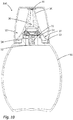
- Fig. 1 shows a liquid dispenser 100 according to the invention, which is designed in the manner of a drop dispenser.
- This liquid dispenser 100 has a liquid reservoir 90 designed as a squeeze bottle and a discharge head 10 placed thereon, on which a discharge opening 38 is provided. For closing the liquid dispenser, a cap 110 is provided.
- the liquid dispenser serves to deliver drops, for example of cosmetic liquids such as oils, make-up, fillers or the like in drop form.
- the intended operation provides that the entire dispenser is brought into an approximately overhead position with downwardly directed discharge opening 38 and that in this position, the liquid storage 90 on opposite sides in the region of actuation surfaces 92 kraftbeaufschlagt and compressed so that the liquid storage contained liquid is pressurized and is conveyed to the discharge opening 38.
- the liquid collects on a drop formation surface 26A surrounding the discharge opening 38 and dissolves as intended in the form of individual drops.
- the technical design of the discharge head 10 explained below serves the purpose of jointly achieving that, on the one hand, a drop delivery takes place even with only slight pressure on the squeeze bottle and, on the other hand, ensuring that even a strong actuation or compression of the liquid store 90 does not lead to the delivery of liquid in the form of a liquid jet leads.
- FIG. 2 Referring to the sectional view in FIG Fig. 2 embodiment shown can be seen in connection with a first embodiment, that the outlet channel 30 from an adjacent to the interior of the liquid reservoir 90 inlet portion 32 through two throttle channels 50 of a throttle device 34 and through openings 25A of the housing 20 into the region of an outlet valve 36 and continues to the discharge opening 38 extends.
- the outlet valve 36 is designed such that it can open both in the outlet direction and in the inlet direction at overpressure or underpressure in the liquid storage, so that the discharge duct 30 can also serve in the reverse direction as a ventilation duct after discharge and a sucking back of the liquid from the Outlet passage 30 allowed.
- the outlet valve 36 closes when neither overpressure nor underpressure prevails in the liquid storage 90 relative to the environment or the overpressure or underpressure does not exceed a limit value. This ensures that the risk of unintentional leakage when handling the liquid dispenser 100 is low.
- the discharge head 10 has a very simple structure. Beyond the design of the throttle device 34, which will be explained below, the discharge head 10 is made up of only three components, namely a two-part housing 20 with a base component 22 and an applicator component 26 and a fixed between these two components fastening ring designed as a one-piece elastic member outlet valve 36. In addition, a sealing ring 80 is provided for sealing the discharge head 10 relative to the liquid storage 90 in the embodiment yet.
- the throttle device 34 comprises a partition wall 25 belonging to the base component 22, which at the same time constitutes a first stationary duct wall 56 of the throttle duct 50.
- the second opposite channel wall is formed by the inside 52A of an elastically deformable wall plate 54, which is clipped to the base member 22 in the region of a fastening pin 25C.
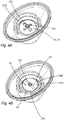
- FIGS. 4A and 4B showing the base member 22 without and with the wall plate 54 fixed, this will be explained in more detail.
- Fig. 4A Based on Fig. 4A it can be seen that the housing wall 25 is penetrated by two openings 25A. Next is in Fig. 4A to recognize that in the region of the fastening pin 25C on the partition wall 25 on both sides of the fastening pin 25C a striven, elongated elevation is provided. This separates two throttle channels 50, which by fastening the wall plate 54 in the in Fig. 4B clarified manner arise on the fixing pin 25C.
- the operation is the following: Based on the position of Fig. 2 in which the discharge opening 38 faces upward, the liquid dispenser 100 is brought into an overhead position. A liquid discharge alone by this is not to be feared, since the outlet valve 36 is designed not to open alone by the weight of the liquid in the liquid storage. Only when the liquid storage device 90 designed as a squeeze bottle is pressed together does liquid flow from the inlet region 32 into the respectively approximately semicircular throttle channels 50 in the direction of the apertures 25A, through which the liquid then passes into the region of the outlet valve 36 and on to the discharge opening 38.
- the design of the Figs. 5A and 5B is largely similar to that of FIGS. 4A and 4B , The only difference is that the surveys 25B in the case of the design of the Figs. 5A and 5B have a different shape and not, as in Fig. 4A clarified, are designed only elongated striven. Instead, the elevations have approximately the shape of a quarter circle, so that the in Fig. 5B shown lines along which the wall plate 54 deforms as intended, not aligned. The effect of this is that the tapering of the throttle channel under other boundary conditions than in the embodiment of FIGS. 4A and 4B takes place. In this way, the liquid dispenser 100 can be adapted with a comparatively small adaptation for different liquids.
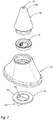
- the throttle device 34 is designed differently.
- the throttle device 34 of this embodiment has an elastic as a whole throttle member 62, which is penetrated by the throttle channel 60.
- the throttle member 62 has a planar edge region 68, on which a centrally rising in the direction of the liquid reservoir elevation 63 rises.
- the throttle channel 60 penetrates this elevation 63 and is surrounded by a deformation region 64 which deforms as intended.
- two pressurizing surfaces 65 are provided which are pressurized upon discharge of the liquid from this and thereby cause a deformation of the throttle channel 60.
- the throttle channel 60 has a circular open area 60B and slit-like closing areas 60A.
- This design is chosen so that when pressurizing no complete closing of the throttle channel 60 takes place.
- Figs. 9B to 9D show alternative designs.
- the slot-shaped portions of the throttle channel 60 are shaped so that they allow a complete closing.
- Circular free areas form the ends of the slot.
- free areas 60B and closing areas 60A are part of the same throttle channel 60. This is particularly useful for liquids that have an adhesion-enhancing tendency, since the always open remaining open area increases the tendency that the closing areas after the end of the discharge again separate from each other.
- FIGS. 11A and 11B show a third embodiment.
- the throttle channel 70 is here adjacent to a displaceable closing body 72 which, via a spring 74 in a sleeve structure 76, 72A in Direction of the final position of the Fig. 11A is charged with force. If an overpressure is built up in the liquid accumulator 90, this overpressure acts on the throttle body 72 on all sides. Due to the larger effective pressurization area for upward pressurization, the pressure prevailing on all sides acts in such a way that a force acts on the throttle body 72, which affects it the perspective of Figs. 11A and 11B shifted upwards.
- the throttle channel 70 is reduced in size with respect to its cross section and finally completely closed.
- the liquid can still partially flow past the throttle body 72, so that droplet formation still remains possible.
Description
Die Erfindung betrifft einen Austragkopf für einen Flüssigkeitsspender sowie einen Flüssigkeitsspender mit einem solchen Austragkopf.The invention relates to a discharge head for a liquid dispenser and a liquid dispenser with such a discharge head.
Ein gattungsgemäßer Austragkopf weist ein Gehäuse sowie eine Kopplungseinrichtung zur Anbringung an einem Flüssigkeitsspeicher auf. Er verfügt weiterhin über eine Austragöffnung, durch die hindurch Flüssigkeit in eine umgebende Atmosphäre ausgegeben werden kann, und über einen Auslasskanal, der sich von einem in Richtung des Flüssigkeitsspeichers weisenden Einlassbereich bis zur Austragöffnung erstreckt und mittels dessen die Austragöffnung mit Flüssigkeit versorgt werden kann.A generic discharge head has a housing and a coupling device for attachment to a liquid storage. It also has a discharge opening through which liquid can be discharged into a surrounding atmosphere, and via an outlet channel which extends from an inlet region pointing in the direction of the liquid storage to the discharge opening and by means of which the discharge opening can be supplied with liquid.
Bei einem gattungsgemäßen Spender und einem gattungsgemäßen Austragkopf ist vorgesehen, dass die Flüssigkeit im Flüssigkeitsspeicher oder in einer davon getrennten Druckkammer druckbeaufschlagt wird, um durch diesen Druck durch den Auslasskanal in Richtung der Austragöffnung gefördert zu werden. Je nach Art der Druckbeaufschlagung ist es einem Benutzer jedoch möglich, den Druck unmittelbarzu beeinflussen und somit auch die Flüssigkeit im Lichte des Verwendungszwecks mit einem zu hohen Druck zu beaufschlagen, beispielsweise durch die Kraft, mit der eine als Flüssigkeitsspeicher dienende Quetschflasche zusammengedrückt wird.In a generic dispenser and a generic discharge head is provided that the liquid in the liquid storage or in a separate pressure chamber is pressurized to be promoted by this pressure through the outlet channel in the direction of the discharge. However, depending on the nature of the pressurization, it is possible for a user to directly influence the pressure and thus also to pressurize the fluid in the light of the intended use with too high a pressure, for example by the force with which a squeeze bottle serving as a fluid reservoir is compressed.
Wirkung dieser benutzerabhängigen Druckbeaufschlagung kann dann beispielsweise sein, dass ein Flüssigkeitsstrahl an der Austragöffnung abgegeben wird, obwohl nur eine geringe Flüssigkeitsmenge zur Bildung von Tropfen bestimmungsgemäß ausgegeben werden sollte. Oder es kann ein Druck erzeugt werden, welcher zu einem Sprühbild mit zu feinen Tröpfchen führt.The effect of this user-dependent pressurization can then be, for example, that a liquid jet is discharged at the discharge opening, although only a small amount of liquid should be spent as intended to form droplets. Or a pressure can be generated which leads to a spray pattern with too fine droplets.
Um den Flüssigkeitsdruck und/oder den Flüssigkeitsstrom zu limitieren, ist es möglich, im Auslasskanal eine als Drossel wirkende Geometrie vorzusehen, beispielsweise einen Kanalabschnitt mit sehr geringem Querschnitt und/oder einer vergleichsweise großen Länge. Durch die hier sich einstellende Reibung kann der Flüssigkeitsdruck/der Flüssigkeitsstrom vermindert werden. Wirkung einer solchen Drossel ist dann jedoch, dass die Betätigung stets mit einer recht hohen Kraft erfolgen muss. Dies kann bei einigen Anwendungszwecken unproblematisch sein. Gerade bei Anwendungszwecken, bei denen eine ortsgenaue Abgabe der Flüssigkeit gewünscht ist, beispielsweise beim Applizieren von Augentropfen oder der punktgenauen Aufbringung von Make-up, ist es jedoch wünschenswert, dass bereits mit einer vergleichsweise leichten Betätigung der gewünschte Austragvorgang bewirkt werden kann. Ein Austragkopf der oben genannten Art wird in
Aufgabe der Erfindung ist es, einen Austragkopf und einen Flüssigkeitsspender zur Verfügungzu stellen, die bereits bei geringer Druckbeaufschlagung der Flüssigkeit in bestimmungsgemäßer Weise diese durch die Austragöffnung hindurch abgeben können, gleichzeitig jedoch bei zu starker Betätigung den Flüssigkeitsdruck und/oder den Flüssigkeitsstrom so begrenzen, dass eine bestimmungsgemäße Abgabeform der Flüssigkeit möglich bleibt.The object of the invention is to provide a discharge head and a liquid dispenser are available, which can give them through the discharge opening already at low pressurization of the liquid in the intended manner, but at the same time limit the fluid pressure and / or the liquid flow at excessive actuation so that a proper delivery form of the liquid remains possible.
Hierfür ist vorgesehen, dass der Austragkopf im Auslasskanal über eine Drosseleinrichtung mit einem Drosselkanal zur Verringerung des Flüssigdrucks und/oder des Flüssigkeitsstroms der die Drosseleinrichtung durchströmenden Flüssigkeit verfügt.For this purpose, it is provided that the discharge head in the outlet channel has a throttle device with a throttle channel for reducing the liquid pressure and / or the liquid flow of the liquid flowing through the throttle device.
Erfindungsgemäß ist diese Drosseleinrichtung als dynamische Drosseleinrichtung ausgebildet, bei der ein freier Querschnitt des Drosselkanals bei ansteigendem an der Drosseleinrichtung anliegendem Druck oder bei höherem die Drosseleinrichtungdurchströmenden Flüssigkeitsstrom verringert wird.According to the invention, this throttle device is designed as a dynamic throttle device, in which a free cross-section of the throttle channel is reduced with increasing applied to the throttle device pressure or at higher throttle device flowing through the liquid stream.
Ein erfindungsgemäßer Austragkopf weist ebenso wie ein gattungsgemäßer Austragkopf einen Auslasskanal auf, an dessen Ende die Austrittsöffnung vorgesehen ist. Dieser Auslasskanal verbindet einen Flüssigkeitsspeicher des Flüssigkeitsspenders mit der Austragöffnung, so dass bei Druckbeaufschlagung der Flüssigkeit im Flüssigkeitsspeicher als Ganzem oder aber Druckbeaufschlagung einer Teilcharge der Flüssigkeit diese in Richtung der Austragöffnung gefördert und dort abgegeben wird. Um einen zu hohen Druck und/oder einen zu hohen Flüssigkeitsstrom an der Austrittsöffnung zu vermeiden, ist die genannte dynamische Drosseleinrichtung vorgesehen. Diese dynamische Drosseleinrichtung weist die Besonderheit auf, dass sie den Strömungswiderstand in Abhängigkeit von Betätigungsparametern anpasst. Dies erfolgt, indem ein freier Querschnitt des Drosselkanals bei höherem Druck oder höherem Flüssigkeitsstrom verringert wird. Eine solche Verringerung kann beispielsweise darin bestehen, dass jenseits einer ersten Drosselstelle im Auslasskanal durch Verlagerung einer Drosselfläche eine weitere Drosselstelle entsteht, deren freier Querschnitt geringer als der der ersten Drosselstelle ist. Insbesondere kann eine Wandung des Drosselkanals eine Verlagerung erfahren, so dass der Drosselkanal hierdurch seinen freien Querschnitt verringert.An inventive discharge head, like a generic discharge head, has an outlet channel at the end of which the outlet opening is provided. This outlet channel connects a liquid reservoir of the liquid dispenser with the discharge opening, so that upon pressurization of the liquid in the liquid storage as a whole or pressurizing a partial charge of the liquid it is conveyed in the direction of the discharge and discharged there. In order to avoid too high a pressure and / or too high a liquid flow at the outlet opening, said dynamic throttle device is provided. This dynamic throttle device has the special feature that it adapts the flow resistance as a function of operating parameters. This is done by reducing a free cross section of the throttle channel at higher pressure or higher liquid flow. Such a reduction may be, for example, that beyond a first throttle point in the outlet channel by shifting a throttle surface, a further throttle point is formed whose free cross-section less than which is the first throttle point. In particular, a wall of the throttle channel undergo a displacement, so that the throttle channel thereby reduces its free cross-section.
Im einfachsten Falle kann die dynamische Drosseleinrichtung so ausgebildet sein, dass sie üblicherweise nur einen von zwei möglichen Zuständen einnimmt, einem nicht oder kaum drosselnden und einem stärker drosselnden. Bevorzugt ist jedoch eine Gestaltung, bei der die Drosselwirkung gleichsam analogeintritt, so dass bei steigender Druckbeaufschlagung oder steigendem Flüssigkeitsstrom eine kontinuierlich steigende Drosselwirkung erzielt wird. Wenngleich es nicht ausgeschlossen ist, die dynamische Drosseleinrichtung so auszugestalten, dass sie bei zu hohem Druck vollständig schließt, wird es als vorteilhaft angesehen, wenn die dynamische Drosseleinrichtung derart ausgebildet ist, dass sie den Drosselkanal nie vollständig schließt.In the simplest case, the dynamic throttle device may be designed so that it usually occupies only one of two possible states, one or hardly throttling and one more throttling. However, preference is given to a design in which the throttling effect, as it were, occurs analogously, so that a continuously increasing throttling effect is achieved with increasing pressurization or increasing liquid flow. Although it is not excluded that the dynamic throttle device may be designed to close completely when the pressure is too high, it is considered advantageous if the dynamic throttle device is designed such that it never completely closes the throttle passage.
Bestimmungsgemäß passt sich die dynamische Drosseleinrichtung in Abhängigkeit von Betriebsparametern jeweils an, nämlich in Abhängigkeit des anliegenden Drucks oder des Flüssigkeitsstroms, wobei je nach Ausgestaltung die beiden genannten Größen miteinander gekoppelt sind oder jeweils eine Anpassung der dynamischen Drosseleinrichtung bewirken. Eine Ausgestaltung der Drosseleinrichtung, die unmittelbar durch Druck zu einer Verringerung des freien Querschnitts des Drosselkanals führt, kann beispielsweise gegeben sein, wenn unterschiedlich große Druckbeaufschlagungsflächen an einer verlagerbaren Wandung des Drosselkanals dafür sorgen, dass steigender Druck eine Auslenkung dieser Wandung bewirken. Der Flüssigkeitsstrom kann die Verlagerung einer Kanalwandung des Drosselkanals auch bewirken, wenn beidseitig dieser Wandung ein identischer Gesamtdruck anliegt, da die erhöhte Flüssigkeitsgeschwindigkeit im Drosselkanal nach Bernoulli zu einem dort geringeren statischen Druck führt, was wiederum benutzt werden kann, um den Drosselkanal zu verjüngen.According to the invention, the dynamic throttle device adapts depending on operating parameters in each case, namely as a function of the applied pressure or the fluid flow, depending on the embodiment, the two variables mentioned are coupled together or each cause an adjustment of the dynamic throttle device. An embodiment of the throttle device, which leads directly by pressure to a reduction in the free cross section of the throttle channel, may be given, for example, if different sized pressurization surfaces on a displaceable wall of the throttle channel ensure that increasing pressure cause a deflection of this wall. The liquid flow can also cause the displacement of a channel wall of the throttle channel when an identical total pressure is present on both sides of this wall, since the increased fluid velocity in the throttle channel according to Bernoulli leads to a lower static pressure there, which in turn can be used to taper the throttle channel.
Der Drosselkanal ist erfindungsgemäß zumindest abschnittsweise durch eine Innenseite einer durch Verlagerung oder Verformung ortsveränderlichen Kanalwandung begrenzt.According to the invention, the throttle channel is delimited at least in sections by an inner side of a channel wall that is movable by displacement or deformation.
Bei einer Veränderung des Drosselkanals durch Verlagerung einer Kanalwandung ist vorzugsweise vorgesehen, dass diese Kanalwandung in sich starr ist und Teil eines Drosselbauteils, welches als Ganzes verlagert wird. Dies wird im Weiteren noch erläutert.In a change of the throttle channel by displacement of a channel wall is preferably provided that this channel wall is rigid in itself and part of a throttle component, which is displaced as a whole. This will be explained below.
Bei einer Begrenzungdes Drosselkanals durch eine verformbare Kanalwandung ist vorgesehen, dass ein verformbares und vorzugsweise elastisches Bauteil, welches somit anschließend in seine Ausgangsposition zurückkehren kann, verwendet wird, um einen variablen Querschnitt des Drosselkanals zu bewirken.When the throttle duct is delimited by a deformable duct wall, it is provided that a deformable and preferably elastic component, which can thus subsequently return to its starting position, is used to effect a variable cross-section of the throttle duct.
Eine der Innenseite abgewandte Außenseite der Kanalwandung kann kommunizierend mit einem Einlass des Drosselkanals verbunden sein, so dass bei Druckbeaufschlagung der Flüssigkeit zum Zwecke des Austrags ein identischer Druckanstieg am Einlass des Drosselkanals und an der Außenseite der Kanalwandung erfolgt.An outside of the channel wall facing away from the inside can be communicatively connected to an inlet of the throttle channel, so that when the fluid is pressurized for the purpose of discharge, an identical pressure increase takes place at the inlet of the throttle channel and on the outside of the channel wall.
Eine Gestaltung, bei der sich beidseitig der Kanalwandung sich ein identischer Gesamtdruck einstellt, ist deshalb von Vorteil, da nicht die Druckbeaufschlagung der Flüssigkeit als solche eine Veränderung des Querschnitts des Drosselkanals bewirkt, sondern erst der Anstieg des dynamischen Drucks und der Abfalls des statischen Drucks im Drosselkanal. Der dynamische Druck ergibt sich aufgrund der Geschwindigkeit des Flüssigkeitsstroms im Drosselkanal. Da es üblicherweise bei einer erfindungsgemäßen Ausgestaltung eines Austragkopfes das Ziel ist, den Flüssigkeitsstrom zu limitieren, ist eine solche Lösung vorteilhaft, bei der auch unmittelbar der Flüssigkeitsstrom und seine Geschwindigkeit jene Größe ist, die zu einer Verjüngung des Drosselkanals führt und damit zu einer Erhöhung der Reibung gegenüber den Wandungen und innerhalb in Flüssigkeit und dadurch zu einer Verminderung des Flüssigkeitsstroms. Gewissermaßen limitiert sich der Flüssigkeitsstrom somit unmittelbar selbst.A design in which sets an identical total pressure on both sides of the channel wall, is therefore advantageous because not the pressurization of the liquid as such causes a change in the cross section of the throttle channel, but only the increase of the dynamic pressure and the drop in the static pressure in throttle channel. The dynamic pressure is due to the velocity of the liquid flow in the throttle channel. Since it is usually in an inventive embodiment of a discharge head the goal is to limit the liquid flow, such a solution is advantageous in which also the liquid flow and its velocity is that size which leads to a taper of the throttle channel and thus to an increase in Friction against the walls and within in liquid and thereby to a reduction of the liquid flow. In a sense, the liquid flow is therefore limited itself.
Die ortsveränderliche Kanalwandung kann Teil einer planen und vorzugsweise verformbaren Wandungsplatte sein. Dieser zumindest partiell gegenüber dem Gehäuse ortsveränderlichen Kanalwandung gegenüberliegend kann eine ortsfeste Kanalwandung vorgesehen sein, wobei die ortsveränderliche Kanalwandung und die ortsfeste Kanalwandung zwischen sich den Drosselkanal definieren.The portable channel wall may be part of a flat and preferably deformable wall plate. This at least partially opposite to the housing ortsveränderlichen channel wall can be provided a stationary channel wall, wherein the portable channel wall and the fixed channel wall define the throttle channel between them.
Diese Bauweise hat sich als sehr einfach und zuverlässig herausgestellt. Der Drosselkanal wird hierbei durch einen Spalt zwischen der unverformt planen Wandungsplatte und der zum Gehäuse ortsfesten Kanalwandung gebildet. Die plane und vorzugsweise verformbare Wandungsplatte ist vorzugsweise in einem Befestigungsbereich ortsfest zur ortsfesten Kanalwandung befestigt und ragt unter Bildung des Spaltes über diese ortsfeste Kanalwandung. Insbesondere von Vorteil ist es, wenn die ortsfeste Kanalwandung darüber hinaus mindestens eine Durchbrechung aufweist, die gleichsam das Ende des Drosselkanals darstellt und in die die Flüssigkeit einströmt, die den Drosselkanal durchquert hat. Eine besonders einfache Möglichkeit zur Befestigung der planen und vorzugsweise verformbaren Wandungsplatte ist es, dass diese mit einer Durchbrechung versehen ist, die auf einen gehäuseseitigen Befestigungsstift aufgeschoben und dort befestigt, beispielsweise verschnappt wird.This construction has proven to be very simple and reliable. The throttle channel is in this case formed by a gap between the undeformed plan wall plate and the housing stationary channel wall. The flat and preferably deformable Wandungsplatte is preferably fixed in a mounting area fixed to the stationary channel wall and projects to form the gap on this stationary channel wall. In particular, it is advantageous if the stationary channel wall also has at least one opening which, as it were, represents the end of the throttle channel and into which the liquid flows, which has passed through the throttle channel. A particularly simple way of attaching the flat and preferably deformable wall plate is that it is provided with an opening which is pushed onto a housing-side fixing pin and fastened there, for example, snapped.
Der Austragkopf kann mehrere zueinander parallel geschaltete Drosselkanäle aufweisen. Die Wandungsplatte kann dabei als gemeinsame Wandungsplatte vorgesehen sein, die die mindestens zwei Drosselkanäle abschnittsweise begrenzt.The discharge head may have a plurality of mutually parallel throttle channels. The wall plate can be provided as a common wall plate, which limits the at least two throttle channels in sections.
Wenngleich naturgemäß ein Drosselkanal zur Erzielung des gewünschten Zweckes ausreicht, kann es von Vorteil und baulich sehr einfach möglich sein, mehrere parallel geschaltete Drosselkanäle vorzusehen. Unter der Parallelschaltung wird dabei verstanden, dass die Flüssigkeit nur einen dieser parallel geschalteten Drosselkanäle durchqueren muss. Die Anordnung, bei der eine gemeinsame Wandungsplatte beide Drosselkanäle abschnittsweise begrenzt, führt zu einer Reduktion von Bauteilen und ist durch eine punkt- oder liniensymmetrische Ausgestaltung auch sehr einfach erzielbar. So kann die Wandungsplatte im Bereich eines Steges zwischen den Drosselkanälen befestigt sein und bestimmungsgemäß sich beidseitig dieses Steges verformen, um eine Verjüngung der dort vorgesehenen zwei Drosselkanäle zu bewirken. Je nach konkretem Anwendungszweck kann es zur Anpassungdes Drosselverhaltens auch zweckmäßigsein, mehr als zwei Drosselkanäle vorzusehen, insbesondere vier Drosselkanäle. An der Gehäusewandung oder der Wandungsplatte kann mindestens eine Erhebung vorgesehen sein, im Bereich derer die Gehäusewandung und die Wandungsplatte aneinander anliegen.Although naturally a throttle channel sufficient to achieve the desired purpose, it may be advantageous and structurally very easy to provide a plurality of parallel-connected throttle channels. The parallel connection is understood to mean that the fluid only has to pass through one of these throttle channels connected in parallel. The arrangement in which a common wall plate limits both throttle channels in sections, leads to a reduction of components and is also very easy to achieve by a point or line-symmetrical design. Thus, the Wandungsplatte be secured in the region of a web between the throttle channels and intended deform on both sides of this web to effect a taper of the two throttle channels provided there. Depending on the specific application, adapting the throttle behavior may also be expedient for providing more than two throttle channels, in particular four throttle channels. At least one elevation may be provided on the housing wall or the wall plate, in the region of which the housing wall and the wall plate abut one another.
Durch die Gehäusewandung und die Wandungsplatte ist in bereits genannter Weise ein Spalt definiert, der den Drosselkanal darstellt. Durch die genannten Erhebungen bzw. deren Kanten wird dieser Spalt zusätzlich begrenzt. Im Bereich der Erhebungen liegen die Gehäusewandung und die Wandungsplatte aneinander an, wobei es insbesondere von Vorteil ist, wenn die Erhebung auf Seiten der Gehäusewandung vorgesehen ist, da die verformbare Wandungsplatte dann als erhebungsfreie plane und dadurch günstig herstellbare Wandungsplatte gestaltet sein kann.Through the housing wall and the Wandungsplatte a gap is defined in the aforementioned manner, which represents the throttle channel. Due to the aforementioned elevations or their edges, this gap is additionally limited. In the region of the elevations, the housing wall and the wall plate abut each other, wherein it is particularly advantageous if the elevation is provided on the side of the housing wall, since the deformable wall plate can then be designed as elevation-free plane and thus low producible wall plate.
Die Erhebungen und insbesondere die Ränder dieser Erhebung, die gleichzeitig die Ränder des Drosselkanals bilden, können auf einfache Weise genutzt werden, um die Neigung der Wandungsplatte zur drosselnden Verformung beeinflussen zu können. Wenn beispielsweise eine geradlinige stegartige Erhebung vorgesehen ist, so bedarf es zur Verformung der im Bereich dieser Erhebung befestigten Wandungsplatte lediglich eines Einknickens der Wandungsplatte der stegartigen Erhebung folgend. Sind jedoch Erhebungen vorgesehen, deren in Richtung des Drosselkanals weisenden Kanten einen Winkel kleiner 180° einschließen, beispielsweise einen Winkel von etwa 90°, so muss die Wandungsplatte zum Zwecke derVerformung entlang zweier nicht paralleler Linien einknicken, was einen höheren Grad an Kraftbeaufschlagung verlangt. Die Formgebung der Erhebungen kann daher insbesondere auch genutzt werden, um im Übrigen baugleiche Austragköpfe an verschiedene Flüssigkeiten und deren spezifische Eigenschaften anzupassen oder um den maximalen Austragdruck/Austragflüssigkeitsstrom im Lichte des Anwendungsfeldes beeinflussen zu können.The elevations and in particular the edges of this elevation, which at the same time form the edges of the throttle channel, can be used in a simple manner in order to be able to influence the inclination of the wall plate for throttling deformation. If, for example, a rectilinear web-like elevation is provided, deformation of the wall plate fastened in the area of this elevation requires only a buckling of the wall plate of the web-like elevation. However, if projections are provided whose edges pointing in the direction of the throttle channel include an angle of less than 180 °, for example an angle of approximately 90 °, the wall plate must buckle along two non-parallel lines for the purpose of deformation, which requires a higher degree of force. The shape of the surveys can therefore in particular also be used to adapt otherwise identical discharge heads to different liquids and their specific properties or to influence the maximum discharge / discharge liquid flow in the light of the field of application.
Alternativ zu der beschriebenen Gestaltung, bei der der Drosselkanal durch eine ortsfeste und vorzugsweise starre Wandung und eine ortsveränderliche Wandung begrenzt ist, kann auch vorgesehen sein, dass der Austragkopf ein Drosselbauteil aus einem elastisch verformbaren Material als Teil der Drosseleinrichtungaufweist. Dieses Drosselbauteil verfügt über eine von einem Verformungsbereich umgebene Durchbrechung, die den Drosselkanal bildet.As an alternative to the described configuration, in which the throttle duct is delimited by a stationary and preferably rigid wall and a movable wall, it can also be provided that the discharge head has a throttle component of an elastically deformable material as part of the throttle device. This throttle component has an opening surrounded by a deformation region, which forms the throttle channel.
Das Drosselbauteil weist zusätzlich vorzugsweise mindestens eine Druckbeaufschlagungsfläche auf, an der im Betrieb die Flüssigkeit stromaufwärts des Drosselkanals anliegt und durch deren Druckbeaufschlagung der Verformungsbereich verformt und ein freier Querschnitt des Drosselkanals verringerbar ist.In addition, the throttle component preferably has at least one pressurization surface against which the liquid rests upstream of the throttle channel during operation and by the pressurization of which the deformation region is deformed and a free cross section of the throttle channel can be reduced.
Bei dieser alternativen Gestaltung ist vorgesehen, dass der Drosselkanal an einem als Ganzem verformbaren Drosselbauteil in Form einer umlaufend umgebenen Durchbrechung vorgesehen ist, wobei die diese Durchbrechung, also den Drosselkanal, umgebenden Bereiche den Verformungsbereich bilden und durch Druckbeaufschlagung oder einen Flüssigkeitsstrom so verformt werden können, dass der freie Querschnitt des Drosselkanals sich verändert.In this alternative embodiment, it is provided that the throttle channel is provided on a deformable as a whole throttle member in the form of a circumferentially surrounded aperture, which form this opening, ie the throttle channel surrounding areas forming the deformation region and can be deformed by pressurization or a liquid flow, that the free cross section of the throttle channel changes.
Da der Drosselkanal bei einer solchen Gestaltung alleine durch ein Bauteil definiert ist, kann eine sehr geringe Streuung der Verhaltensweise baugleicher Austragköpfe erzielt werden. Anders als bei einer Gestaltung, bei der der Drosselkanal durch mehrere Bauteile gebildet wird, kommt es bei dieser Gestaltung kaum auf eine besondere Montagegenauigkeit an.Since the throttle channel is defined in such a design solely by a component, a very small dispersion of the behavior of identical discharge heads can be achieved. Unlike a design in which the throttle channel is formed by a plurality of components, it comes in this design hardly a special mounting accuracy.
Hinzu kommt, dass die Montage aufgrund der Ausgestaltung des Drosselkanals aus nur einem Bauteil sehr einfach ist.In addition, the assembly is very easy due to the design of the throttle channel of only one component.
Das Drosselbauteil kann eine in stromaufwärtige Richtung gewölbte Erhebung aufweisen, in der der Drosselkanal vorgesehen ist. Hierdurch wird erzielt, dass die wunschgemäß vorgesehene Verjüngung des Drosselkanals sich zuverlässig einstellt, wenn der Flüssigkeitsdruck von verschiedenen Seiten aus auf die Erhebung drückt. Der Drosselkanal durchbricht die Erhebung vorzugsweise an deren erhabensten Punkt.The throttle component may have a curved in the upstream direction elevation, in which the throttle channel is provided. This ensures that the desired intended taper of the throttle channel adjusts reliably when the fluid pressure from different sides presses on the survey. The throttle channel breaks through the survey preferably at its most sublime point.
Das Drosselbauteil kann einen einstückig mit dem Verformungsbereich verbundenen außenseitigen umlaufenden Randbereich aufweisen.The throttle component may have an outer circumferential edge region connected in one piece with the deformation region.
Im Bereich dieses Randes kann das elastische Drosselbauteil durch eine Schnappverbindung oder insbesondere eine einstückige Anformung an einem starren Gehäuseabschnitt des Gehäuses befestigt sein.In the region of this edge, the elastic throttle component can be fastened by a snap connection or in particular a one-piece molding on a rigid housing portion of the housing.
Die Befestigung des Drosselbauteils an einem Gehäuseabschnitt des Gehäuses des Austragkopfes ist von Vorteil, da hierdurch eine Vormontageeinheit geschaffen wird, die selbst bei der Handhabung als Schüttgut nicht Gefahr läuft, das elastische Drosselbauteil zu beschädigen. Dieses ist vorzugsweise derart gegenüber Wandungen des Gehäuses zurückgesetzt, dass es gehandhabt als Schüttgut nicht durch andere Austragköpfe des Schüttgutes verletzt wird. Dies hat sich in der Praxis als vorteilhaft herausgestellt, da anderenfalls die Gefahr besteht, dass das Drosselbauteil nach Beschädigung als Schüttgut nicht mehr in der gewünschten Weise drosselnd reagiert.The attachment of the throttle member to a housing portion of the housing of the discharge head is advantageous because a pre-assembly is created by this, which does not run the risk even when handling bulk material to damage the elastic throttle component. This is preferably set back against walls of the housing that handled as bulk material is not injured by other discharge heads of the bulk material. This has proven to be advantageous in practice, since otherwise there is the danger that the throttle component after damage as bulk material no longer reacts throttling in the desired manner.
Von besonderem Vorteil ist die einstückige Anformung, bei der vorzugsweise durch Zweikomponentenspritzguss der genannte starre Gehäuseabschnitt und das elastische Drosselbauteil einstückig aus verschiedenen Materialien hergestellt werden. Die Anzahl der im Zuge einer Montage zu fügenden Bauteile lässt sich dadurch verringern. Zudem ist eine sehr genaue und bleibende Positionierung des Drosselbauteils relativ zum Gehäuse hierdurch gewährleistet.Of particular advantage is the one-piece molding, in which preferably by two-component injection molding of said rigid housing portion and the elastic throttle member are integrally made of different materials. The number of components to be joined in the course of assembly can thereby be reduced. In addition, a very accurate and permanent positioning of the throttle member relative to the housing is thereby ensured.
Der Randbereich kann derart angeordnet sein, dass er bei Ankoppelung des Flüssigkeitsspeichers den Flüssigkeitsspeicher gegen das Gehäuse abdichtet. Durch diese Verwendung des Randbereiches des Drosselbauteils als Dichtung zwischen dem Austragkopf und dem Flüssigkeitsspeicher kann ein separates Bauteil hierfür entfallen. Der Austragkopf kann daher mit sehr wenigen Bauteilen und dementsprechend geringem Montageaufwand gefertigt werden.The edge region can be arranged such that it seals the liquid reservoir against the housing when the liquid reservoir is coupled. By this use of the edge region of the throttle component as a seal between the discharge and the liquid storage a separate component can be omitted. The discharge head can therefore be manufactured with very few components and correspondingly low installation costs.
Der Drosselkanal kann bei einer besonderen Ausgestaltung mindestens einen Schließbereich und mindestens einen Freibereich aufweisen, die gemeinsam und ineinander übergehend den Querschnitt des Drosselkanals bilden. Im Schließbereich findet durch Kraftbeaufschlagung der Druckbeaufschlagungsfläche ein Anliegen gegenüberliegender Kanten des Drosselkanals statt. Der Freibereich ist durch eine Kantenanordnung begrenzt, die selbst bei Kraftbeaufschlagung der Druckbeaufschlagungsfläche nicht zu einem Schließen des Freibereichs führt.In a particular embodiment, the throttling channel may have at least one closing region and at least one free region, which together form the cross section of the throttle channel together and into one another. In the closing area, an application of opposing edges of the throttle channel takes place by application of force to the pressurizing surface. The free area is limited by an edge arrangement which does not lead to a closing of the free area even when the pressurization area is acted on by force.
Die genannte Gestaltung sieht demnach vor, dass der Drosselkanal eine Querschnittsfläche aufweist, die einen druck- oder flüssigkeitsstromabhängigen Teilbereich, den Schließbereich, aufweist, der bei hohem Druck oder hohem Flüssigkeitsstrom schließt. Zudem ist jedoch auch ein Freibereich vorgesehen, der selbst bei höchsten im realen Betrieb anzunehmenden Drücken und Flüssigkeitsströmen offen bleibt.The said design therefore provides that the throttle channel has a cross-sectional area which has a pressure or liquid flow-dependent portion, the closing area, which closes at high pressure or high liquid flow. In addition, however, a free area is provided, which remains open even at the highest to be assumed in real operation pressures and liquid flows.
Es ist somit gewährleistet, dass ein vollständiges Verschließen des Drosselkanals selbst bei hohen Drücken nicht stattfindet. Dies entspricht dem Wunsch, einen Austrag bei zu starker Kraftbeaufschlagung nicht zu unterbinden, sondern so weit zu dämpfen, dass das gewünschte Austragbild sich einstellt.It is thus ensured that a complete closing of the throttle channel does not take place even at high pressures. This corresponds to the desire not to prevent a discharge in case of excessive force, but to dampen so far that the desired Austragbild sets.
Durch die gemeinsame Realisierung des Schließbereichs und des Freibereichs als Teil des Querschnitts des gleichen Drosselkanals wird zudem erreicht, dass nach Verjüngung des Drosselkanals durch Schließen des Schließbereichs eine verstärkte Neigung des Schließbereichs gegeben ist, sich nach Wegfall des schließenden Drucks wiederzu öffnen. Gerade im Hinblick darauf, dass mittels des erfindungsgemäßen Austragkopfes auch klebrige Massen ausgetragen werden können sollen, ist dies von Vorteil.By the joint realization of the closing area and the free area as part of the cross section of the same throttle channel is also achieved that after rejuvenation of the throttle channel by closing the closing area an increased inclination of the closing area is given to reopen after elimination of the closing pressure. Especially in view of the fact that even sticky masses should be able to be discharged by means of the discharge head according to the invention, this is advantageous.
Die abschnittsweise Gestaltung des Drosselkanals als Schließbereich oder als Freibereich lässt sich durch die Wahl der Geometrie bestimmen. So ist ein schlitzförmiger Abschnitt des Querschnitts des Drosselkanals geeignet, komplett zu schließen und somit einen Schließbereich darzustellen. Ein kreisförmiger oder polygonaler Ausschnitt des Drosselkanals wird jedoch selbst bei hohen Drücken nicht komplett schließen und stellt somit einen Freibereich dar.The sectional design of the throttle channel as a closing area or as a free area can be determined by the choice of geometry. Thus, a slot-shaped portion of the cross section of the throttle channel is suitable to close completely and thus represent a closing area. However, a circular or polygonal section of the throttle channel will not close completely even at high pressures and thus represents a free area.
Wenngleich es als vorteilhaft angesehen wird, einen gemeinsamen Drosselkanal mit einem solchen Schließbereich und einem Freibereich auszugestalten, ist auch eine Gestaltung denkbar, bei der zwei parallel geschaltete Kanäle gemeinsam eine Drosselkanalanordnung bilden, wobei einer dieser Kanäle einen Freibereich aufweist, während der andere Kanal druck- oderflüssigkeitsstromabhängig komplett schließt. Insbesondere bei Flüssigkeiten, die das bleibende Anhaften gegenüberliegender Kanten oder Wandungen des Drosselkanals nicht begünstigen, kann auch eine solche Gestaltung zweckmäßig sein.Although it is considered advantageous to design a common throttle channel with such a closing area and an open area, a design is also conceivable in which two channels connected in parallel form a throttle channel arrangement, one of these channels having a free area, while the other channel is pressurized. or liquid flow dependent completely closes. In particular, in liquids that do not favor the permanent adhesion of opposite edges or walls of the throttle channel, such a design may be appropriate.
Alternativ zu den beschriebenen Gestaltung, bei denen der Drosselkanal vorzugsweise abschnittsweise durch zumindest eine formveränderliche Wandung begrenzt ist, ist bei einer weiteren Variante vorgesehen, dass der Drosselkanal durch zwei starre Kanalwandungen begrenzt wird, wobei eine der Kanalwandungen als ortsveränderliche Kanalwandung an einem ortsveränderlichen Drosselbauteil vorgesehen ist.As an alternative to the described design, in which the throttle channel is preferably bounded in sections by at least one dimensionally variable wall, is provided in a further variant that the throttle channel is limited by two rigid channel walls, one of the channel walls is provided as a portable channel wall on a movable throttle member ,
Bei dieser Gestaltung wird der Drosselkanal durch starre Wandungen begrenzt, die als Ganzes relativ zueinander beweglich sind. Mindestens eine dieser Wandungen ist, vorzugsweise gegen die Kraft einer Rückstellfeder, auslenkbar, wobei durch diese Auslenkung der freie Querschnitt des Drosselkanals verringert wird.In this design, the throttle channel is limited by rigid walls, which are movable as a whole relative to each other. At least one of these walls is, preferably against the force of a return spring, deflected, which is reduced by this deflection of the free cross section of the throttle channel.
Dieses ortsveränderliche Drosselbauteil ist vorzugsweise mittels einer Führung gegenüber dem Gehäuse geführt, wobei diese Führung insbesondere durch zwei teleskopartig ineinandergeschobene Hülsen gebildet werden kann. Die genannte Federkraft wird vorzugsweise durch eine Federeinrichtung erzeugt, die bei einer besonders vorteilhaften Gestaltung in dem durch die Hülsen gebildeten Freiraum angeordnet ist.This movable throttle component is preferably guided by means of a guide relative to the housing, wherein this guide can be formed in particular by two telescopically telescoped sleeves. Said spring force is preferably generated by a spring device, which is arranged in a particularly advantageous design in the space formed by the sleeves.
Von besonderem Vorteil ist es, wenn das Drosselbauteil derart beschaffen und/oder am Gehäuse angebracht ist, dass zur Verlagerung wirksamer Druckbeaufschlagungsflächen am Drosselbauteil bei identischem Druck an allen Druckbeaufschlagungsflächen eine Kraftbeaufschlagung des Drosselbauteils in Richtung einer Verringerung des freien Querschnitts des Drosselkanals bewirken. Dies bedeutet, dass alleine der statische Druck, der zum Zwecke des Austrags aufgebracht wird, in der Lage ist, das Drosselbauteil im Sinne einer Verjüngung des Drosselkanals zu verlagern.It is particularly advantageous, when the throttle component is such and / or mounted on the housing, that for the displacement of effective pressurizing surfaces on the throttle member at identical pressure on all pressurization surfaces cause a force to the throttle member in the direction of a reduction of the free cross section of the throttle channel. This means that only the static pressure, which is applied for the purpose of discharge, is able to shift the throttle component in the sense of a taper of the throttle channel.
Vorzugsweise weist der Austragkopf im Auslasskanal stromabwärts der Drosseleinrichtung ein Auslassventil auf, welches in Abhängigkeit des stromaufwärts anliegenden Überdrucks öffnet.Preferably, the discharge head in the outlet channel downstream of the throttle device to an outlet valve, which opens depending on the upstream applied pressure.
Ein solches Ventil führt dazu, dass die Gefahr des Auslaufens des Spenders verringert wird. Da jedoch insbesondere ein Tropfenspender auf Basis eines erfindungsgemäßen Austragkopfes realisierbar sein soll, ist es von besonderem Vorteil, wenn das Ventil bereits bei einem geringen Überdruck von beispielsweise 0,3 bar öffnet.Such a valve will reduce the risk of the dispenser leaking. However, since in particular a drop dispenser based on a discharge head according to the invention should be realized, it is particularly advantageous if the valve opens at a low pressure of, for example, 0.3 bar.
Das Auslassventil schließt vorzugsweise selbsttätig in einem Druckintervallzwischen einem definierten eingangsseitigen Unterdruck und einem eingangsseitigen Überdruck und öffnet bei Überschreiten des definierten Unterdrucks sowie bei Überschreiten des definierten Überdrucks. Ein solches Ventil öffnet somit sowohl bei Unterdruck als auch bei Überdruck. Dies ist die Voraussetzung, um den Auslasskanal gleichzeitig als Belüftungskanal für den Flüssigkeitsspeicher zu nutzen. Dies ist im Sinne eines einfachen Aufbaus von Vorteil. Zudem liegt ein besonderer Vorteil in der gemeinsamen Nutzung des Auslasskanals auch als Belüftungskanal darin, dass durch die einströmende Luft nach Beendigung eines Austragvorgangs der Drosselkanal wieder aufgeweitet werden kann.The outlet valve preferably closes automatically in a pressure interval between a defined input-side negative pressure and an input-side overpressure and opens when the defined negative pressure is exceeded and when the defined overpressure is exceeded. Such a valve thus opens both at negative pressure and at overpressure. This is the prerequisite for simultaneously using the outlet channel as a ventilation channel for the liquid reservoir. This is in the sense of a simple structure of advantage. In addition, a particular advantage in the joint use of the outlet channel as a ventilation channel is that can be widened again by the incoming air after completion of a discharge of the throttle channel.
Dies wird auch dadurch begünstigt, dass ein solches bidirektionales Verhalten es auch ermöglicht, dass der nach dem Austrag in Flüssigkeitsspeicher herrschende Unterdruck auch die Flüssigkeit aus dem Auslasskanal zurücksaugt, so dass ein Eintrocknen im Bereich des Auslasskanals jenseits des Ventils verhindert wird.This is also facilitated by the fact that such a bidirectional behavior also makes it possible for the negative pressure prevailing in the liquid reservoir after the discharge to suck the liquid out of the outlet channel, so that drying in the area of the outlet channel beyond the valve is prevented.
Das Auslassventil ist vorzugsweise aus einem elastischen Material gebildet und weist eine stromaufwärts gerichtete Wölbung auf, in der eine von Ventillippen verschließbare Ventilöffnung vorgesehen ist, so dass bei ansteigendem eingangsseitigen Überdruck bis zum Erreichen eines eingangsseitigen Grenzüberdrucks der Überdruck die Ventillippen zunehmend aneinander presst.The outlet valve is preferably formed of an elastic material and has an upstream curvature, in which a valve opening closable valve openings is provided, so that with increasing input side pressure until reaching an input side limit overpressure, the valve pressure increasingly pressed against each other.
Der Austragkopf ist vorzugsweise zur Bildung von Tropfen ausgebildet, wobei die Drosseleinrichtung für eine Limitierung des Flüssigkeitsstroms ausgebildet ist, die an der Austragöffnung zur Bildung von Einzeltropfen und nicht zur Bildung eines Flüssigkeitsstrahls führt.The discharge head is preferably designed to form droplets, wherein the throttling device is designed to limit the liquid flow, which leads to the discharge opening for the formation of individual droplets and not for the formation of a liquid jet.
Insbesondere bei solchen Tropfenspendern ist es erheblich, einen zu großen Flüssigkeitsstrom und/oder einen zu großen Austragdruck zu verhindern, da dies der Tropfenbildung entgegenwirkt und zu einem nicht beabsichtigten Strahl an der Austragöffnungführen kann. Die Drosseleinrichtung ist vorzugsweise derart an die Ausgestaltung einer jenseits der Auslassöffnung angeordneten Tropfenbildungsfläche angepasst, dass der Flüssigkeitsstrom an der Austragöffnung nicht ausreicht, um ein kontinuierliches Abreißen des Flüssigkeitsstroms, also einen Strahl, zu ermöglichen.Especially with such drop dispensers, it is important to prevent too large a liquid flow and / or a high discharge pressure, since this counteracts the formation of drops and can lead to an unintentional jet at the discharge opening. The throttling device is preferably adapted to the configuration of a droplet formation surface arranged beyond the outlet opening such that the liquid flow at the discharge opening is insufficient to permit continuous tearing off of the liquid stream, that is to say a jet.
Vorzugsweise umfasst das Gehäuse des Austragkopfes ein erstes einstückiges Basisbauteil, welches die Kopplungseinrichtung zur Anbringung am Flüssigkeitsspeicher umfasst, und ein zweites einstückiges Applikatorbauteil, welches die Austragöffnung aufweist, vom Flüssigkeitskanal durchdrungen und am Basisbauteil befestigt ist.Preferably, the housing of the discharge head comprises a first one-piece base member comprising the coupling means for attachment to the liquid storage, and a second one-piece applicator member having the discharge opening penetrated by the liquid passage and fixed to the base member.
Die genannte Bauweise mit nur zwei Bauteilen am Gehäuse ist aufgrund ihrer Einfachheit sehr kostengünstig. Zudem ermöglichen die beiden Gehäusebauteile, das Basisbauteil und das Applikatorbauteil, das genannte Auslassventil einfach lagezufixieren. Wenn in der oben skizzierten Weise das Drosselbauteil als elastisches Bauteil ausgebildet ist, welches mit einem Gehäuseabschnitt, insbesondere vom Basisbauteil, einstückig ausgebildet ist, so lässt sich ein vollständiger Austragkopf aus nur drei zu montierenden Bauteilen zusammenstellen.The said construction with only two components on the housing is very cost-effective because of its simplicity. In addition, the two housing components, the base component and the applicator component, allow the said outlet valve to be easily position-fixed. If, in the manner outlined above, the throttle component is designed as an elastic component which is integrally formed with a housing section, in particular of the base component, then a complete discharge head can be composed of only three components to be assembled.
Ebenfallszur Lösung der Erfindung vorgesehen ist ein Flüssigkeitsspender zur Ausbringung von Flüssigkeit, insbesondere zur Ausbringung von kosmetischen oder pharmazeutischen Flüssigkeiten, der über einen Austragkopf mit einer Auslassöffnung zur Ausgabe von Flüssigkeit in eine umgebende Atmosphäre und übereinen Flüssigkeitsspeicher, derdurch eine lösbare Kopplungseinrichtungoder eine einstückige Gestaltung mit einem Gehäuse des Austragkopfes verbunden ist, verfügt.Also provided for solving the invention is a liquid dispenser for dispensing liquid, in particular for dispensing cosmetic or pharmaceutical liquids, via a dispensing head having an outlet opening for dispensing liquid into a surrounding atmosphere and a liquid storage by a releasable coupling device or a one-piece design Housing of the discharge head is connected has.
Dabei ist der der Austragkopf nach einem der vorstehenden Ansprüche ausgebildet.In this case, the discharge head is designed according to one of the preceding claims.
Der Flüssigkeitsspender ist dabei vorzugsweise als Tropfenspender ausgebildet. Es ist also jenseits der Austragkanal eine Tropfenbildungsfläche, vorzugsweise in Form einer Kugelkalotte, vorgesehen, an der die Flüssigkeit sich sammelt, bevor sie sich in Tropfenform löst. Diese Tropfenbildungsfläche, die Drosseleinrichtung und die Flüssigkeit im Spender sind vorzugsweise derart aufeinander abgestimmt, dass auch bei einer hohen Betätigungskraft auf die Quetschflasche von 100 Newton kein Flüssigkeitsstrahl an der Austragöffnung entsteht.The liquid dispenser is preferably designed as a drop dispenser. It is therefore beyond the discharge channel a drop formation surface, preferably in the form of a spherical cap provided, on which the liquid collects before it dissolves in the form of drops. This drop formation surface, the throttle device and the liquid in the dispenser are preferably matched to one another in such a way that no liquid jet is produced at the discharge opening, even with a high actuation force on the squeeze bottle of 100 Newtons.
Der Flüssigkeitsspeicher ist vorzugsweise als Quetschflasche oder Tube ausgebildet. Insbesondere bei einer solchen Gestaltung des Flüssigkeitsspeichers als Quetschflasche oder Tube ist die Gefahr gegeben, dass eine zu starke Betätigung durch den Benutzer erfolgt, so dass die dynamische Drosseleinrichtung, die hier beschrieben worden ist, besonders hilfreich ist, um zu verhindern, dass diese zu starke Betätigung das Austragbild negativ beeinflusst.The liquid reservoir is preferably designed as a squeeze bottle or tube. In particular, in such a design of the liquid storage as a squeeze bottle or tube, there is a risk that the user will be over-powered, so that the dynamic throttle device described herein will be particularly helpful in preventing them from being overstressed Operation negatively affects the discharge pattern.
Das Innenvolumen des Flüssigkeitsspeichers beträgt vorzugweise weniger als 300 ml, weniger als 100 ml, oder gar weniger als 50 ml. Dies sind typische Größen von Flüssigkeitsspeichern zur Aufnahme pharmazeutischer oder kosmetischer Flüssigkeiten.The internal volume of the fluid reservoir is preferably less than 300 ml, less than 100 ml, or even less than 50 ml. These are typical sizes of fluid reservoirs for holding pharmaceutical or cosmetic fluids.
Der Flüssigkeitsspeicher ist vorzugsweise mit einer kosmetischen oder pharmazeutischen Flüssigkeit befüllt. Als pharmazeutische Flüssigkeiten kommen insbesondere konservierungsmittelbehaftete Flüssigkeiten infrage, da es als vorteilhaft angesehen wird, wenn die Belüftung bei einem erfindungsgemäßen Austragkopf durch den Auslasskanal erfolgt, so dass eine Luftfilterung hier baulich schwer zu realisieren ist. Im Bereich der kosmetischen Flüssigkeiten sind es insbesondere Make-up-Produkte und Cremes, wie beispielsweise Antifaltencreme, sowie Öle, die ausgetragen werden sollen. Insbesondere sogenannte Filler- oder Concealer-Flüssigkeiten, die dem Ausfüllen oder Abdecken kleinerer Fältchen dienen, können mit einem erfindungsgemäßen Austragkopf gut ausgegeben werden.The liquid reservoir is preferably filled with a cosmetic or pharmaceutical liquid. In particular, preservative-containing liquids are suitable as pharmaceutical liquids, since it is considered advantageous if the ventilation takes place in a discharge head according to the invention through the outlet channel, so that an air filtration is structurally difficult to implement here. In the field of cosmetic liquids, there are in particular makeup products and creams, such as anti-wrinkle cream, and oils that are to be discharged. In particular, so-called filler or concealer liquids which serve to fill in or cover smaller wrinkles can be well dispensed with a dispensing head according to the invention.
Weitere Vorteile und Aspekte der Erfindung ergeben sich aus den Ansprüchen und aus der nachfolgenden Beschreibung von bevorzugten Ausführungsbeispielen der Erfindung, die nachfolgend anhand der Figuren erläutert sind.
-
Fig. 1 zeigt einen erfindungsgemäßen Flüssigkeitsspender mit einem erfindungsgemäßen Austragkopf in einer Gesamtdarstellung von außen. -
Fig. 2 zeigt ein erstes Ausführungsbeispiel eines erfindungsgemäßen Flüssigkeitsspenders in einer geschnittenen Darstellung. -
Fig. 3 zeigt die Teilkomponenten des Austragkopfes des ersten Ausführungsbeispiels in einer Explosionsdarstellung. -
Fig. 4A und 4B zeigen die Innenseite des Austragkopfes gemäßFig. 3 mit getrennter und angebrachter flexibler Wandungsplatte. -
Fig. 5A und 5B zeigen eine alternative Gestaltung des Austragkopfes, der im Bereich des Drosselkanals eine etwas andere Geometrie aufweist. -
Fig. 6 zeigt ein zweites Ausführungsbeispiel eines erfindungsgemäßen Flüssigkeitsspenders in einer geschnittenen Darstellung. -
Fig. 7 zeigt die Teilkomponenten des Austragkopfes des zweiten Ausführungsbeispiels in einer Explosionsdarstellung. -
Fig. 8 zeigt das Drosselbauteils des zweiten Ausführungsbeispiels in einer separaten Darstellung. -
Fig. 9 zeigt verschiedene Varianten des Drosselbauteils für das Ausführungsbeispiel derFig. 6 bis 8 in einer Perspektive von unten. -
Fig. 10 zeigt ein drittes Ausführungsbeispiel eines erfindungsgemäßen Flüssigkeitsspenders in einer geschnittenen Darstellung. -
Fig. 11A und 11B zeigen die Drosseleinrichtung des Ausführungsbeispiels derFig. 10 mit unterschiedlichen Zuständen des Drosselkanals.
-
Fig. 1 shows a liquid dispenser according to the invention with a discharge head according to the invention in an overall view from the outside. -
Fig. 2 shows a first embodiment of a liquid dispenser according to the invention in a sectional view. -
Fig. 3 shows the sub-components of the discharge head of the first embodiment in an exploded view. -
FIGS. 4A and 4B show the inside of the discharge according toFig. 3 with separate and attached flexible wall plate. -
Figs. 5A and 5B show an alternative design of the discharge head, which has a slightly different geometry in the region of the throttle channel. -
Fig. 6 shows a second embodiment of a liquid dispenser according to the invention in a sectional view. -
Fig. 7 shows the sub-components of the discharge head of the second embodiment in an exploded view. -
Fig. 8 shows the throttle component of the second embodiment in a separate representation. -
Fig. 9 shows various variants of the throttle member for the embodiment ofFig. 6 to 8 in a perspective from below. -
Fig. 10 shows a third embodiment of a liquid dispenser according to the invention in a sectional view. -
Figs. 11A and 11B show the throttle device of the embodiment of theFig. 10 with different states of the throttle channel.
Dieser Flüssigkeitsspender 100 verfügt über einen als Quetschflasche ausgebildeten Flüssigkeitsspeicher 90 und einen darauf aufgesetzten Austragkopf 10, an dem eine Austragöffnung 38 vorgesehen ist. Zum Verschließen des Flüssigkeitsspenders ist eine Kappe 110 vorgesehen.This
Der Flüssigkeitsspender dient der Abgabe von Tropfen, beispielsweise von kosmetischen Flüssigkeiten wie Öle, Make-up, Filler oder dergleichen in Tropfenform. Die bestimmungsgemäße Betätigung sieht dabei vor, dass der gesamte Spender in etwa in eine Überkopflage mit nach unten weisender Austragöffnung 38 gebracht wird und dass in dieser Stellung der Flüssigkeitsspeicher 90 auf gegenüberliegenden Seiten im Bereich von Betätigungsflächen 92 kraftbeaufschlagt und so zusammengedrückt wird, dass die im Flüssigkeitsspeicher enthaltene Flüssigkeit druckbeaufschlagt wird und zur Austragöffnung 38 gefördert wird. Hier sammelt sich die Flüssigkeit an einer die Austragöffnung 38 umgebenden Tropfenbildungsfläche 26A und löst sich bestimmungsgemäß in Form einzelner Tropfen.The liquid dispenser serves to deliver drops, for example of cosmetic liquids such as oils, make-up, fillers or the like in drop form. The intended operation provides that the entire dispenser is brought into an approximately overhead position with downwardly directed
Die im Weiteren erläuterte technische Gestaltung des Austragkopfes 10 dient dem Zweck, gemeinsam zu verwirklichen, dass zum einen bereits bei nur leichtem Druck auf die Quetschflasche eine Tropfenabgabe erfolgt, und andererseits zu gewährleisten, dass auch ein starkes Betätigen bzw. Zusammendrücken des Flüssigkeitsspeichers 90 nicht zurAbgabe von Flüssigkeit in Form eines Flüssigkeitsstrahls führt.The technical design of the
Hierzu werden exemplarisch die folgenden Ausführungsbeispiele beschrieben:
Bezug nehmend auf die in Schnittdarstellung in
Referring to the sectional view in FIG
Das Auslassventil 36 ist dabei derart gestaltet, dass es sowohl in Auslassrichtung als auch in Einlassrichtung bei Überdruck bzw. Unterdruck im Flüssigkeitsspeicher öffnen kann, so dass der Auslasskanal 30 nach erfolgtem Austrag auch in umgekehrter Richtung als Belüftungskanal dienen kann und ein Rücksaugen der Flüssigkeit aus dem Auslasskanal 30 gestattet. Das Auslassventil 36 schließt, wenn weder Überdruck noch Unterdruck im Flüssigkeitsspeicher 90 gegenüber der Umgebung herrscht oder der Überdruck bzw. Unterdruck einen Grenzwert nicht überschreitet. So ist gewährleistet, dass die Gefahr eines unbeabsichtigten Austritts bei Handhabung des Flüssigkeitsspenders 100 gering ist.The
Der Austragkopf 10 weist einen sehr einfachen Aufbau auf. Jenseits der im Weiteren noch erläuterten Gestaltung der Drosseleinrichtung 34 ist der Austragkopf 10 aus nur drei Bestandteilen aufgebaut, nämlich aus einem zweiteiligen Gehäuse 20 mit einem Basisbauteil 22 und einem Applikatorbauteil 26 sowie einem zwischen diesen beiden Bauteilen fixierten Befestigungsring des als einstückigem elastischen Bauteil gestalteten Auslassventils 36. Zusätzlich ist beim Ausführungsbeispiel noch ein Dichtring 80 zur Abdichtung des Austragkopfes 10 gegenüber dem Flüssigkeitsspeicher 90 vorgesehen.The
Die eigentliche Besonderheit des Spenders liegt in der Drosseleinrichtung 34. Diese Drosseleinrichtung soll, wie bereits genannt, verhindern, dass bei zu starker Betätigung des als Quetschflasche ausgebildeten Flüssigkeitsspeichers 90 ein Flüssigkeitsstrahl durch die Austragöffnung 38 austritt. Zu diesem Zweck umfasst die bei diesem ersten Ausführungsbeispiel vorgesehene Drosseleinrichtung 34 eine zum Basisbauteil 22 gehörige Trennwand 25, die gleichzeitig eine erste ortsfeste Kanalwandung 56 des Drosselkanals 50 darstellt. Die zweite gegenüberliegende Kanalwandung wird durch die Innenseite 52A einer elastisch verformbaren Wandungsplatte 54 gebildet, welche im Bereich eines Befestigungsstiftes 25C an das Basisbauteil 22 angeclipst ist.The actual peculiarity of the dispenser lies in the
Bezug nehmend auf die
Anhand der
Nochmals Bezug nehmend auf
Ausgehend von der Stellung der
Based on the position of
Drückt der Benutzer nun sehr stark auf den Flüssigkeitsspeicher 90, so erhöht sich auch der Druck, der auf die Wandungsplatte 54 wirkt. Allerdings erhöht sich dieser Druck beidseitig der Wandungsplatte, so dass der Druckanstieg als solcher noch nicht zu einer relevanten Verformung der Drosselkanäle 50 führt. Strömt aber unter dem Einfluss dieses Drucks die Flüssigkeit nun schneller durch die Drosselkanäle 50, so wird gemäß dem Prinzip von Bernoulli hier ein dynamischer Druck erzeugt. Dies führt dazu, dass auf die Wandungsplatte 54 eine Kraft wirkt, welche die Wandungsplatte Bezug nehmend auf
Die Ausgestaltung der
Bei der Ausgestaltung gemäß der
Die Drosseleinrichtung 34 dieser Ausführungsform weist ein als Ganzes elastisches Drosselbauteil 62 auf, welches vom Drosselkanal 60 durchdrungen wird. Bezug nehmend auf
Wie sich anhand der
Diese Gestaltung ist gewählt, damit bei der Druckbeaufschlagung kein vollständiges Verschließen des Drosselkanals 60 stattfindet.This design is chosen so that when pressurizing no complete closing of the
Bezug nehmend auf
Die
Bei der Ausgestaltung gemäß
Im Falle der Ausgestaltung der
Im Falle der Ausgestaltung der
Bei all diesen Ausgestaltungen ist jeweils vorgesehen, dass Freibereiche 60B und Schließbereiche 60A Teil des gleichen Drosselkanals 60 sind. Dies ist insbesondere bei Flüssigkeiten zweckmäßig, die eine haftverstärkende Neigung aufweisen, da der stets offen bleibende Freibereich die Neigung verstärkt, dass auch die Schließbereiche nach Ende des Austragvorgangs sich wieder voneinander lösen.In all of these embodiments, it is provided in each case that
Wie die Ausgestaltung der
Die
Bezug nehmend auf die
Hierdurch wird der Drosselkanal 70 bezüglich seines Querschnitts verkleinert und schlussendlich komplett geschlossen. Allerdings kann die Flüssigkeit trotzdem noch partiell am Drosselkörper 72 vorbeiströmen, so dass eine Tropfenbildung immer noch möglich bleibt.As a result, the
Claims (16)
- Discharge head (10) for a liquid dispenser (100), with the following features:a. the discharge head (10) has a housing (20), andb. the discharge head (10) has a coupling device (24) for attachment to a liquid store (90), andc. the discharge head (10) has a discharge opening (38) through which liquid is able to be dispensed into a surrounding atmosphere, andd. the discharge head (10) has an outlet channel (30) which extends from an inlet region (32), pointing in the direction of the liquid store (90), up to the discharge opening (38) and by means of which the discharge opening (38) is able to be supplied with liquid, ande. the discharge head (10) has, in the outlet channel (30), a throttle device (34) with a throttle channel (50; 60; 70) for the reduction in the liquid pressure and/or the liquid flow of the liquid flowing through the throttle device (34),characterized by the following features:f. the throttle device (34) is designed in the form of a dynamic throttle device (34), in which a free cross section of the throttle channel (50; 60; 70) is reduced in size with increasing pressure prevailing at the throttle device (34), or with greater liquid flow flowing through the throttle device (34), andg. the throttle channel (50; 60; 70) is delimited, at least in sections, by an inner side (52A) of a channel wall (52) whose position is able to be varied by displacement or deformation.
- Discharge head (10) according to Claim 1, with the following additional feature:a. an outer side (52B) of the channel wall (52), which faces away from the inner side (52A), is connected in a communicating manner to an inlet of the throttle channel (50; 60) such that, when the liquid is subjected to pressure for the purpose of discharge, an identical pressure increase is realized at the inlet of the throttle channel (50; 60) and at the outer side (52B) of the channel wall (52) .
- Discharge head (10) according to Claim 1 or 2, with the following additional features:a. the positionally variable channel wall (52) is part of a planar wall plate (54), andb. a positionally fixed channel wall (56) is provided opposite the positionally variable channel wall (52), wherein the positionally variable channel wall (52) and the positionally fixed channel wall (56) define the throttle channel (50) between them.
- Discharge head (10) according to Claim 3, with the following additional feature:a. the positionally fixed channel wall (56) is formed by a housing wall (25) of the housing, andb. the wall plate (54) is, with a fastening region (54A), arranged positionally fixed with respect to the housing wall (25) and, with a deformable section (54C), projects over the throttle channel (50) in a manner approximately parallel to the positionally fixed channel wall (56).
- Discharge head (10) according to Claim 3 or 4, with the following additional features:a. the discharge head (10) has at least two throttle channels (50), which are connected in parallel with respect to one another in terms of flow, andb. the wall plate (54) is provided as a common wall plate (54), which delimits the at least two throttle channels (50) in sections.
- Discharge head (10) according to one of the preceding claims, with at least one the following features:a. at least one aperture (25A), into which the throttle channel (50) opens, is provided in the housing wall (25) forming the positionally fixed channel wall (56), and/or.b. the wall plate (54) has a fastening opening (54B) in the fastening region (54A), which is snapped onto a housing-side fastening pin (25C), and/orc. at least one elevation (25B) is provided on the housing wall (25) or the wall plate (54), in the region of which the housing wall (25) and the wall plate (54) bear against one another.
- Discharge head (10) according to either of Claims 1 and 2, with the following additional features:a. the discharge head (10) has a throttle component (62) composed of an elastically deformable material as part of the throttle device (34), andb. the throttle component (62) has an aperture which is surrounded by a deformation region (64) and which forms the throttle channel (60), andc. the throttle component (62) has at least one pressure application surface (65), against which, during operation, the liquid bears upstream of the throttle channel (60) and by way of whose pressure application the deformation region (64) is deformed and a free cross section of the throttle channel (60) is able to be reduced in size.
- Discharge head (10) according to Claim 7, with the following additional feature:a. the throttle component (62) has an elevation (63) which is bulged in the upstream direction and in which the throttle channel (60) is provided.
- Discharge head (10) according to Claim 7 or 8, with at least one of the following additional features:a. the throttle component (62) has an encircling edge region (68) on the outside, which is integrally connected to the deformation region (64) and in the region of which the elastic throttle component (62) is fastened to a rigid housing section of the housing (20) by way of a snap-action connection or an integral formation and/orb. the throttle component (62) has an encircling edge region (68) on the outside, which is integrally connected to the deformation region (64) and is arranged such that, when the liquid store (90) is coupled, it seals off the liquid store (90) with respect to the housing (20).
- Discharge head (10) according to one of Claims 7 to 9, with the following additional features:a. the throttle channel (60) has at least one closure region (60A), in the region of which opposite edges of the throttle channel (60) come to bear against one another as a result of the pressure application surface (65) being subjected to force, andb. the throttle channel (60) has at least one free region (60B), which is delimited by an edge arrangement which does not lead to closure of the free region (60B) even when the pressure application surface (65) is subjected to force.
- Discharge head (10) according to Claim 1, with the following additional feature:a. the throttle channel (70) is delimited by two rigid channel walls, wherein one of the channel walls (71) is provided as a positionally variable channel wall on a positionally variable throttle component (72) .
- Discharge head (10) according to claim 11, with at least one of the following additional features:a. the positionally variable throttle component (72) is mounted so as to be movable, in particular linearly movable, with respect to the housing (20) by means of a guide (72A, 76), preferably a linear guide, and/orb. a spring device (74) by means of which the throttle component (72) is permanently subjected to force in a direction of enlargement of the free cross section of the throttle channel (70) is provided between the housing (20) and the throttle component (72), and/orc. the throttle component (72) is designed such that, and/or is attached to the housing (20) such that, pressure application surfaces on the throttle component (72) which are active for displacement cause, with identical pressure on all pressure application surfaces, the throttle component (72) to be subjected to force in a direction in which the free cross section of the throttle channel (70) is reduced in size.
- Discharge head (10) according to one of the preceding claims, with the following additional feature:a. the discharge head (10) has, in the outlet channel (30) downstream of the throttle device (34), an outlet valve (36) which opens in dependence on the positive pressure prevailing upstream,wherein the outlet valve (36) preferably has at least one of the following features:b. the outlet valve (36) closes automatically in a pressure interval between a defined inlet-side negative pressure and an inlet-side positive pressure and opens when the defined negative pressure is exceeded and when the defined positive pressure is exceeded, and/orc. the outlet valve (36) is formed from an elastic material and has a bulge (36A) which is directed upstream and in which a valve opening, which is able to be closed by valve lips (36B), is provided such that, with increasing inlet-side positive pressure, the valve lips (36B) are increasingly pressed against one another by the positive pressure up to the attainment of an inlet-side limit pressure for positive pressure.
- Discharge head (10) according to one of the preceding claims, with at least one of the following additional features:a. the discharge head (10) is designed for the formation of drops, wherein the throttle device (34) is designed for a limitation of the liquid flow, which leads to the formation of single drops, and not to the formation of a liquid jet, at the discharge opening, and/orb. the discharge opening (38) is surrounded by a drop formation surface (26A), preferably in the form of a spherical cap, and/orc. the housing (20) of the discharge head (10) comprises a first, integral base component (22), which comprises the coupling device (24) for attachment to the liquid store (90), and a second, integral applicator component (26), which has the discharge opening (38) and is penetrated by the outlet channel (30) and is fastened to the base component (22), wherein the outlet valve (36) is preferably positionally fixed between the base component (22) and the applicator component (26).
- Liquid dispenser (100) for dispensing liquid, in particular for dispensing cosmetic or pharmaceutical liquids, with the following features:a. the liquid dispenser (100) has a discharge head (10) with a discharge opening (38) for dispensing of liquid into a surrounding atmosphere, andb. the liquid dispenser (100) has a liquid store (90), which is connected to a housing (20) of the discharge head (10) by way of a detachable coupling device (24) or an integral formation,characterized by the feature:
c. the discharge head (10) is designed according to one of the preceding claims. - Liquid dispenser (100) according to Claim 24, with at least one of the following additional features:a. the liquid dispenser (100) is designed in the form of a drop dispenser, and/orb. the liquid store (90) is designed in the form of a squeeze bottle or tube, and/orc. an inner volume of the liquid store (90) is less than 300 ml, preferably less than 100 ml, in particular preferably less than 50 ml, and/ord. the liquid store (90) is filled with a cosmetic or pharmaceutical liquid.
Priority Applications (6)
| Application Number | Priority Date | Filing Date | Title |
|---|---|---|---|
| ES16199378T ES2753396T3 (en) | 2016-11-17 | 2016-11-17 | Discharge head and liquid dispenser with such a discharge head |
| EP16199378.7A EP3323753B1 (en) | 2016-11-17 | 2016-11-17 | Discharge head and liquid dispenser with such a discharge head |
| CN201780071303.4A CN109952256B (en) | 2016-11-17 | 2017-11-10 | Discharge head and liquid dispenser with such a discharge head |
| KR1020197010814A KR102569657B1 (en) | 2016-11-17 | 2017-11-10 | Dispensing head and liquid dispenser including such dispensing head |
| US16/348,067 US11066218B2 (en) | 2016-11-17 | 2017-11-10 | Discharge head, and liquid dispenser comprising such a discharge head |
| PCT/EP2017/078936 WO2018091376A1 (en) | 2016-11-17 | 2017-11-10 | Discharge head, and liquid dispenser comprising such a discharge head |
Applications Claiming Priority (1)
| Application Number | Priority Date | Filing Date | Title |
|---|---|---|---|
| EP16199378.7A EP3323753B1 (en) | 2016-11-17 | 2016-11-17 | Discharge head and liquid dispenser with such a discharge head |
Publications (2)
| Publication Number | Publication Date |
|---|---|
| EP3323753A1 EP3323753A1 (en) | 2018-05-23 |
| EP3323753B1 true EP3323753B1 (en) | 2019-08-07 |
Family
ID=57348521
Family Applications (1)
| Application Number | Title | Priority Date | Filing Date |
|---|---|---|---|
| EP16199378.7A Active EP3323753B1 (en) | 2016-11-17 | 2016-11-17 | Discharge head and liquid dispenser with such a discharge head |
Country Status (6)
| Country | Link |
|---|---|
| US (1) | US11066218B2 (en) |
| EP (1) | EP3323753B1 (en) |
| KR (1) | KR102569657B1 (en) |
| CN (1) | CN109952256B (en) |
| ES (1) | ES2753396T3 (en) |
| WO (1) | WO2018091376A1 (en) |
Families Citing this family (5)
| Publication number | Priority date | Publication date | Assignee | Title |
|---|---|---|---|---|
| ES2900462T3 (en) * | 2019-01-24 | 2022-03-17 | Procter & Gamble | Inverted non-drip bottles |
| KR102076658B1 (en) * | 2019-05-31 | 2020-02-13 | 임종수 | A discharge device for discharging the liquid content in the tube container in a droplet form |
| USD989623S1 (en) * | 2020-11-13 | 2023-06-20 | Nicoventures Trading Limited | Hygiene cap for aerosol generator |
| USD993022S1 (en) * | 2020-11-13 | 2023-07-25 | Nicoventures Trading Limited | Hygiene cap for aerosol generator |
| USD992418S1 (en) * | 2020-11-13 | 2023-07-18 | Nicoventures Trading Limited | Hygiene cap for aerosol generator |
Family Cites Families (58)
| Publication number | Priority date | Publication date | Assignee | Title |
|---|---|---|---|---|
| US2603397A (en) * | 1946-11-13 | 1952-07-15 | Malt A Plenty Inc | Fluid dispensing valve |
| US3141579A (en) * | 1960-10-12 | 1964-07-21 | John P Medlock | Liquid measuring dispensers |
| CH539807A (en) * | 1971-07-06 | 1973-07-31 | Zyma Sa | Metering valve |
| US4506809A (en) * | 1982-06-25 | 1985-03-26 | Calmar, Inc. | Dispensing fitment for squeeze bottles |
| US4877624A (en) * | 1985-04-11 | 1989-10-31 | Cem Corporation | Digestion and sterilization methods and apparatus |
| US5074440A (en) * | 1990-07-16 | 1991-12-24 | Alcon Laboratories, Inc. | Container for dispensing preservative-free preparations |
| IT221941Z2 (en) * | 1991-10-10 | 1994-12-29 | Sofar Spa | NON-RETURN VALVE CAN BE USED IN PARTICULAR IN A LIQUID PRESSURE DISPENSING CONTAINER |
| DE4134885C2 (en) * | 1991-10-23 | 1994-04-07 | Praezisions Ventil Gmbh | Actuator attachment for a spray container |
| DE4403080A1 (en) | 1994-02-02 | 1995-08-03 | Henkel Kgaa | Closure for a container for flowable products |
| DE4417569A1 (en) * | 1994-05-19 | 1995-11-23 | Zeller Plastik Koehn Graebner | Closure with self-closing valve |
| DE4417488A1 (en) * | 1994-05-19 | 1995-11-23 | Pfeiffer Erich Gmbh & Co Kg | Discharge device for media |
| JPH08282704A (en) * | 1995-04-11 | 1996-10-29 | Yoshino Kogyosho Co Ltd | Valve-equipped stopper |
| US5687882A (en) * | 1995-05-31 | 1997-11-18 | Containaire Incorporated | Flexible dispenser with bladder |
| US5680969A (en) * | 1995-12-18 | 1997-10-28 | Aptargroup, Inc. | Closure with dispensing valve and separate releasable internal shipping seal |
| CN2298214Y (en) * | 1997-07-04 | 1998-11-25 | 杨效农 | Water dropper |
| US6126037A (en) * | 1997-09-09 | 2000-10-03 | Merck & Co., Inc. | Flow control orifice |
| US5944234A (en) | 1998-01-21 | 1999-08-31 | Aptargroup, Inc. | Dispensing closure for package containing a consumable beverage |
| US6095382A (en) * | 1998-09-21 | 2000-08-01 | Aptargroup, Inc. | Container and closure with dispensing valve and separate releasable internal shipping seal |
| GB9912977D0 (en) * | 1999-06-04 | 1999-08-04 | Crown Cork & Seal Tech Corp | Closure with dispensing valve |
| US6230940B1 (en) * | 1999-11-02 | 2001-05-15 | Seaquist Closures Foreign, Inc. | One-Piece dispensing system and method for making same |
| US6523711B1 (en) | 2000-04-13 | 2003-02-25 | Douglass E. Hughes | Automatic valved bottle cap for use with liquid containers |
| FR2809712B1 (en) | 2000-05-30 | 2002-07-26 | Oreal | METERING TIP FOR THE DELIVERY OF A VARIABLE VOLUME DOSE AND ASSEMBLY PROVIDED WITH SUCH A METERING TIP |
| US6269986B1 (en) * | 2000-06-20 | 2001-08-07 | Seaquist Closures Foreign, Inc. | Dispensing closure with tamper evident lid panel |
| US6250503B1 (en) * | 2000-07-19 | 2001-06-26 | Richard C. G. Dark | Fluid dispensing valve and method of use |
| JP4749572B2 (en) * | 2001-03-13 | 2011-08-17 | 大成化工株式会社 | Dispensing container plug structure |
| US6616012B2 (en) * | 2001-07-27 | 2003-09-09 | Richard C. G. Dark | Fluid dispensing valve and method of use |
| FR2833579B1 (en) * | 2001-12-13 | 2004-10-08 | Plastohm Sa | STERILE DISPENSING SYSTEM FOR A PRODUCT CONTAINED IN A CONTAINER, IN PARTICULAR A FLEXIBLE TUBE |
| JP2004083013A (en) * | 2002-06-26 | 2004-03-18 | Katsutoshi Masuda | Valve mechanism |
| US20130193170A1 (en) * | 2003-05-28 | 2013-08-01 | Robert A. Lehmkuhl | Dispensing cap for a squeezeable bottle |
| KR20070019939A (en) * | 2003-09-02 | 2007-02-16 | 오쓰까 세이야꾸 가부시키가이샤 | Discharge member, discharge container having the discharge member, and instillation container |
| JP2005138900A (en) | 2003-10-16 | 2005-06-02 | Daipura Kk | Liquid packaging container |
| DE102004010845B3 (en) * | 2004-03-05 | 2005-05-25 | Seaquist-Löffler Kunststoffwerk Gmbh | Closure for a container has a membrane valve having a base with a diameter which is larger than the cross-section of a tubular support |
| FR2872137B1 (en) * | 2004-06-24 | 2009-01-23 | Thea Sa Lab | CONTAINER FOR THE CONDITIONING OF A LIQUID WITH A DROPPER FLOW DISTRIBUTOR WITH REVERSIBLE DEFORMATION BY AIR INTAKE |
| US7178703B2 (en) | 2004-11-23 | 2007-02-20 | Allergan, Inc. | Autoclaveable small-volume dropper bottle |
| US6951295B1 (en) | 2005-01-18 | 2005-10-04 | Seaquist Closures Foreign, Inc. | Flow control element and dispensing structure incorporating same |
| US8956333B2 (en) * | 2005-04-22 | 2015-02-17 | Alternamedics Llc | Medication delivery device |
| EP2003069A2 (en) | 2006-03-28 | 2008-12-17 | Otsuka Pharmaceutical Co., Ltd. | Discharge container and eye drop container |
| BRPI0621635B1 (en) * | 2006-05-19 | 2018-06-05 | Aptar Freyung Gmbh | METHOD OF PRODUCTION OF A CONTAINER CLOSING DEVICE |
| US7784652B2 (en) * | 2007-03-27 | 2010-08-31 | Liquid Molding Systems, Inc. | Dispensing valve with hydraulic hammer resistance |
| CA2616392A1 (en) * | 2007-12-21 | 2009-06-21 | Pharmascience Inc. | Pharmaceutical delivery device |
| JP5224915B2 (en) * | 2008-06-03 | 2013-07-03 | 大成化工株式会社 | Discharge container with filter |
| WO2010018236A1 (en) * | 2008-08-05 | 2010-02-18 | Tuboplast Hispania, S.A. | Closure device comprising a measuring cap, intended to be connected to a flexible container |
| GB0916318D0 (en) * | 2009-09-17 | 2009-10-28 | Samson Ilan Z | Spout for a spill-proof beverage container |
| WO2011035096A2 (en) * | 2009-09-18 | 2011-03-24 | The Procter & Gamble Company | Unit dose dispensing apparatus |
| CA2788580C (en) * | 2010-04-12 | 2017-09-05 | Hoffmann Neopac Ag | One-way valve for discharge regulation in tubes, tube with such a one-way valve and method for manufacturing such a one-way valve |
| AT509748B1 (en) * | 2010-04-23 | 2012-11-15 | Hagleitner Hans Georg | REFILL UNIT WITH A CONTAINER |
| FR2963329B1 (en) * | 2010-07-30 | 2013-06-28 | Thea Lab | HEAD FOR DISPENSING A DROP FLUID LIQUID |
| US8397958B2 (en) * | 2010-08-05 | 2013-03-19 | Ds Smith Plastics Limited | Closure valve assembly for a container |
| US8851333B2 (en) * | 2010-11-09 | 2014-10-07 | Conopco, Inc. | Dosing cap for container |
| US20120114800A1 (en) * | 2010-11-10 | 2012-05-10 | Ecosentials, Llc | Drink Enhancer System |
| US8608034B2 (en) * | 2011-02-18 | 2013-12-17 | Berry Plastics Corporation | Dispensing valve |
| FR2974350B1 (en) * | 2011-04-21 | 2014-06-06 | Rexam Healthcare La Verpillier | LIQUID PRODUCT DISPENSING DEVICE WITH FLOW REDUCING MEMBER |
| FR2978431B1 (en) * | 2011-07-25 | 2013-08-23 | Valois Sas | FLUID PRODUCT DISPENSER |
| US20140231462A1 (en) * | 2013-02-18 | 2014-08-21 | Gojo Industries, Inc. | Metered dose squeeze dispenser |
| KR101554189B1 (en) | 2013-12-10 | 2015-09-21 | (주)연우 | Tube type cosmetic vessel exhausting into the form of water drop |
| ES2880651T3 (en) * | 2015-04-08 | 2021-11-25 | Aptargroup Inc | Flow control device and process |
| WO2016186748A1 (en) | 2015-05-18 | 2016-11-24 | Aptargroup, Inc. | Dispensing closure |
| EP3135599B1 (en) * | 2015-08-24 | 2018-10-03 | Aptar Radolfzell GmbH | Applicator head for a liquid dispenser and liquid dispenser |
-
2016
- 2016-11-17 ES ES16199378T patent/ES2753396T3/en active Active
- 2016-11-17 EP EP16199378.7A patent/EP3323753B1/en active Active
-
2017
- 2017-11-10 KR KR1020197010814A patent/KR102569657B1/en active IP Right Grant
- 2017-11-10 WO PCT/EP2017/078936 patent/WO2018091376A1/en active Application Filing
- 2017-11-10 CN CN201780071303.4A patent/CN109952256B/en active Active
- 2017-11-10 US US16/348,067 patent/US11066218B2/en active Active
Non-Patent Citations (1)
| Title |
|---|
| None * |
Also Published As
| Publication number | Publication date |
|---|---|
| US20190308780A1 (en) | 2019-10-10 |
| US11066218B2 (en) | 2021-07-20 |
| WO2018091376A1 (en) | 2018-05-24 |
| KR102569657B1 (en) | 2023-08-22 |
| CN109952256B (en) | 2020-11-17 |
| CN109952256A (en) | 2019-06-28 |
| KR20190083646A (en) | 2019-07-12 |
| EP3323753A1 (en) | 2018-05-23 |
| ES2753396T3 (en) | 2020-04-08 |
Similar Documents
| Publication | Publication Date | Title |
|---|---|---|
| EP3323753B1 (en) | Discharge head and liquid dispenser with such a discharge head | |
| EP2804504B1 (en) | Media dispenser | |
| EP0882516B1 (en) | Fluid dispenser | |
| EP3054058B1 (en) | Sanitary insert unit | |
| EP1296881B1 (en) | Adapter for a manually operated dispensing device for a liquid container | |
| DE102013215599B4 (en) | Pumping device and dispenser for liquid or pasty media | |
| EP3541719B1 (en) | Discharge head for a liquid dispenser and liquid dispenser having such a discharge head | |
| EP0048421A1 (en) | Dispenser | |
| CH652372A5 (en) | DEVICE FOR DISPENSING PASTOESE MEDIA. | |
| EP3427839B1 (en) | Liquid dispenser with ventilated bottle and applicator head for same | |
| EP3094416A1 (en) | Dispenser for fluids | |
| DE102006012898A1 (en) | Discharge device for a flowable medium | |
| EP1986789A2 (en) | Dosing device with a manually actuable pumping means | |
| WO2019011622A1 (en) | Liquid dispenser | |
| EP3978389B1 (en) | Liquid dispenser, in particular drop dispenser | |
| DE102012214111A1 (en) | Dispenser for dispensing pharmaceutical liquid e.g. cough syrup, has squeeze bottle provided with a shape which allows compression of bottle to opposite actuating regions of wall lie in actuated end position | |
| DE102007034049B3 (en) | Piezoelectric valve has stop provided outside annular face formed by abutting first and second sealing structures and in closed position of flexible element limits deformation of second sealing structure in region of sealing face | |
| AT518627B1 (en) | Dispenser | |
| EP1728559A1 (en) | Manual dispenser for a fluid | |
| DE19845910A1 (en) | Media Donor | |
| DE3525449C2 (en) | Output device for flowable media | |
| EP3162449A1 (en) | Discharge head and dispenser with such a discharge head | |
| DE3909031A1 (en) | DISCHARGE DEVICE FOR MEDIA | |
| WO2002076626A1 (en) | Dispensing device for fluids | |
| EP3736049A1 (en) | Discharge head and liquid dispenser with a discharge head |
Legal Events
| Date | Code | Title | Description |
|---|---|---|---|
| PUAI | Public reference made under article 153(3) epc to a published international application that has entered the european phase |
Free format text: ORIGINAL CODE: 0009012 |
|
| STAA | Information on the status of an ep patent application or granted ep patent |
Free format text: STATUS: THE APPLICATION HAS BEEN PUBLISHED |
|
| AK | Designated contracting states |
Kind code of ref document: A1 Designated state(s): AL AT BE BG CH CY CZ DE DK EE ES FI FR GB GR HR HU IE IS IT LI LT LU LV MC MK MT NL NO PL PT RO RS SE SI SK SM TR |
|
| AX | Request for extension of the european patent |
Extension state: BA ME |
|
| STAA | Information on the status of an ep patent application or granted ep patent |
Free format text: STATUS: REQUEST FOR EXAMINATION WAS MADE |
|
| 17P | Request for examination filed |
Effective date: 20180927 |
|
| RBV | Designated contracting states (corrected) |
Designated state(s): AL AT BE BG CH CY CZ DE DK EE ES FI FR GB GR HR HU IE IS IT LI LT LU LV MC MK MT NL NO PL PT RO RS SE SI SK SM TR |
|
| GRAP | Despatch of communication of intention to grant a patent |
Free format text: ORIGINAL CODE: EPIDOSNIGR1 |
|
| RIC1 | Information provided on ipc code assigned before grant |
Ipc: B65D 47/18 20060101AFI20190207BHEP |
|
| STAA | Information on the status of an ep patent application or granted ep patent |
Free format text: STATUS: GRANT OF PATENT IS INTENDED |
|
| INTG | Intention to grant announced |
Effective date: 20190314 |
|
| GRAS | Grant fee paid |
Free format text: ORIGINAL CODE: EPIDOSNIGR3 |
|
| GRAA | (expected) grant |
Free format text: ORIGINAL CODE: 0009210 |
|
| STAA | Information on the status of an ep patent application or granted ep patent |
Free format text: STATUS: THE PATENT HAS BEEN GRANTED |
|
| AK | Designated contracting states |
Kind code of ref document: B1 Designated state(s): AL AT BE BG CH CY CZ DE DK EE ES FI FR GB GR HR HU IE IS IT LI LT LU LV MC MK MT NL NO PL PT RO RS SE SI SK SM TR |
|
| REG | Reference to a national code |
Ref country code: GB Ref legal event code: FG4D Free format text: NOT ENGLISH |
|
| REG | Reference to a national code |
Ref country code: CH Ref legal event code: EP Ref country code: AT Ref legal event code: REF Ref document number: 1163492 Country of ref document: AT Kind code of ref document: T Effective date: 20190815 |
|
| REG | Reference to a national code |
Ref country code: DE Ref legal event code: R096 Ref document number: 502016005907 Country of ref document: DE |
|
| REG | Reference to a national code |
Ref country code: IE Ref legal event code: FG4D Free format text: LANGUAGE OF EP DOCUMENT: GERMAN |
|
| REG | Reference to a national code |
Ref country code: NL Ref legal event code: MP Effective date: 20190807 |
|
| REG | Reference to a national code |
Ref country code: LT Ref legal event code: MG4D |
|
| PG25 | Lapsed in a contracting state [announced via postgrant information from national office to epo] |
Ref country code: LT Free format text: LAPSE BECAUSE OF FAILURE TO SUBMIT A TRANSLATION OF THE DESCRIPTION OR TO PAY THE FEE WITHIN THE PRESCRIBED TIME-LIMIT Effective date: 20190807 Ref country code: HR Free format text: LAPSE BECAUSE OF FAILURE TO SUBMIT A TRANSLATION OF THE DESCRIPTION OR TO PAY THE FEE WITHIN THE PRESCRIBED TIME-LIMIT Effective date: 20190807 Ref country code: NL Free format text: LAPSE BECAUSE OF FAILURE TO SUBMIT A TRANSLATION OF THE DESCRIPTION OR TO PAY THE FEE WITHIN THE PRESCRIBED TIME-LIMIT Effective date: 20190807 Ref country code: FI Free format text: LAPSE BECAUSE OF FAILURE TO SUBMIT A TRANSLATION OF THE DESCRIPTION OR TO PAY THE FEE WITHIN THE PRESCRIBED TIME-LIMIT Effective date: 20190807 Ref country code: NO Free format text: LAPSE BECAUSE OF FAILURE TO SUBMIT A TRANSLATION OF THE DESCRIPTION OR TO PAY THE FEE WITHIN THE PRESCRIBED TIME-LIMIT Effective date: 20191107 Ref country code: BG Free format text: LAPSE BECAUSE OF FAILURE TO SUBMIT A TRANSLATION OF THE DESCRIPTION OR TO PAY THE FEE WITHIN THE PRESCRIBED TIME-LIMIT Effective date: 20191107 Ref country code: SE Free format text: LAPSE BECAUSE OF FAILURE TO SUBMIT A TRANSLATION OF THE DESCRIPTION OR TO PAY THE FEE WITHIN THE PRESCRIBED TIME-LIMIT Effective date: 20190807 Ref country code: PT Free format text: LAPSE BECAUSE OF FAILURE TO SUBMIT A TRANSLATION OF THE DESCRIPTION OR TO PAY THE FEE WITHIN THE PRESCRIBED TIME-LIMIT Effective date: 20191209 |
|
| PG25 | Lapsed in a contracting state [announced via postgrant information from national office to epo] |
Ref country code: IS Free format text: LAPSE BECAUSE OF FAILURE TO SUBMIT A TRANSLATION OF THE DESCRIPTION OR TO PAY THE FEE WITHIN THE PRESCRIBED TIME-LIMIT Effective date: 20191207 Ref country code: RS Free format text: LAPSE BECAUSE OF FAILURE TO SUBMIT A TRANSLATION OF THE DESCRIPTION OR TO PAY THE FEE WITHIN THE PRESCRIBED TIME-LIMIT Effective date: 20190807 Ref country code: LV Free format text: LAPSE BECAUSE OF FAILURE TO SUBMIT A TRANSLATION OF THE DESCRIPTION OR TO PAY THE FEE WITHIN THE PRESCRIBED TIME-LIMIT Effective date: 20190807 Ref country code: GR Free format text: LAPSE BECAUSE OF FAILURE TO SUBMIT A TRANSLATION OF THE DESCRIPTION OR TO PAY THE FEE WITHIN THE PRESCRIBED TIME-LIMIT Effective date: 20191108 Ref country code: AL Free format text: LAPSE BECAUSE OF FAILURE TO SUBMIT A TRANSLATION OF THE DESCRIPTION OR TO PAY THE FEE WITHIN THE PRESCRIBED TIME-LIMIT Effective date: 20190807 |
|
| PG25 | Lapsed in a contracting state [announced via postgrant information from national office to epo] |
Ref country code: TR Free format text: LAPSE BECAUSE OF FAILURE TO SUBMIT A TRANSLATION OF THE DESCRIPTION OR TO PAY THE FEE WITHIN THE PRESCRIBED TIME-LIMIT Effective date: 20190807 |
|
| REG | Reference to a national code |
Ref country code: ES Ref legal event code: FG2A Ref document number: 2753396 Country of ref document: ES Kind code of ref document: T3 Effective date: 20200408 |
|
| PG25 | Lapsed in a contracting state [announced via postgrant information from national office to epo] |
Ref country code: DK Free format text: LAPSE BECAUSE OF FAILURE TO SUBMIT A TRANSLATION OF THE DESCRIPTION OR TO PAY THE FEE WITHIN THE PRESCRIBED TIME-LIMIT Effective date: 20190807 Ref country code: PL Free format text: LAPSE BECAUSE OF FAILURE TO SUBMIT A TRANSLATION OF THE DESCRIPTION OR TO PAY THE FEE WITHIN THE PRESCRIBED TIME-LIMIT Effective date: 20190807 Ref country code: EE Free format text: LAPSE BECAUSE OF FAILURE TO SUBMIT A TRANSLATION OF THE DESCRIPTION OR TO PAY THE FEE WITHIN THE PRESCRIBED TIME-LIMIT Effective date: 20190807 Ref country code: RO Free format text: LAPSE BECAUSE OF FAILURE TO SUBMIT A TRANSLATION OF THE DESCRIPTION OR TO PAY THE FEE WITHIN THE PRESCRIBED TIME-LIMIT Effective date: 20190807 Ref country code: IT Free format text: LAPSE BECAUSE OF FAILURE TO SUBMIT A TRANSLATION OF THE DESCRIPTION OR TO PAY THE FEE WITHIN THE PRESCRIBED TIME-LIMIT Effective date: 20190807 |
|
| PG25 | Lapsed in a contracting state [announced via postgrant information from national office to epo] |
Ref country code: IS Free format text: LAPSE BECAUSE OF FAILURE TO SUBMIT A TRANSLATION OF THE DESCRIPTION OR TO PAY THE FEE WITHIN THE PRESCRIBED TIME-LIMIT Effective date: 20200224 Ref country code: SM Free format text: LAPSE BECAUSE OF FAILURE TO SUBMIT A TRANSLATION OF THE DESCRIPTION OR TO PAY THE FEE WITHIN THE PRESCRIBED TIME-LIMIT Effective date: 20190807 Ref country code: CZ Free format text: LAPSE BECAUSE OF FAILURE TO SUBMIT A TRANSLATION OF THE DESCRIPTION OR TO PAY THE FEE WITHIN THE PRESCRIBED TIME-LIMIT Effective date: 20190807 Ref country code: SK Free format text: LAPSE BECAUSE OF FAILURE TO SUBMIT A TRANSLATION OF THE DESCRIPTION OR TO PAY THE FEE WITHIN THE PRESCRIBED TIME-LIMIT Effective date: 20190807 |
|
| REG | Reference to a national code |
Ref country code: DE Ref legal event code: R097 Ref document number: 502016005907 Country of ref document: DE |
|
| REG | Reference to a national code |
Ref country code: CH Ref legal event code: PL |
|
| PLBE | No opposition filed within time limit |
Free format text: ORIGINAL CODE: 0009261 |
|
| STAA | Information on the status of an ep patent application or granted ep patent |
Free format text: STATUS: NO OPPOSITION FILED WITHIN TIME LIMIT |
|
| PG2D | Information on lapse in contracting state deleted |
Ref country code: IS |
|
| PG25 | Lapsed in a contracting state [announced via postgrant information from national office to epo] |
Ref country code: CH Free format text: LAPSE BECAUSE OF NON-PAYMENT OF DUE FEES Effective date: 20191130 Ref country code: LI Free format text: LAPSE BECAUSE OF NON-PAYMENT OF DUE FEES Effective date: 20191130 Ref country code: LU Free format text: LAPSE BECAUSE OF NON-PAYMENT OF DUE FEES Effective date: 20191117 Ref country code: MC Free format text: LAPSE BECAUSE OF FAILURE TO SUBMIT A TRANSLATION OF THE DESCRIPTION OR TO PAY THE FEE WITHIN THE PRESCRIBED TIME-LIMIT Effective date: 20190807 |
|
| 26N | No opposition filed |
Effective date: 20200603 |
|
| REG | Reference to a national code |
Ref country code: BE Ref legal event code: MM Effective date: 20191130 |
|
| PG25 | Lapsed in a contracting state [announced via postgrant information from national office to epo] |
Ref country code: SI Free format text: LAPSE BECAUSE OF FAILURE TO SUBMIT A TRANSLATION OF THE DESCRIPTION OR TO PAY THE FEE WITHIN THE PRESCRIBED TIME-LIMIT Effective date: 20190807 |
|
| PG25 | Lapsed in a contracting state [announced via postgrant information from national office to epo] |
Ref country code: IE Free format text: LAPSE BECAUSE OF NON-PAYMENT OF DUE FEES Effective date: 20191117 |
|
| PG25 | Lapsed in a contracting state [announced via postgrant information from national office to epo] |
Ref country code: BE Free format text: LAPSE BECAUSE OF NON-PAYMENT OF DUE FEES Effective date: 20191130 |
|
| PG25 | Lapsed in a contracting state [announced via postgrant information from national office to epo] |
Ref country code: CY Free format text: LAPSE BECAUSE OF FAILURE TO SUBMIT A TRANSLATION OF THE DESCRIPTION OR TO PAY THE FEE WITHIN THE PRESCRIBED TIME-LIMIT Effective date: 20190807 |
|
| GBPC | Gb: european patent ceased through non-payment of renewal fee |
Effective date: 20201117 |
|
| PG25 | Lapsed in a contracting state [announced via postgrant information from national office to epo] |
Ref country code: HU Free format text: LAPSE BECAUSE OF FAILURE TO SUBMIT A TRANSLATION OF THE DESCRIPTION OR TO PAY THE FEE WITHIN THE PRESCRIBED TIME-LIMIT; INVALID AB INITIO Effective date: 20161117 Ref country code: MT Free format text: LAPSE BECAUSE OF FAILURE TO SUBMIT A TRANSLATION OF THE DESCRIPTION OR TO PAY THE FEE WITHIN THE PRESCRIBED TIME-LIMIT Effective date: 20190807 |
|
| PG25 | Lapsed in a contracting state [announced via postgrant information from national office to epo] |
Ref country code: GB Free format text: LAPSE BECAUSE OF NON-PAYMENT OF DUE FEES Effective date: 20201117 |
|
| PGFP | Annual fee paid to national office [announced via postgrant information from national office to epo] |
Ref country code: ES Payment date: 20211216 Year of fee payment: 6 |
|
| REG | Reference to a national code |
Ref country code: DE Ref legal event code: R082 Ref document number: 502016005907 Country of ref document: DE Representative=s name: WITTE, WELLER & PARTNER PATENTANWAELTE MBB, DE |
|
| PG25 | Lapsed in a contracting state [announced via postgrant information from national office to epo] |
Ref country code: MK Free format text: LAPSE BECAUSE OF FAILURE TO SUBMIT A TRANSLATION OF THE DESCRIPTION OR TO PAY THE FEE WITHIN THE PRESCRIBED TIME-LIMIT Effective date: 20190807 |
|
| REG | Reference to a national code |
Ref country code: AT Ref legal event code: MM01 Ref document number: 1163492 Country of ref document: AT Kind code of ref document: T Effective date: 20211117 |
|
| PG25 | Lapsed in a contracting state [announced via postgrant information from national office to epo] |
Ref country code: AT Free format text: LAPSE BECAUSE OF NON-PAYMENT OF DUE FEES Effective date: 20211117 |
|
| P01 | Opt-out of the competence of the unified patent court (upc) registered |
Effective date: 20230502 |
|
| REG | Reference to a national code |
Ref country code: ES Ref legal event code: FD2A Effective date: 20240102 |
|
| PG25 | Lapsed in a contracting state [announced via postgrant information from national office to epo] |
Ref country code: ES Free format text: LAPSE BECAUSE OF NON-PAYMENT OF DUE FEES Effective date: 20221118 |
|
| PG25 | Lapsed in a contracting state [announced via postgrant information from national office to epo] |
Ref country code: ES Free format text: LAPSE BECAUSE OF NON-PAYMENT OF DUE FEES Effective date: 20221118 |
|
| PGFP | Annual fee paid to national office [announced via postgrant information from national office to epo] |
Ref country code: FR Payment date: 20231124 Year of fee payment: 8 Ref country code: DE Payment date: 20231004 Year of fee payment: 8 |