EP3323746A1 - Resinous container - Google Patents
Resinous container Download PDFInfo
- Publication number
- EP3323746A1 EP3323746A1 EP16824525.6A EP16824525A EP3323746A1 EP 3323746 A1 EP3323746 A1 EP 3323746A1 EP 16824525 A EP16824525 A EP 16824525A EP 3323746 A1 EP3323746 A1 EP 3323746A1
- Authority
- EP
- European Patent Office
- Prior art keywords
- area
- recess
- resin
- tubular portion
- container body
- Prior art date
- Legal status (The legal status is an assumption and is not a legal conclusion. Google has not performed a legal analysis and makes no representation as to the accuracy of the status listed.)
- Granted
Links
Images


Classifications
-
- B—PERFORMING OPERATIONS; TRANSPORTING
- B65—CONVEYING; PACKING; STORING; HANDLING THIN OR FILAMENTARY MATERIAL
- B65D—CONTAINERS FOR STORAGE OR TRANSPORT OF ARTICLES OR MATERIALS, e.g. BAGS, BARRELS, BOTTLES, BOXES, CANS, CARTONS, CRATES, DRUMS, JARS, TANKS, HOPPERS, FORWARDING CONTAINERS; ACCESSORIES, CLOSURES, OR FITTINGS THEREFOR; PACKAGING ELEMENTS; PACKAGES
- B65D1/00—Containers having bodies formed in one piece, e.g. by casting metallic material, by moulding plastics, by blowing vitreous material, by throwing ceramic material, by moulding pulped fibrous material, by deep-drawing operations performed on sheet material
- B65D1/40—Details of walls
- B65D1/42—Reinforcing or strengthening parts or members
- B65D1/46—Local reinforcements, e.g. adjacent closures
-
- B—PERFORMING OPERATIONS; TRANSPORTING
- B65—CONVEYING; PACKING; STORING; HANDLING THIN OR FILAMENTARY MATERIAL
- B65D—CONTAINERS FOR STORAGE OR TRANSPORT OF ARTICLES OR MATERIALS, e.g. BAGS, BARRELS, BOTTLES, BOXES, CANS, CARTONS, CRATES, DRUMS, JARS, TANKS, HOPPERS, FORWARDING CONTAINERS; ACCESSORIES, CLOSURES, OR FITTINGS THEREFOR; PACKAGING ELEMENTS; PACKAGES
- B65D1/00—Containers having bodies formed in one piece, e.g. by casting metallic material, by moulding plastics, by blowing vitreous material, by throwing ceramic material, by moulding pulped fibrous material, by deep-drawing operations performed on sheet material
- B65D1/02—Bottles or similar containers with necks or like restricted apertures, designed for pouring contents
- B65D1/0223—Bottles or similar containers with necks or like restricted apertures, designed for pouring contents characterised by shape
Definitions
- the present invention relates to a resin-made container including a container body formed by using a synthetic resin.
- a container made of a synthetic resin represented by a PET bottle (hereinafter also referred to as a resin-made container) has a relatively light weight and is widely used in various applications.
- a resin-made container is constituted, for example, by a container body formed by using a synthetic resin so as to form an internal space for accommodating an article and a cap body for closing an opening portion formed in the container body.
- an article to be accommodated in the internal space (those having fluidity such as a liquid and a powder body, for example) can be put in/taken out through the opening portion.
- the container body is configured to have at least one recess or groove to prevent rigidity of the container body from decreasing, so that the container body becomes unlikely to be deformed (see Patent Literatures 1 to 4).
- the aforementioned container body may have a label wrapped therearound on which product information or images are printed, in the state where the container body is filled with content and has the cap body mounted thereto.
- the label may be tightly wrapped around the entire periphery of a body part, having a tubular shape, of the container body with an axis of the body part as a center.
- the label to be used needs to have a dimension of the body part in the peripheral direction (hereinafter also referred to as an outer peripheral dimension).
- an outer peripheral dimension For example, when the label to be used is a band-shaped label, it needs to have a length corresponding to the outer peripheral dimension of the body part, and when the label to be used is an annular label, it needs to have an inner peripheral dimension corresponding to the same.
- the flat area may be deformed so as to be curved (bulge) toward the outer side of the container body.
- the flat area may be deformed so as to bulge by internal pressure of the container body filled with the content.
- the resin-made container may be pressed along the axial direction of the body part for the purpose of, for example, stabilizing the resin-made container. In such a case, the flat area is subjected to a force pressing the resin-made container, and may consequently be deformed so as to bulge.
- the aforementioned deformation of the flat area causes the outer peripheral dimension of the body part to become greater at a position including the flat area than the dimension of the same before the flat area is deformed.
- the dimension of the label formed to correspond to the outer peripheral dimension before the flat area is deformed fails to correspond to the outer peripheral dimension of the body part having the flat area being deformed, making it difficult to wrap the label around the body part.
- the flat area is restored to the original state by removal of the force causing the flat area to be deformed; thus, if the label is wrapped around the body part in the state of the flat area being deformed (bulging), an unintended gap may develop between the body part and the label (i.e. the label is not tightly wrapped around the body part) when the flat area is restored to the original state.
- This gap not only impairs the design of the resin-made container with the label wrapped around, but constitutes a factor for the label unintendedly removed from the container body.
- the label cannot be optimally wrapped around the body part in the state where the flat area is deformed (bulging).
- the present invention has an object to provide a resin-made container that allows a label to be optimally wrapped around a container body by suppressing deformation of a flat area of the container body.
- a resin-made container includes a container body that is made of resin having a tubular portion formed in a tubular shape and configured to allow a label to be wrapped therearound, and a bottom portion closing one end of the tubular portion in a direction of an axis of the tubular portion, the tubular portion including a flat area in an area covered by the label, and includes at least one recess formed so as to enclose a certain area in the flat area.
- the recess preferably includes a first recess portion having a groove shape extending in one direction and a second recess portion having a groove shape extending in an other direction crossing the one direction.
- the recess preferably includes a plurality of the first recess portions and a plurality of the second recess portions that are formed in a grid pattern.
- the tubular portion include a rib-shaped portion formed around the entire periphery with the axis as a center, and a pair of bulging portions be formed closer to both end sides in the direction of the axis than the rib-shaped portion and further bulge to an outer side of the container body than the rib-shaped portion, and the flat area be formed between at least one of the bulging portions and the rib-shaped portion.
- the rib-shaped portion include a plurality of projections formed in an annular shape in a peripheral direction of the tubular portion and formed at intervals in the direction of the axis of the tubular portion, each of the plurality of projections include a first area of which a surface on one side contacts an internal space formed inside the tubular portion, and second areas extending respectively from ends of the first area toward the surface on the one side of the first area and formed on an outer side of an area of a cast shadow produced in the internal space by projection of light on the first area, and include a first groove formed in the first area so as to extend in one direction and a plurality of second grooves formed so as to extend in an other direction crossing the one direction, and the plurality of second grooves be formed to extend continuously from an inside of the first area to insides of the second areas so as to respectively overlap virtual lines crossing the first groove in the first area, and formed at intervals in the one direction.
- a resin-made container 1 includes a container body 2 formed by using a synthetic resin so as to form an internal space R for accommodating an article, and a cap body (not shown) to be attached to the container body 2.
- the article to be accommodated in the container body 2 is not particularly limited and includes those having fluidity such as a liquid, a powder body and the like (drinking water, tea, fruit juice, coffee, cocoa, soft drink, alcoholic drink, milk beverage, soup, sauce, soy sauce, salt, pepper, mayonnaise, ketchup and the like, for example).
- a capacity of the resin-made container 1 is not particularly limited but can be selected as appropriate in accordance with a type of the article to be accommodated and includes those with a relatively small capacity by the unit of several milliliters to the unit of several hundred milliliters to those with a relatively large capacity by the unit of several liters (specifically 1 liter to 2 liters).
- the container body 2 is formed by using a synthetic resin.
- the synthetic resin includes, but is not particularly limited to, materials mainly made of thermoplastic resin such as polyethylene, polypropylene, or polyethylene terephthalate.
- a method for molding the container body 2 is not particularly limited but can be a publicly-known molding method including, for example, a biaxial stretching blow molding method.
- the cap body may be formed by using the same synthetic resin as that of the container body 2 or may be formed by using a different material.
- a recess 2f of the container body 2 (the recess 2f will be described later) are schematically shown with lines in Figs. 8A and 8B .
- first grooves 2k and second grooves 2m of the container body 2 (the first grooves 2k and the second grooves 2m will be described later) are schematically shown with lines in Figs. 8A and 8B .
- the container body 2 includes a tubular portion 2a formed in a tubular shape and a bottom portion 2b formed so as to close one end in the direction of an axis (a virtual line) L1 in the tubular portion 2a.
- the internal space R includes a space surrounded by the tubular portion 2a and the bottom portion 2b.
- the tubular portion 2a includes a neck part 2c formed in the other end in the direction of the axis L1 so as to form an opening communicating with the internal space R, a shoulder part 2d formed so as to expand as it advances from the neck part 2c toward the bottom portion 2b side, and a body part 2e formed to extend from the shoulder part 2d toward the bottom portion 2b and connect to the bottom portion 2b.
- the tubular portion 2a includes the neck part 2c formed in the other end in the direction of the axis L1 so as to form an opening communicating with the internal space R, the shoulder part 2d formed so as to expand as it advances from the neck part 2c toward the bottom portion 2b, and the body part 2e formed to extend from the shoulder part 2d toward the bottom portion 2b and connect to the bottom portion 2b.
- the neck part 2c is configured to enable the cap body to be mounted (specifically, screwed) thereto. With the cap body mounted (specifically, screwed) to the neck part 2c, the internal space R is configured to be tightly sealed.
- the body part 2e is configured such that a section orthogonal to the direction of the axis L1 has a quadrilateral shape (specifically, a rectangular shape).
- the body part 2e includes a pair of first side walls 21a that form a pair of long sides of a rectangular shape in the cross section, and a pair of second side walls 22a that constitute a pair of short sides of a rectangular shape in the cross section. That is, the pair of the first side walls 21a are formed to oppose each other while the pair of the second side walls 22a are also formed to oppose each other.
- the body part 2e includes a rib-shaped portion 21e formed around the entire periphery thereof with the axis L1 as a center, a bulging portion 22e formed so as to further bulge to the outer side of the container body 2 (the tubular portion 2a) than the rib-shaped portion 21e, and a flat area (flat portion) formed without being curved to the outer side of the container body 2 (specifically, along the axis L1) 23e.
- the flat area 23e is an area having a linear shape when viewed along the axis L1.
- the rib-shaped portion 21e is formed in the center of the body part 2e in the direction of the axis L1. Also, the rib-shaped portion 21e includes a plurality of projections 24e formed at intervals in the direction of the axis L1. Each of the projections 24e is formed continuously (i.e., annularly) around the entire periphery of the body part 2e with the axis L1 as a center.
- the projection 24e includes a first area 2g of which a surface on one side contacts the internal space R, and second areas 2h that extend respectively from ends of the first area 2g toward the surface on the one side of the first area 2g (i.e. the surface side that contacts the internal space R).
- the projection 24e includes the first area 2g, and a pair of the second areas 2h respectively extending from the opposite ends in the first area 2g (specifically, the ends opposed in the direction of the axis L1).
- the second areas 2h are formed on an outer side of an area of a cast shadow produced in the internal space R by projection of light on the first area 2g on to the internal space R side of the first area 2g. Specifically, the second areas 2h are formed to lie on the outside of the first area 2g while extending respectively from the ends of the first area 2g toward the surface on the one side of the first area 2g. The pair of the second areas 2h are formed so that a distance therebetween is widened as they advance from the first area 2g to the internal space R.
- the second areas 2h each include a shoulder area 2i formed on the first area 2g side and connected to the corresponding end of the first area 2g, and an internal-space side area 2j formed closer to the internal space R than the shoulder area 2i.
- the shoulder area 2i is formed so as to bulge (curve) toward the outer side of the container body 2 while the internal-space side area 2j is formed having a flat plate shape.
- the projections 24e each include, as shown in Fig. 8B , the first groove 2k extending in one direction (specifically, a direction crossing the axis L1) (hereinafter also referred to as the first direction), and the second grooves 2m extending in another direction crossing the first direction (specifically, a direction crossing the longitudinal direction of the first groove 2k) (hereinafter also referred to as the second direction) (specifically, formed along the axis L1).
- the first groove 2k and the second grooves 2m are formed in an area constituting the projection 24e in the pair of the second side walls 22a.
- the first groove 2k is arranged so as to cross (specifically, be orthogonal to) the vertical direction and the second grooves 2m are arranged along the vertical direction. Accordingly, in the description below, the first groove 2k is described as a lateral groove 2k while the second grooves 2m as vertical grooves 2m.
- the lateral groove 2k is formed linearly in the first area 2g.
- a length of the lateral groove 2k is not particularly limited, but in this embodiment, it is set to allow the lateral groove 2k to lie within an area visually observable when the container body 2 is viewed from the direction orthogonal to the axis L1.
- the vertical grooves 2m are formed so as to respectively overlap virtual lines L2 that extend in the second direction crossing (specifically, orthogonal to) the first direction (i.e. along the axis L1).
- the virtual line L2 is set so as to cross the lateral groove 2k in the first area 2g. That is, the vertical grooves 2m are formed so as to cross the lateral groove 2k in the first area 2g.
- the vertical grooves 2m are formed to extend continuously from inside of the first area 2g to insides of the second areas 2h. That is, the vertical grooves 2m are formed so as to cross the connection positions between the first area 2g and the second areas 2h along the second direction.
- the vertical grooves 2m are formed so as to cross the shoulder area 2i along the virtual line L2 (i.e. along the second direction).
- Each of the vertical grooves 2m formed on a corresponding one of the virtual lines L2 is formed to extend continuously from the inside of the first area 2g to each of the insides of the pair of the second areas 2h.
- the vertical groove 2m is formed to extend continuously so as to cross the first area 2g from the inside of one of the second areas 2h to the inside of the other second area 2h.
- the vertical groove 2m is configured so as to cross the lateral groove 2k in the first area 2g.
- the vertical grooves 2m are formed in plural at intervals in the first direction (specifically, in the longitudinal direction of the lateral groove 2k). That is, in this embodiment, a plurality of the vertical grooves 2m cross the one lateral groove 2k.
- the bulging portions 22e are formed in pair at both ends of the body part 2e in the direction of the axis L1.
- the rib-shaped portion 21e and the flat areas 23e are formed between the pair of the bulging portions 22e.
- the bulging portions 22e are formed so as to further bulge to an outer side of the body part 2e than the rib-shaped portion 21e and the flat areas 23e.
- the flat area 23e is formed between the rib-shaped portion 21e and the bulging portion 22e.
- a pair of the flat areas 23e are formed between the rib-shaped portion 21e and the pair of the bulging portions 22e.
- one flat area 23e is formed between one bulging portion 22e formed on the neck part 2c side of the container body 2 and the rib-shaped portion 21e, while the other flat area 23e is formed between the bulging portion 22e formed on the bottom portion 2b side of the container body 2 and the rib-shaped portion 21e.
- the flat areas 23e are formed in the pair of the first side walls 21a constituting the body part 2e.
- the flat area 23e includes at least one recess 2f formed so as to enclose a certain area in the flat area 23e.
- the recess 2f is formed in each of the pair of the flat areas 23e.
- the recess 2f formed in each of the flat areas 23e includes a first recess portion 21f having a groove shape extending in the first direction (specifically, the direction crossing the axis L1), and second recess portions 22f each having a groove shape extending in the second direction crossing the first direction (specifically, the direction along the axis L1).
- the first recess portion 21f and the second recess portion 22f in the one flat area 23e are formed so as to cross each other.
- a plurality of the first recess portions 21f and a plurality of the second recess portions 22f are each formed to cross each other (i.e. in a grid pattern).
- two first recess portions 21f formed at an interval in the direction of the axis L1 and four second recess portions 22f formed at intervals in the direction orthogonal to the axis L1 are configured to cross each other (i.e. in a grid pattern).
- one first recess portion 21f (specifically, formed on the bottom portion 2b side of the container body 2) is configured to cross the four second recess portions 22f at positions inside the both ends thereof.
- the other first recess portion 21f (specifically, formed on the neck part 2c side of the container body 2) is configured to cross the two second recess portions 22f at the both ends thereof and cross the other two second recess portions 22f at positions inside the both ends thereof.
- the second recess portions 22f are configured to cross the one first recess portion 21f at positions inside both ends thereof.
- the two outer second recess portions 22f are configured to cross the other first recess portion 21f at an end thereof while the two inner second recess portions 22f are configured to cross the other first recess portion 21f at positions inside the both ends thereof.
- the first recess portion 21f and the second recess portion 22f in the other flat area 23e are formed so as to cross each other.
- a plurality of the first recess portions 21f and a plurality of the second recess portions 22f are formed to cross each other (i.e. in a grid pattern).
- two first recess portions 21f formed at an interval in the direction of the axis L1 and three second recess portions 22f formed at intervals in the direction orthogonal to the axis L1 are configured to cross each other (i.e. in a grid pattern).
- one first recess portion 21f (specifically, formed on the bottom portion 2b side of the container body 2) is configured to cross two adjacent second recess portions 22f at positions inside the both ends thereof.
- the other first recess portion 21f (specifically, formed on the neck part 2c side of the container body 2) is configured to cross the second recess portions 22f at positions inside the both ends thereof.
- the second recess portions 22f are configured to cross the other first recess portion 21f at positions inside both ends thereof.
- One of the two adjacent second recess portions 22f is configured to cross the one first recess portion 21f at a position inside the both ends thereof while the other of the two adjacent second recess portions 22f is configured to cross the one first recess portion 21f at an end thereof.
- the second recess portion 22f other than the two adjacent second recess portions 22f is configured not to cross the one first recess portion 21f.
- areas enclosed by the recess 2f are formed in the flat area 23e.
- areas enclosed by the recess 2f are formed in the flat area 23e.
- enclosed areas A1 that are enclosed by the two adjacent first recess portions 21f and the two adjacent second recess portions 22f, and enclosed areas A2 that are enclosed by the one first recess portion 21f and the two adjacent second recess portions 22f are formed, as shown in Fig. 10A .
- the total area of the enclosed areas A1 and A2 (or the total area of the enclosed areas A1, A2, and A3) is preferably within a range of 30% to 80% of the entire area of the one (or the other) flat area 23e, or preferably within a range of 50% to 70% thereof.
- the resin-made container according to the present invention allows a label to be optimally wrapped around the container body 2 by suppressing the flat area 23e of the container body 2 from being deformed.
- the recess 2f formed so as to enclose the certain area in the flat area 23e allows the label (not shown) to be optimally wrapped around the tubular portion 2a so as to cover the flat area 23e.
- the flat area 23e having the recess 2f formed so as to enclose the certain area therein is higher in rigidity than the flat area 23e without the recess 2f.
- This configuration suppresses the flat area 23e from bulging toward the outer side of the container body 2 when the container body 2 is subjected to external force.
- a peripheral dimension of the tubular portion 2a including the flat area 23e (hereinafter also referred to as an outer peripheral dimension) remains unchanged before and after the container body 2 is subjected to external force, thus enabling a label formed to correspond to the outer peripheral dimension of the tubular portion 2a to be optimally (tightly) wrapped around the tubular portion 2a.
- this configuration suppresses deformation of the container body 2 that causes the flat area 23e to bulge, thereby suppressing the container body 2 from being filled with an article exceeding the prescribed amount (i.e. suppressing overfilling).
- This configuration as a result prevents the article (particularly a liquid article) in the container body 2 from unintentionally spurting out of the container body 2 (particularly, spurting after filling by the gravity method).
- the recess 2f includes the first recess portions 21f having a groove shape extending in the first direction and the second recess portions 22f having a groove shape extending in the second direction crossing the first direction, and the first recess portions 21f and the second recess portions 22f are formed in a grid pattern, suppressing deformation of the flat area 23e in a more effective manner. As a result, the label can be more optimally wrapped around the container body 2.
- the flat area 23e formed between at least one bulging portion 22e and the rib-shaped portion 21e is more likely deformed (or more likely bulges) than that formed in a different position; however, the recess 2f included in the flat area 23e more effectively suppresses bulging of the flat area 23e toward the outer side of the container body 2. As a result, the label can be more optimally wrapped around the container body 2.
- the projections 24e configured as aforementioned are deformed toward the internal space R when an area including the lateral groove 2k and the plurality of the vertical grooves 2m in each projection 24e (hereinafter also referred to as a pressed area) is pressed, but is restored to the original state by removing force exerted by the pressing.
- This configuration can prevent the projections 24e from being permanently deformed by pressing.
- a plurality of such vertical grooves 2m are formed at intervals in the first direction (specifically, the direction orthogonal to the axis L1), and thus the projection 24e becomes flexible with respect to deformation (in other words, deformation along the virtual line L2) along the second (specifically, the axis L1) direction (that is, the direction along the vertical grooves 2m).
- the projection 24e Since the lateral groove 2k is formed so as to cross the virtual lines L2 in the first area 2g, the projection 24e has rigidity against deformation toward the internal space R along the virtual lines L2 (in other words, along the vertical grooves 2m).
- the projection 24e has both flexibility and rigidity to deformation along the second (specifically, the axis L1) direction, even when the pressed area is pressed and deformed, the pressed area is restored to the state before the deformation by removing the force exerted by the pressing. As a result, permanent deformation of the projection 24e caused by pressing can be prevented.
- the projection 24e includes the first area 2g and the pair of second areas 2h extending respectively from the ends opposed in the second (specifically, the axis L1) direction in the first area 2g, the connection portions of the first area 2g with the second area 2h are located at the positions opposed in the second (specifically, the axis L1) direction. Since the vertical groove 2m formed on each virtual line L2 is formed to extend continuously from the inside of the first area 2g to the insides of the pair of second areas 2h, the vertical groove 2m crosses the connection portions of the first area 2g with the second areas 2h along the second (specifically, the axis L1) direction.
- the projection 24e becomes deformable more easily along the vertical groove 2m (specifically, along the axis L1), making its flexibility higher.
- the projection 24e is more easily restored from the deformed state by pressing to the state before the deformation, occurrence of permanent deformation in the projection 24e can be prevented more reliably.
- the vertical groove 2m formed on each virtual line L2 is formed to extend continuously so as to cross the first area 2g from the inside of one of the second areas 2h to the inside of the other second area 2h, and the vertical groove 2m crosses the lateral groove 2k; thus, the projection 24e becomes deformable more easily along the vertical groove 2m (specifically, along the axis L1), and its flexibility becomes higher. Since the vertical groove 2m and the lateral groove 2k cross each other, the projection 24e has higher rigidity to deformation along the vertical groove 2m. As a result, the projection 24e having been deformed by pressing as described above is restored to the state more reliably before the deformation, thereby preventing the projection 24e from permanent deformation more reliably.
- the resin-made container according to the present invention is not limited to the aforementioned embodiment but can be subjected to various changes without departing from the gist of the present invention.
- configurations, methods or the like of the aforementioned embodiments may be arbitrarily employed and combined (the configuration, the method or the like according to one embodiment may be applied to the configuration, the method or the like of another embodiment), and furthermore, it is needless to say that configurations, methods or the like according to various modified examples described below may be arbitrarily selected and employed for the configurations, methods, or the like according to the aforementioned embodiment.
- first recess portions 21f having a groove shape and the second recess portions 22f having a groove shape are formed so as to cross each other, without limitation thereto.
- first recess portions 21f and the second recess portions 22f may be formed so as not to cross each other, for example.
- enclosed areas A1' and A2' non-continuously enclosed by the first recess portions 21f and the second recess portions 22f are formed.
- recess 2f is formed in a grid pattern, without limitation thereto.
- recess 2f' may be formed with recess portions having an annular shape (hereinafter also referred to as annular recess portions) 23f formed so as to cross each other.
- enclosed areas A4 enclosed by the annular recess portions 23f are formed.
- recesses 2f" may be formed with one group of annular recess portions 24f and another group of annular recess portions 25 arranged inside thereof.
- enclosed areas A5 each are formed between the outer annular recess portion 24f and the inner annular recess portion 25f, and enclosed areas A6 each are also formed inside the inner annular recess portion 25f.
- recess 2f' may be formed with two recess portions having a wave shape (hereinafter also referred to as wave-shaped recess portions) 26f configured to cross each other.
- enclosed areas A7 are formed between the two wave-shaped recess portions 26f.
- first recess portions 21f and the second recess portion 22f are formed linearly, without limitation thereto.
- one or either of the first recess portion 21f and the second recess portion 22f may be formed in such a shape as a wave shape.
- the resin-made container 1 includes the container body 2 and the cap body, without limitation thereto.
- the resin-made container may include only the container body 2.
Abstract
Description
- This application claims priority to Japanese Patent Application No.
2015-141200 - The present invention relates to a resin-made container including a container body formed by using a synthetic resin.
- A container made of a synthetic resin represented by a PET bottle (hereinafter also referred to as a resin-made container) has a relatively light weight and is widely used in various applications. Such a resin-made container is constituted, for example, by a container body formed by using a synthetic resin so as to form an internal space for accommodating an article and a cap body for closing an opening portion formed in the container body. As a result, an article to be accommodated in the internal space (those having fluidity such as a liquid and a powder body, for example) can be put in/taken out through the opening portion.
- Even for the resin-made containers as above, there has recently been a demand for resource conservation and cost reduction, and thinning of the container body has been promoted with the purpose of satisfying such a demand. However, thinning of the container body decreases rigidity of the container body, causing the container body likely to be deformed. Thus, the container body is configured to have at least one recess or groove to prevent rigidity of the container body from decreasing, so that the container body becomes unlikely to be deformed (see
Patent Literatures 1 to 4). - The aforementioned container body may have a label wrapped therearound on which product information or images are printed, in the state where the container body is filled with content and has the cap body mounted thereto. For example, the label may be tightly wrapped around the entire periphery of a body part, having a tubular shape, of the container body with an axis of the body part as a center. In such a case, the label to be used needs to have a dimension of the body part in the peripheral direction (hereinafter also referred to as an outer peripheral dimension). For example, when the label to be used is a band-shaped label, it needs to have a length corresponding to the outer peripheral dimension of the body part, and when the label to be used is an annular label, it needs to have an inner peripheral dimension corresponding to the same.
- However, if the body part constituting the container body has a flat area (a portion not curving), the flat area may be deformed so as to be curved (bulge) toward the outer side of the container body. For example, if the container body is filled with content by the constant level method (particularly the gravity method), the flat area may be deformed so as to bulge by internal pressure of the container body filled with the content. When the band-shaped label is wrapped around the body part while the container body is filled with the content and has the cap body mounted thereto, the resin-made container may be pressed along the axial direction of the body part for the purpose of, for example, stabilizing the resin-made container. In such a case, the flat area is subjected to a force pressing the resin-made container, and may consequently be deformed so as to bulge.
- The aforementioned deformation of the flat area causes the outer peripheral dimension of the body part to become greater at a position including the flat area than the dimension of the same before the flat area is deformed. Thus, the dimension of the label formed to correspond to the outer peripheral dimension before the flat area is deformed fails to correspond to the outer peripheral dimension of the body part having the flat area being deformed, making it difficult to wrap the label around the body part.
- The flat area is restored to the original state by removal of the force causing the flat area to be deformed; thus, if the label is wrapped around the body part in the state of the flat area being deformed (bulging), an unintended gap may develop between the body part and the label (i.e. the label is not tightly wrapped around the body part) when the flat area is restored to the original state. This gap not only impairs the design of the resin-made container with the label wrapped around, but constitutes a factor for the label unintendedly removed from the container body. Hence, the label cannot be optimally wrapped around the body part in the state where the flat area is deformed (bulging).
-
- Patent Literature 1:
JP 2003-226317 A - Patent Literature 2:
JP 2011-105323 A - Patent Literature 3:
JP 2007-284125 A - Patent Literature 4:
JP 2014-108813 A - Thus, the present invention has an object to provide a resin-made container that allows a label to be optimally wrapped around a container body by suppressing deformation of a flat area of the container body.
- A resin-made container according to the present invention includes a container body that is made of resin having a tubular portion formed in a tubular shape and configured to allow a label to be wrapped therearound, and a bottom portion closing one end of the tubular portion in a direction of an axis of the tubular portion, the tubular portion including a flat area in an area covered by the label, and includes at least one recess formed so as to enclose a certain area in the flat area.
- The recess preferably includes a first recess portion having a groove shape extending in one direction and a second recess portion having a groove shape extending in an other direction crossing the one direction.
- The recess preferably includes a plurality of the first recess portions and a plurality of the second recess portions that are formed in a grid pattern.
- It is preferable that the tubular portion include a rib-shaped portion formed around the entire periphery with the axis as a center, and a pair of bulging portions be formed closer to both end sides in the direction of the axis than the rib-shaped portion and further bulge to an outer side of the container body than the rib-shaped portion, and the flat area be formed between at least one of the bulging portions and the rib-shaped portion.
- It is preferable that the rib-shaped portion include a plurality of projections formed in an annular shape in a peripheral direction of the tubular portion and formed at intervals in the direction of the axis of the tubular portion, each of the plurality of projections include a first area of which a surface on one side contacts an internal space formed inside the tubular portion, and second areas extending respectively from ends of the first area toward the surface on the one side of the first area and formed on an outer side of an area of a cast shadow produced in the internal space by projection of light on the first area, and include a first groove formed in the first area so as to extend in one direction and a plurality of second grooves formed so as to extend in an other direction crossing the one direction, and the plurality of second grooves be formed to extend continuously from an inside of the first area to insides of the second areas so as to respectively overlap virtual lines crossing the first groove in the first area, and formed at intervals in the one direction.
-
-
Fig. 1A is a front view of a container body that constitutes a resin-made container according to an embodiment of the present invention. -
Fig. 1B is a rear view of the container body that constitutes the resin-made container according to the embodiment. -
Fig. 2A is a plan view of the container body that constitutes the resin-made container according to the embodiment. -
Fig. 2B is a bottom view of the container body that constitutes the resin-made container according to the embodiment. -
Fig. 3A is a right side view of the container body that constitutes the resin-made container according to the embodiment. -
Fig. 3B is a left side view of the container body that constitutes the resin-made container according to the embodiment. -
Fig. 4 is an end view taken along line A-A inFig. 1A . -
Fig. 5 is an enlarged end view taken along line B-B inFig. 1A . -
Fig. 6 is an enlarged end view taken along line C-C inFig. 1A . -
Fig. 7A is an enlarged view of the area D-D inFig. 4 . -
Fig. 7B is an enlarged view of the area E-E inFig. 4 . -
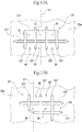
Fig. 8A is a front view showing the embodiment of the resin-made container according to the present invention. -
Fig. 8B is a side view of the resin-made container of the embodiment. -
Fig. 9A is a cross-sectional view of a projection of the resin-made container of the embodiment. -
Fig. 9B is a plan view of a part of the projection of the resin-made container of the embodiment. -
Fig. 10A is a plan view showing a shape of a recess of one flat area of the resin-made container of the embodiment. -
Fig. 10B is a plan view showing a shape of a recess of the other flat area of the resin-made container of the embodiment. -
Fig. 11A is a plan view showing a shape of a recess of a flat area of a resin-made container of another embodiment. -
Fig. 11B is a plan view showing a shape of a recess of a flat area of a resin-made container of still another embodiment. -
Fig. 12A is a plan view showing a shape of a recess of a flat area of a resin-made container of still another embodiment. -
Fig. 12B is a plan view showing a shape of a recess of a flat area of a resin-made container of still another embodiment. - An embodiment of the present invention will be described below by referring to
Figs. 1A to 10B . - As shown in
Figs. 1A to 7B , a resin-madecontainer 1 according to this embodiment includes acontainer body 2 formed by using a synthetic resin so as to form an internal space R for accommodating an article, and a cap body (not shown) to be attached to thecontainer body 2. The article to be accommodated in thecontainer body 2 is not particularly limited and includes those having fluidity such as a liquid, a powder body and the like (drinking water, tea, fruit juice, coffee, cocoa, soft drink, alcoholic drink, milk beverage, soup, sauce, soy sauce, salt, pepper, mayonnaise, ketchup and the like, for example). - Moreover, a capacity of the resin-made container 1 (container body 2) is not particularly limited but can be selected as appropriate in accordance with a type of the article to be accommodated and includes those with a relatively small capacity by the unit of several milliliters to the unit of several hundred milliliters to those with a relatively large capacity by the unit of several liters (specifically 1 liter to 2 liters).
- The
container body 2 is formed by using a synthetic resin. The synthetic resin includes, but is not particularly limited to, materials mainly made of thermoplastic resin such as polyethylene, polypropylene, or polyethylene terephthalate. A method for molding thecontainer body 2 is not particularly limited but can be a publicly-known molding method including, for example, a biaxial stretching blow molding method. The cap body may be formed by using the same synthetic resin as that of thecontainer body 2 or may be formed by using a different material. - In the following description, a
recess 2f of the container body 2 (therecess 2f will be described later) are schematically shown with lines inFigs. 8A and 8B . Also,first grooves 2k andsecond grooves 2m of the container body 2 (thefirst grooves 2k and thesecond grooves 2m will be described later) are schematically shown with lines inFigs. 8A and 8B . - As shown in
Figs. 8A and 8B , thecontainer body 2 includes atubular portion 2a formed in a tubular shape and abottom portion 2b formed so as to close one end in the direction of an axis (a virtual line) L1 in thetubular portion 2a. The internal space R includes a space surrounded by thetubular portion 2a and thebottom portion 2b. - The
tubular portion 2a includes aneck part 2c formed in the other end in the direction of the axis L1 so as to form an opening communicating with the internal space R, ashoulder part 2d formed so as to expand as it advances from theneck part 2c toward thebottom portion 2b side, and abody part 2e formed to extend from theshoulder part 2d toward thebottom portion 2b and connect to thebottom portion 2b. In other words, thetubular portion 2a includes theneck part 2c formed in the other end in the direction of the axis L1 so as to form an opening communicating with the internal space R, theshoulder part 2d formed so as to expand as it advances from theneck part 2c toward thebottom portion 2b, and thebody part 2e formed to extend from theshoulder part 2d toward thebottom portion 2b and connect to thebottom portion 2b. Theneck part 2c is configured to enable the cap body to be mounted (specifically, screwed) thereto. With the cap body mounted (specifically, screwed) to theneck part 2c, the internal space R is configured to be tightly sealed. - The
body part 2e is configured such that a section orthogonal to the direction of the axis L1 has a quadrilateral shape (specifically, a rectangular shape). Thebody part 2e includes a pair offirst side walls 21a that form a pair of long sides of a rectangular shape in the cross section, and a pair ofsecond side walls 22a that constitute a pair of short sides of a rectangular shape in the cross section. That is, the pair of thefirst side walls 21a are formed to oppose each other while the pair of thesecond side walls 22a are also formed to oppose each other. - The
body part 2e includes a rib-shapedportion 21e formed around the entire periphery thereof with the axis L1 as a center, a bulgingportion 22e formed so as to further bulge to the outer side of the container body 2 (thetubular portion 2a) than the rib-shapedportion 21e, and a flat area (flat portion) formed without being curved to the outer side of the container body 2 (specifically, along the axis L1) 23e. In other words, theflat area 23e is an area having a linear shape when viewed along the axis L1. - The rib-shaped
portion 21e is formed in the center of thebody part 2e in the direction of the axis L1. Also, the rib-shapedportion 21e includes a plurality ofprojections 24e formed at intervals in the direction of the axis L1. Each of theprojections 24e is formed continuously (i.e., annularly) around the entire periphery of thebody part 2e with the axis L1 as a center. - As shown in
Fig. 9A , theprojection 24e includes afirst area 2g of which a surface on one side contacts the internal space R, andsecond areas 2h that extend respectively from ends of thefirst area 2g toward the surface on the one side of thefirst area 2g (i.e. the surface side that contacts the internal space R). Specifically, theprojection 24e includes thefirst area 2g, and a pair of thesecond areas 2h respectively extending from the opposite ends in thefirst area 2g (specifically, the ends opposed in the direction of the axis L1). - The
second areas 2h are formed on an outer side of an area of a cast shadow produced in the internal space R by projection of light on thefirst area 2g on to the internal space R side of thefirst area 2g. Specifically, thesecond areas 2h are formed to lie on the outside of thefirst area 2g while extending respectively from the ends of thefirst area 2g toward the surface on the one side of thefirst area 2g. The pair of thesecond areas 2h are formed so that a distance therebetween is widened as they advance from thefirst area 2g to the internal space R. Thesecond areas 2h each include ashoulder area 2i formed on thefirst area 2g side and connected to the corresponding end of thefirst area 2g, and an internal-space side area 2j formed closer to the internal space R than theshoulder area 2i. Theshoulder area 2i is formed so as to bulge (curve) toward the outer side of thecontainer body 2 while the internal-space side area 2j is formed having a flat plate shape. - Referring back to
Figs. 8A and 8B , theprojections 24e each include, as shown inFig. 8B , thefirst groove 2k extending in one direction (specifically, a direction crossing the axis L1) (hereinafter also referred to as the first direction), and thesecond grooves 2m extending in another direction crossing the first direction (specifically, a direction crossing the longitudinal direction of thefirst groove 2k) (hereinafter also referred to as the second direction) (specifically, formed along the axis L1). In this embodiment, thefirst groove 2k and thesecond grooves 2m are formed in an area constituting theprojection 24e in the pair of thesecond side walls 22a. - When the
container body 2 is placed on a flat surface so that the direction of the axis L1 is oriented vertically, thefirst groove 2k is arranged so as to cross (specifically, be orthogonal to) the vertical direction and thesecond grooves 2m are arranged along the vertical direction. Accordingly, in the description below, thefirst groove 2k is described as alateral groove 2k while thesecond grooves 2m asvertical grooves 2m. - The
lateral groove 2k is formed linearly in thefirst area 2g. A length of thelateral groove 2k is not particularly limited, but in this embodiment, it is set to allow thelateral groove 2k to lie within an area visually observable when thecontainer body 2 is viewed from the direction orthogonal to the axis L1. - As shown in
Fig. 9B , thevertical grooves 2m are formed so as to respectively overlap virtual lines L2 that extend in the second direction crossing (specifically, orthogonal to) the first direction (i.e. along the axis L1). The virtual line L2 is set so as to cross thelateral groove 2k in thefirst area 2g. That is, thevertical grooves 2m are formed so as to cross thelateral groove 2k in thefirst area 2g. Thevertical grooves 2m are formed to extend continuously from inside of thefirst area 2g to insides of thesecond areas 2h. That is, thevertical grooves 2m are formed so as to cross the connection positions between thefirst area 2g and thesecond areas 2h along the second direction. In this embodiment, thevertical grooves 2m are formed so as to cross theshoulder area 2i along the virtual line L2 (i.e. along the second direction). - Each of the
vertical grooves 2m formed on a corresponding one of the virtual lines L2 is formed to extend continuously from the inside of thefirst area 2g to each of the insides of the pair of thesecond areas 2h. Specifically, thevertical groove 2m is formed to extend continuously so as to cross thefirst area 2g from the inside of one of thesecond areas 2h to the inside of the othersecond area 2h. As a result, thevertical groove 2m is configured so as to cross thelateral groove 2k in thefirst area 2g. Thevertical grooves 2m are formed in plural at intervals in the first direction (specifically, in the longitudinal direction of thelateral groove 2k). That is, in this embodiment, a plurality of thevertical grooves 2m cross the onelateral groove 2k. - Referring back to
Figs. 8A and 8B , the bulgingportions 22e are formed in pair at both ends of thebody part 2e in the direction of the axis L1. The rib-shapedportion 21e and theflat areas 23e are formed between the pair of the bulgingportions 22e. The bulgingportions 22e are formed so as to further bulge to an outer side of thebody part 2e than the rib-shapedportion 21e and theflat areas 23e. As a result, when the label (not shown) is wrapped around thetubular portion 2a so as to cover an area between the pair of the bulgingportions 22e (i.e. the rib-shapedportion 21e and theflat areas 23e), the pair of the bulgingportions 22e hold the label therebetween in the direction of the axis L1, thereby preventing the label from being displaced in the direction of the axis L1. - The
flat area 23e is formed between the rib-shapedportion 21e and the bulgingportion 22e. In this embodiment, a pair of theflat areas 23e are formed between the rib-shapedportion 21e and the pair of the bulgingportions 22e. Specifically, oneflat area 23e is formed between one bulgingportion 22e formed on theneck part 2c side of thecontainer body 2 and the rib-shapedportion 21e, while the otherflat area 23e is formed between the bulgingportion 22e formed on thebottom portion 2b side of thecontainer body 2 and the rib-shapedportion 21e. Theflat areas 23e are formed in the pair of thefirst side walls 21a constituting thebody part 2e. - The
flat area 23e includes at least onerecess 2f formed so as to enclose a certain area in theflat area 23e. Therecess 2f is formed in each of the pair of theflat areas 23e. As shown inFigs. 10A and 10B , therecess 2f formed in each of theflat areas 23e includes afirst recess portion 21f having a groove shape extending in the first direction (specifically, the direction crossing the axis L1), andsecond recess portions 22f each having a groove shape extending in the second direction crossing the first direction (specifically, the direction along the axis L1). - As shown in
Fig. 10A , thefirst recess portion 21f and thesecond recess portion 22f in the oneflat area 23e (specifically, formed on theneck part 2c side of the container body 2) are formed so as to cross each other. Specifically, a plurality of thefirst recess portions 21f and a plurality of thesecond recess portions 22f are each formed to cross each other (i.e. in a grid pattern). In this embodiment, twofirst recess portions 21f formed at an interval in the direction of the axis L1 and foursecond recess portions 22f formed at intervals in the direction orthogonal to the axis L1 are configured to cross each other (i.e. in a grid pattern). - Specifically, one
first recess portion 21f (specifically, formed on thebottom portion 2b side of the container body 2) is configured to cross the foursecond recess portions 22f at positions inside the both ends thereof. The otherfirst recess portion 21f (specifically, formed on theneck part 2c side of the container body 2) is configured to cross the twosecond recess portions 22f at the both ends thereof and cross the other twosecond recess portions 22f at positions inside the both ends thereof. - The
second recess portions 22f are configured to cross the onefirst recess portion 21f at positions inside both ends thereof. Out of the foursecond recess portions 22f, the two outersecond recess portions 22f are configured to cross the otherfirst recess portion 21f at an end thereof while the two innersecond recess portions 22f are configured to cross the otherfirst recess portion 21f at positions inside the both ends thereof. - As shown in
Fig. 10B , thefirst recess portion 21f and thesecond recess portion 22f in the otherflat area 23e (specifically, formed on thebottom portion 2b side of the container body 2) are formed so as to cross each other. Specifically, a plurality of thefirst recess portions 21f and a plurality of thesecond recess portions 22f are formed to cross each other (i.e. in a grid pattern). In this embodiment, twofirst recess portions 21f formed at an interval in the direction of the axis L1 and threesecond recess portions 22f formed at intervals in the direction orthogonal to the axis L1 are configured to cross each other (i.e. in a grid pattern). - Specifically, one
first recess portion 21f (specifically, formed on thebottom portion 2b side of the container body 2) is configured to cross two adjacentsecond recess portions 22f at positions inside the both ends thereof. The otherfirst recess portion 21f (specifically, formed on theneck part 2c side of the container body 2) is configured to cross thesecond recess portions 22f at positions inside the both ends thereof. - The
second recess portions 22f are configured to cross the otherfirst recess portion 21f at positions inside both ends thereof. One of the two adjacentsecond recess portions 22f is configured to cross the onefirst recess portion 21f at a position inside the both ends thereof while the other of the two adjacentsecond recess portions 22f is configured to cross the onefirst recess portion 21f at an end thereof. Thesecond recess portion 22f other than the two adjacentsecond recess portions 22f is configured not to cross the onefirst recess portion 21f. - With the
flat area 23e having therecess 2f as aforementioned, areas enclosed by therecess 2f (specifically, areas enclosed by thefirst recess portions 21f and thesecond recess portions 22f) are formed in theflat area 23e. Specifically, in the oneflat area 23e (specifically, formed on theneck part 2c side of the container body 2), enclosed areas A1 that are enclosed by the two adjacentfirst recess portions 21f and the two adjacentsecond recess portions 22f, and enclosed areas A2 that are enclosed by the onefirst recess portion 21f and the two adjacentsecond recess portions 22f (i.e. areas partially enclosed by therecess 2f) (in more detail, U-shaped areas) are formed, as shown inFig. 10A . - In the other
flat area 23e, the enclosed areas A1 that are enclosed by the two adjacentfirst recess portions 21f and the two adjacentsecond recess portions 22f, the enclosed areas A2 that are enclosed by the onefirst recess portion 21f and the two adjacentsecond recess portions 22f (i.e. areas partially enclosed by therecess 2f) (in more detail, U-shaped areas), and an enclosed area A3 that is enclosed by the twofirst recess portions 21f and the onesecond recess portion 22f (i.e. an area partially enclosed by therecess 2f) (in more detail, a U-shaped area) are formed. The total area of the enclosed areas A1 and A2 (or the total area of the enclosed areas A1, A2, and A3) is preferably within a range of 30% to 80% of the entire area of the one (or the other)flat area 23e, or preferably within a range of 50% to 70% thereof. - As described above, the resin-made container according to the present invention allows a label to be optimally wrapped around the
container body 2 by suppressing theflat area 23e of thecontainer body 2 from being deformed. - That is, the
recess 2f formed so as to enclose the certain area in theflat area 23e allows the label (not shown) to be optimally wrapped around thetubular portion 2a so as to cover theflat area 23e. - Specifically, the
flat area 23e having therecess 2f formed so as to enclose the certain area therein is higher in rigidity than theflat area 23e without therecess 2f. This configuration suppresses theflat area 23e from bulging toward the outer side of thecontainer body 2 when thecontainer body 2 is subjected to external force. As a result, a peripheral dimension of thetubular portion 2a including theflat area 23e (hereinafter also referred to as an outer peripheral dimension) remains unchanged before and after thecontainer body 2 is subjected to external force, thus enabling a label formed to correspond to the outer peripheral dimension of thetubular portion 2a to be optimally (tightly) wrapped around thetubular portion 2a. - Additionally, this configuration suppresses deformation of the
container body 2 that causes theflat area 23e to bulge, thereby suppressing thecontainer body 2 from being filled with an article exceeding the prescribed amount (i.e. suppressing overfilling). This configuration as a result prevents the article (particularly a liquid article) in thecontainer body 2 from unintentionally spurting out of the container body 2 (particularly, spurting after filling by the gravity method). - The
recess 2f includes thefirst recess portions 21f having a groove shape extending in the first direction and thesecond recess portions 22f having a groove shape extending in the second direction crossing the first direction, and thefirst recess portions 21f and thesecond recess portions 22f are formed in a grid pattern, suppressing deformation of theflat area 23e in a more effective manner. As a result, the label can be more optimally wrapped around thecontainer body 2. - The
flat area 23e formed between at least one bulgingportion 22e and the rib-shapedportion 21e is more likely deformed (or more likely bulges) than that formed in a different position; however, therecess 2f included in theflat area 23e more effectively suppresses bulging of theflat area 23e toward the outer side of thecontainer body 2. As a result, the label can be more optimally wrapped around thecontainer body 2. - The
projections 24e configured as aforementioned are deformed toward the internal space R when an area including thelateral groove 2k and the plurality of thevertical grooves 2m in eachprojection 24e (hereinafter also referred to as a pressed area) is pressed, but is restored to the original state by removing force exerted by the pressing. This configuration can prevent theprojections 24e from being permanently deformed by pressing. - Specifically, by providing the
vertical grooves 2m formed to extend continuously from the inside of thefirst area 2g to the insides of thesecond areas 2h, a connection portion between thefirst area 2g and thesecond area 2h is crossed by thevertical grooves 2m along the second direction (specifically, the axis L1). As a result, portions overlapping thevertical grooves 2m in the connection portion between thefirst area 2g and thesecond area 2h are deformed more easily toward the internal space R along thevertical grooves 2m. A plurality of suchvertical grooves 2m are formed at intervals in the first direction (specifically, the direction orthogonal to the axis L1), and thus theprojection 24e becomes flexible with respect to deformation (in other words, deformation along the virtual line L2) along the second (specifically, the axis L1) direction (that is, the direction along thevertical grooves 2m). - Since the
lateral groove 2k is formed so as to cross the virtual lines L2 in thefirst area 2g, theprojection 24e has rigidity against deformation toward the internal space R along the virtual lines L2 (in other words, along thevertical grooves 2m). - As described above, since the
projection 24e has both flexibility and rigidity to deformation along the second (specifically, the axis L1) direction, even when the pressed area is pressed and deformed, the pressed area is restored to the state before the deformation by removing the force exerted by the pressing. As a result, permanent deformation of theprojection 24e caused by pressing can be prevented. - Since the
projection 24e includes thefirst area 2g and the pair ofsecond areas 2h extending respectively from the ends opposed in the second (specifically, the axis L1) direction in thefirst area 2g, the connection portions of thefirst area 2g with thesecond area 2h are located at the positions opposed in the second (specifically, the axis L1) direction. Since thevertical groove 2m formed on each virtual line L2 is formed to extend continuously from the inside of thefirst area 2g to the insides of the pair ofsecond areas 2h, thevertical groove 2m crosses the connection portions of thefirst area 2g with thesecond areas 2h along the second (specifically, the axis L1) direction. As a result, theprojection 24e becomes deformable more easily along thevertical groove 2m (specifically, along the axis L1), making its flexibility higher. Thus, since theprojection 24e is more easily restored from the deformed state by pressing to the state before the deformation, occurrence of permanent deformation in theprojection 24e can be prevented more reliably. - The
vertical groove 2m formed on each virtual line L2 is formed to extend continuously so as to cross thefirst area 2g from the inside of one of thesecond areas 2h to the inside of the othersecond area 2h, and thevertical groove 2m crosses thelateral groove 2k; thus, theprojection 24e becomes deformable more easily along thevertical groove 2m (specifically, along the axis L1), and its flexibility becomes higher. Since thevertical groove 2m and thelateral groove 2k cross each other, theprojection 24e has higher rigidity to deformation along thevertical groove 2m. As a result, theprojection 24e having been deformed by pressing as described above is restored to the state more reliably before the deformation, thereby preventing theprojection 24e from permanent deformation more reliably. - The resin-made container according to the present invention is not limited to the aforementioned embodiment but can be subjected to various changes without departing from the gist of the present invention. Moreover, configurations, methods or the like of the aforementioned embodiments may be arbitrarily employed and combined (the configuration, the method or the like according to one embodiment may be applied to the configuration, the method or the like of another embodiment), and furthermore, it is needless to say that configurations, methods or the like according to various modified examples described below may be arbitrarily selected and employed for the configurations, methods, or the like according to the aforementioned embodiment.
- The aforementioned embodiment is described by taking, for example, the case where the
first recess portions 21f having a groove shape and thesecond recess portions 22f having a groove shape are formed so as to cross each other, without limitation thereto. As shown inFig. 11A , thefirst recess portions 21f and thesecond recess portions 22f may be formed so as not to cross each other, for example. In such a case, enclosed areas A1' and A2' non-continuously enclosed by thefirst recess portions 21f and thesecond recess portions 22f are formed. - The aforementioned embodiment is described by taking the case where the
recess 2f is formed in a grid pattern, without limitation thereto. For example, as shown inFig. 11B ,recess 2f' may be formed with recess portions having an annular shape (hereinafter also referred to as annular recess portions) 23f formed so as to cross each other. In such a case, enclosed areas A4 enclosed by theannular recess portions 23f are formed. Alternatively, as shown inFig. 12A , recesses 2f" may be formed with one group ofannular recess portions 24f and another group of annular recess portions 25 arranged inside thereof. In such a case, enclosed areas A5 each are formed between the outerannular recess portion 24f and the innerannular recess portion 25f, and enclosed areas A6 each are also formed inside the innerannular recess portion 25f. Further alternatively, as shown inFig. 12B ,recess 2f'" may be formed with two recess portions having a wave shape (hereinafter also referred to as wave-shaped recess portions) 26f configured to cross each other. In such a case, enclosed areas A7 are formed between the two wave-shapedrecess portions 26f. - The aforementioned embodiment is described by taking the case where the
first recess portions 21f and thesecond recess portion 22f are formed linearly, without limitation thereto. For example, one or either of thefirst recess portion 21f and thesecond recess portion 22f may be formed in such a shape as a wave shape. - The aforementioned embodiment is described by taking the case where the resin-made
container 1 includes thecontainer body 2 and the cap body, without limitation thereto. For example, the resin-made container may include only thecontainer body 2. -
- 1: Resin-made container
- 2: Container body
- 2a: Tubular portion
- 21a, 22a: Side wall
- 2b: Bottom portion
- 2c: Neck part
- 2d: Shoulder part
- 2e: Body part
- 21e: Rib-shaped portion
- 22e: Bulging portion
- 23e: Flat area
- 24e: Projection
- 2f, 2f', 2f", 2f"': Recess
- 21f: First recess portion
- 22f: Second recess portion
- 23f, 24f, 25f: Annular recess portion
- 26f: Wave-shaped recess portion
- 2g: First area
- 2h: Second area
- 2i: Shoulder area
- 2j: Internal-space side area
- 2k: First groove
- 2m: Second groove
- A1, A2, A3, A4, A5, A6, A7: Enclosed area
- L1: Axis
- L2: Virtual line
- R: Internal space
Claims (5)
- A resin-made container comprising: a container body that is made of resin having a tubular portion formed in a tubular shape and configured to allow a label to be wrapped therearound, and a bottom portion closing one end of the tubular portion in a direction of an axis of the tubular portion,
wherein the tubular portion includes a flat area in an area covered by the label, and
wherein the resin-made container includes at least one recess formed so as to enclose a certain area in the flat area. - The resin-made container according to claim 1, wherein the recess comprises a first recess portion having a groove shape extending in one direction and a second recess portion having a groove shape extending in an other direction crossing the one direction.
- The resin-made container according to claim 2, wherein the recess comprises a plurality of the first recess portions and a plurality of the second recess portions that are formed in a grid pattern.
- The resin-made container according to any one of claims 1 to 3, wherein the tubular portion includes a rib-shaped portion formed around the entire periphery with the axis of the tubular portion as a center, and a pair of bulging portions formed closer to both end sides in the direction of the axis than the rib-shaped portion and further bulge to an outer side of the container body than the rib-shaped portion, and the flat area is formed between at least one of the bulging portions and the rib-shaped portion.
- The resin-made container according to claim 4,
wherein the rib-shaped portion 21e comprises a plurality of projections formed in an annular shape in a peripheral direction of the tubular portion and formed at intervals in the direction of the axis of the tubular portion,
wherein each of the plurality of projection comprises a first area of which a surface on one side contacts an internal space formed inside the tubular portion, and second areas extending respectively from ends of the first area toward the surface on the one side of the first area and formed on an outer side of an area of a cast shadow produced in the internal space by projection of light on the first area, and include a first groove formed in the first area so as to extend in one direction and a plurality of second groove formed so as to extend in an other direction crossing the one direction, and
wherein the plurality of second grooves are formed to extend continuously from an inside of the first area to insides of the second areas so as to respectively overlap virtual lines crossing the first groove in the first area, and formed at intervals in the one direction.
Applications Claiming Priority (2)
| Application Number | Priority Date | Filing Date | Title |
|---|---|---|---|
| JP2015141200A JP6700681B2 (en) | 2015-07-15 | 2015-07-15 | Resin container |
| PCT/JP2016/070823 WO2017010545A1 (en) | 2015-07-15 | 2016-07-14 | Resinous container |
Publications (3)
| Publication Number | Publication Date |
|---|---|
| EP3323746A1 true EP3323746A1 (en) | 2018-05-23 |
| EP3323746A4 EP3323746A4 (en) | 2019-04-03 |
| EP3323746B1 EP3323746B1 (en) | 2020-09-09 |
Family
ID=57757920
Family Applications (1)
| Application Number | Title | Priority Date | Filing Date |
|---|---|---|---|
| EP16824525.6A Active EP3323746B1 (en) | 2015-07-15 | 2016-07-14 | Resinous container |
Country Status (4)
| Country | Link |
|---|---|
| EP (1) | EP3323746B1 (en) |
| JP (1) | JP6700681B2 (en) |
| ES (1) | ES2829026T3 (en) |
| WO (1) | WO2017010545A1 (en) |
Family Cites Families (11)
| Publication number | Priority date | Publication date | Assignee | Title |
|---|---|---|---|---|
| US7469796B2 (en) * | 2003-03-12 | 2008-12-30 | Constar International Inc. | Container exhibiting improved top load performance |
| JP4925000B2 (en) * | 2005-12-27 | 2012-04-25 | 株式会社吉野工業所 | Synthetic resin square housing |
| JP5362271B2 (en) * | 2008-07-03 | 2013-12-11 | 北海製罐株式会社 | Plastic bottle |
| US8727152B2 (en) * | 2009-12-29 | 2014-05-20 | Amcor Limited | Hot-fill container having flat panels |
| JP5589535B2 (en) * | 2010-04-30 | 2014-09-17 | 東洋製罐株式会社 | Plastic container |
| US9415894B2 (en) * | 2010-06-30 | 2016-08-16 | Amcor Limited | Pressure resistant vacuum/label panel |
| JP2013023227A (en) * | 2011-07-15 | 2013-02-04 | Dainippon Printing Co Ltd | Heat labile molded plastic bottle |
| JP5893401B2 (en) * | 2011-12-28 | 2016-03-23 | 大日本印刷株式会社 | Plastic bottle |
| JP2013154907A (en) * | 2012-01-30 | 2013-08-15 | Yoshino Kogyosho Co Ltd | Bottle |
| CN105667925B (en) * | 2012-02-29 | 2018-03-30 | 株式会社吉野工业所 | Bottle |
| JP6240499B2 (en) * | 2013-12-27 | 2017-11-29 | サントリーホールディングス株式会社 | Bottle container |
-
2015
- 2015-07-15 JP JP2015141200A patent/JP6700681B2/en active Active
-
2016
- 2016-07-14 ES ES16824525T patent/ES2829026T3/en active Active
- 2016-07-14 EP EP16824525.6A patent/EP3323746B1/en active Active
- 2016-07-14 WO PCT/JP2016/070823 patent/WO2017010545A1/en active Application Filing
Also Published As
| Publication number | Publication date |
|---|---|
| JP6700681B2 (en) | 2020-05-27 |
| WO2017010545A1 (en) | 2017-01-19 |
| EP3323746B1 (en) | 2020-09-09 |
| ES2829026T3 (en) | 2021-05-28 |
| JP2017019555A (en) | 2017-01-26 |
| EP3323746A4 (en) | 2019-04-03 |
Similar Documents
| Publication | Publication Date | Title |
|---|---|---|
| JP6342112B2 (en) | Resin container | |
| EP2653400B1 (en) | Plastic container | |
| US8727154B2 (en) | Synthetic resin bottle | |
| US20100183776A1 (en) | Water bottle with dosage in a blister pack | |
| EP3483085A1 (en) | Sheet material container | |
| US20100006580A1 (en) | Thermoplastic container, in particular a bottle, having a partially prismatic triangular body | |
| CN104781151A (en) | Reclosable pour-out element for packaging, mandrel of a rotatable mandrel wheel in a packaging machine for receiving such a pour-out element and combination of pour-out element and mandrel | |
| US20110097453A1 (en) | Container Assembly for a Potable Liquid and Method for Manufacturing Same | |
| EP3323746B1 (en) | Resinous container | |
| US9731852B2 (en) | Water bottle with dosage in a blister pack | |
| JP2004323100A (en) | Synthetic resin-made bottle container equipped with depressurization absorption wall | |
| JP6353947B2 (en) | Resin container | |
| CA2945613C (en) | Closure cap for a substantially cylindrical vessel | |
| JP3169856U (en) | Pouch with cap | |
| JP2019189341A (en) | Beverage container | |
| JP6886815B2 (en) | Bottle | |
| EP3088317B1 (en) | Bottle container | |
| JP6249595B2 (en) | Resin container | |
| JP5693053B2 (en) | Overcap for container | |
| JP2018162095A (en) | Container made of resin | |
| EP3216710B1 (en) | Resin-made container | |
| JP6756100B2 (en) | Synthetic resin container | |
| JP2008030850A (en) | Synthetic resin bottle | |
| JP2008030842A (en) | Synthetic resin bottle | |
| JP2016124615A (en) | Ptp package |
Legal Events
| Date | Code | Title | Description |
|---|---|---|---|
| STAA | Information on the status of an ep patent application or granted ep patent |
Free format text: STATUS: THE INTERNATIONAL PUBLICATION HAS BEEN MADE |
|
| PUAI | Public reference made under article 153(3) epc to a published international application that has entered the european phase |
Free format text: ORIGINAL CODE: 0009012 |
|
| STAA | Information on the status of an ep patent application or granted ep patent |
Free format text: STATUS: REQUEST FOR EXAMINATION WAS MADE |
|
| 17P | Request for examination filed |
Effective date: 20180109 |
|
| AK | Designated contracting states |
Kind code of ref document: A1 Designated state(s): AL AT BE BG CH CY CZ DE DK EE ES FI FR GB GR HR HU IE IS IT LI LT LU LV MC MK MT NL NO PL PT RO RS SE SI SK SM TR |
|
| AX | Request for extension of the european patent |
Extension state: BA ME |
|
| DAV | Request for validation of the european patent (deleted) | ||
| DAX | Request for extension of the european patent (deleted) | ||
| A4 | Supplementary search report drawn up and despatched |
Effective date: 20190301 |
|
| RIC1 | Information provided on ipc code assigned before grant |
Ipc: B65D 1/02 20060101AFI20190225BHEP Ipc: B65D 1/46 20060101ALI20190225BHEP |
|
| GRAP | Despatch of communication of intention to grant a patent |
Free format text: ORIGINAL CODE: EPIDOSNIGR1 |
|
| STAA | Information on the status of an ep patent application or granted ep patent |
Free format text: STATUS: GRANT OF PATENT IS INTENDED |
|
| INTG | Intention to grant announced |
Effective date: 20200213 |
|
| GRAS | Grant fee paid |
Free format text: ORIGINAL CODE: EPIDOSNIGR3 |
|
| GRAA | (expected) grant |
Free format text: ORIGINAL CODE: 0009210 |
|
| STAA | Information on the status of an ep patent application or granted ep patent |
Free format text: STATUS: THE PATENT HAS BEEN GRANTED |
|
| AK | Designated contracting states |
Kind code of ref document: B1 Designated state(s): AL AT BE BG CH CY CZ DE DK EE ES FI FR GB GR HR HU IE IS IT LI LT LU LV MC MK MT NL NO PL PT RO RS SE SI SK SM TR |
|
| REG | Reference to a national code |
Ref country code: GB Ref legal event code: FG4D |
|
| REG | Reference to a national code |
Ref country code: AT Ref legal event code: REF Ref document number: 1311295 Country of ref document: AT Kind code of ref document: T Effective date: 20200915 Ref country code: CH Ref legal event code: EP |
|
| REG | Reference to a national code |
Ref country code: IE Ref legal event code: FG4D |
|
| REG | Reference to a national code |
Ref country code: DE Ref legal event code: R096 Ref document number: 602016043819 Country of ref document: DE |
|
| REG | Reference to a national code |
Ref country code: LT Ref legal event code: MG4D |
|
| PG25 | Lapsed in a contracting state [announced via postgrant information from national office to epo] |
Ref country code: FI Free format text: LAPSE BECAUSE OF FAILURE TO SUBMIT A TRANSLATION OF THE DESCRIPTION OR TO PAY THE FEE WITHIN THE PRESCRIBED TIME-LIMIT Effective date: 20200909 Ref country code: NO Free format text: LAPSE BECAUSE OF FAILURE TO SUBMIT A TRANSLATION OF THE DESCRIPTION OR TO PAY THE FEE WITHIN THE PRESCRIBED TIME-LIMIT Effective date: 20201209 Ref country code: HR Free format text: LAPSE BECAUSE OF FAILURE TO SUBMIT A TRANSLATION OF THE DESCRIPTION OR TO PAY THE FEE WITHIN THE PRESCRIBED TIME-LIMIT Effective date: 20200909 Ref country code: LT Free format text: LAPSE BECAUSE OF FAILURE TO SUBMIT A TRANSLATION OF THE DESCRIPTION OR TO PAY THE FEE WITHIN THE PRESCRIBED TIME-LIMIT Effective date: 20200909 Ref country code: SE Free format text: LAPSE BECAUSE OF FAILURE TO SUBMIT A TRANSLATION OF THE DESCRIPTION OR TO PAY THE FEE WITHIN THE PRESCRIBED TIME-LIMIT Effective date: 20200909 Ref country code: BG Free format text: LAPSE BECAUSE OF FAILURE TO SUBMIT A TRANSLATION OF THE DESCRIPTION OR TO PAY THE FEE WITHIN THE PRESCRIBED TIME-LIMIT Effective date: 20201209 Ref country code: GR Free format text: LAPSE BECAUSE OF FAILURE TO SUBMIT A TRANSLATION OF THE DESCRIPTION OR TO PAY THE FEE WITHIN THE PRESCRIBED TIME-LIMIT Effective date: 20201210 |
|
| REG | Reference to a national code |
Ref country code: AT Ref legal event code: MK05 Ref document number: 1311295 Country of ref document: AT Kind code of ref document: T Effective date: 20200909 |
|
| REG | Reference to a national code |
Ref country code: NL Ref legal event code: MP Effective date: 20200909 |
|
| PG25 | Lapsed in a contracting state [announced via postgrant information from national office to epo] |
Ref country code: PL Free format text: LAPSE BECAUSE OF FAILURE TO SUBMIT A TRANSLATION OF THE DESCRIPTION OR TO PAY THE FEE WITHIN THE PRESCRIBED TIME-LIMIT Effective date: 20200909 Ref country code: LV Free format text: LAPSE BECAUSE OF FAILURE TO SUBMIT A TRANSLATION OF THE DESCRIPTION OR TO PAY THE FEE WITHIN THE PRESCRIBED TIME-LIMIT Effective date: 20200909 Ref country code: RS Free format text: LAPSE BECAUSE OF FAILURE TO SUBMIT A TRANSLATION OF THE DESCRIPTION OR TO PAY THE FEE WITHIN THE PRESCRIBED TIME-LIMIT Effective date: 20200909 |
|
| PG25 | Lapsed in a contracting state [announced via postgrant information from national office to epo] |
Ref country code: CZ Free format text: LAPSE BECAUSE OF FAILURE TO SUBMIT A TRANSLATION OF THE DESCRIPTION OR TO PAY THE FEE WITHIN THE PRESCRIBED TIME-LIMIT Effective date: 20200909 Ref country code: PT Free format text: LAPSE BECAUSE OF FAILURE TO SUBMIT A TRANSLATION OF THE DESCRIPTION OR TO PAY THE FEE WITHIN THE PRESCRIBED TIME-LIMIT Effective date: 20210111 Ref country code: RO Free format text: LAPSE BECAUSE OF FAILURE TO SUBMIT A TRANSLATION OF THE DESCRIPTION OR TO PAY THE FEE WITHIN THE PRESCRIBED TIME-LIMIT Effective date: 20200909 Ref country code: EE Free format text: LAPSE BECAUSE OF FAILURE TO SUBMIT A TRANSLATION OF THE DESCRIPTION OR TO PAY THE FEE WITHIN THE PRESCRIBED TIME-LIMIT Effective date: 20200909 Ref country code: SM Free format text: LAPSE BECAUSE OF FAILURE TO SUBMIT A TRANSLATION OF THE DESCRIPTION OR TO PAY THE FEE WITHIN THE PRESCRIBED TIME-LIMIT Effective date: 20200909 |
|
| REG | Reference to a national code |
Ref country code: ES Ref legal event code: FG2A Ref document number: 2829026 Country of ref document: ES Kind code of ref document: T3 Effective date: 20210528 |
|
| PG25 | Lapsed in a contracting state [announced via postgrant information from national office to epo] |
Ref country code: AT Free format text: LAPSE BECAUSE OF FAILURE TO SUBMIT A TRANSLATION OF THE DESCRIPTION OR TO PAY THE FEE WITHIN THE PRESCRIBED TIME-LIMIT Effective date: 20200909 Ref country code: AL Free format text: LAPSE BECAUSE OF FAILURE TO SUBMIT A TRANSLATION OF THE DESCRIPTION OR TO PAY THE FEE WITHIN THE PRESCRIBED TIME-LIMIT Effective date: 20200909 Ref country code: IS Free format text: LAPSE BECAUSE OF FAILURE TO SUBMIT A TRANSLATION OF THE DESCRIPTION OR TO PAY THE FEE WITHIN THE PRESCRIBED TIME-LIMIT Effective date: 20210109 |
|
| REG | Reference to a national code |
Ref country code: DE Ref legal event code: R097 Ref document number: 602016043819 Country of ref document: DE |
|
| PG25 | Lapsed in a contracting state [announced via postgrant information from national office to epo] |
Ref country code: SK Free format text: LAPSE BECAUSE OF FAILURE TO SUBMIT A TRANSLATION OF THE DESCRIPTION OR TO PAY THE FEE WITHIN THE PRESCRIBED TIME-LIMIT Effective date: 20200909 |
|
| PLBE | No opposition filed within time limit |
Free format text: ORIGINAL CODE: 0009261 |
|
| STAA | Information on the status of an ep patent application or granted ep patent |
Free format text: STATUS: NO OPPOSITION FILED WITHIN TIME LIMIT |
|
| 26N | No opposition filed |
Effective date: 20210610 |
|
| PG25 | Lapsed in a contracting state [announced via postgrant information from national office to epo] |
Ref country code: DK Free format text: LAPSE BECAUSE OF FAILURE TO SUBMIT A TRANSLATION OF THE DESCRIPTION OR TO PAY THE FEE WITHIN THE PRESCRIBED TIME-LIMIT Effective date: 20200909 Ref country code: SI Free format text: LAPSE BECAUSE OF FAILURE TO SUBMIT A TRANSLATION OF THE DESCRIPTION OR TO PAY THE FEE WITHIN THE PRESCRIBED TIME-LIMIT Effective date: 20200909 |
|
| PG25 | Lapsed in a contracting state [announced via postgrant information from national office to epo] |
Ref country code: IT Free format text: LAPSE BECAUSE OF FAILURE TO SUBMIT A TRANSLATION OF THE DESCRIPTION OR TO PAY THE FEE WITHIN THE PRESCRIBED TIME-LIMIT Effective date: 20200909 |
|
| REG | Reference to a national code |
Ref country code: DE Ref legal event code: R119 Ref document number: 602016043819 Country of ref document: DE |
|
| REG | Reference to a national code |
Ref country code: CH Ref legal event code: PL |
|
| GBPC | Gb: european patent ceased through non-payment of renewal fee |
Effective date: 20210714 |
|
| PG25 | Lapsed in a contracting state [announced via postgrant information from national office to epo] |
Ref country code: MC Free format text: LAPSE BECAUSE OF FAILURE TO SUBMIT A TRANSLATION OF THE DESCRIPTION OR TO PAY THE FEE WITHIN THE PRESCRIBED TIME-LIMIT Effective date: 20200909 |
|
| REG | Reference to a national code |
Ref country code: BE Ref legal event code: MM Effective date: 20210731 |
|
| PG25 | Lapsed in a contracting state [announced via postgrant information from national office to epo] |
Ref country code: LI Free format text: LAPSE BECAUSE OF NON-PAYMENT OF DUE FEES Effective date: 20210731 Ref country code: GB Free format text: LAPSE BECAUSE OF NON-PAYMENT OF DUE FEES Effective date: 20210714 Ref country code: DE Free format text: LAPSE BECAUSE OF NON-PAYMENT OF DUE FEES Effective date: 20220201 Ref country code: CH Free format text: LAPSE BECAUSE OF NON-PAYMENT OF DUE FEES Effective date: 20210731 |
|
| PG25 | Lapsed in a contracting state [announced via postgrant information from national office to epo] |
Ref country code: LU Free format text: LAPSE BECAUSE OF NON-PAYMENT OF DUE FEES Effective date: 20210714 |
|
| PG25 | Lapsed in a contracting state [announced via postgrant information from national office to epo] |
Ref country code: IE Free format text: LAPSE BECAUSE OF NON-PAYMENT OF DUE FEES Effective date: 20210714 Ref country code: BE Free format text: LAPSE BECAUSE OF NON-PAYMENT OF DUE FEES Effective date: 20210731 |
|
| PG25 | Lapsed in a contracting state [announced via postgrant information from national office to epo] |
Ref country code: HU Free format text: LAPSE BECAUSE OF FAILURE TO SUBMIT A TRANSLATION OF THE DESCRIPTION OR TO PAY THE FEE WITHIN THE PRESCRIBED TIME-LIMIT; INVALID AB INITIO Effective date: 20160714 |
|
| P01 | Opt-out of the competence of the unified patent court (upc) registered |
Effective date: 20230509 |
|
| PG25 | Lapsed in a contracting state [announced via postgrant information from national office to epo] |
Ref country code: NL Free format text: LAPSE BECAUSE OF NON-PAYMENT OF DUE FEES Effective date: 20200923 Ref country code: CY Free format text: LAPSE BECAUSE OF FAILURE TO SUBMIT A TRANSLATION OF THE DESCRIPTION OR TO PAY THE FEE WITHIN THE PRESCRIBED TIME-LIMIT Effective date: 20200909 |
|
| PGFP | Annual fee paid to national office [announced via postgrant information from national office to epo] |
Ref country code: FR Payment date: 20230620 Year of fee payment: 8 |
|
| PGFP | Annual fee paid to national office [announced via postgrant information from national office to epo] |
Ref country code: ES Payment date: 20230801 Year of fee payment: 8 |