EP3323676B1 - Arrangement for securing objects on a surface, in particular a loading floor of a cargo transport vehicle - Google Patents
Arrangement for securing objects on a surface, in particular a loading floor of a cargo transport vehicle Download PDFInfo
- Publication number
- EP3323676B1 EP3323676B1 EP17199391.8A EP17199391A EP3323676B1 EP 3323676 B1 EP3323676 B1 EP 3323676B1 EP 17199391 A EP17199391 A EP 17199391A EP 3323676 B1 EP3323676 B1 EP 3323676B1
- Authority
- EP
- European Patent Office
- Prior art keywords
- ring
- securing
- base
- housing
- support
- Prior art date
- Legal status (The legal status is an assumption and is not a legal conclusion. Google has not performed a legal analysis and makes no representation as to the accuracy of the status listed.)
- Active
Links
- 238000003466 welding Methods 0.000 claims description 3
- 230000000295 complement effect Effects 0.000 claims description 2
- 238000006073 displacement reaction Methods 0.000 description 2
- 230000001419 dependent effect Effects 0.000 description 1
- 230000004048 modification Effects 0.000 description 1
- 238000012986 modification Methods 0.000 description 1
- 238000000465 moulding Methods 0.000 description 1
Images


Classifications
-
- B—PERFORMING OPERATIONS; TRANSPORTING
- B60—VEHICLES IN GENERAL
- B60P—VEHICLES ADAPTED FOR LOAD TRANSPORTATION OR TO TRANSPORT, TO CARRY, OR TO COMPRISE SPECIAL LOADS OR OBJECTS
- B60P7/00—Securing or covering of load on vehicles
- B60P7/06—Securing of load
- B60P7/08—Securing to the vehicle floor or sides
- B60P7/0807—Attachment points
Definitions
- the invention relates to an arrangement for securing objects on a surface in particular of a loading floor of a cargo transport vehicle, of the type described in the preamble of claim 1.
- the invention aims to overcome these drawbacks.
- the securing arrangement according to the invention includes the characteristics which are set out in the characterizing part of claim 1.
- the stowage arrangements are intended to stow objects 3 on a loading surface 5, in particular of a loading floor of a cargo transport vehicle.
- the stowage arrangement 1 is mounted in a support structure 7 which, on the Figures 1 and 2 is a chassis which could extend along a lateral edge of the loading floor, i.e. the edge of the edge of the vehicle.
- the supporting structure could also be of any other appropriate nature, such as an IPN-shaped beam, as shown in the figure 14 .
- the lashing arrangement comprises a lashing ring 9 and a ring support 10 which is mounted in the chassis.
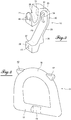
- the figure 1 shows the lashing arrangement in its working position, i.e. lashing of an object 3 on the surface of the floor 5 using a strap 14 by means of a hook 15 .
- the figure 2 shows the arrangement 1 in its retracted position in the chassis 7 flush with the loading floor surface 5.
- the lashing ring comprises a rounded stirrup part 16 for hooking the lashing means and a straight base 17 which connects the two ends of the stirrup.
- the base is cylindrical in shape and includes in its central area a flat part 19.
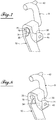
- the support for this ring as can be seen in particular on the figure 3 , consists of a yoke in the form of a band, the ends of which are configured as fixing lugs 21, 22 on a surface 24 of the carrying structure, which extends perpendicular to the loading floor, one 21 above the other 22 at a predetermined distance.
- the upper part of the yoke strip, which is adjacent to the loading floor is bent in the example shown by an angle of 180 degrees, forming at the top a semi-cylindrical housing 25 in which the cylindrical base of the ring can engage to allow pivoting of the ring in its stowed position as shown in figure 1 .
- the yoke defines with its fixing surface, below the housing 25, a space 26 allowing the displacement of the ring from its stowed out position in its retracted rest position, that is to say withdrawn in the support and chassis, in accordance with figure 2 .
- the yoke comprises an inclined part 28 which ends at the bottom by the fixing lug 22 and which is extended at the top by a vertical part 29 whose end portion is first bent at 30 by an angle of 90 degrees and then again by an angle of 90 degrees to form a vertical descending part 31 which ends in the fixing lug 21.
- This lug extends perpendicular to the vertical part 31.
- the semi-cylindrical housing 25 is formed by the internal surfaces of the curved portions 30 and 31.
- the terms "strip-shaped screed" do not necessarily mean that the screed is produced by folding a strip , but that it is a part comprising a succession of the parts indicated. This part can be made in any suitable manner, for example by molding, and in any suitable material.
- the vertical yoke part 29 is provided with a boss 34 which projects in the direction of the curved part facing 31.
- the upper surface of the boss is in the form of a circular arc having the same radius of curvature as the housing 25 while continuing the curvature thereof.
- This boss is located, relative to the width of the yoke, in the central part of the yoke part 29 at the level of the flat in the cylindrical base of the ring.
- the boss thus narrows the passage 35 between the cylindrical housing 25 and the space 26 below this housing, so that this passage is only slightly greater than the thickness of the base of the ring at the level of the flat , that is to say the thickness of the base perpendicular to the latter.
- the base can exit the housing 25 only when it is in an angular position in which the flat is located just above the passage, as will be explained later.
- the outer surface of the upper fixing lug 21 is in the form of a groove which is curved in a plane parallel to the fixing surface of the chassis, on the one hand and whose bottom is also curved, complementary to the diameter of the stirrup curvature and the diameter of the stirrup, so that the stirrup can be housed in this groove in its retracted position.
- the base of the ring is supported on a bearing surface 37 of the lower fixing lug 22.
- the inclined yoke part 28 has at the bottom, above its lug fixing 22 an external boss 39 on which can bear the upper part of the stirrup in the retracted position of the figure 12 .
- stirrup it can be seen that it has, on either side of the center line perpendicular to the base, at the level of the top of the stirrup, protuberances 42 which facilitate the grasping of the ring. stowage.
- this can be done by screws, namely, by three screws, the passage holes of which are indicated at 45.
- This fixing can also be carried out by welding .
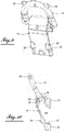
- FIG. 13A shows the lashing ring 9 in its lashing position, in which the base is engaged in the housing 25. In this position, the ring extends outward through a cutout 50 in the chassis 7 and is supported at 51 on the edge of this cut while being inclined at an angle of for example 30 degrees. Since the ring is in support, the operator who must hang the securing means at the top of the ring, no longer needs to hold it.
- the figure 13B shows the ring in another extended position in which it rests on the outer horizontal edge 32 of the cutout 50.
- the movement of the ring between these two positions is effected by pivoting of the ring and by rotation of the base in its housing 25. Only by raising the ring vertically, in the position shown in the figure 7 where the flat 19 is located practically perpendicular to the housing exit surface, that is to say the passage, and by exerting a slight rotation, the flat portion of the ring can be passed through the narrowing produced by the boss and through it in the space 26 below, as shown in the figure 8 . After the ring base has passed through the larger space below, the ring can be pivoted to its position shown in the illustration.
- the figure 14 shows the mounting of the support for the lashing arrangement on an IPN-shaped beam. As illustrated in the figures, the support is fixed either by screws or by welding on the profile blade.
- the support for the lashing ring may have any other suitable shape, provided that the housing for the base of the ring, of cylindrical shape over at least the major part of its periphery, and a part in the form of a flat, and the passage of width narrowed but slightly greater than the thickness of the base, perpendicular to the flat , so as to allow the passage of the base from its housing towards the displacement space situated below, only as a function of the angular position of the base relative to the passage.
- the groove for receiving the rounded part of the stirrup of the ring and the bearing surface of the base configured so as to ensure a retracted position of the ring without play can be produced in a way appropriate different.
Description
L'invention concerne un agencement d'arrimage d'objets sur une surface notamment d'un plancher de chargement d'un véhicule de transport de cargaisons, du type décrit dans le préambule de la revendication 1.The invention relates to an arrangement for securing objects on a surface in particular of a loading floor of a cargo transport vehicle, of the type described in the preamble of claim 1.
Il est connu de doter des véhicules de transport de cargaison de différents points d'arrimage qui sont généralement situés dans le plancher ou sur les longerons du véhicule et situés sur le bord de rive de celui-ci. Ils sont conçus pour permettre la mise en place de la charge sans perturbation et restent accessibles, en nombre suffisant, pour procéder à l'arrimage de cette charge en vue d'un transport, sans risque de perte et affleurant au plancher pour éviter tout risque d'accident pour les personnes se déplaçant sur ce plancher.It is known practice to provide cargo transport vehicles with different lashing points which are generally located in the floor or on the side members of the vehicle and located on the edge thereof. They are designed to allow the load to be put in place without disturbance and remain accessible, in sufficient number, to secure this load for transport, without risk of loss and flush with the floor to avoid any risk. accident for people moving on this floor.
Les agencements d'arrimage qui sont connus tels que celui décrit dans le document
L'invention a pour but de pallier ces inconvénients.The invention aims to overcome these drawbacks.
Pour atteindre ce but, l'agencement d'arrimage selon l'invention comporte les caractéristiques qui sont énoncées dans la partie caractérisante de la revendication 1.To achieve this object, the securing arrangement according to the invention includes the characteristics which are set out in the characterizing part of claim 1.
D'autres caractéristiques avantageuses de l'invention sont décrites dans les revendications dépendantes.Other advantageous features of the invention are described in the dependent claims.
L'invention sera mieux comprise, et d'autres buts, caractéristiques, détails et avantages de celle-ci apparaîtront plus clairement dans la description explicative qui va suivre faite en référence aux dessins annexés donnés uniquement à titre d'exemple illustrant un mode de réalisation de l'invention et dans lesquels :
- La
figure 1 est une vue en perspective de l'agencement d'arrimage selon l'invention montrant celui-ci dans une position d'arrimage d'un objet sur un plancher de chargement ; - la
figure 2 est une vue en perspective montrant l'agencement d'arrimage dans sa position escamotée de son anneau d'arrimage ; - la
figure 3 est une vue en perspective du support de l'anneau d'arrimage, de l'agencement d'arrimage selon l'invention ; - la
figure 4 est une vue en perspective d'un anneau d'arrimage selon l'invention ; - la
figure 5 est une vue en perspective à plus grande échelle de l'agencement d'arrimage de lafigure 1 ; - les
figures 6 à 8 sont des vues en coupe le long de la ligne VI-VI de lafigure 5 et montrent l'anneau d'arrimage dans trois positions différentes dans son support ; - la
figure 9 est une vue en perspective de l'agencement d'arrimage selon l'invention ; - la
figure 10 est une vue latérale de l'agencement d'arrimage selon lafigure 9 ; - les
figures 11 et 12 sont des vues latérales montrant l'anneau d'arrimage dans deux positions escamotées de repos ; - la
figure 13A à 13C illustrent la cinématique de l'anneau d'arrimage dans son support et la structure porteuse, en montrant l'anneau dans deux positions de travail et une position escamotée de repos ; - la
figure 14 est une vue en perspective de l'agencement d'arrimage selon l'invention montée sur un longeron en forme d'IPN.
- The
figure 1 is a perspective view of the stowage arrangement according to the invention showing it in a stowed position of an object on a loading floor; - the
figure 2 is a perspective view showing the lashing arrangement in its retracted position of its lashing ring; - the
figure 3 is a perspective view of the support of the lashing ring, of the lashing arrangement according to the invention; - the
figure 4 is a perspective view of a lashing ring according to the invention; - the
figure 5 is a perspective view on a larger scale of the stowage arrangement of thefigure 1 ; - the
figures 6 to 8 are sectional views along line VI-VI of thefigure 5 and show the lashing ring in three different positions in its holder; - the
figure 9 is a perspective view of the stowage arrangement according to the invention; - the
figure 10 is a side view of the stowage arrangement according to thefigure 9 ; - the
Figures 11 and 12 are side views showing the lashing ring in two retracted rest positions; - the
figure 13A to 13C illustrate the kinematics of the lashing ring in its support and the supporting structure, showing the ring in two working positions and a retracted rest position; - the
figure 14 is a perspective view of the lashing arrangement according to the invention mounted on a beam in the form of IPN.
Comme le montrent, de façon générale, les
L'agencement d'arrimage selon l'invention comprend un anneau d'arrimage 9 et un support d'anneau 10 qui est monté dans le châssis. La
On décrira ci-après la structure de l'agencement d'arrimage 1 plus en détails, en se référant aux
Comme le montrent notamment la
Selon une caractéristique particulière de l'invention, la partie de chape verticale 29 est pourvue d'un bossage 34 qui fait saillie en direction de la partie recourbée en regard 31. La surface supérieure du bossage est en forme d'un arc de cercle ayant le même rayon de courbure que le logement 25 en continuant la courbure de celui-ci. Ce bossage est situé, par rapport à la largeur de la chape, dans la partie centrale de la partie de chape 29 au niveau du méplat dans la base cylindrique de l'anneau. Le bossage rétrécit ainsi le passage 35 entre le logement cylindrique 25 et l'espace 26 en-dessous de ce logement, de façon que ce passage n'est que légèrement supérieur à l'épaisseur de la base de l'anneau au niveau du méplat, c'est-à-dire à l'épaisseur de la base perpendiculairement à ce dernier. Ainsi, la base peut sortir du logement 25 seulement lorsqu'il se trouve dans une position angulaire dans laquelle le méplat se situe juste au-dessus du passage, comme cela sera expliqué plus loin.According to a particular characteristic of the invention, the
Les figures montrent encore que la surface extérieure de la patte de fixation supérieure 21 est en forme d'une gorge qui est courbée dans un plan parallèle à la surface de fixation du châssis, d'une part et dont le fond est également courbé, de façon complémentaire au diamètre de la courbure de l'étrier et au diamètre de l'étrier, de façon que l'étrier puisse se loger dans cette gorge dans sa position rétractée. Dans cette position, la base de l'anneau est en appui sur une surface d'appui 37 de la patte de fixation inférieure 22. Il est encore à noter que la partie de chape inclinée 28 présente en bas, au-dessus de sa patte de fixation 22 un bossage extérieur 39 sur laquelle peut prendre appui la partie haute de l'étrier dans la position rétractée de la
Concernant la fixation du support sur la face des fixations de la structure porteuse, celle-ci peut être fait par des vis, à savoir, par trois vis, dont les trous de passages sont indiqués en 45. Cette fixation peut aussi être réalisée par soudage.Regarding the fixing of the support on the face of the fastenings of the supporting structure, this can be done by screws, namely, by three screws, the passage holes of which are indicated at 45. This fixing can also be carried out by welding .
En se référant aux
La
La
Bien entendu, de multiples modifications peuvent être apportées à l'agencement d'arrimage tel que décrit et représenté sur les figures. Ainsi, le support de l'anneau d'arrimage peut avoir tout autre forme appropriée, à condition de conserver le logement de la base de l'anneau, de forme cylindrique sur au moins la grande partie de sa périphérie, et une partie en forme d'un méplat, et le passage de largeur rétrécie mais légèrement supérieure à l'épaisseur de la base, perpendiculairement au méplat, de façon à permettre le passage de la base de son logement vers l'espace de déplacement situé en-dessous, seulement en fonction de la position angulaire de la base par rapport au passage. De plus, la gorge de réception de la partie arrondie de l'étrier de l'anneau et la surface d'appui de la base, configurée de façon à assurer une position escamotée de l'anneau sans jeu peuvent être réalisées d'une manière appropriée différente.Of course, multiple modifications can be made to the stowage arrangement as described and shown in the figures. Thus, the support for the lashing ring may have any other suitable shape, provided that the housing for the base of the ring, of cylindrical shape over at least the major part of its periphery, and a part in the form of a flat, and the passage of width narrowed but slightly greater than the thickness of the base, perpendicular to the flat , so as to allow the passage of the base from its housing towards the displacement space situated below, only as a function of the angular position of the base relative to the passage. In addition, the groove for receiving the rounded part of the stirrup of the ring and the bearing surface of the base, configured so as to ensure a retracted position of the ring without play can be produced in a way appropriate different.
Claims (6)
- An arrangement for securing objects on a surface, in particular a loading floor (5) of a cargo transport vehicle, of the type comprising a ring (9) for securing and detaching a securing means (14) such as a strap or chain, and a support (10) in the form of a yoke intended to be fastened on a support structure (7) and in which the ring is movable between at least a securing position and an idle position, the ring comprising a cylindrical rectilinear base engaged in a housing with a shape complementary to the support, allowing the ring to pivot in said securing position, by rotating the base in the housing, characterized in that the cylindrical base of the securing ring (9) comprises a central flat part (19) and in that the support of the securing ring (10) comprises, in its end adjacent to the loading floor surface (5), a housing (25) for the base (17) allowing the latter to rotate in this housing, and below the housing, a space (26) for movement of the base (17) and allowing the movement of the ring in a retracted storage position, and in that the housing (25) is separated from the movement space (26) by a narrow passage zone (35) of the base toward the space (26), the width of which is slightly greater than the thickness of the base at the flat part (19), perpendicular to the flat, in order to allow the passage of the base (17) from the housing (25) toward the movement space (26) only when the base is found in a position in which the flat is oriented perpendicular to the passage.
- The securing arrangement according to claim 1, characterized in that the support (10) of the securing ring includes, in the outer face of its upper end, a housing groove (36) of the fastening apex (16) of the ring, and at its lower end, a bearing surface (37) on which the base (17) bears without play when the ring is in its retracted position.
- The securing arrangement according to claims 1 to 2, characterized in that the securing ring extends, in its securing position, past the loading floor surface (5), through a cutout (50) in the support structure, by a predetermined angle relative to the floor surface (5) and in that the ring is kept in this position by a bearing means (51).
- The securing arrangement according to one of claims 1 to 3, characterized in that the support (10) of the securing ring (9) is able to be fastened on a fastening surface (24) by screws or by welding.
- The securing arrangement according to one of claims 1 to 4, characterized in that the support (10) of the securing ring (9) is made up of a yoke in the form of a strip whereof the ends each terminate in a fastening tab (21 or 22) at a surface (24) of the support structure, which is perpendicular to the floor surface (5), the upper end part adjacent to the floor surface (5) being curved toward said fastening surface while forming, at the apex, the semi-cylindrical housing (25) of the cylindrical base (17) of the ring (9), while the yoke strip forms, below the housing, the movement space (26) of the base (9) that is separated from the housing (25) by the narrow passage by the flat part (19).
- The securing arrangement according to claim 5, characterized in that the support (9) of the securing ring (10) in the form of a yoke comprises an inclined median part (28) relative to the fastening surface (24), which terminates at the bottom by the lower fastening tab (22) and which extends at the top by a vertical part (29) whereof the end portion (30, 31) is curved by an angle of 180 degrees and bears, at its end, the upper fastening tab (21) that extends perpendicular to this end and to the fastening surface (24) and has, on its outer surface, the groove for receiving the apex of the securing ring.
Priority Applications (1)
| Application Number | Priority Date | Filing Date | Title |
|---|---|---|---|
| PL17199391T PL3323676T3 (en) | 2016-11-16 | 2017-10-31 | Arrangement for securing objects on a surface, in particular a loading floor of a cargo transport vehicle |
Applications Claiming Priority (1)
| Application Number | Priority Date | Filing Date | Title |
|---|---|---|---|
| FR1661106A FR3058688B1 (en) | 2016-11-16 | 2016-11-16 | ARRIMAGE ARRANGEMENT OF OBJECTS ON A SURFACE, IN PARTICULAR A LOADING FLOOR OF A CARGO TRANSPORT VEHICLE |
Publications (2)
| Publication Number | Publication Date |
|---|---|
| EP3323676A1 EP3323676A1 (en) | 2018-05-23 |
| EP3323676B1 true EP3323676B1 (en) | 2020-02-26 |
Family
ID=57909669
Family Applications (1)
| Application Number | Title | Priority Date | Filing Date |
|---|---|---|---|
| EP17199391.8A Active EP3323676B1 (en) | 2016-11-16 | 2017-10-31 | Arrangement for securing objects on a surface, in particular a loading floor of a cargo transport vehicle |
Country Status (4)
| Country | Link |
|---|---|
| EP (1) | EP3323676B1 (en) |
| ES (1) | ES2793403T3 (en) |
| FR (1) | FR3058688B1 (en) |
| PL (1) | PL3323676T3 (en) |
Families Citing this family (1)
| Publication number | Priority date | Publication date | Assignee | Title |
|---|---|---|---|---|
| CN111609794B (en) * | 2020-04-24 | 2022-04-22 | 北京控制工程研究所 | Target satellite and rocket docking ring capturing point positioning method based on capturing of two mechanical arms |
Family Cites Families (3)
| Publication number | Priority date | Publication date | Assignee | Title |
|---|---|---|---|---|
| FR2782040B1 (en) * | 1998-08-07 | 2000-10-06 | Pommier & Cie | LOCKING RING ARRANGEMENT FOR RECESSING INTO THE EDGE OF A VEHICLE SUCH AS A CARRIER, A TRAILER OR SEMI-TRAILER |
| DE202006007916U1 (en) * | 2006-05-17 | 2006-08-24 | Koninklijke Nooteboom Trailers B.V. | System for lashing loads on e.g. lorries comprises shackles in slots along edge of lorry which are mounted on bolts between vertical walls, allowing them to swivel, bolts being able to slide between walls |
| DE202015100750U1 (en) * | 2015-02-17 | 2015-03-03 | Thiele Gmbh & Co. Kg | lashing point |
-
2016
- 2016-11-16 FR FR1661106A patent/FR3058688B1/en not_active Expired - Fee Related
-
2017
- 2017-10-31 ES ES17199391T patent/ES2793403T3/en active Active
- 2017-10-31 PL PL17199391T patent/PL3323676T3/en unknown
- 2017-10-31 EP EP17199391.8A patent/EP3323676B1/en active Active
Non-Patent Citations (1)
| Title |
|---|
| None * |
Also Published As
| Publication number | Publication date |
|---|---|
| PL3323676T3 (en) | 2020-11-02 |
| ES2793403T3 (en) | 2020-11-13 |
| EP3323676A1 (en) | 2018-05-23 |
| FR3058688A1 (en) | 2018-05-18 |
| FR3058688B1 (en) | 2018-12-07 |
Similar Documents
| Publication | Publication Date | Title |
|---|---|---|
| EP2586648B1 (en) | System comprising an automobile seat rail and a mounting intended for being attached thereto, and method for manufacturing such a system | |
| EP3323676B1 (en) | Arrangement for securing objects on a surface, in particular a loading floor of a cargo transport vehicle | |
| EP2890906B1 (en) | Ring for attaching a bolt to a support and assembly obtained | |
| CH644312A5 (en) | TIRE CHAIN. | |
| FR3030405A1 (en) | REAR SAFETY BELT REEL COMPRISING A TABLET HAVING A REINFORCED REINFORCEMENT. | |
| FR2782040A1 (en) | Retractable stowage ring, used on vehicles, has cut-out in upper face of edge of vehicle, with stowage ring retractable into space formed by cut-out and beneath ring support, which is fitted into cut-out. | |
| EP1870602B1 (en) | Piece for assembling two elements, associated assembly device and application to the field of automobiles | |
| WO2012114018A1 (en) | Device for attaching a spare wheel of a vehicle | |
| EP3658790B1 (en) | Nut cage system comprising a nut cage and a support on which the cage is intended to be mounted | |
| EP3168119A1 (en) | System for securing an accessory, in particular a piece of luggage, on a motorcycle | |
| EP2867098B1 (en) | Fastening device for joining the side end of a bumper skirt to a vehicle body panel | |
| FR2974326A1 (en) | CONNECTION SYSTEM FOR FASTENING A CARRYING DEVICE | |
| FR2698592A1 (en) | Floor mounting for removable seats - has floor-mounted hooks engaging with sockets in base of seat | |
| FR2725780A1 (en) | METHOD FOR FASTENING A NOZZLE ON A COOLING RADIATOR | |
| EP3678894B1 (en) | Anchoring device for a removable seat on a motor vehicle floor | |
| EP3392086B1 (en) | Arrangement of a securing ring on a supporting structure such as the bank edge or a floor, in particular for loading a transport vehicle | |
| FR2581933A1 (en) | Transporting trolley, especially for the customers of self-service stores | |
| EP2341014B1 (en) | Modular hook for covering element | |
| EP1907739B1 (en) | Assembly to be mounted under a fixed support such as a motor vehicle body shell floor, and method for using same | |
| EP4169770A1 (en) | Shelf of a goods transport compartment | |
| FR2871943A1 (en) | Case e.g. battery, positioning and fixing device for motor vehicle, has stop portion connecting lower and upper support portions at side opposite to wall and limiting movement of battery, where upper portion has lug contacting with wall | |
| FR2706409A1 (en) | Device for reversibly fastening a seat to the floor of a motor vehicle | |
| EP3119620B1 (en) | System for coupling a range of carriers with a swivel hook fixed to the rear structure of a motor vehicle | |
| FR3082592A1 (en) | CONFORMED PANEL EDGE FOR RECEIVING A NIPPERS. | |
| FR2930610A1 (en) | FIXING ELEMENT COMPRISING AN NUT FOR OPEN PROFILE RAIL |
Legal Events
| Date | Code | Title | Description |
|---|---|---|---|
| PUAI | Public reference made under article 153(3) epc to a published international application that has entered the european phase |
Free format text: ORIGINAL CODE: 0009012 |
|
| STAA | Information on the status of an ep patent application or granted ep patent |
Free format text: STATUS: THE APPLICATION HAS BEEN PUBLISHED |
|
| AK | Designated contracting states |
Kind code of ref document: A1 Designated state(s): AL AT BE BG CH CY CZ DE DK EE ES FI FR GB GR HR HU IE IS IT LI LT LU LV MC MK MT NL NO PL PT RO RS SE SI SK SM TR |
|
| AX | Request for extension of the european patent |
Extension state: BA ME |
|
| STAA | Information on the status of an ep patent application or granted ep patent |
Free format text: STATUS: REQUEST FOR EXAMINATION WAS MADE |
|
| 17P | Request for examination filed |
Effective date: 20180924 |
|
| RBV | Designated contracting states (corrected) |
Designated state(s): AL AT BE BG CH CY CZ DE DK EE ES FI FR GB GR HR HU IE IS IT LI LT LU LV MC MK MT NL NO PL PT RO RS SE SI SK SM TR |
|
| GRAP | Despatch of communication of intention to grant a patent |
Free format text: ORIGINAL CODE: EPIDOSNIGR1 |
|
| STAA | Information on the status of an ep patent application or granted ep patent |
Free format text: STATUS: GRANT OF PATENT IS INTENDED |
|
| INTG | Intention to grant announced |
Effective date: 20190913 |
|
| GRAS | Grant fee paid |
Free format text: ORIGINAL CODE: EPIDOSNIGR3 |
|
| GRAA | (expected) grant |
Free format text: ORIGINAL CODE: 0009210 |
|
| STAA | Information on the status of an ep patent application or granted ep patent |
Free format text: STATUS: THE PATENT HAS BEEN GRANTED |
|
| AK | Designated contracting states |
Kind code of ref document: B1 Designated state(s): AL AT BE BG CH CY CZ DE DK EE ES FI FR GB GR HR HU IE IS IT LI LT LU LV MC MK MT NL NO PL PT RO RS SE SI SK SM TR |
|
| REG | Reference to a national code |
Ref country code: GB Ref legal event code: FG4D Free format text: NOT ENGLISH |
|
| REG | Reference to a national code |
Ref country code: CH Ref legal event code: EP |
|
| REG | Reference to a national code |
Ref country code: AT Ref legal event code: REF Ref document number: 1237217 Country of ref document: AT Kind code of ref document: T Effective date: 20200315 |
|
| REG | Reference to a national code |
Ref country code: IE Ref legal event code: FG4D Free format text: LANGUAGE OF EP DOCUMENT: FRENCH |
|
| REG | Reference to a national code |
Ref country code: DE Ref legal event code: R096 Ref document number: 602017012208 Country of ref document: DE |
|
| REG | Reference to a national code |
Ref country code: NL Ref legal event code: FP |
|
| PG25 | Lapsed in a contracting state [announced via postgrant information from national office to epo] |
Ref country code: NO Free format text: LAPSE BECAUSE OF FAILURE TO SUBMIT A TRANSLATION OF THE DESCRIPTION OR TO PAY THE FEE WITHIN THE PRESCRIBED TIME-LIMIT Effective date: 20200526 Ref country code: FI Free format text: LAPSE BECAUSE OF FAILURE TO SUBMIT A TRANSLATION OF THE DESCRIPTION OR TO PAY THE FEE WITHIN THE PRESCRIBED TIME-LIMIT Effective date: 20200226 Ref country code: RS Free format text: LAPSE BECAUSE OF FAILURE TO SUBMIT A TRANSLATION OF THE DESCRIPTION OR TO PAY THE FEE WITHIN THE PRESCRIBED TIME-LIMIT Effective date: 20200226 |
|
| REG | Reference to a national code |
Ref country code: LT Ref legal event code: MG4D |
|
| PG25 | Lapsed in a contracting state [announced via postgrant information from national office to epo] |
Ref country code: BG Free format text: LAPSE BECAUSE OF FAILURE TO SUBMIT A TRANSLATION OF THE DESCRIPTION OR TO PAY THE FEE WITHIN THE PRESCRIBED TIME-LIMIT Effective date: 20200526 Ref country code: IS Free format text: LAPSE BECAUSE OF FAILURE TO SUBMIT A TRANSLATION OF THE DESCRIPTION OR TO PAY THE FEE WITHIN THE PRESCRIBED TIME-LIMIT Effective date: 20200626 Ref country code: SE Free format text: LAPSE BECAUSE OF FAILURE TO SUBMIT A TRANSLATION OF THE DESCRIPTION OR TO PAY THE FEE WITHIN THE PRESCRIBED TIME-LIMIT Effective date: 20200226 Ref country code: LV Free format text: LAPSE BECAUSE OF FAILURE TO SUBMIT A TRANSLATION OF THE DESCRIPTION OR TO PAY THE FEE WITHIN THE PRESCRIBED TIME-LIMIT Effective date: 20200226 Ref country code: GR Free format text: LAPSE BECAUSE OF FAILURE TO SUBMIT A TRANSLATION OF THE DESCRIPTION OR TO PAY THE FEE WITHIN THE PRESCRIBED TIME-LIMIT Effective date: 20200527 Ref country code: HR Free format text: LAPSE BECAUSE OF FAILURE TO SUBMIT A TRANSLATION OF THE DESCRIPTION OR TO PAY THE FEE WITHIN THE PRESCRIBED TIME-LIMIT Effective date: 20200226 |
|
| PG25 | Lapsed in a contracting state [announced via postgrant information from national office to epo] |
Ref country code: SK Free format text: LAPSE BECAUSE OF FAILURE TO SUBMIT A TRANSLATION OF THE DESCRIPTION OR TO PAY THE FEE WITHIN THE PRESCRIBED TIME-LIMIT Effective date: 20200226 Ref country code: LT Free format text: LAPSE BECAUSE OF FAILURE TO SUBMIT A TRANSLATION OF THE DESCRIPTION OR TO PAY THE FEE WITHIN THE PRESCRIBED TIME-LIMIT Effective date: 20200226 Ref country code: DK Free format text: LAPSE BECAUSE OF FAILURE TO SUBMIT A TRANSLATION OF THE DESCRIPTION OR TO PAY THE FEE WITHIN THE PRESCRIBED TIME-LIMIT Effective date: 20200226 Ref country code: EE Free format text: LAPSE BECAUSE OF FAILURE TO SUBMIT A TRANSLATION OF THE DESCRIPTION OR TO PAY THE FEE WITHIN THE PRESCRIBED TIME-LIMIT Effective date: 20200226 Ref country code: SM Free format text: LAPSE BECAUSE OF FAILURE TO SUBMIT A TRANSLATION OF THE DESCRIPTION OR TO PAY THE FEE WITHIN THE PRESCRIBED TIME-LIMIT Effective date: 20200226 Ref country code: PT Free format text: LAPSE BECAUSE OF FAILURE TO SUBMIT A TRANSLATION OF THE DESCRIPTION OR TO PAY THE FEE WITHIN THE PRESCRIBED TIME-LIMIT Effective date: 20200719 Ref country code: RO Free format text: LAPSE BECAUSE OF FAILURE TO SUBMIT A TRANSLATION OF THE DESCRIPTION OR TO PAY THE FEE WITHIN THE PRESCRIBED TIME-LIMIT Effective date: 20200226 Ref country code: CZ Free format text: LAPSE BECAUSE OF FAILURE TO SUBMIT A TRANSLATION OF THE DESCRIPTION OR TO PAY THE FEE WITHIN THE PRESCRIBED TIME-LIMIT Effective date: 20200226 |
|
| REG | Reference to a national code |
Ref country code: ES Ref legal event code: FG2A Ref document number: 2793403 Country of ref document: ES Kind code of ref document: T3 Effective date: 20201113 |
|
| REG | Reference to a national code |
Ref country code: AT Ref legal event code: MK05 Ref document number: 1237217 Country of ref document: AT Kind code of ref document: T Effective date: 20200226 |
|
| REG | Reference to a national code |
Ref country code: DE Ref legal event code: R097 Ref document number: 602017012208 Country of ref document: DE |
|
| PLBE | No opposition filed within time limit |
Free format text: ORIGINAL CODE: 0009261 |
|
| STAA | Information on the status of an ep patent application or granted ep patent |
Free format text: STATUS: NO OPPOSITION FILED WITHIN TIME LIMIT |
|
| PG25 | Lapsed in a contracting state [announced via postgrant information from national office to epo] |
Ref country code: AT Free format text: LAPSE BECAUSE OF FAILURE TO SUBMIT A TRANSLATION OF THE DESCRIPTION OR TO PAY THE FEE WITHIN THE PRESCRIBED TIME-LIMIT Effective date: 20200226 |
|
| 26N | No opposition filed |
Effective date: 20201127 |
|
| PG25 | Lapsed in a contracting state [announced via postgrant information from national office to epo] |
Ref country code: SI Free format text: LAPSE BECAUSE OF FAILURE TO SUBMIT A TRANSLATION OF THE DESCRIPTION OR TO PAY THE FEE WITHIN THE PRESCRIBED TIME-LIMIT Effective date: 20200226 |
|
| PGFP | Annual fee paid to national office [announced via postgrant information from national office to epo] |
Ref country code: BE Payment date: 20201029 Year of fee payment: 4 |
|
| REG | Reference to a national code |
Ref country code: CH Ref legal event code: PL |
|
| PG25 | Lapsed in a contracting state [announced via postgrant information from national office to epo] |
Ref country code: LU Free format text: LAPSE BECAUSE OF NON-PAYMENT OF DUE FEES Effective date: 20201031 Ref country code: MC Free format text: LAPSE BECAUSE OF FAILURE TO SUBMIT A TRANSLATION OF THE DESCRIPTION OR TO PAY THE FEE WITHIN THE PRESCRIBED TIME-LIMIT Effective date: 20200226 |
|
| PG25 | Lapsed in a contracting state [announced via postgrant information from national office to epo] |
Ref country code: LI Free format text: LAPSE BECAUSE OF NON-PAYMENT OF DUE FEES Effective date: 20201031 Ref country code: CH Free format text: LAPSE BECAUSE OF NON-PAYMENT OF DUE FEES Effective date: 20201031 |
|
| PG25 | Lapsed in a contracting state [announced via postgrant information from national office to epo] |
Ref country code: IE Free format text: LAPSE BECAUSE OF NON-PAYMENT OF DUE FEES Effective date: 20201031 |
|
| PG25 | Lapsed in a contracting state [announced via postgrant information from national office to epo] |
Ref country code: TR Free format text: LAPSE BECAUSE OF FAILURE TO SUBMIT A TRANSLATION OF THE DESCRIPTION OR TO PAY THE FEE WITHIN THE PRESCRIBED TIME-LIMIT Effective date: 20200226 Ref country code: MT Free format text: LAPSE BECAUSE OF FAILURE TO SUBMIT A TRANSLATION OF THE DESCRIPTION OR TO PAY THE FEE WITHIN THE PRESCRIBED TIME-LIMIT Effective date: 20200226 Ref country code: CY Free format text: LAPSE BECAUSE OF FAILURE TO SUBMIT A TRANSLATION OF THE DESCRIPTION OR TO PAY THE FEE WITHIN THE PRESCRIBED TIME-LIMIT Effective date: 20200226 |
|
| REG | Reference to a national code |
Ref country code: BE Ref legal event code: MM Effective date: 20211031 |
|
| PG25 | Lapsed in a contracting state [announced via postgrant information from national office to epo] |
Ref country code: MK Free format text: LAPSE BECAUSE OF FAILURE TO SUBMIT A TRANSLATION OF THE DESCRIPTION OR TO PAY THE FEE WITHIN THE PRESCRIBED TIME-LIMIT Effective date: 20200226 Ref country code: AL Free format text: LAPSE BECAUSE OF FAILURE TO SUBMIT A TRANSLATION OF THE DESCRIPTION OR TO PAY THE FEE WITHIN THE PRESCRIBED TIME-LIMIT Effective date: 20200226 |
|
| PG25 | Lapsed in a contracting state [announced via postgrant information from national office to epo] |
Ref country code: BE Free format text: LAPSE BECAUSE OF NON-PAYMENT OF DUE FEES Effective date: 20211031 |
|
| P01 | Opt-out of the competence of the unified patent court (upc) registered |
Effective date: 20230518 |
|
| PGFP | Annual fee paid to national office [announced via postgrant information from national office to epo] |
Ref country code: PL Payment date: 20230929 Year of fee payment: 7 Ref country code: NL Payment date: 20231023 Year of fee payment: 7 |
|
| PGFP | Annual fee paid to national office [announced via postgrant information from national office to epo] |
Ref country code: GB Payment date: 20231023 Year of fee payment: 7 |
|
| PGFP | Annual fee paid to national office [announced via postgrant information from national office to epo] |
Ref country code: ES Payment date: 20231102 Year of fee payment: 7 |
|
| PGFP | Annual fee paid to national office [announced via postgrant information from national office to epo] |
Ref country code: IT Payment date: 20231030 Year of fee payment: 7 Ref country code: FR Payment date: 20231010 Year of fee payment: 7 Ref country code: DE Payment date: 20231030 Year of fee payment: 7 |