EP3323645A1 - Concertina device for connecting and closing articulated buses - Google Patents
Concertina device for connecting and closing articulated buses Download PDFInfo
- Publication number
- EP3323645A1 EP3323645A1 EP17201768.3A EP17201768A EP3323645A1 EP 3323645 A1 EP3323645 A1 EP 3323645A1 EP 17201768 A EP17201768 A EP 17201768A EP 3323645 A1 EP3323645 A1 EP 3323645A1
- Authority
- EP
- European Patent Office
- Prior art keywords
- concertina
- tunnel
- side walls
- closing
- stiffening
- Prior art date
- Legal status (The legal status is an assumption and is not a legal conclusion. Google has not performed a legal analysis and makes no representation as to the accuracy of the status listed.)
- Granted
Links
Images


Classifications
-
- B—PERFORMING OPERATIONS; TRANSPORTING
- B60—VEHICLES IN GENERAL
- B60D—VEHICLE CONNECTIONS
- B60D5/00—Gangways for coupled vehicles, e.g. of concertina type
- B60D5/003—Bellows for interconnecting vehicle parts
-
- B—PERFORMING OPERATIONS; TRANSPORTING
- B61—RAILWAYS
- B61D—BODY DETAILS OR KINDS OF RAILWAY VEHICLES
- B61D17/00—Construction details of vehicle bodies
- B61D17/04—Construction details of vehicle bodies with bodies of metal; with composite, e.g. metal and wood body structures
- B61D17/20—Communication passages between coaches; Adaptation of coach ends therefor
- B61D17/22—Communication passages between coaches; Adaptation of coach ends therefor flexible, e.g. bellows
-
- B—PERFORMING OPERATIONS; TRANSPORTING
- B62—LAND VEHICLES FOR TRAVELLING OTHERWISE THAN ON RAILS
- B62D—MOTOR VEHICLES; TRAILERS
- B62D47/00—Motor vehicles or trailers predominantly for carrying passengers
- B62D47/02—Motor vehicles or trailers predominantly for carrying passengers for large numbers of passengers, e.g. omnibus
- B62D47/025—Motor vehicles or trailers predominantly for carrying passengers for large numbers of passengers, e.g. omnibus articulated buses with interconnecting passageway, e.g. bellows
Definitions
- the present invention relates to a concertina for connecting and closing articulated road vehicles.
- this invention can be advantageously applied where adjacent carriages of buses are to be joined together.
- the connecting zone must inevitably guarantee safe conditions even when the bus goes round a bend, that is to say, even when the two carriages are not aligned with each other allowing a tunnel-like free passage.
- the connecting zone is closed inside a concertina, which is shaped to define a tunnel for passage between the two carriages, to which it is connected.
- the ends of the concertina are connected to the free ends of the two carriages, in such a way that the concertina deforms when the bus adopts configurations wherein the two carriages are not are aligned with each other.
- a concertina of this type normally has a plurality of bands, which are made of flexible material, usually plasticised fabric, which are equipped with stiffening frames and are sewn together longitudinally.
- the concertina also extends partly under the rotary platform and is closed at the bottom.
- the aim of this invention is to satisfy the above-mentioned need of providing aconnection and closing concertina for articulated vehicles (buses) which can be replaced, in the case of damage, in a particularly quick and simple way.
- the numeral 1 denotes in its entirety a concertina device for connecting and closing the free space between the articulated unit of an articulated bus.
- Figure 1 shows the concertina 1 mounted on a bus 2 to join together the areas of two adjacent carriages 3 (or units 3) at the articulated joint (not illustrated) for connecting between the latter.
- the articulated joint allows the relative movement of the two articulated units 3.
- the concertina 1 is shaped to define a tunnel 4 for the passage and connection between the two carriages 3, to which it is connected.
- the ends 5 of the concertina are connected to the free ends 6 of the two carriages 3, in such a way that the concertina 1 deforms when the bus 2 adopts configurations wherein the two carriages 3 are not are aligned with each other, as occurs during the normal drive.
- the concertina 1 comprises a plurality of bands 7 made of flexible material and equipped with stiffening frames 8.
- the bands 7 are made of plasticised fabric and the stiffening frames 8 are made, generally, of aluminium (more generally of metal material).
- the bands 7 are joined together, one relative to another adjacent to it, to form the above-mentioned tunnel 4 for connection between two carriages 3.
- the bands 7 are sewn to each other.
- stiffening frames 8 The purpose of the stiffening frames 8 is to structurally stiffen the tunnel 4.
- the tunnel 4 is connected to the carriages 3 through respective end frames 9.
- the tunnel 4 comprises an upper wall 10 and two side walls 11.
- the concertina device 1 has a tubular shape and also extends under the rotary platform, and, according to the invention, is provided underneath with a replaceable bottom 12, that is, an interchangeable portion 12.
- the bottom 12 for closing the tunnel 4 is designed to act as a screen for the rotatable platform, screening it from the outside environment.
- the closing bottom 12 is formed by a plurality of bands 13 made of flexible material, joined together one alongside the other and equipped with a plurality of stiffening frames 14.
- the stiffening frames 14 are connected to the bands 13, preferably connected at the outer crests of them.
- the bands 13 are made of plasticised fabric and the stiffening frames 14 are made of metallic material (preferably aluminium).
- the bands 13 are preferably sewn together and the stiffening frames 14 are designed to structurally stiffen the closing bottom 12.
- the bands 13 and the stiffening frame 14 are aligned with the corresponding bands 7 and with the corresponding stiffening frames 8 of the tunnel 4 along respective closing lines L1 and L2 in the shape of a ring.
- the closing bottom 12 also follows substantially the same type of deformation.
- the closing bottom 12 comprises a lower wall 15, which is opposite the upper wall 10 of the tunnel 4, and two side walls 16, which are laterally alongside and fixed to, as described in detail below) the side walls 11 of the tunnel 4 inside the tunnel 4 itself.
- concertina 1 comprises basically two parts: an upper part, 100, with an inverted “U” shape, and a lower part or bottom 12 with a "U” shape.
- the bottom 12 is removably connectable to the upper part, 100.
- the two concertina side walls 16 are positioned side by side, generally in contact, inside the side walls 11 of the upper portion 100.
- the concertina 1 has a double layer, or more specifically, an inner layer, defined by the bands 13 of the side walls 16, and an outer layer, defined by the bands 7 of the side walls 11.
- the concertina device may comprise further fastening and connection elements (not illustrated) between the inner layer, defined by the bands 13 of the side walls 16, and the outer layer, defined by the bands 7 of the side walls 11.
- the elements may comprise one or more profiles and elements, which fix the bands 13 to the bands 7 in the lateral side-by-side zone defined above (which is located inside the tunnel 4).
- the upper part of the concertina 1, that is to say, the tunnel 4 is fitted on the lower part of the concertina 1, that is to say, on the closing bottom 12. This guarantees an effective run off of rainwater and prevents the rainwater, or splashes coming from the road surface, reaching the inside of the tunnel 4.
- Both the stiffening frames 8 and the stiffening frames 14 extend in a "U" shape.
- Each frame 8, 14 has, in the embodiment illustrated, a central stretch 8a, 14a which is straight and horizontal and two end stretches 8b, 14b which are straight and vertical, which are joined to the central stretch 8a, 14a by rounded corner portions 8c, 14c.
- the frames 8, 14 might have different profiles (not necessarily with straight stretches): more generally speaking, the frames 8, 14 can have curvilinear sections, alternated with the straight stretches, or only curvilinear sections.
- Figure 4 shows the upper portion 100 and the lower portion or bottom 12 uncoupled from each other.
- the tunnel 4 is connected to the carriages 3 through respective end frames 9.
- the bottom 12 is connected to the carriages by a removable fabric, not illustrated.
- the solution described above allows an assembling and disassembling of the bottom 12 for closing the tunnel 4 which is particularly fast.
- stiffening frames 8 and the stiffening the frames 14 are joined together by fastening means 18.
- the fastening means 18 are preferably screw fastening means to allow and easy assembly and easy disassembly of the bottom 12 for closing the tunnel 4.
- the fixing means 18 comprise automatic clips.
- the lower band of the tunnel 4 has a plurality of slots or openings 19 through which each stiffening frame 8 is connected and fixed to the corresponding stiffening frame 14.
- the bands 7 have a plurality of slots or openings 19 through which each stiffening frame 8 is connected and fixed to the corresponding stiffening frame 14.
- stiffening frames 14 of the bottom 12 are inserted passing freely through the openings 19, for coupling with the stiffening frames 8 of the tunnel 4, that is to say, of the upper portion 100.
- the fixing means between the frames 8, 14 could be of any type: for example, rivets, snap-in connecting elements, etc.
- the closing bottom 12 is coupled in a simple, effective and durable manner to the overlying part of the concertina 1, that is to say, to the tunnel 4, on the other hand, its removal is easy and fast, and its replacement makes it possible to easily overcome the problems of wear which often affect the lower corner portions of the concertinas.
- the invention also relates to a method for replacing an existing concertina device for connecting and closing the space between two units of an articulated bus, with the concertina device comprising a plurality of first stiffening frames and a concertina element extending annularly in the closed space comprising a lower wall, a pair of side walls facing each other and connected on both sides to the upper wall and a lower wall connected on both sides to the side walls, the method comprising the following steps:
- an articulated bus comprising:
Landscapes
- Engineering & Computer Science (AREA)
- Mechanical Engineering (AREA)
- Transportation (AREA)
- Wood Science & Technology (AREA)
- Chemical & Material Sciences (AREA)
- Combustion & Propulsion (AREA)
- Life Sciences & Earth Sciences (AREA)
- Lining And Supports For Tunnels (AREA)
- Diaphragms And Bellows (AREA)
- Body Structure For Vehicles (AREA)
- Tents Or Canopies (AREA)
- Cable Accessories (AREA)
- Supports For Pipes And Cables (AREA)
- Power-Operated Mechanisms For Wings (AREA)
- Gas-Insulated Switchgears (AREA)
Abstract
Description
- The present invention relates to a concertina for connecting and closing articulated road vehicles.
- More specifically, this invention can be advantageously applied where adjacent carriages of buses are to be joined together.
- Specific reference will be made below to the concertinas used at the joints of articulated buses.
- As is known, in an articulated bus, between the two carriages of which it is composed, there is a rotatable platform (known as "rack'), the purpose of which is also that of allowing both the passage and the standing of passengers in the connecting zone between the carriages.
- The connecting zone must inevitably guarantee safe conditions even when the bus goes round a bend, that is to say, even when the two carriages are not aligned with each other allowing a tunnel-like free passage.
- For that purpose, the connecting zone is closed inside a concertina, which is shaped to define a tunnel for passage between the two carriages, to which it is connected.
- More specifically, the ends of the concertina are connected to the free ends of the two carriages, in such a way that the concertina deforms when the bus adopts configurations wherein the two carriages are not are aligned with each other.
- A concertina of this type normally has a plurality of bands, which are made of flexible material, usually plasticised fabric, which are equipped with stiffening frames and are sewn together longitudinally.
- Generally speaking, the concertina also extends partly under the rotary platform and is closed at the bottom.
- It has been found, in particular in regions where the road surface is particularly uneven, that there is a rapid wear of the concertina, that is to say, a damage of the lower portion of the concertina (after, for example, impacts with the road surface).
- As a result of damage to the lower portion, the entire concertina or a central portion of the bottom is generally replaced at present.
- This obviously requires a stationary time of the vehicle which is particularly long and with considerable costs.
- The need is strongly felt for providing a solution which allows for the repair of the damaged concertina with low costs and with extremely reduced downtimes for the vehicle.
- The aim of this invention is to satisfy the above-mentioned need of providing aconnection and closing concertina for articulated vehicles (buses) which can be replaced, in the case of damage, in a particularly quick and simple way.
- This aim is fully achieved by the connection and closing concertina for articulated vehicles (buses) according to this invention, and as characterised in the appended claims.
- This aim is fully achieved by the replacement method according to this invention as characterised in the appended claims.
- The technical features of the invention will become more apparent from the following detailed description of a preferred, non-limiting embodiment, with reference to the accompanying drawings, in which:
-
Figure 1 shows an articulated vehicle, in particular a bus, equipped with a connection and containment concertina made in accordance with this invention; -
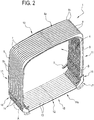
Figure 2 shows the concertina ofFigure 1 assembled in its operating configuration; -
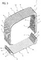
Figure 3 shows the concertina ofFigure 1 disassembled into two parts; -
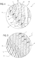
Figures 4 and 5 are two enlarged views of two respective details ofFigure 2 (Figure 4 shows the concertina in a partly assembled configuration); and -
Figure 6 shows a variant of the detail ofFigure 4 . - With reference to the accompanying drawings, the
numeral 1 denotes in its entirety a concertina device for connecting and closing the free space between the articulated unit of an articulated bus. - More specifically,
Figure 1 shows theconcertina 1 mounted on abus 2 to join together the areas of two adjacent carriages 3 (or units 3) at the articulated joint (not illustrated) for connecting between the latter. - The articulated joint, not illustrated, allows the relative movement of the two articulated
units 3. - There is a rotatable platform (not illustrated) at the articulated joint.
- The passage of the passengers is generally allowed at the articulated jointing the connecting zone between the
carriages 3. - The
concertina 1 is shaped to define atunnel 4 for the passage and connection between the twocarriages 3, to which it is connected. - More specifically, the
ends 5 of the concertina are connected to thefree ends 6 of the twocarriages 3, in such a way that theconcertina 1 deforms when thebus 2 adopts configurations wherein the twocarriages 3 are not are aligned with each other, as occurs during the normal drive. - As better illustrated in
Figures 2 and3 , theconcertina 1 comprises a plurality ofbands 7 made of flexible material and equipped withstiffening frames 8. - Preferably, the
bands 7 are made of plasticised fabric and thestiffening frames 8 are made, generally, of aluminium (more generally of metal material). - The
bands 7 are joined together, one relative to another adjacent to it, to form the above-mentionedtunnel 4 for connection between twocarriages 3. Preferably, but not necessarily, thebands 7 are sewn to each other. - The purpose of the
stiffening frames 8 is to structurally stiffen thetunnel 4. - The
tunnel 4 is connected to thecarriages 3 throughrespective end frames 9. - The
tunnel 4 comprises anupper wall 10 and twoside walls 11. - Under the rotatable platform (not illustrated) there can be pipes (not illustrated) and cables (not illustrated) which are necessary for the correct operation of the
carriages 3. - According to the invention, the
concertina device 1 has a tubular shape and also extends under the rotary platform, and, according to the invention, is provided underneath with areplaceable bottom 12, that is, aninterchangeable portion 12. - The
bottom 12 for closing thetunnel 4 is designed to act as a screen for the rotatable platform, screening it from the outside environment. - It may also attenuate the noise which strikes the platform from the road surface, in this way increasing the acoustic comfort for the passengers.
- The
closing bottom 12 is formed by a plurality ofbands 13 made of flexible material, joined together one alongside the other and equipped with a plurality ofstiffening frames 14. - The
stiffening frames 14 are connected to thebands 13, preferably connected at the outer crests of them. - Similarly to what is provided for the portion of the
concertina 1 which defines thetunnel 4, preferably, thebands 13 are made of plasticised fabric and thestiffening frames 14 are made of metallic material (preferably aluminium). - In this case, too, the
bands 13 are preferably sewn together and thestiffening frames 14 are designed to structurally stiffen theclosing bottom 12. - More specifically, as shown in
Figure 4 , thebands 13 and thestiffening frame 14 are aligned with thecorresponding bands 7 and with the correspondingstiffening frames 8 of thetunnel 4 along respective closing lines L1 and L2 in the shape of a ring. - In this way, when the
bus 2 meets a bend and thetunnel 4 compresses from the side facing towards the inside of the bend and extends from the side facing towards the outside of the bend, theclosing bottom 12 also follows substantially the same type of deformation. - The
closing bottom 12 comprises alower wall 15, which is opposite theupper wall 10 of thetunnel 4, and twoside walls 16, which are laterally alongside and fixed to, as described in detail below) theside walls 11 of thetunnel 4 inside thetunnel 4 itself. - It should be noted that the
concertina 1 comprises basically two parts: an upper part, 100, with an inverted "U" shape, and a lower part orbottom 12 with a "U" shape. - The
bottom 12 is removably connectable to the upper part, 100. - Preferably, the two
concertina side walls 16 are positioned side by side, generally in contact, inside theside walls 11 of theupper portion 100. - This positioning alongside each other is better shown in
Figure 5 , where it can be seen that theconcertina 1 has a double layer, or more specifically, an inner layer, defined by thebands 13 of theside walls 16, and an outer layer, defined by thebands 7 of theside walls 11. - It should be noted that, according to an embodiment not illustrated, the concertina device may comprise further fastening and connection elements (not illustrated) between the inner layer, defined by the
bands 13 of theside walls 16, and the outer layer, defined by thebands 7 of theside walls 11. - The elements may comprise one or more profiles and elements, which fix the
bands 13 to thebands 7 in the lateral side-by-side zone defined above (which is located inside the tunnel 4). - More specifically, the upper part of the
concertina 1, that is to say, thetunnel 4, is fitted on the lower part of theconcertina 1, that is to say, on theclosing bottom 12. This guarantees an effective run off of rainwater and prevents the rainwater, or splashes coming from the road surface, reaching the inside of thetunnel 4. - On the other hand, the coupling between the
upper portion 100 and thelower portion 12, that is to say, between thetunnel 4 and thebottom 12, occurs by coupling thestiffening frames - Both the
stiffening frames 8 and thestiffening frames 14 extend in a "U" shape. Eachframe central stretch central stretch rounded corner portions - It should be noted that, more generally speaking, the
frames frames -
Figure 4 shows theupper portion 100 and the lower portion orbottom 12 uncoupled from each other. - The
tunnel 4 is connected to thecarriages 3 throughrespective end frames 9. - The
bottom 12 is connected to the carriages by a removable fabric, not illustrated. - The solution described above allows an assembling and disassembling of the
bottom 12 for closing thetunnel 4 which is particularly fast. - Advantageously, in effect, in the event of damage to the
lower portion 12, it is possible to replace only thelower portion 12 in a particularly fast, simple and easy manner. - It is not necessary to remove the upper part of the
concertina device 1. - According to another aspect, clearly shown in the embodiment of
Figure 6 , the stiffening frames 8 and the stiffening theframes 14 are joined together by fasteningmeans 18. - The fastening means 18 are preferably screw fastening means to allow and easy assembly and easy disassembly of the bottom 12 for closing the
tunnel 4. - According to another embodiment, the fixing means 18 comprise automatic clips.
- In this case, at each
stiffening frame 8, the lower band of thetunnel 4 has a plurality of slots oropenings 19 through which eachstiffening frame 8 is connected and fixed to thecorresponding stiffening frame 14. - More specifically, the
bands 7 have a plurality of slots oropenings 19 through which eachstiffening frame 8 is connected and fixed to thecorresponding stiffening frame 14. - It should be noted that the stiffening frames 14 of the bottom 12 are inserted passing freely through the
openings 19, for coupling with the stiffening frames 8 of thetunnel 4, that is to say, of theupper portion 100. - The fixing means between the
frames - This solution guarantees a greater structural solidity of the
entire concertina 1. - The invention achieves the present aim. In effect, on the one hand, the closing
bottom 12 is coupled in a simple, effective and durable manner to the overlying part of theconcertina 1, that is to say, to thetunnel 4, on the other hand, its removal is easy and fast, and its replacement makes it possible to easily overcome the problems of wear which often affect the lower corner portions of the concertinas. - The invention also relates to a method for replacing an existing concertina device for connecting and closing the space between two units of an articulated bus, with the concertina device comprising a plurality of first stiffening frames and a concertina element extending annularly in the closed space comprising a lower wall, a pair of side walls facing each other and connected on both sides to the upper wall and a lower wall connected on both sides to the side walls, the method comprising the following steps:
- cutting a lower portion of the side walls of the concertina element, annulling the existing concertina device in such a way as to define an upper portion and a lower portion and removing the lower portion;
- preparing a plurality of
second bands 13 made of flexible material, joined together one alongside the other, equipped with a plurality of second stiffening frames 14 and forming aclosing bottom 12; - coupling the closing
bottom 12 to the upper portion of the existing concertina device, by a connection between the second stiffening frames 14 and the first stiffening frames. - Advantageously, according to the method, it is possible to also carry out the "retrofitting" on existing buses in a particularly simple, fast and inexpensive manner, by the maintenance operators for the buses.
- Also defined is an articulated bus, comprising:
- at least two articulated units;
- a connecting joint and junction interposed between the units to allow the relative movement;
- a concertina device as described above, designed to close the space between the two articulated units at the connecting joint.
Claims (11)
- A concertina device for connecting and closing the space between two articulated units of an articulated bus, comprising:a plurality of first bands (7), made with a concertina profile, made of flexible material, joined together one alongside the other, equipped with a plurality of first stiffening frames (8) and forming a tunnel (4) having an upper wall (10) and two side walls (11) for connecting together two carriages (3) of a vehicle (2);a plurality of second bands (13) made of flexible material, joined together one alongside the other, equipped with a plurality of second stiffening frames (14) and forming a bottom (12) for closing the tunnel (4);characterized in that:the closing bottom (12) comprises a lower wall (15), which is opposite the upper wall (10) of the tunnel (4) and two side walls (16), which are laterally alongside the side walls (11) of the tunnel (4).
- The concertina device according to claim 1, characterised in that the two side walls (16) are laterally alongside the side walls (11) of the tunnel (4) inside the tunnel (4) itself.
- The concertina device according to claim 1, characterised in that, in the zone in which the side walls (16) of the closing bottom (12) are laterally alongside the side walls (11) of the tunnel (4), the concertina (1) has a double layer formed by the first and second bands (7, 13).
- The concertina device according to any one of claims 1 to 3, characterised in that the tunnel (4) is fitted on the closing bottom (12).
- The concertina device according to any one of claims 1 to 4, characterised in that the first and second stiffening frames (8, 14) are U-shaped, each having a central stretch (8a, 14a) which is rectilinear and horizontal and two end stretches (8b, 14b) which are rectilinear and vertical, which are joined to the central stretch (8a, 14a) by rounded corner portions (8c, 14c).
- The concertina device according to any one of claims 1 to 5, characterised in that the second bands (13) and the second stiffening frames (14) of the closing bottom (12) are aligned with the corresponding first bands (7) and first stiffening frames (8) of the tunnel (4) along respective closing lines (L1, L2) in the shape of a ring.
- The concertina device according to any one of claims 1 to 6, wherein the first bands (7) have at the bottom on the two side walls (11) a plurality of openings (101), to allow the free transit of the second stiffening frames (14).
- The concertina device according to any of claims 1 to 7, characterised in that the first stiffening frames (8) and the second stiffening frame (14) are joined together by fastening means (18).
- The concertina device according to claim 8, characterised in that, at each first stiffening frame (8), the lower strip of the tunnel (4) has a slot (19) through which the first stiffening frame (8) is connected and fixed to the corresponding second stiffening frame (14).
- An articulated bus, comprising:at least two articulated units;a connecting joint and junction interposed between the units to allow the relative movement;a concertina device according to any one of the preceding claims,designed to close the space between the two articulated units at the connecting joint.
- A method for replacing an existing concertina device for connecting and closing the space between two units of an articulated bus, with the concertina device comprising a plurality of first stiffening frames and a concertina element extending in the form of a ring in the closed space comprising a lower wall, a pair of side walls facing each other and connected on both sides to the upper wall and a lower wall connected on both sides to the side walls, the method comprising the following steps:cutting a lower portion of the side walls of the concertina element, annulling the existing concertina device in such a way as to define an upper portion and a lower portion and removing the lower portion;- preparing a plurality of second bands (13) made of flexible material, joined together one alongside the other, equipped with a plurality of second stiffening frames (14) and forming a closing bottom (12);coupling the closing bottom (12) to the upper portion of the existing concertina device, by coupling the second stiffening frames (14) to the first stiffening frames.
Applications Claiming Priority (1)
| Application Number | Priority Date | Filing Date | Title |
|---|---|---|---|
| IT102016000116339A IT201600116339A1 (en) | 2016-11-17 | 2016-11-17 | BELLOW CONNECTION AND CLOSING DEVICE FOR ARTICULATED BUSES. |
Publications (2)
| Publication Number | Publication Date |
|---|---|
| EP3323645A1 true EP3323645A1 (en) | 2018-05-23 |
| EP3323645B1 EP3323645B1 (en) | 2021-04-28 |
Family
ID=58266099
Family Applications (1)
| Application Number | Title | Priority Date | Filing Date |
|---|---|---|---|
| EP17201768.3A Active EP3323645B1 (en) | 2016-11-17 | 2017-11-15 | Concertina device for connecting and closing articulated buses |
Country Status (4)
| Country | Link |
|---|---|
| EP (1) | EP3323645B1 (en) |
| BR (1) | BR102017024606B1 (en) |
| ES (1) | ES2877807T3 (en) |
| IT (1) | IT201600116339A1 (en) |
Cited By (1)
| Publication number | Priority date | Publication date | Assignee | Title |
|---|---|---|---|---|
| EP4238846A1 (en) * | 2022-03-01 | 2023-09-06 | Siemens Mobility GmbH | Transition bellows with separation point for tolerance compensation |
Citations (3)
| Publication number | Priority date | Publication date | Assignee | Title |
|---|---|---|---|---|
| EP0537670A1 (en) * | 1991-10-17 | 1993-04-21 | Möller Werke GmbH | Bellows for connection of articulated vehicles |
| DE4322098A1 (en) * | 1993-07-02 | 1995-01-12 | Huebner Gummi & Kunststoff | Intercommunicating device, in particular for articulated road vehicles |
| EP2853421A1 (en) * | 2013-09-26 | 2015-04-01 | Hübner GmbH & Co. KG | Repair set for replacing a worn roof area of a bellows separated from the rest of the bellows |
-
2016
- 2016-11-17 IT IT102016000116339A patent/IT201600116339A1/en unknown
-
2017
- 2017-11-15 EP EP17201768.3A patent/EP3323645B1/en active Active
- 2017-11-15 ES ES17201768T patent/ES2877807T3/en active Active
- 2017-11-16 BR BR102017024606-0A patent/BR102017024606B1/en active IP Right Grant
Patent Citations (3)
| Publication number | Priority date | Publication date | Assignee | Title |
|---|---|---|---|---|
| EP0537670A1 (en) * | 1991-10-17 | 1993-04-21 | Möller Werke GmbH | Bellows for connection of articulated vehicles |
| DE4322098A1 (en) * | 1993-07-02 | 1995-01-12 | Huebner Gummi & Kunststoff | Intercommunicating device, in particular for articulated road vehicles |
| EP2853421A1 (en) * | 2013-09-26 | 2015-04-01 | Hübner GmbH & Co. KG | Repair set for replacing a worn roof area of a bellows separated from the rest of the bellows |
Cited By (1)
| Publication number | Priority date | Publication date | Assignee | Title |
|---|---|---|---|---|
| EP4238846A1 (en) * | 2022-03-01 | 2023-09-06 | Siemens Mobility GmbH | Transition bellows with separation point for tolerance compensation |
Also Published As
| Publication number | Publication date |
|---|---|
| EP3323645B1 (en) | 2021-04-28 |
| BR102017024606A2 (en) | 2018-07-17 |
| BR102017024606B1 (en) | 2023-02-28 |
| IT201600116339A1 (en) | 2018-05-17 |
| ES2877807T3 (en) | 2021-11-17 |
Similar Documents
| Publication | Publication Date | Title |
|---|---|---|
| EP2433829B1 (en) | Sunroof device | |
| US9205878B2 (en) | Tunnel arrangement for a floor assembly of a vehicle body, and a floor assembly | |
| US8960725B2 (en) | Hollow fender | |
| DE102007036366A1 (en) | Vehicle roof with a roof module | |
| EP3323645B1 (en) | Concertina device for connecting and closing articulated buses | |
| US9375755B2 (en) | Lateral sealing for a flip-flow screen | |
| JP5380539B2 (en) | Elevator door system | |
| KR101162330B1 (en) | Rake on the bar screen with rotating rakes | |
| CN105313978A (en) | Automotive front-cabin upper side beam assembly | |
| JP5155214B2 (en) | Stretched monorail vehicle | |
| JP6595203B2 (en) | Open roof structure for vehicles | |
| US7341092B2 (en) | Way cover improvements | |
| JP5227387B2 (en) | Guide rail mounting structure for sunroof equipment | |
| CN103909869A (en) | Automobile C-shaped sliding-groove-type side bumper pedal and production process thereof | |
| JP2004114952A (en) | Cabin of construction machine | |
| JP4547610B2 (en) | Vehicle front structure | |
| JP2017140967A (en) | Railway vehicle | |
| CN105082951B (en) | The system and composite component of frame part and composite component including door-window | |
| US20050253345A1 (en) | Height adjustable support for semitrailers or the like | |
| JP2006347358A (en) | Railway frame structure | |
| KR101256425B1 (en) | Draining pipe for bridge | |
| CN105126421A (en) | Novel inner run-off grille sewage remover | |
| EP2212159B1 (en) | A crash box and the attachment of a crash box to a side rail of a vehicle | |
| RU2141418C1 (en) | Tank car | |
| CN104816683A (en) | Inner plate windowsill reinforcing plate structure and car door with the same |
Legal Events
| Date | Code | Title | Description |
|---|---|---|---|
| PUAI | Public reference made under article 153(3) epc to a published international application that has entered the european phase |
Free format text: ORIGINAL CODE: 0009012 |
|
| STAA | Information on the status of an ep patent application or granted ep patent |
Free format text: STATUS: THE APPLICATION HAS BEEN PUBLISHED |
|
| AK | Designated contracting states |
Kind code of ref document: A1 Designated state(s): AL AT BE BG CH CY CZ DE DK EE ES FI FR GB GR HR HU IE IS IT LI LT LU LV MC MK MT NL NO PL PT RO RS SE SI SK SM TR |
|
| AX | Request for extension of the european patent |
Extension state: BA ME |
|
| STAA | Information on the status of an ep patent application or granted ep patent |
Free format text: STATUS: REQUEST FOR EXAMINATION WAS MADE |
|
| 17P | Request for examination filed |
Effective date: 20181119 |
|
| RBV | Designated contracting states (corrected) |
Designated state(s): AL AT BE BG CH CY CZ DE DK EE ES FI FR GB GR HR HU IE IS IT LI LT LU LV MC MK MT NL NO PL PT RO RS SE SI SK SM TR |
|
| STAA | Information on the status of an ep patent application or granted ep patent |
Free format text: STATUS: EXAMINATION IS IN PROGRESS |
|
| 17Q | First examination report despatched |
Effective date: 20190910 |
|
| GRAP | Despatch of communication of intention to grant a patent |
Free format text: ORIGINAL CODE: EPIDOSNIGR1 |
|
| STAA | Information on the status of an ep patent application or granted ep patent |
Free format text: STATUS: GRANT OF PATENT IS INTENDED |
|
| INTG | Intention to grant announced |
Effective date: 20201130 |
|
| GRAS | Grant fee paid |
Free format text: ORIGINAL CODE: EPIDOSNIGR3 |
|
| GRAA | (expected) grant |
Free format text: ORIGINAL CODE: 0009210 |
|
| STAA | Information on the status of an ep patent application or granted ep patent |
Free format text: STATUS: THE PATENT HAS BEEN GRANTED |
|
| AK | Designated contracting states |
Kind code of ref document: B1 Designated state(s): AL AT BE BG CH CY CZ DE DK EE ES FI FR GB GR HR HU IE IS IT LI LT LU LV MC MK MT NL NO PL PT RO RS SE SI SK SM TR |
|
| REG | Reference to a national code |
Ref country code: GB Ref legal event code: FG4D |
|
| REG | Reference to a national code |
Ref country code: CH Ref legal event code: EP |
|
| REG | Reference to a national code |
Ref country code: AT Ref legal event code: REF Ref document number: 1386678 Country of ref document: AT Kind code of ref document: T Effective date: 20210515 |
|
| REG | Reference to a national code |
Ref country code: DE Ref legal event code: R096 Ref document number: 602017037495 Country of ref document: DE |
|
| REG | Reference to a national code |
Ref country code: IE Ref legal event code: FG4D |
|
| REG | Reference to a national code |
Ref country code: LT Ref legal event code: MG9D |
|
| REG | Reference to a national code |
Ref country code: AT Ref legal event code: MK05 Ref document number: 1386678 Country of ref document: AT Kind code of ref document: T Effective date: 20210428 |
|
| PG25 | Lapsed in a contracting state [announced via postgrant information from national office to epo] |
Ref country code: LT Free format text: LAPSE BECAUSE OF FAILURE TO SUBMIT A TRANSLATION OF THE DESCRIPTION OR TO PAY THE FEE WITHIN THE PRESCRIBED TIME-LIMIT Effective date: 20210428 Ref country code: FI Free format text: LAPSE BECAUSE OF FAILURE TO SUBMIT A TRANSLATION OF THE DESCRIPTION OR TO PAY THE FEE WITHIN THE PRESCRIBED TIME-LIMIT Effective date: 20210428 Ref country code: AT Free format text: LAPSE BECAUSE OF FAILURE TO SUBMIT A TRANSLATION OF THE DESCRIPTION OR TO PAY THE FEE WITHIN THE PRESCRIBED TIME-LIMIT Effective date: 20210428 Ref country code: BG Free format text: LAPSE BECAUSE OF FAILURE TO SUBMIT A TRANSLATION OF THE DESCRIPTION OR TO PAY THE FEE WITHIN THE PRESCRIBED TIME-LIMIT Effective date: 20210728 Ref country code: HR Free format text: LAPSE BECAUSE OF FAILURE TO SUBMIT A TRANSLATION OF THE DESCRIPTION OR TO PAY THE FEE WITHIN THE PRESCRIBED TIME-LIMIT Effective date: 20210428 Ref country code: NL Free format text: LAPSE BECAUSE OF FAILURE TO SUBMIT A TRANSLATION OF THE DESCRIPTION OR TO PAY THE FEE WITHIN THE PRESCRIBED TIME-LIMIT Effective date: 20210428 |
|
| REG | Reference to a national code |
Ref country code: ES Ref legal event code: FG2A Ref document number: 2877807 Country of ref document: ES Kind code of ref document: T3 Effective date: 20211117 |
|
| PG25 | Lapsed in a contracting state [announced via postgrant information from national office to epo] |
Ref country code: IS Free format text: LAPSE BECAUSE OF FAILURE TO SUBMIT A TRANSLATION OF THE DESCRIPTION OR TO PAY THE FEE WITHIN THE PRESCRIBED TIME-LIMIT Effective date: 20210828 Ref country code: GR Free format text: LAPSE BECAUSE OF FAILURE TO SUBMIT A TRANSLATION OF THE DESCRIPTION OR TO PAY THE FEE WITHIN THE PRESCRIBED TIME-LIMIT Effective date: 20210729 Ref country code: LV Free format text: LAPSE BECAUSE OF FAILURE TO SUBMIT A TRANSLATION OF THE DESCRIPTION OR TO PAY THE FEE WITHIN THE PRESCRIBED TIME-LIMIT Effective date: 20210428 Ref country code: PT Free format text: LAPSE BECAUSE OF FAILURE TO SUBMIT A TRANSLATION OF THE DESCRIPTION OR TO PAY THE FEE WITHIN THE PRESCRIBED TIME-LIMIT Effective date: 20210830 Ref country code: NO Free format text: LAPSE BECAUSE OF FAILURE TO SUBMIT A TRANSLATION OF THE DESCRIPTION OR TO PAY THE FEE WITHIN THE PRESCRIBED TIME-LIMIT Effective date: 20210728 Ref country code: PL Free format text: LAPSE BECAUSE OF FAILURE TO SUBMIT A TRANSLATION OF THE DESCRIPTION OR TO PAY THE FEE WITHIN THE PRESCRIBED TIME-LIMIT Effective date: 20210428 Ref country code: SE Free format text: LAPSE BECAUSE OF FAILURE TO SUBMIT A TRANSLATION OF THE DESCRIPTION OR TO PAY THE FEE WITHIN THE PRESCRIBED TIME-LIMIT Effective date: 20210428 Ref country code: RS Free format text: LAPSE BECAUSE OF FAILURE TO SUBMIT A TRANSLATION OF THE DESCRIPTION OR TO PAY THE FEE WITHIN THE PRESCRIBED TIME-LIMIT Effective date: 20210428 |
|
| REG | Reference to a national code |
Ref country code: NL Ref legal event code: MP Effective date: 20210428 |
|
| PG25 | Lapsed in a contracting state [announced via postgrant information from national office to epo] |
Ref country code: SM Free format text: LAPSE BECAUSE OF FAILURE TO SUBMIT A TRANSLATION OF THE DESCRIPTION OR TO PAY THE FEE WITHIN THE PRESCRIBED TIME-LIMIT Effective date: 20210428 Ref country code: SK Free format text: LAPSE BECAUSE OF FAILURE TO SUBMIT A TRANSLATION OF THE DESCRIPTION OR TO PAY THE FEE WITHIN THE PRESCRIBED TIME-LIMIT Effective date: 20210428 Ref country code: CZ Free format text: LAPSE BECAUSE OF FAILURE TO SUBMIT A TRANSLATION OF THE DESCRIPTION OR TO PAY THE FEE WITHIN THE PRESCRIBED TIME-LIMIT Effective date: 20210428 Ref country code: DK Free format text: LAPSE BECAUSE OF FAILURE TO SUBMIT A TRANSLATION OF THE DESCRIPTION OR TO PAY THE FEE WITHIN THE PRESCRIBED TIME-LIMIT Effective date: 20210428 Ref country code: EE Free format text: LAPSE BECAUSE OF FAILURE TO SUBMIT A TRANSLATION OF THE DESCRIPTION OR TO PAY THE FEE WITHIN THE PRESCRIBED TIME-LIMIT Effective date: 20210428 Ref country code: RO Free format text: LAPSE BECAUSE OF FAILURE TO SUBMIT A TRANSLATION OF THE DESCRIPTION OR TO PAY THE FEE WITHIN THE PRESCRIBED TIME-LIMIT Effective date: 20210428 |
|
| REG | Reference to a national code |
Ref country code: DE Ref legal event code: R097 Ref document number: 602017037495 Country of ref document: DE |
|
| PLBE | No opposition filed within time limit |
Free format text: ORIGINAL CODE: 0009261 |
|
| STAA | Information on the status of an ep patent application or granted ep patent |
Free format text: STATUS: NO OPPOSITION FILED WITHIN TIME LIMIT |
|
| 26N | No opposition filed |
Effective date: 20220131 |
|
| PG25 | Lapsed in a contracting state [announced via postgrant information from national office to epo] |
Ref country code: IS Free format text: LAPSE BECAUSE OF FAILURE TO SUBMIT A TRANSLATION OF THE DESCRIPTION OR TO PAY THE FEE WITHIN THE PRESCRIBED TIME-LIMIT Effective date: 20210828 Ref country code: AL Free format text: LAPSE BECAUSE OF FAILURE TO SUBMIT A TRANSLATION OF THE DESCRIPTION OR TO PAY THE FEE WITHIN THE PRESCRIBED TIME-LIMIT Effective date: 20210428 |
|
| PG25 | Lapsed in a contracting state [announced via postgrant information from national office to epo] |
Ref country code: MC Free format text: LAPSE BECAUSE OF FAILURE TO SUBMIT A TRANSLATION OF THE DESCRIPTION OR TO PAY THE FEE WITHIN THE PRESCRIBED TIME-LIMIT Effective date: 20210428 |
|
| REG | Reference to a national code |
Ref country code: CH Ref legal event code: PL |
|
| GBPC | Gb: european patent ceased through non-payment of renewal fee |
Effective date: 20211115 |
|
| PG25 | Lapsed in a contracting state [announced via postgrant information from national office to epo] |
Ref country code: LU Free format text: LAPSE BECAUSE OF NON-PAYMENT OF DUE FEES Effective date: 20211115 Ref country code: BE Free format text: LAPSE BECAUSE OF NON-PAYMENT OF DUE FEES Effective date: 20211130 |
|
| REG | Reference to a national code |
Ref country code: BE Ref legal event code: MM Effective date: 20211130 |
|
| PG25 | Lapsed in a contracting state [announced via postgrant information from national office to epo] |
Ref country code: LI Free format text: LAPSE BECAUSE OF NON-PAYMENT OF DUE FEES Effective date: 20211130 Ref country code: CH Free format text: LAPSE BECAUSE OF NON-PAYMENT OF DUE FEES Effective date: 20211130 |
|
| PG25 | Lapsed in a contracting state [announced via postgrant information from national office to epo] |
Ref country code: IE Free format text: LAPSE BECAUSE OF NON-PAYMENT OF DUE FEES Effective date: 20211115 Ref country code: GB Free format text: LAPSE BECAUSE OF NON-PAYMENT OF DUE FEES Effective date: 20211115 |
|
| PG25 | Lapsed in a contracting state [announced via postgrant information from national office to epo] |
Ref country code: HU Free format text: LAPSE BECAUSE OF FAILURE TO SUBMIT A TRANSLATION OF THE DESCRIPTION OR TO PAY THE FEE WITHIN THE PRESCRIBED TIME-LIMIT; INVALID AB INITIO Effective date: 20171115 |
|
| P01 | Opt-out of the competence of the unified patent court (upc) registered |
Effective date: 20230513 |
|
| PG25 | Lapsed in a contracting state [announced via postgrant information from national office to epo] |
Ref country code: CY Free format text: LAPSE BECAUSE OF FAILURE TO SUBMIT A TRANSLATION OF THE DESCRIPTION OR TO PAY THE FEE WITHIN THE PRESCRIBED TIME-LIMIT Effective date: 20210428 |
|
| PG25 | Lapsed in a contracting state [announced via postgrant information from national office to epo] |
Ref country code: MK Free format text: LAPSE BECAUSE OF FAILURE TO SUBMIT A TRANSLATION OF THE DESCRIPTION OR TO PAY THE FEE WITHIN THE PRESCRIBED TIME-LIMIT Effective date: 20210428 |
|
| PG25 | Lapsed in a contracting state [announced via postgrant information from national office to epo] |
Ref country code: MT Free format text: LAPSE BECAUSE OF FAILURE TO SUBMIT A TRANSLATION OF THE DESCRIPTION OR TO PAY THE FEE WITHIN THE PRESCRIBED TIME-LIMIT Effective date: 20210428 |
|
| PGFP | Annual fee paid to national office [announced via postgrant information from national office to epo] |
Ref country code: DE Payment date: 20251126 Year of fee payment: 9 |
|
| PGFP | Annual fee paid to national office [announced via postgrant information from national office to epo] |
Ref country code: IT Payment date: 20251127 Year of fee payment: 9 |
|
| PGFP | Annual fee paid to national office [announced via postgrant information from national office to epo] |
Ref country code: FR Payment date: 20251124 Year of fee payment: 9 |
|
| PGFP | Annual fee paid to national office [announced via postgrant information from national office to epo] |
Ref country code: TR Payment date: 20251030 Year of fee payment: 9 |
|
| PGFP | Annual fee paid to national office [announced via postgrant information from national office to epo] |
Ref country code: ES Payment date: 20251209 Year of fee payment: 9 |