EP3323548B1 - Plasmaschneider für vorgespannte kabel - Google Patents
Plasmaschneider für vorgespannte kabel Download PDFInfo
- Publication number
- EP3323548B1 EP3323548B1 EP17196799.5A EP17196799A EP3323548B1 EP 3323548 B1 EP3323548 B1 EP 3323548B1 EP 17196799 A EP17196799 A EP 17196799A EP 3323548 B1 EP3323548 B1 EP 3323548B1
- Authority
- EP
- European Patent Office
- Prior art keywords
- strand
- plasma
- plasma torch
- torch
- platform
- Prior art date
- Legal status (The legal status is an assumption and is not a legal conclusion. Google has not performed a legal analysis and makes no representation as to the accuracy of the status listed.)
- Active
Links
Images


Classifications
-
- B—PERFORMING OPERATIONS; TRANSPORTING
- B23—MACHINE TOOLS; METAL-WORKING NOT OTHERWISE PROVIDED FOR
- B23K—SOLDERING OR UNSOLDERING; WELDING; CLADDING OR PLATING BY SOLDERING OR WELDING; CUTTING BY APPLYING HEAT LOCALLY, e.g. FLAME CUTTING; WORKING BY LASER BEAM
- B23K37/00—Auxiliary devices or processes, not specially adapted for a procedure covered by only one of the other main groups of this subclass
- B23K37/04—Auxiliary devices or processes, not specially adapted for a procedure covered by only one of the other main groups of this subclass for holding or positioning work
-
- B—PERFORMING OPERATIONS; TRANSPORTING
- B23—MACHINE TOOLS; METAL-WORKING NOT OTHERWISE PROVIDED FOR
- B23K—SOLDERING OR UNSOLDERING; WELDING; CLADDING OR PLATING BY SOLDERING OR WELDING; CUTTING BY APPLYING HEAT LOCALLY, e.g. FLAME CUTTING; WORKING BY LASER BEAM
- B23K10/00—Welding or cutting by means of a plasma
-
- B—PERFORMING OPERATIONS; TRANSPORTING
- B23—MACHINE TOOLS; METAL-WORKING NOT OTHERWISE PROVIDED FOR
- B23K—SOLDERING OR UNSOLDERING; WELDING; CLADDING OR PLATING BY SOLDERING OR WELDING; CUTTING BY APPLYING HEAT LOCALLY, e.g. FLAME CUTTING; WORKING BY LASER BEAM
- B23K10/00—Welding or cutting by means of a plasma
- B23K10/006—Control circuits therefor
-
- B—PERFORMING OPERATIONS; TRANSPORTING
- B23—MACHINE TOOLS; METAL-WORKING NOT OTHERWISE PROVIDED FOR
- B23K—SOLDERING OR UNSOLDERING; WELDING; CLADDING OR PLATING BY SOLDERING OR WELDING; CUTTING BY APPLYING HEAT LOCALLY, e.g. FLAME CUTTING; WORKING BY LASER BEAM
- B23K37/00—Auxiliary devices or processes, not specially adapted for a procedure covered by only one of the other main groups of this subclass
- B23K37/02—Carriages for supporting the welding or cutting element
- B23K37/0211—Carriages for supporting the welding or cutting element travelling on a guide member, e.g. rail, track
-
- B—PERFORMING OPERATIONS; TRANSPORTING
- B23—MACHINE TOOLS; METAL-WORKING NOT OTHERWISE PROVIDED FOR
- B23K—SOLDERING OR UNSOLDERING; WELDING; CLADDING OR PLATING BY SOLDERING OR WELDING; CUTTING BY APPLYING HEAT LOCALLY, e.g. FLAME CUTTING; WORKING BY LASER BEAM
- B23K37/00—Auxiliary devices or processes, not specially adapted for a procedure covered by only one of the other main groups of this subclass
- B23K37/02—Carriages for supporting the welding or cutting element
- B23K37/0241—Attachments between the welding or cutting element and the carriage
-
- B—PERFORMING OPERATIONS; TRANSPORTING
- B23—MACHINE TOOLS; METAL-WORKING NOT OTHERWISE PROVIDED FOR
- B23K—SOLDERING OR UNSOLDERING; WELDING; CLADDING OR PLATING BY SOLDERING OR WELDING; CUTTING BY APPLYING HEAT LOCALLY, e.g. FLAME CUTTING; WORKING BY LASER BEAM
- B23K9/00—Arc welding or cutting
- B23K9/10—Other electric circuits therefor; Protective circuits; Remote controls
- B23K9/1006—Power supply
-
- B—PERFORMING OPERATIONS; TRANSPORTING
- B23—MACHINE TOOLS; METAL-WORKING NOT OTHERWISE PROVIDED FOR
- B23K—SOLDERING OR UNSOLDERING; WELDING; CLADDING OR PLATING BY SOLDERING OR WELDING; CUTTING BY APPLYING HEAT LOCALLY, e.g. FLAME CUTTING; WORKING BY LASER BEAM
- B23K2101/00—Articles made by soldering, welding or cutting
- B23K2101/32—Wires
Definitions
- the present disclosure relates generally to post-tension anchorage systems. More particularly, the present disclosure relates to plasma cutters for post tension plants.
- Many structures are built using concrete, including, for instance, buildings, parking structures, apartments, condominiums, hotels, mixed-use structures, casinos, hospitals, medical buildings, government buildings, research/academic institutions, industrial buildings, malls, bridges, pavement, tanks, reservoirs, silos, foundations, sports courts, and other structures.
- Prestressed concrete is structural concrete in which internal stresses are introduced to reduce potential tensile stresses in the concrete resulting from applied loads; prestressing may be accomplished by post-tensioned prestressing.
- a tension member is tensioned after the concrete has attained a specified strength by use of a post-tensioning tendon.
- the post-tensioning tendon may include anchors, the tension member, and sheaths or ducts.
- a tension member is conventionally constructed of a material having sufficient tensile strength that can also be elongated.
- Tension members are often formed from a metal or composite material, such as steel.
- the post-tensioning tendon conventionally includes an anchorage at each end. The tension member is fixedly coupled to a fixed anchorage positioned at one end of the post-tensioning tendon, the so-called "fixed-end", and stressed at the other anchor, the "stressing-end" of the post-tensioning tendon.
- the concrete may be poured into a concrete form.
- the concrete form may be a form or mold into which concrete is poured or otherwise introduced to give shape to the concrete as it sets or hardens thus forming the concrete member.
- Concrete members may be formed in-situ, i.e., as part of the structure to which the concrete members are to become a part, or may be formed ex-situ and transported to the structure and placed therein.
- the concrete members When formed ex-situ, the concrete members may be formed as concrete segments at a post tension plant (PT plant).
- PT plant post tension plant
- the post-tensioning tendon may be positioned within the concrete form, the concrete poured, and the concrete member then stressed to form a concrete segment. After the concrete member is stressed, the tension member extends beyond the edge of the concrete segment. Conventionally, at least a portion of the tension member that extends beyond the edge of the concrete member is removed by cutting.
- Traditional methods of cutting the tension member at a PT plant include using an abrasive saw or an arm with a sharp edge that cuts the cable. Both the sharp edge and the saw may leave the cut end of the tension member frayed. Use of the abrasive saw also tends to produce dust. Cutting the tension member using traditional methods may take 20 - 25 seconds or longer.
- US 5436425 A discloses a method and apparatus for cutting the ends of post-tensioned cable embedded in a concrete body using a plasma cutting torch.
- a system for cutting a strand in a PT plant includes a plasma strand cutter.
- the plasma strand cutter includes a plasma torch, the plasma torch including a pivot and an attachment point and an actuating device, the actuating device mounted on the plasma torch at the attachment point.
- the plasma strand cutter also includes a power supply, the power supply connected to the plasma torch and the actuating device.
- the system includes a strand puller, the strand puller paired with the plasma strand cutter and a platform, the platform positioned so as to provide a rest for or in close proximity to the strand.
- a method of cutting a strand at a PT plant includes providing a system for cutting a strand in a PT plant.
- the system includes a plasma strand cutter.
- the plasma strand cutter includes a plasma torch, the plasma torch including a pivot and an attachment point and an actuating device, the actuating device mounted on the plasma torch at the attachment point.
- the plasma strand cutter also includes a power supply, the power supply connected to the plasma torch and the actuating device.
- the system includes a strand puller, the strand puller paired with the plasma strand cutter and a platform, the platform positioned so as to provide a rest for or in close proximity to the strand.
- the method also includes advancing the strand to the platform and positioning the strand.
- the method includes powering the plasma torch, extending a plasma flame from the plasma torch, and rotating the plasma torch about the pivot. Also, the method includes severing the strand using the plasma flame.
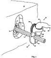
- FIG. 1 depicts concrete segment 10 including recess 12 is formed in the end of concrete segment 10.
- Post-tensioning anchor 14 may be positioned about tension member 16.
- Tension member 16 may extend through recess 12 from end of concrete segment 10.
- Tension member 16 may be held in place by wedges 18 seated within anchor 14.
- Plasma cutting torch 20 may be used for cutting tension member 16.
- plasma cutting torch 20 may use a gas source, such as a source of air, nitrogen, argon or oxygen, to an electrical power source and electrodes to generate a stream of air, nitrogen or other gaseous plasma at temperatures sufficient to cut tension member 16, for example and without limitation, from about 3,000° C - 5,000° C or more.
- the plasma torch will cut through tension member 16 more quickly than an acetylene torch, abrasive saw, or metal arm.
- Plasma cutting torch 20 may include handle 22, head 24, and cutting tip 26. Heat shield 25 may surround at least a portion of cutting tip 26. Heat shield 25 may be formed of, for example, ceramic. Plasma cutting torch 20 may also include a compressor, cylinder or other source for the gas to be formed into the plasma, a source of electrical power and an electrode for converting the gas into a gaseous plasma. The electrode may be disposed in handle 22, head 24, or in another portion of plasma cutting torch 20. In certain embodiments, plasma cutting torch 20 may have an electrical ground. The electrical ground may include, but not be limited to a metal or other conductive hand that touches tension member 16. In other embodiments, the ground may be a clamp 28, as described hereinbelow. A superheated stream of gaseous plasma is discharged from cutting tip 26. During cutting, cutting tip 26 is positioned near tension member 16. Spacing between cutting tip 26 and the surface of tension member 16 may vary.
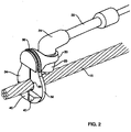
- Plasma cutting torch 20 may have a limited cutting depth. In some embodiments, cutting of tension member 16 by plasma cutting torch 20 may be performed within recess 12 in close proximity to the anchor 14. In certain embodiments, as shown in FIGs. 1 and 2 , plasma cutting torch 20 may be mounted on clamp 28 for positioning cutting tip 26 with respect to tension member 16 and anchor 14. While shown in FIGs. 1 and 2 as having a particular configuration, clamp 28 may be of any configuration for positioning cutting tip 26 within sufficient distance of tension member 16 to cut tension member 16 and within a desired distance of anchor 14.
- Clamp 28 may be releasably coupled to tension member 16, such as through bracket 30.
- Bracket 30 may be mechanically coupled to head 24 of plasma cutting torch 20. Bracket 30 may be sized to be friction fitted around head 24 or may be permanently attached to head 24 or heat shield 25.
- positioners may be attached to bracket 30 so as to position cutting tip 26 at a predetermined distance from anchor 14 along the longitudinal axis of tension member 16.
- the positioners may be pair of depending jaws 32, 34. Pair of depending jaws 32, 34 may be pivotally attached to bracket 30 and biased towards a closed position by a biasing mechanism, such as spring clip 36.
- Each of depending jaws 32, 34 may include semicircular relieved portion 38 at the inner edge of each of depending jaws 32, 34. When pair of depending jaws 32, 34 abut, semicircular relieved portions 38 may form a circular opening through which the tension member 16 may be received. As shown in FIG. 2 , the bottom portion of each depending jaw 32, 34 may have sloping area 40. Sloping area 40 may bias depending jaws 32, 34 open when the depending jaws 32, 34 are pushed against tension member 16. Once the tension member 16 is received within the circular opening, depending jaws 32, 34 may close around tension member 16.
- depending jaws 32, 34 when closed around the tension member 16 may act as shield means for protecting anchor 14 and wedges 18 from hot metal splatter during a cutting operation using plasma cutting torch 20.
- depending jaws 32, 34 may be shaped to conform to the shape of recess 12.
- depending jaws 32, 34 may be positioned around the tension member 16, outside recess 12. Depending jaws 32, 34 may be biased into a closed position by spring clip 36. Depending jaws 32, 34 with head 24 attached pivotally thereto by the bracket 30, may be moved longitudinally along tension member 16 until depending jaws 32, 34 are received within recess 12. Cutting tip 26 may then be positioned both angularly and longitudinally about tension member 16 and anchor 14 for cutting the tension member 16.
- tension member 16 may be encased by a sheath. As depicted in FIG. 1 , the sheath has been removed prior to placement of clamp 28. In other embodiments, clamp 28 may be placed over the sheath.
- cutting tip 26 may be moved through an arc substantially perpendicular to the longitudinal axis of tension member 16.
- the plasma stream may cut through the entire thickness of tension member 16.
- the sheath may be melted by the plasma stream. After cutting, the severed end of tension member 16, plasma cutting torch 20 and clamp 28 may then be removed.
- recess 12 may be asymmetrically shaped to permit pivoting of plasma cutting torch 20 attached to the clamp, so that the plasma stream may be rotated through an arc for cutting tension member 16, while the clamp 28 remains within recess 12.
- the asymmetrically-shaped recess 12 may include an upper portion for receiving head 24, and a lower portion for permitting rotation of cutting tip 26 through an area of approximately 90° (about 45° on each side of the longitudinal axis of tension member 16).
- An asymmetric shape of recess 12 may allow a recess of smaller area than a symmetric-shape recess 12, thereby requiring less grout for subsequent filling and sealing of recess 12.
- the plasma cutting torch 20 may be rotated about the tension member 16.
- recess 12 may be made substantially larger, as rotation of a larger arc with head 24 of plasma cutting torch 20 may be required.
- FIG. 3 is a schematic of PT plant plasma strand cutter 100 consistent with at least one embodiment of the present disclosure.
- PT plasma strand cutter includes power source 120, actuating device 140, and plasma torch 160.
- Power source 120 may supply the gas to be formed into the plasma, and a source of electrical power for converting the gas into a gaseous plasma.
- power source 120 may supply either hydraulic power or electrical power to actuate actuating device 140.
- Electrical power and/or the gas to be formed into plasma may be delivered to plasma torch 160 through umbilical 122.
- Actuating device 140 may be, for example and without limitation, a piston or a linear actuator.
- power source 120 may supply hydraulic power or electromechanical power to actuating device 140.
- power source 120 may be mounted on platform 170.
- PT plasma strand cutter 100 may be paired with strand puller 200.
- Plasma torch 160 may be a plasma pencil torch.
- FIG. 4 is a view of PT plant plasma strand cutter 100 focused on plasma torch 160.
- plasma torch 160 includes attachment point 162 on which actuating device 140 is mounted. While shown as a cylinder extending from plasma torch 160, attachment point may be any device upon which actuating device 140 may be mounted.
- FIG. 4 further depicts pivot 164. Pivot 164 of plasma torch 160 may be adapted to allow rotation of plasma torch 160 as described hereinbelow.
- FIG. 4 also depicts strand 220 positioned to be cut by plasma torch 160. As shown in FIG. 4 , strand 220 may rest or be in proximity to platform 170. As further shown in FIG. 4 , platform 170 may include guide 172 to assist an operator in placement of strand 220 and to guide rotation of plasma torch 160.
- FIG. 5 is a schematic view of tip 166 of plasma torch 160 while in operation, depicting plasma flame 184 having cut strand 220.
- FIG. 5 further depicts torch cap 168.
- FIG. 6 is a schematic view of tip 166 of plasma torch 160. As shown in FIG. 6 , torch cap 168 terminates in electrode 169.
- strand puller 200 advances strand 220 to platform 170.
- Strand 220 is positioned by the operator using guide 172.
- Plasma torch 160 may be powered, extending plasma flame 184 from tip 166 of plasma torch 160.
- Plasma torch 160 may be rotated above pivot 164 using actuating device 140, thereby severing strand 220.
Landscapes
- Engineering & Computer Science (AREA)
- Physics & Mathematics (AREA)
- Mechanical Engineering (AREA)
- Plasma & Fusion (AREA)
- Optics & Photonics (AREA)
- Arc Welding In General (AREA)
- Placing Or Removing Of Piles Or Sheet Piles, Or Accessories Thereof (AREA)
Claims (10)
- System zum Schneiden eines Strangs (220) in einer Vorspannanlage, umfassend:einen Plasmastrangschneider (100), wobei der Plasmastrangschneider (100) beinhaltet:einen Plasmabrenner (160), wobei der Plasmabrenner (160) einen Drehpunkt (164) und einen Befestigungspunkt (162) beinhaltet;eine Betätigungsvorrichtung (140), wobei die Betätigungsvorrichtung (140) auf dem Plasmabrenner (160) an dem Befestigungspunkt (162) montiert ist;ein Netzteil (120), wobei das Netzteil (120) mit dem Plasmabrenner (160) und der Betätigungsvorrichtung (140) verbunden ist;eine Strangzugvorrichtung (200), wobei die Strangzugvorrichtung (200) mit dem Plasmastrangschneider (100) gepaart ist; undeine Plattform (170), wobei die Plattform (170) positioniert ist, um eine Auflage für den Strang (220) oder in dessen unmittelbarer Nähe bereitzustellen, wobei die Plattform (170) eine Führung (172) beinhaltet, die die Platzierung des Strangs (220) steuert und die Drehung des Plasmabrenners (160) steuert;
wobei die Strangzugvorrichtung (200) positioniert ist, um den Strang (220) zu der Plattform (170) vorzuschieben. - System nach Anspruch 1, wobei das Netzteil (120) dafür ausgelegt ist, den Plasmabrenner (160) mit Gas und elektrischer Energie zu versorgen.
- System nach Anspruch 2, wobei das Netzteil (120) über ein Versorgungskabel (122) mit dem Plasmastrangschneider (100) verbunden ist.
- System nach einem der Ansprüche 1 bis 3, wobei die Betätigungsvorrichtung (140) ein Kolben- oder Linearaktor ist.
- System nach einem der Ansprüche 1 bis 4, wobei der Drehpunkt (164) dafür ausgelegt ist, die Drehung des Plasmabrenners (160) zu ermöglichen.
- System nach einem der Ansprüche 1 bis 5, wobei der Plasmabrenner (160) eine Brennerkappe (168) beinhaltet.
- System nach Anspruch 6, wobei die Plasmabrennerkappe (168) in einer Elektrode (169) endet.
- Verfahren zum Schneiden eines Strangs (220) in einer Vorspannanlage, umfassend:Bereitstellen eines Systems zum Schneiden eines Strangs (220) in einer Vorspannanlage,umfassend:einen Plasmastrangschneider (100), wobei der Plasmastrangschneider (100) beinhaltet:einen Plasmabrenner (160), wobei der Plasmabrenner (160) einen Drehpunkt (164) und einen Befestigungspunkt (162) beinhaltet;eine Betätigungsvorrichtung (140), wobei die Betätigungsvorrichtung (140) auf dem Plasmabrenner (160) an dem Befestigungspunkt (162) montiert ist;ein Netzteil (120), wobei das Netzteil (120) mit dem Plasmabrenner (160) und der Betätigungsvorrichtung (140) verbunden ist;eine Strangzugvorrichtung (200), wobei die Strangzugvorrichtung (200) mit dem Plasmastrangschneider (100) gepaart ist; undeine Plattform (170), wobei die Plattform (170) positioniert ist, um eine Auflage für den Strang (220) oder in dessen unmittelbarer Nähe bereitzustellen, wobei die Plattform (170) eine Führung (172) beinhaltet, die die Platzierung des Strangs (220) steuert und die Drehung des Plasmabrenners (160) steuert;
wobei die Strangzugvorrichtung (200) positioniert ist, um den Strang (220) zu der Plattform (170) vorzuschieben;Verwenden der Strangzugvorrichtung (200), um den Strang (220) zu der Plattform (170) vorzuschieben;Verwenden der Führung (172), um den Strang (220) zu positionieren;Einschalten des Plasmabrenners (160);Ausfahren einer Plasmaflamme (184) aus dem Plasmabrenner (160);Drehen des Plasmabrenners (160) um den Drehpunkt (164); undDurchtrennen des Strangs (220) unter Verwendung der Plasmaflamme (184). - Verfahren nach Anspruch 8, wobei der Schritt des Drehens des Plasmabrenners (160) von einer Betätigungsvorrichtung (140) durchgeführt wird.
- Verfahren nach Anspruch 8 oder Anspruch 9, wobei der Schritt des Positionierens des Strangs (220) an einer Führung (172) auf der Plattform (170) durchgeführt wird.
Applications Claiming Priority (1)
| Application Number | Priority Date | Filing Date | Title |
|---|---|---|---|
| US201662409088P | 2016-10-17 | 2016-10-17 |
Publications (2)
| Publication Number | Publication Date |
|---|---|
| EP3323548A1 EP3323548A1 (de) | 2018-05-23 |
| EP3323548B1 true EP3323548B1 (de) | 2022-12-07 |
Family
ID=60138226
Family Applications (1)
| Application Number | Title | Priority Date | Filing Date |
|---|---|---|---|
| EP17196799.5A Active EP3323548B1 (de) | 2016-10-17 | 2017-10-17 | Plasmaschneider für vorgespannte kabel |
Country Status (4)
| Country | Link |
|---|---|
| US (1) | US10717159B2 (de) |
| EP (1) | EP3323548B1 (de) |
| CA (1) | CA2982635C (de) |
| ES (1) | ES2937290T3 (de) |
Citations (2)
| Publication number | Priority date | Publication date | Assignee | Title |
|---|---|---|---|---|
| JPS62199238A (ja) * | 1986-02-27 | 1987-09-02 | Teraura Kaichiro | 金属撚線索の切断方法 |
| JPH05185174A (ja) * | 1991-12-13 | 1993-07-27 | Olympus Optical Co Ltd | 細線切断方法 |
Family Cites Families (21)
| Publication number | Priority date | Publication date | Assignee | Title |
|---|---|---|---|---|
| US4896470A (en) | 1988-04-21 | 1990-01-30 | Varitech Industries, Inc. | Tendon tensioning anchor |
| US5072558A (en) | 1988-04-21 | 1991-12-17 | Varitech Industries, Inc. | Post-tension anchor system |
| US5436425A (en) * | 1994-06-27 | 1995-07-25 | Sorkin; Felix L. | Method and apparatus for plasma cable cutting |
| US5720139A (en) | 1996-02-26 | 1998-02-24 | Sorkin; Felix L. | Method and apparatus for installing a multi-strand anchorage system |
| GB2318537B (en) * | 1996-10-23 | 1999-03-31 | Sansha Electric Mfg Co Ltd | Air plasma arc cutter |
| US5897102A (en) | 1998-01-15 | 1999-04-27 | Sorkin; Felix L. | Pocketformer apparatus for a post-tension anchor system |
| US6040546A (en) * | 1999-05-23 | 2000-03-21 | Sorkin; Felix L. | Method and apparatus for cutting a tendon used in a post-tension anchor system |
| US6393781B1 (en) | 2000-03-13 | 2002-05-28 | Felix L. Sorkin | Pocketformer apparatus for a post-tension anchor system and method of using same |
| US6380508B1 (en) * | 2000-07-12 | 2002-04-30 | Felix L. Sorkin | Apparatus and method for severing a tendon used in post-tension construction |
| US6817148B1 (en) | 2000-08-28 | 2004-11-16 | Felix L. Sorkin | Corrosion protection seal for an anchor of a post-tension system |
| US20030052095A1 (en) | 2001-09-19 | 2003-03-20 | Hypertherm, Inc. | Plasma process and apparatus for cutting a cable |
| US7176404B2 (en) * | 2003-01-22 | 2007-02-13 | Illinois Tool Works Inc. | System for quick disconnect of torch from power and gas supply unit |
| US7596915B2 (en) | 2006-06-20 | 2009-10-06 | Davis Energy Group, Inc. | Slab edge insulating form system and methods |
| US8710396B2 (en) * | 2006-07-27 | 2014-04-29 | Illinois Tool Works Inc. | Method and apparatus for automatically controlling gas pressure for a plasma cutter |
| US8069624B1 (en) | 2007-10-17 | 2011-12-06 | Sorkin Felix L | Pocketformer assembly for a post-tension anchor system |
| USD615219S1 (en) | 2008-04-29 | 2010-05-04 | Sorkin Felix L | Pocketformer |
| US8251344B1 (en) | 2008-05-30 | 2012-08-28 | Sorkin Felix L | Pocketformer with flow channel |
| US8946584B2 (en) * | 2011-05-26 | 2015-02-03 | Retro Systems, LLC | Angled cut height control system for a plasma arch torch |
| US9604416B2 (en) | 2014-05-19 | 2017-03-28 | Felix Sorkin | Method of forming a post-tensioned concrete member utilizing a pocket former with keyway former |
| WO2015178959A1 (en) | 2014-05-19 | 2015-11-26 | Felix Sorkin | Modified permanent cap |
| US9982434B1 (en) * | 2015-06-04 | 2018-05-29 | Structural Technologies Ip, Llc | Encapsulated anchor devices, systems, and methods |
-
2017
- 2017-10-16 CA CA2982635A patent/CA2982635C/en active Active
- 2017-10-17 US US15/785,970 patent/US10717159B2/en active Active
- 2017-10-17 ES ES17196799T patent/ES2937290T3/es active Active
- 2017-10-17 EP EP17196799.5A patent/EP3323548B1/de active Active
Patent Citations (2)
| Publication number | Priority date | Publication date | Assignee | Title |
|---|---|---|---|---|
| JPS62199238A (ja) * | 1986-02-27 | 1987-09-02 | Teraura Kaichiro | 金属撚線索の切断方法 |
| JPH05185174A (ja) * | 1991-12-13 | 1993-07-27 | Olympus Optical Co Ltd | 細線切断方法 |
Also Published As
| Publication number | Publication date |
|---|---|
| EP3323548A1 (de) | 2018-05-23 |
| CA2982635C (en) | 2020-12-29 |
| CA2982635A1 (en) | 2018-04-17 |
| ES2937290T3 (es) | 2023-03-27 |
| US10717159B2 (en) | 2020-07-21 |
| US20180104774A1 (en) | 2018-04-19 |
Similar Documents
| Publication | Publication Date | Title |
|---|---|---|
| CN102395444B (zh) | 用于导轨焊接的焊接头 | |
| CN113309110B (zh) | 基坑位移自动监测系统和方法 | |
| US10717159B2 (en) | Plasma cutter for post tension plant | |
| US6380508B1 (en) | Apparatus and method for severing a tendon used in post-tension construction | |
| US5436425A (en) | Method and apparatus for plasma cable cutting | |
| EP4029619A1 (de) | Tragbare schneideanlage | |
| US3644611A (en) | Art of removing fiber forms from concrete columns | |
| US10857631B2 (en) | Spark capture system for use with cutting torch | |
| US6040546A (en) | Method and apparatus for cutting a tendon used in a post-tension anchor system | |
| CN221935242U (zh) | 一种钢绞线不锈钢切割圆环装置 | |
| US20190226218A1 (en) | Form Tie System | |
| US20150052761A1 (en) | Cutting tool | |
| US12479052B2 (en) | Method and apparatus for plasma cable cutting | |
| US20100071528A1 (en) | Device for stripping sheathing on unbonded post-tensioning tendons | |
| KR101179055B1 (ko) | 연약지반용 앵커 조립체 | |
| US20070094875A1 (en) | Releaseable pike pole | |
| EP3892788B1 (de) | Schervorrichtung und scherverfahren für spannglieder | |
| US20190191640A1 (en) | Method of felling a tree | |
| CN202196985U (zh) | 高压电缆线半导体切割器 | |
| JP4610540B2 (ja) | トンネル覆工コンクリート打設方法及び打設構造 | |
| US20250153255A1 (en) | In-line pocket shear | |
| CA3001586C (en) | Spark capture system for use with cutting torch | |
| JP6257372B2 (ja) | コンクリート溝形成装置及び該装置を用いた既設コンクリート柱の耐震補強工法 | |
| EP3118386A1 (de) | Keil für nachträgliches spannen von bewehrungskabeln | |
| JP7245507B2 (ja) | ケーブルカッター |
Legal Events
| Date | Code | Title | Description |
|---|---|---|---|
| PUAI | Public reference made under article 153(3) epc to a published international application that has entered the european phase |
Free format text: ORIGINAL CODE: 0009012 |
|
| STAA | Information on the status of an ep patent application or granted ep patent |
Free format text: STATUS: THE APPLICATION HAS BEEN PUBLISHED |
|
| AK | Designated contracting states |
Kind code of ref document: A1 Designated state(s): AL AT BE BG CH CY CZ DE DK EE ES FI FR GB GR HR HU IE IS IT LI LT LU LV MC MK MT NL NO PL PT RO RS SE SI SK SM TR |
|
| AX | Request for extension of the european patent |
Extension state: BA ME |
|
| STAA | Information on the status of an ep patent application or granted ep patent |
Free format text: STATUS: REQUEST FOR EXAMINATION WAS MADE |
|
| 17P | Request for examination filed |
Effective date: 20181026 |
|
| RBV | Designated contracting states (corrected) |
Designated state(s): AL AT BE BG CH CY CZ DE DK EE ES FI FR GB GR HR HU IE IS IT LI LT LU LV MC MK MT NL NO PL PT RO RS SE SI SK SM TR |
|
| STAA | Information on the status of an ep patent application or granted ep patent |
Free format text: STATUS: EXAMINATION IS IN PROGRESS |
|
| 17Q | First examination report despatched |
Effective date: 20210601 |
|
| GRAP | Despatch of communication of intention to grant a patent |
Free format text: ORIGINAL CODE: EPIDOSNIGR1 |
|
| STAA | Information on the status of an ep patent application or granted ep patent |
Free format text: STATUS: GRANT OF PATENT IS INTENDED |
|
| INTG | Intention to grant announced |
Effective date: 20220517 |
|
| GRAS | Grant fee paid |
Free format text: ORIGINAL CODE: EPIDOSNIGR3 |
|
| GRAA | (expected) grant |
Free format text: ORIGINAL CODE: 0009210 |
|
| STAA | Information on the status of an ep patent application or granted ep patent |
Free format text: STATUS: THE PATENT HAS BEEN GRANTED |
|
| AK | Designated contracting states |
Kind code of ref document: B1 Designated state(s): AL AT BE BG CH CY CZ DE DK EE ES FI FR GB GR HR HU IE IS IT LI LT LU LV MC MK MT NL NO PL PT RO RS SE SI SK SM TR |
|
| REG | Reference to a national code |
Ref country code: GB Ref legal event code: FG4D |
|
| REG | Reference to a national code |
Ref country code: CH Ref legal event code: EP Ref country code: AT Ref legal event code: REF Ref document number: 1536007 Country of ref document: AT Kind code of ref document: T Effective date: 20221215 |
|
| REG | Reference to a national code |
Ref country code: DE Ref legal event code: R096 Ref document number: 602017064331 Country of ref document: DE |
|
| REG | Reference to a national code |
Ref country code: IE Ref legal event code: FG4D |
|
| REG | Reference to a national code |
Ref country code: LT Ref legal event code: MG9D Ref country code: ES Ref legal event code: FG2A Ref document number: 2937290 Country of ref document: ES Kind code of ref document: T3 Effective date: 20230327 |
|
| REG | Reference to a national code |
Ref country code: NL Ref legal event code: MP Effective date: 20221207 |
|
| PG25 | Lapsed in a contracting state [announced via postgrant information from national office to epo] |
Ref country code: SE Free format text: LAPSE BECAUSE OF FAILURE TO SUBMIT A TRANSLATION OF THE DESCRIPTION OR TO PAY THE FEE WITHIN THE PRESCRIBED TIME-LIMIT Effective date: 20221207 Ref country code: NO Free format text: LAPSE BECAUSE OF FAILURE TO SUBMIT A TRANSLATION OF THE DESCRIPTION OR TO PAY THE FEE WITHIN THE PRESCRIBED TIME-LIMIT Effective date: 20230307 Ref country code: LT Free format text: LAPSE BECAUSE OF FAILURE TO SUBMIT A TRANSLATION OF THE DESCRIPTION OR TO PAY THE FEE WITHIN THE PRESCRIBED TIME-LIMIT Effective date: 20221207 Ref country code: FI Free format text: LAPSE BECAUSE OF FAILURE TO SUBMIT A TRANSLATION OF THE DESCRIPTION OR TO PAY THE FEE WITHIN THE PRESCRIBED TIME-LIMIT Effective date: 20221207 |
|
| REG | Reference to a national code |
Ref country code: AT Ref legal event code: MK05 Ref document number: 1536007 Country of ref document: AT Kind code of ref document: T Effective date: 20221207 |
|
| PG25 | Lapsed in a contracting state [announced via postgrant information from national office to epo] |
Ref country code: RS Free format text: LAPSE BECAUSE OF FAILURE TO SUBMIT A TRANSLATION OF THE DESCRIPTION OR TO PAY THE FEE WITHIN THE PRESCRIBED TIME-LIMIT Effective date: 20221207 Ref country code: PL Free format text: LAPSE BECAUSE OF FAILURE TO SUBMIT A TRANSLATION OF THE DESCRIPTION OR TO PAY THE FEE WITHIN THE PRESCRIBED TIME-LIMIT Effective date: 20221207 Ref country code: LV Free format text: LAPSE BECAUSE OF FAILURE TO SUBMIT A TRANSLATION OF THE DESCRIPTION OR TO PAY THE FEE WITHIN THE PRESCRIBED TIME-LIMIT Effective date: 20221207 Ref country code: HR Free format text: LAPSE BECAUSE OF FAILURE TO SUBMIT A TRANSLATION OF THE DESCRIPTION OR TO PAY THE FEE WITHIN THE PRESCRIBED TIME-LIMIT Effective date: 20221207 Ref country code: GR Free format text: LAPSE BECAUSE OF FAILURE TO SUBMIT A TRANSLATION OF THE DESCRIPTION OR TO PAY THE FEE WITHIN THE PRESCRIBED TIME-LIMIT Effective date: 20230308 |
|
| PG25 | Lapsed in a contracting state [announced via postgrant information from national office to epo] |
Ref country code: NL Free format text: LAPSE BECAUSE OF FAILURE TO SUBMIT A TRANSLATION OF THE DESCRIPTION OR TO PAY THE FEE WITHIN THE PRESCRIBED TIME-LIMIT Effective date: 20221207 |
|
| P01 | Opt-out of the competence of the unified patent court (upc) registered |
Effective date: 20230613 |
|
| PG25 | Lapsed in a contracting state [announced via postgrant information from national office to epo] |
Ref country code: SM Free format text: LAPSE BECAUSE OF FAILURE TO SUBMIT A TRANSLATION OF THE DESCRIPTION OR TO PAY THE FEE WITHIN THE PRESCRIBED TIME-LIMIT Effective date: 20221207 Ref country code: RO Free format text: LAPSE BECAUSE OF FAILURE TO SUBMIT A TRANSLATION OF THE DESCRIPTION OR TO PAY THE FEE WITHIN THE PRESCRIBED TIME-LIMIT Effective date: 20221207 Ref country code: PT Free format text: LAPSE BECAUSE OF FAILURE TO SUBMIT A TRANSLATION OF THE DESCRIPTION OR TO PAY THE FEE WITHIN THE PRESCRIBED TIME-LIMIT Effective date: 20230410 Ref country code: EE Free format text: LAPSE BECAUSE OF FAILURE TO SUBMIT A TRANSLATION OF THE DESCRIPTION OR TO PAY THE FEE WITHIN THE PRESCRIBED TIME-LIMIT Effective date: 20221207 Ref country code: CZ Free format text: LAPSE BECAUSE OF FAILURE TO SUBMIT A TRANSLATION OF THE DESCRIPTION OR TO PAY THE FEE WITHIN THE PRESCRIBED TIME-LIMIT Effective date: 20221207 Ref country code: AT Free format text: LAPSE BECAUSE OF FAILURE TO SUBMIT A TRANSLATION OF THE DESCRIPTION OR TO PAY THE FEE WITHIN THE PRESCRIBED TIME-LIMIT Effective date: 20221207 |
|
| PG25 | Lapsed in a contracting state [announced via postgrant information from national office to epo] |
Ref country code: SK Free format text: LAPSE BECAUSE OF FAILURE TO SUBMIT A TRANSLATION OF THE DESCRIPTION OR TO PAY THE FEE WITHIN THE PRESCRIBED TIME-LIMIT Effective date: 20221207 Ref country code: IS Free format text: LAPSE BECAUSE OF FAILURE TO SUBMIT A TRANSLATION OF THE DESCRIPTION OR TO PAY THE FEE WITHIN THE PRESCRIBED TIME-LIMIT Effective date: 20230407 Ref country code: AL Free format text: LAPSE BECAUSE OF FAILURE TO SUBMIT A TRANSLATION OF THE DESCRIPTION OR TO PAY THE FEE WITHIN THE PRESCRIBED TIME-LIMIT Effective date: 20221207 |
|
| REG | Reference to a national code |
Ref country code: DE Ref legal event code: R097 Ref document number: 602017064331 Country of ref document: DE |
|
| PLBE | No opposition filed within time limit |
Free format text: ORIGINAL CODE: 0009261 |
|
| STAA | Information on the status of an ep patent application or granted ep patent |
Free format text: STATUS: NO OPPOSITION FILED WITHIN TIME LIMIT |
|
| PG25 | Lapsed in a contracting state [announced via postgrant information from national office to epo] |
Ref country code: DK Free format text: LAPSE BECAUSE OF FAILURE TO SUBMIT A TRANSLATION OF THE DESCRIPTION OR TO PAY THE FEE WITHIN THE PRESCRIBED TIME-LIMIT Effective date: 20221207 |
|
| 26N | No opposition filed |
Effective date: 20230908 |
|
| PG25 | Lapsed in a contracting state [announced via postgrant information from national office to epo] |
Ref country code: SI Free format text: LAPSE BECAUSE OF FAILURE TO SUBMIT A TRANSLATION OF THE DESCRIPTION OR TO PAY THE FEE WITHIN THE PRESCRIBED TIME-LIMIT Effective date: 20221207 |
|
| PG25 | Lapsed in a contracting state [announced via postgrant information from national office to epo] |
Ref country code: MC Free format text: LAPSE BECAUSE OF FAILURE TO SUBMIT A TRANSLATION OF THE DESCRIPTION OR TO PAY THE FEE WITHIN THE PRESCRIBED TIME-LIMIT Effective date: 20221207 |
|
| REG | Reference to a national code |
Ref country code: CH Ref legal event code: PL |
|
| REG | Reference to a national code |
Ref country code: BE Ref legal event code: MM Effective date: 20231031 |
|
| PG25 | Lapsed in a contracting state [announced via postgrant information from national office to epo] |
Ref country code: LU Free format text: LAPSE BECAUSE OF NON-PAYMENT OF DUE FEES Effective date: 20231017 |
|
| PG25 | Lapsed in a contracting state [announced via postgrant information from national office to epo] |
Ref country code: LU Free format text: LAPSE BECAUSE OF NON-PAYMENT OF DUE FEES Effective date: 20231017 |
|
| PG25 | Lapsed in a contracting state [announced via postgrant information from national office to epo] |
Ref country code: CH Free format text: LAPSE BECAUSE OF NON-PAYMENT OF DUE FEES Effective date: 20231031 |
|
| PG25 | Lapsed in a contracting state [announced via postgrant information from national office to epo] |
Ref country code: CH Free format text: LAPSE BECAUSE OF NON-PAYMENT OF DUE FEES Effective date: 20231031 |
|
| PG25 | Lapsed in a contracting state [announced via postgrant information from national office to epo] |
Ref country code: BE Free format text: LAPSE BECAUSE OF NON-PAYMENT OF DUE FEES Effective date: 20231031 |
|
| PG25 | Lapsed in a contracting state [announced via postgrant information from national office to epo] |
Ref country code: IE Free format text: LAPSE BECAUSE OF NON-PAYMENT OF DUE FEES Effective date: 20231017 |
|
| PG25 | Lapsed in a contracting state [announced via postgrant information from national office to epo] |
Ref country code: IE Free format text: LAPSE BECAUSE OF NON-PAYMENT OF DUE FEES Effective date: 20231017 |
|
| PG25 | Lapsed in a contracting state [announced via postgrant information from national office to epo] |
Ref country code: BG Free format text: LAPSE BECAUSE OF FAILURE TO SUBMIT A TRANSLATION OF THE DESCRIPTION OR TO PAY THE FEE WITHIN THE PRESCRIBED TIME-LIMIT Effective date: 20221207 |
|
| PG25 | Lapsed in a contracting state [announced via postgrant information from national office to epo] |
Ref country code: BG Free format text: LAPSE BECAUSE OF FAILURE TO SUBMIT A TRANSLATION OF THE DESCRIPTION OR TO PAY THE FEE WITHIN THE PRESCRIBED TIME-LIMIT Effective date: 20221207 |
|
| PG25 | Lapsed in a contracting state [announced via postgrant information from national office to epo] |
Ref country code: CY Free format text: LAPSE BECAUSE OF FAILURE TO SUBMIT A TRANSLATION OF THE DESCRIPTION OR TO PAY THE FEE WITHIN THE PRESCRIBED TIME-LIMIT; INVALID AB INITIO Effective date: 20171017 |
|
| PG25 | Lapsed in a contracting state [announced via postgrant information from national office to epo] |
Ref country code: HU Free format text: LAPSE BECAUSE OF FAILURE TO SUBMIT A TRANSLATION OF THE DESCRIPTION OR TO PAY THE FEE WITHIN THE PRESCRIBED TIME-LIMIT; INVALID AB INITIO Effective date: 20171017 |
|
| PG25 | Lapsed in a contracting state [announced via postgrant information from national office to epo] |
Ref country code: TR Free format text: LAPSE BECAUSE OF FAILURE TO SUBMIT A TRANSLATION OF THE DESCRIPTION OR TO PAY THE FEE WITHIN THE PRESCRIBED TIME-LIMIT Effective date: 20221207 |
|
| PGFP | Annual fee paid to national office [announced via postgrant information from national office to epo] |
Ref country code: DE Payment date: 20251031 Year of fee payment: 9 |
|
| PGFP | Annual fee paid to national office [announced via postgrant information from national office to epo] |
Ref country code: GB Payment date: 20251031 Year of fee payment: 9 |
|
| PGFP | Annual fee paid to national office [announced via postgrant information from national office to epo] |
Ref country code: IT Payment date: 20251029 Year of fee payment: 9 |
|
| PGFP | Annual fee paid to national office [announced via postgrant information from national office to epo] |
Ref country code: FR Payment date: 20251028 Year of fee payment: 9 |
|
| PGFP | Annual fee paid to national office [announced via postgrant information from national office to epo] |
Ref country code: ES Payment date: 20251105 Year of fee payment: 9 |