EP3323447A1 - Infusion pump - Google Patents
Infusion pump Download PDFInfo
- Publication number
- EP3323447A1 EP3323447A1 EP17207218.3A EP17207218A EP3323447A1 EP 3323447 A1 EP3323447 A1 EP 3323447A1 EP 17207218 A EP17207218 A EP 17207218A EP 3323447 A1 EP3323447 A1 EP 3323447A1
- Authority
- EP
- European Patent Office
- Prior art keywords
- drive motor
- infusion tube
- waveform signal
- output waveform
- control unit
- Prior art date
- Legal status (The legal status is an assumption and is not a legal conclusion. Google has not performed a legal analysis and makes no representation as to the accuracy of the status listed.)
- Granted
Links
Images




Classifications
-
- A—HUMAN NECESSITIES
- A61—MEDICAL OR VETERINARY SCIENCE; HYGIENE
- A61M—DEVICES FOR INTRODUCING MEDIA INTO, OR ONTO, THE BODY; DEVICES FOR TRANSDUCING BODY MEDIA OR FOR TAKING MEDIA FROM THE BODY; DEVICES FOR PRODUCING OR ENDING SLEEP OR STUPOR
- A61M5/00—Devices for bringing media into the body in a subcutaneous, intra-vascular or intramuscular way; Accessories therefor, e.g. filling or cleaning devices, arm-rests
- A61M5/14—Infusion devices, e.g. infusing by gravity; Blood infusion; Accessories therefor
- A61M5/142—Pressure infusion, e.g. using pumps
- A61M5/14212—Pumping with an aspiration and an expulsion action
- A61M5/14228—Pumping with an aspiration and an expulsion action with linear peristaltic action, i.e. comprising at least three pressurising members or a helical member
-
- A—HUMAN NECESSITIES
- A61—MEDICAL OR VETERINARY SCIENCE; HYGIENE
- A61M—DEVICES FOR INTRODUCING MEDIA INTO, OR ONTO, THE BODY; DEVICES FOR TRANSDUCING BODY MEDIA OR FOR TAKING MEDIA FROM THE BODY; DEVICES FOR PRODUCING OR ENDING SLEEP OR STUPOR
- A61M5/00—Devices for bringing media into the body in a subcutaneous, intra-vascular or intramuscular way; Accessories therefor, e.g. filling or cleaning devices, arm-rests
- A61M5/14—Infusion devices, e.g. infusing by gravity; Blood infusion; Accessories therefor
- A61M5/168—Means for controlling media flow to the body or for metering media to the body, e.g. drip meters, counters ; Monitoring media flow to the body
- A61M5/172—Means for controlling media flow to the body or for metering media to the body, e.g. drip meters, counters ; Monitoring media flow to the body electrical or electronic
-
- A—HUMAN NECESSITIES
- A61—MEDICAL OR VETERINARY SCIENCE; HYGIENE
- A61M—DEVICES FOR INTRODUCING MEDIA INTO, OR ONTO, THE BODY; DEVICES FOR TRANSDUCING BODY MEDIA OR FOR TAKING MEDIA FROM THE BODY; DEVICES FOR PRODUCING OR ENDING SLEEP OR STUPOR
- A61M5/00—Devices for bringing media into the body in a subcutaneous, intra-vascular or intramuscular way; Accessories therefor, e.g. filling or cleaning devices, arm-rests
- A61M5/14—Infusion devices, e.g. infusing by gravity; Blood infusion; Accessories therefor
- A61M5/142—Pressure infusion, e.g. using pumps
- A61M5/14212—Pumping with an aspiration and an expulsion action
- A61M5/14216—Reciprocating piston type
- A61M5/1422—Reciprocating piston type with double acting or multiple pistons
-
- A—HUMAN NECESSITIES
- A61—MEDICAL OR VETERINARY SCIENCE; HYGIENE
- A61M—DEVICES FOR INTRODUCING MEDIA INTO, OR ONTO, THE BODY; DEVICES FOR TRANSDUCING BODY MEDIA OR FOR TAKING MEDIA FROM THE BODY; DEVICES FOR PRODUCING OR ENDING SLEEP OR STUPOR
- A61M5/00—Devices for bringing media into the body in a subcutaneous, intra-vascular or intramuscular way; Accessories therefor, e.g. filling or cleaning devices, arm-rests
- A61M5/14—Infusion devices, e.g. infusing by gravity; Blood infusion; Accessories therefor
- A61M5/142—Pressure infusion, e.g. using pumps
- A61M5/14244—Pressure infusion, e.g. using pumps adapted to be carried by the patient, e.g. portable on the body
- A61M5/14276—Pressure infusion, e.g. using pumps adapted to be carried by the patient, e.g. portable on the body specially adapted for implantation
-
- G—PHYSICS
- G01—MEASURING; TESTING
- G01D—MEASURING NOT SPECIALLY ADAPTED FOR A SPECIFIC VARIABLE; ARRANGEMENTS FOR MEASURING TWO OR MORE VARIABLES NOT COVERED IN A SINGLE OTHER SUBCLASS; TARIFF METERING APPARATUS; MEASURING OR TESTING NOT OTHERWISE PROVIDED FOR
- G01D5/00—Mechanical means for transferring the output of a sensing member; Means for converting the output of a sensing member to another variable where the form or nature of the sensing member does not constrain the means for converting; Transducers not specially adapted for a specific variable
- G01D5/12—Mechanical means for transferring the output of a sensing member; Means for converting the output of a sensing member to another variable where the form or nature of the sensing member does not constrain the means for converting; Transducers not specially adapted for a specific variable using electric or magnetic means
- G01D5/14—Mechanical means for transferring the output of a sensing member; Means for converting the output of a sensing member to another variable where the form or nature of the sensing member does not constrain the means for converting; Transducers not specially adapted for a specific variable using electric or magnetic means influencing the magnitude of a current or voltage
- G01D5/20—Mechanical means for transferring the output of a sensing member; Means for converting the output of a sensing member to another variable where the form or nature of the sensing member does not constrain the means for converting; Transducers not specially adapted for a specific variable using electric or magnetic means influencing the magnitude of a current or voltage by varying inductance, e.g. by a movable armature
-
- A—HUMAN NECESSITIES
- A61—MEDICAL OR VETERINARY SCIENCE; HYGIENE
- A61M—DEVICES FOR INTRODUCING MEDIA INTO, OR ONTO, THE BODY; DEVICES FOR TRANSDUCING BODY MEDIA OR FOR TAKING MEDIA FROM THE BODY; DEVICES FOR PRODUCING OR ENDING SLEEP OR STUPOR
- A61M5/00—Devices for bringing media into the body in a subcutaneous, intra-vascular or intramuscular way; Accessories therefor, e.g. filling or cleaning devices, arm-rests
- A61M5/14—Infusion devices, e.g. infusing by gravity; Blood infusion; Accessories therefor
- A61M5/168—Means for controlling media flow to the body or for metering media to the body, e.g. drip meters, counters ; Monitoring media flow to the body
- A61M5/16831—Monitoring, detecting, signalling or eliminating infusion flow anomalies
- A61M2005/16863—Occlusion detection
-
- A—HUMAN NECESSITIES
- A61—MEDICAL OR VETERINARY SCIENCE; HYGIENE
- A61M—DEVICES FOR INTRODUCING MEDIA INTO, OR ONTO, THE BODY; DEVICES FOR TRANSDUCING BODY MEDIA OR FOR TAKING MEDIA FROM THE BODY; DEVICES FOR PRODUCING OR ENDING SLEEP OR STUPOR
- A61M5/00—Devices for bringing media into the body in a subcutaneous, intra-vascular or intramuscular way; Accessories therefor, e.g. filling or cleaning devices, arm-rests
- A61M5/14—Infusion devices, e.g. infusing by gravity; Blood infusion; Accessories therefor
- A61M5/168—Means for controlling media flow to the body or for metering media to the body, e.g. drip meters, counters ; Monitoring media flow to the body
- A61M5/16831—Monitoring, detecting, signalling or eliminating infusion flow anomalies
- A61M2005/16863—Occlusion detection
- A61M2005/16868—Downstream occlusion sensors
-
- A—HUMAN NECESSITIES
- A61—MEDICAL OR VETERINARY SCIENCE; HYGIENE
- A61M—DEVICES FOR INTRODUCING MEDIA INTO, OR ONTO, THE BODY; DEVICES FOR TRANSDUCING BODY MEDIA OR FOR TAKING MEDIA FROM THE BODY; DEVICES FOR PRODUCING OR ENDING SLEEP OR STUPOR
- A61M2205/00—General characteristics of the apparatus
- A61M2205/10—General characteristics of the apparatus with powered movement mechanisms
- A61M2205/106—General characteristics of the apparatus with powered movement mechanisms reciprocating
Definitions
- the present invention relates to an infusion pump for delivering drug to a patient.
- An infusion pump is used in an intensive care unit (ICU) or the like, for example, and is adopted to perform delivering treatment of drug for a patient at relatively high accuracy for a relatively long period of time.
- a prejudged drug bag (an infusion bag) is arranged on the top of the infusion pump and an infusion tube suspended from the drug bag is interposed between a main body and an opening/closing door.
- the infusion tube is accommodated in the main body and is held therein by closing the opening/closing door.
- an outer circumferential surface of the infusion tube set in a home position is interposed between a plurality of fingers inside the main body and an inner surface of the opening/closing door.
- the infusion pump is a peristaltic infusion pump in which a drive motor operates to deliver drug by causing the plurality of fingers to sequentially press the outer circumferential surface of the infusion tube along a longitudinal direction (refer to PTL 1) .
- an infusion pump of the related art detection has been performed in a rotor of a drive motor regarding only a forward rotation.
- the rotor of the drive motor needs to be reversely rotated as mitigation treatment for the occlusion.
- no infusion pump has been proposed which detects quantity of reverse rotation of the rotor of the drive motor.
- the present invention aims to provide an infusion pump in which a forward rotation and the reverse rotation of the rotor of the drive motor can be detected together with a rotational speed thereof so as to be able to safely deliver drug to a patient.
- an infusion pump for delivering drug to a patient by causing a distal opening portion of an endovascular indwelling catheter or an indwelling needle which communicates with an infusion tube to indwell inside a vein or an intestinal tract of the patient.
- the infusion pump includes a drive motor, a liquid delivering drive unit that delivers the drug inside the infusion tube by pressing the infusion tube on account of a rotor of the drive motor in forward rotation, a rotational direction detection device that generates detection information regarding a rotational direction for judging whether the rotor of the drive motor is in the forward rotation or reverse rotation, and a control unit.
- the control unit judges whether the rotor of the drive motor is in the forward rotation or the reverse rotation based on the detection information regarding the rotational direction obtained from the rotational direction detection device.
- the control unit also judges whether or not a rotational speed of the rotor is normal.
- an infusion pump for delivering drug to a patient by causing a distal opening portion of an endovascular indwelling catheter or an indwelling needle which communicates with an infusion tube to indwell inside a vein or an intestinal tract of the patient.
- the infusion pump includes a drive motor, a liquid delivering drive unit that delivers the drug inside the infusion tube by pressing the infusion tube on account of a rotor of the drive motor in forward rotation, a rotational direction detection device that generates detection information regarding a rotational direction for judging whether the rotor of the drive motor is in the forward rotation or reverse rotation, a downstream occlusion sensor that detects whether or not the infusion tube is occluded, and a control unit.
- the control unit judges whether the rotor of the drive motor is in the forward rotation or the reverse rotation based on the detection information regarding the rotational direction obtained from the rotational direction detection device.
- the control unit also judges whether or not a rotational speed of the rotor is normal. While causing the rotational direction detection device to detect that the rotor of the drive motor is in the forward rotation, if an occlusion state is detected by the downstream occlusion sensor when delivering liquid in the forward rotation, the control unit stops the forward rotation. While causing the rotational direction detection device to detect that the rotor of the drive motor is in the reverse rotation, the control unit controls the drive motor so as to be driven in the reverse rotation until fulfilling a prejudged condition.
- the control unit can judge whether the rotor of the drive motor is in the forward rotation or the reverse rotation based on the detection information regarding the rotational direction obtained from the rotational direction detection device. Therefore, it is possible to detect the forward rotation and the reverse rotation of the rotor of the drive motor so as to be able to safely deliver drug to a patient.
- the rotational direction detection device includes an encoder plate which is fixed to the rotor of the drive motor, and an optical coupler which obtains a first output waveform signal and a second output waveform signal different from the first output waveform signal by irradiating the encoder plate with light so as to send the first output waveform signal and the second output waveform signal to the control unit as the detection information regarding the rotational direction.
- the optical coupler optically generates the first output waveform signal and the second output waveform signal so as to send to the control unit as the detection information regarding the rotational direction of the rotor.
- the optical coupler optically generates the first output waveform signal and the second output waveform signal so as to send to the control unit as the detection information regarding the rotational direction of the rotor.
- the first output waveform signal is an output waveform signal at 1X speed
- the second output waveform signal is an output waveform signal at 3X speed.
- the control unit judges whether the rotor is in the forward rotation or the reverse rotation by comparing the first output waveform signal and the second output waveform signal.
- control unit since the control unit has only to compare the first output waveform signal and the second output waveform signal, it is possible to accurately judge whether the rotor is in the forward rotation or the reverse rotation.
- the liquid delivering drive unit includes a plurality of cams which rotate on account of the forward rotation of the drive motor, and a plurality of fingers which deliver the drug inside the infusion tube while sequentially pressing the infusion tube in a longitudinal direction on account of the plurality of cams in rotation.
- the plurality of fingers can reliably deliver drug inside the infusion tube to a patient side by causing the plurality of cams to rotate forward.
- a display unit displaying information and an operation panel portion having an operation button are arranged in an upper portion of a main body of the infusion pump, and the infusion tube is arranged in a region of a lower portion of the main body of the infusion pump.
- a health care worker can perform delivering of drug by using the infusion pump while confirming the information on the display unit in the upper portion of the main body. Then, the health care worker can operate the operation button of the operation panel portion while confirming the information on the display unit in the upper portion of the main body.
- an infusion pump in which a forward rotation and a reverse rotation of a rotor of a drive motor can be detected so as to be able to safely deliver drug to a patient.
- Fig. 1 is a perspective view illustrating an infusion pump which is the preferable embodiment of the infusion pump of the present invention.
- Fig. 2 is a diagram of the infusion pump illustrated in Fig. 1 when seen in a W-direction.
- the infusion pump 1 illustrated in Figs. 1 and 2 is a continuous infusion pump which is used for a patient in infusion treatment of drug (also referred to as a drug solution) such as an anticancer drug, an anesthetic, a chemotherapeutic and the like, infusion treatment of a nutrient, a blood transfusion and the like in intensive care units (ICU, CCU, NICU) or the like, for example, at relatively high accuracy for a relatively long period of time.
- drug also referred to as a drug solution
- drug also referred to as a drug solution
- ICU intensive care units
- CCU CCU
- NICU intensive care units
- the infusion pump 1 is used to select drug to be used from a drug library and to deliver the selected drug.
- the drug library is drug information of a dosage setting group of drug including the previously registered drug names in a drug library database (DB).
- DB drug library database
- the infusion pump 1 can accurately deliver liquid to the inside of a patient P from a drug bag 170 filled with drug (or blood) 171 through a Klemme 179, an infusion tube 200, and an indwelling needle or an endovascular indwelling catheter 172 caused to indwell inside a vein of the patient P.
- Drug is also referred to as an infusion solution.
- An infusion tube is also referred to as an infusion line.
- the infusion pump 1 can accurately deliver liquid to the inside of the patient P from the bag 170 filled with a nutrient 171 through the Klemme 179, the infusion tube 200, and a catheter 172 for indwelling inside an intestinal tract.
- the infusion pump 1 has a main body cover 2 and a handle 2T.
- the handle 2T can be stretched in an N-direction and can be accommodated in a T-direction.
- the main body cover 2 is also referred to as a main body and is integrally molded with a molding resin material which is chemically resistant.
- the main body cover 2 has a drip-proof treated structure which can prevent the inside of the infusion pump 1 from being penetrated by drug even if the drug or the like is splashed over the main body cover.
- the main body cover 2 has such a drip-proof treated structure because there may be a case where the drug 171 in the drug bag 170 arranged in an upper portion is spilt, or an antiseptic solution or the like used in the vicinity thereof is splashed and adheres thereto.
- a display unit 3 and an operation panel portion 4 are arranged in an upper portion 2A of the main body cover 2.
- the display unit 3 is an image display apparatus, and a color liquid crystal display apparatus is used, for example.
- the display unit 3 can display information not only by notation in Japanese but also by notation in multiple foreign languages as necessary.
- the display unit 3 is arranged at an upper left position in the upper portion 2A of the main body cover 2, that is, on an upper side of an opening/closing cover 5.
- the upper portion 2A of the main body cover 2 is the upper half portion of the main body cover 2.
- the lower portion 2B of the main body cover 2 is the lower half portion of the main body cover 2.
- the display unit 3 for displaying information and the operation panel portion 4 including a plurality of operation buttons are arranged.
- the lower portion 2B of the main body cover 2 of the infusion pump 1 is a region in which the infusion tube 200, that is, a delivery member for delivering drug is arranged. Accordingly, a health care worker can perform delivering of drug by using the infusion pump 1 while confirming information on the display unit 3 in the upper portion 2A of the main body cover 2. Then, the health care worker can operate the operation buttons of the operation panel portion 4 while confirming the information on the display unit 3 in the upper portion 2A of the main body cover 2. Therefore, the infusion pump 1 has favorable operability.
- the display unit 3 displays a display section 3B for a planned dosage (mL) of drug, a display section 3C for an integrated dosage (mL) of drug, a display section 3D for a charge history, a display section 3E for a flow rate (mL/h) and the like.
- the aforementioned display contents are omitted in order to simplify the drawing.
- the display unit 3 can additionally display a warning message.
- the operation panel portion 4 is arranged on the right side of the display unit 3 in the upper portion 2A of the main body cover 2.
- a lamp 4A formed with an LED, blinking or being lit in green during a normal operation, and blinking or being lit in red during an abnormal operation
- a fast-delivering switch button 4B which functions as an operational indicator
- a start switch button 4C which functions as an operational indicator
- a stop switch button 4D which functions as an operational indicator
- a menu selection button 4E a power switch 4F and the like
- a power switch 4F and the like are arranged in the operation panel portion 4, for example.
- the opening/closing cover 5 as a lid member is provided in the lower portion 2B of the main body cover 2 so as to be able to be in open and closed states in an R-direction having a rotary shaft 5A as the center.
- the opening/closing cover 5 is a plate-like lid member formed to be elongated along the X-direction.
- a tube mounting portion 50 and a liquid delivering drive unit 60 are arranged inside the opening/closing cover 5.
- the infusion tube 200 made of a flexible thermoplastic resin, soft vinyl chloride or the like, for example, is set to the tube mounting portion 50. As the opening/closing cover 5 is in the closed state, the infusion tube 200 can be horizontally mounted in the tube mounting portion 50 along an X-direction (the T-direction).
- the X-direction, a Y-direction, and a Z-direction in Figs. 1 and 2 are orthogonal to each other.
- the Z-direction is a vertical direction.
- the X-direction is a transverse direction of the infusion pump 1 parallel to the T-direction which is a delivering direction.
- the Y-direction is a front-rear direction of the infusion pump 1.
- Fig. 3 is a perspective view illustrating the tube mounting portion 50 for mounting the infusion tube 200 by causing the opening/closing cover 5 of the infusion pump 1 illustrated in Figs. 1 and 2 to be in an open state.
- the tube mounting portion 50 and the liquid delivering drive unit 60 are provided on a main body lower portion 1B side of the infusion pump 1.
- the tube mounting portion 50 and the liquid delivering drive unit 60 are provided along the X-direction at a lower portion of the display unit 3 and the operation panel portion 4.
- the tube mounting portion 50 can be covered with the opening/closing cover 5 by closing the opening/closing cover 5 in a CR-direction having the rotary shaft 5A as the center.
- a health care worker can mount the infusion tube 200 in the tube mounting portion 50 and close the opening/closing cover 5 while confirming the information on the display unit 3 in the upper portion 2A of the main body cover 2. Then, the health care worker can operate the operation buttons of the operation panel portion 4 while confirming the information on the display unit 3 in the upper portion 2A of the main body cover 2. Accordingly, in medical sites, operability of the infusion pump 1 can be improved.
- the tube mounting portion 50 includes an air bubble sensor 51, an upstream occlusion sensor 52, a downstream occlusion sensor 53, a tube clamp portion 270, a first infusion tube guide portion 54 at a position on the right side, and a second infusion tube guide portion 55 at a position on the left side.
- an infusion tube setting direction display portion 150 for clearly displaying the T-direction as the proper delivering direction when setting the infusion tube 200.
- the infusion tube setting direction display portion 150 is configured to include a plurality of arrows 151.
- the infusion tube setting direction display portion 150 may be directly printed on the lower portion of the tube mounting portion 50 or may be printed on a sticker-like member so as to be pasted on the lower portion of the tube mounting portion 50.
- the infusion tube setting direction display portion 150 is arranged in order to clarify the delivering direction (the T-direction) as the proper direction for the drug 171 which is delivered through the infusion tube 200 set inside the opening/closing cover 5.
- the T-direction as the delivering direction of drug delivered through the infusion tube 200 when a health care worker undoes the opening/closing cover 5 of Fig. 3 in a CS-direction, opens the tube mounting portion 50, and causes the infusion tube 200 to be mounted in the tube mounting portion 50. Therefore, it is possible for a health care worker to be reliably prevented from erroneously mounting the infusion tube 200 in the reverse direction.
- the opening/closing cover 5 is a plate-like member made with a thin molding resin member in order to achieve weight reduction of the infusion pump 1. In this manner, the weight of the opening/closing cover 5 can be reduced, and thus, the structure thereof can be simplified.
- the opening/closing cover 5 is supported by two hinge portions 2H and 2H with respect to the main body lower portion 2B of the main body cover 2 so as to be able to be in open and closed states and to cover the tube mounting portion 50 along the CS-direction and the CR-direction having the rotary shaft 5A as the center.
- the two hinge portions 2H and 2H are arranged so as to respectively correspond to a first hook member 5D and a second hook member 5E.
- an opening/closing operation lever 260 is provided on an upper right portion of the opening/closing cover 5 on an outer surface side.
- An infusion tube pressing member 500, the first hook member 5D, and the second hook member 5E are provided inside the opening/closing cover 5.
- the infusion tube pressing member 500 is arranged as a protruding portion having an elongated rectangular and planar shape along the X-direction.
- the infusion tube pressing member 500 is at a position facing the liquid delivering drive unit 60.
- the infusion tube pressing member 500 has a flat surface in the X-direction along the liquid delivering drive unit 60.
- a portion of the infusion tube 200 is pressedly interposed between the infusion tube pressing member 500 and the liquid delivering drive unit 60 when the opening/closing cover 5 is in the closed state in the CR-direction.
- a health care worker can set the infusion tube 200 in the lower half portion of the main body of the infusion pump 1 along a horizontal direction while confirming display contents displayed on the display unit 3.
- the opening/closing cover 5 can cover the infusion tube 200.
- the first hook member 5D and the second hook member 5E are respectively and mechanically interlocked with fixing portions 1D and 1E on the main body lower portion 1B side at the same time.
- the opening/closing cover 5 maintains the tube mounting portion 50 at the main body lower portion 1B in a shut-down state.
- the first hook member 5D and the second hook member 5E including the fixing portions 1D and 1E on the main body lower portion 1B side are configured to form a double-hook structure portion 300 of the opening/closing cover 5.
- the tube clamp portion 270 illustrated in Fig. 3 clamps an intermediate portion of the infusion tube 200 so as to be occluded by causing the opening/closing cover 5 to be in the closed state.
- the tube clamp portion 270 is arranged in the vicinity of the fixing portion 1E on the left side, that is, at a position corresponding to the second hook member 5E on the left side.
- the tube clamp portion 270 can cause an intermediate portion of the infusion tube 200 to be occluded.
- the first infusion tube guide portion 54 is provided at a portion on the right to the main body lower portion 1B
- the second infusion tube guide portion 55 is provided at a portion on the left to the main body lower portion 1B.
- An upstream side 200A of the infusion tube 200 fits the first infusion tube guide portion 54 so as to be able to be held
- a downstream side 200B of the infusion tube 200 fits the second infusion tube guide portion 55 so as to be able to be held.
- the infusion tube 200 is held in the horizontal direction along the X-direction.
- the infusion tube 200 held in the horizontal direction is fixed by being fit along the air bubble sensor 51, the upstream occlusion sensor 52, the liquid delivering drive unit 60, the downstream occlusion sensor 53, and the tube clamp portion 270 in the T-direction.
- the second infusion tube guide portion 55 is a groove portion formed in a side surface portion 1S of the main body lower portion 1B, thereby holding a portion of the downstream side 200B of the infusion tube 200 in a detachably interposed manner. Accordingly, the first infusion tube guide portion 54 and the second infusion tube guide portion 55 can be reliably mounted in the tube mounting portion 50 without nipping and squashing the infusion tube 200 between the opening/closing cover 5 and the tube mounting portion 50.
- the air bubble sensor 51 illustrated in Fig. 3 is a sensor which detects air bubbles (air) generated in the infusion tube 200.
- the air bubble sensor 51 is an ultrasonic sensor which monitors air bubbles included in drug flowing inside of the infusion tube 200 from outside the infusion tube 200 formed of soft vinyl chloride. Since transmittance of an ultrasonic wave of drug and transmittance of an ultrasonic wave of air bubbles are different from each other, an ultrasonic wave receiving unit detects the difference therebetween to monitor whether or not air bubbles are present by irradiating drug flowing inside of the infusion tube 200 with an ultrasonic wave generated from an ultrasonic wave oscillation unit of the ultrasonic sensor.
- the air bubble sensor 51 has a pressing member 320 and a receiving member 330.
- the ultrasonic wave oscillation unit is arranged in the pressing member 320.
- the ultrasonic wave receiving unit is arranged in the receiving member 330.
- the upstream occlusion sensor 52 illustrated in Fig. 3 is configured to include a Hall element and a plunger.
- the upstream occlusion sensor 52 is a sensor which detects whether or not the inside of the infusion tube 200 is occluded on the upstream side 200A of the infusion tube 200 depending on whether or not degree ( ⁇ ) of swelling (diameter expansion) of an outer diameter of the infusion tube 200 reaches a threshold value by detecting and outputting the swelling thereof.
- the downstream occlusion sensor 53 is configured to include the Hall element and the plunger.
- the downstream occlusion sensor 53 is a sensor which detects whether or not the inside of the infusion tube 200 is occluded on the downstream side 200B of the infusion tube 200 depending on whether or not degree ( ⁇ ) of swelling (diameter expansion) of the outer diameter of the infusion tube 200 reaches the threshold value (whether or not the infusion tube 200 is in an occlusion state) by detecting and outputting the swelling thereof.
- the upstream occlusion sensor 52 and the downstream occlusion sensor 53 have the same configuration. As a case of occlusion in the infusion tube 200, high viscosity of drug to be delivered, high concentration of drug and the like are exemplified.
- pressing members 452 and 453 are provided respectively at positions corresponding to the upstream occlusion sensor 52 and the downstream occlusion sensor 53.
- the pressing member 452 and the pressing member 453 on the opening/closing cover 5 side can press portions of the infusion tube 200 respectively against the side of the upstream side occlusion sensor 52 and the downstream side occlusion sensor 53.
- the upstream side occlusion sensor 52 and the downstream side occlusion sensor 53 can detect an occlusion state of the infusion tube 200 by causing the opening/closing cover 5 to be in the closed state.
- the infusion pump 1 has a control unit (a computer) 100 which judges and controls the entire operation.
- the control unit 100 is a one-chip microcomputer, for example, and includes a read-only memory (ROM) 101, a random access memory (RAM) 102, a non-volatile memory 103, and a clock 104.
- ROM read-only memory
- RAM random access memory
- the current time can be corrected through a prejudged operation.
- the current time can be acquired, an elapsed time of prejudged delivering can be measured, and a reference time for controlling a delivering rate can be measured, for example.
- a temperature sensor 180, an opening/closing cover (opening/closing door) sensor 190, and an intravenous drip probe 197 are electrically connected to the control unit 100.
- the temperature sensor 180 measures a temperature of an environment where the infusion pump 1 is located, thereby sending a temperature measurement signal TSS.
- the opening/closing cover sensor 190 sends an opening/closing cover opening/closing signal CRS to the control unit 100.
- the intravenous drip probe 197 is arranged in the drug bag 170 illustrated in Fig. 2 and detects a falling state of droplets of drug, thereby sending a detection signal 197 to the control unit 100.
- the power switch button 4F and a switch 111 are connected to the control unit 100 illustrated in Fig. 4 .
- the switch 111 performs switching between a power converter unit 112 and a rechargeable battery 113 such as a lithium-ion battery, for example, so as to supply a power source to the control unit 100 from either the power converter unit 112 or the rechargeable battery 113.
- the power converter unit 112 is connected to a commercial AC power source 115 through a power plug 114.
- a display unit driver 130 drives the display unit 3 in response to a command of the control unit 100, thereby displaying information contents or a warning message exemplified in Fig. 2 .
- the speaker 131 can notify a health care worker of various contents of warnings through audio in response to a command of the control unit 100.
- the buzzer 132 can notify a health care worker of various warnings through a sound in response to a command of the control unit 100.
- the speaker 131 is an example of warning means for issuing a warning to a health care worker through audio when the infusion tube 200 is set in the N-direction which is an erroneous direction (the reverse direction).
- the buzzer 132 is another example of warning means for issuing a warning to a health care worker through a sound when the infusion tube 200 is set in the N-direction which is an erroneous direction (the reverse direction).
- the control unit 100 is supplied with an air bubble detection signal S1 from the air bubble sensor 51, an upstream occlusion signal S2 from the upstream occlusion sensor 52 indicating that the infusion tube 200 is occluded on the upstream side, and a downstream occlusion signal S3 from the downstream occlusion sensor 53 indicating that the infusion tube 200 is occluded on the downstream side.
- the upstream occlusion sensor 52 and the downstream occlusion sensor 53 can detect a state where an internal pressure of an infusion circuit exceeds a set pressure inside the infusion pump 1 so that drug cannot be delivered.
- the state where an internal pressure of the infusion circuit exceeds the set pressure inside the infusion pump 1 is caused when the infusion indwelling needle or the infusion tube 200 is blocked, when the infusion tube 200 is squashed or bent, when drug having high viscosity is used, and the like.
- the control unit 100 can communicate bi-directionally with a computer 141 such as a desktop computer, for example, through a communication port 140.
- the computer 141 is connected to drug database (DB) 160.
- Drug information MF stored in the drug database 160 can be acquired by the control unit 100 through the computer 141 and can be stored in the non-volatile memory 103 of the control unit 100.
- the control unit 100 can display the drug information MF and the like on the display unit 3 illustrated in Fig. 2 , for example, based on the stored the drug information MF.
- the drug information MF As the drug information MF, the name of a manufacturer of drug, the name of drug, the upper and lower limits for a planned dosage quantity (mL) of drug, the upper and lower limits for a flow rate (mL/h), contraindicated information and the like are exemplified.
- eccentric cams 62A to 62F provided in a cam structure body 62 which is pivotally supported by the output shaft 61A rotate, thereby causing a plurality of fingers 63A to 63F to sequentially move back and forth in the Y-direction in as many prejudged strokes (distance between the top dead center and the bottom dead center).
- a step motor is used as the drive motor 61.
- the cam structure body 62 has the plurality of cams, for example, the plurality of cams 62A to 62F.
- a finger structure body 63 has the plurality of fingers 63A to 63F respectively corresponding to the plurality of cams 62A to 62F.
- the plurality of cams 62A to 62F are arrayed so as to be respectively applied with phase differences.
- the cam structure body 62 is interlocked with the output shaft 61A.
- the plurality of fingers 63A to 63F sequentially move back and forth in the Y-direction in as many prejudged strokes.
- the infusion tube 200 is pressed against the infusion tube pressing member 500 of the opening/closing cover 5 along the T-direction. Therefore, drug inside the infusion tube 200 can be delivered in the T-direction.
- the plurality of fingers 63A to 63F are individually driven, and the plurality of fingers 63A to 63F sequentially press an outer circumferential surface of the infusion tube 200 along the T-direction, thereby delivering drug inside the infusion tube 200.
- the fingers 63A to 63F sequentially move back and forth as if waves ripple so as to move an occluded point of the infusion tube 200 in the T-direction, and the infusion tube 200 is squeezed.
- drug can be delivered in the T-direction.
- Figs. 5(A) to 5(F) illustrate a so-called mid-press-type liquid delivering drive unit 60 which delivers the drug 171 by squeezing the infusion tube 200 in the T-direction so as to press the inside of the infusion tube 200.
- the liquid delivering drive unit 60 causes the fingers 63C, 63D, and 63E to sequentially press partway the infusion tube 200, excluding the fingers 63B and 63F which completely and closely press the infusion tube 200, thereby delivering the drug 171 inside the infusion tube 200.
- the infusion tube 200 is not completely squashed by the finger structure body 63 of the mid-press-type liquid delivering drive unit 60. Therefore, it is possible to accurately deliver an amount of the necessary drug 171 to be delivered, by squashing a certain quantity of the infusion tube 200 within a range causing less deformation and fatigue in the infusion tube 200.
- Fig. 5(A) the infusion tube 200 is completely and closely pressed by the finger 63B, and the drug 171 flows into the infusion tube 200 in the T-direction.
- Fig. 5(B) the drug 171 stops flowing, and the infusion tube 200 is shut down by the finger 63F.
- a certain amount of the drug 171 can be secured between the fingers 63B and 63F inside the infusion tube 200.
- the finger 63B is released from completely pressing the infusion tube 200, and the finger 63E presses partway the infusion tube 200. Moreover, in Fig. 5(D) , the fingers 63D and 63C sequentially press partway the infusion tube 200, thereby discharging the drug 171 in the T-direction.
- Fig. 5(E) the finger 63B presses the infusion tube 200 again, and the drug 171 stops to be discharged in the T-direction (the same state as the state in Fig. 5(A) ). Thereafter, the procedure returns to the initial state in Fig. 5(A) .
- the drug 171 can be delivered in the T-direction by repeating the procedure of pressing the infusion tube 200 described above.
- Fig. 6 illustrates the structural example of the drive motor 61, and the rotational direction detection device 700 for detecting the rotational direction of the output shaft 161C of the drive motor 61.
- Fig. 7 illustrates an example of detection information 780 regarding the rotational direction obtained from an encoder plate 701.
- Fig. 6(A) illustrates the drive motor 61, the rotational direction detection device 700 for detecting the rotational direction of the output shaft 161C of the drive motor 61, and the liquid delivering drive unit 60.
- Fig. 6(B) illustrates the structural example of the drive motor 61, and the rotational direction detection device 700 for detecting the rotational direction of the output shaft 161C of the drive motor 61.
- the control unit 100 is electrically connected to the drive motor 61 through a motor driver 134.
- the motor driver 134 can cause the drive motor 134 to rotate forward.
- a step motor (a stepping motor) is preferably used as the drive motor 61.
- the drive motor 61 is a 2-phase 4-pole-type step motor or the like, for example.
- the step motor may be structured to be a three-phase step motor, for example.
- the drive motor 61 has a magnet rotor 161A and an electromagnet stator 161B.
- the magnet rotor 161A is a permanent magnet having the N-pole and the S-pole and is rotatable in the stator 161B.
- the magnet rotor 161A is fixed to the output shaft 161C illustrated in Fig. 6 .
- the stator 161B has four excitation coils which are arranged every 90 degrees in the clockwise direction, for example.
- a coil 181A is an X-terminal
- a coil 181B is a Y-terminal
- a coil 181C is an X-bar terminal
- a coil 181D is a Y-bar terminal.
- the magnet rotor 61A is set to rotate in the forward rotation direction CW when a 2-phase excitation pulse-like input current waveform SCW for forward rotation illustrated in Fig. 10(A) is applied to the coils 181A, 181B, 181C, and 181D of the drive motor 133 illustrated in Fig. 6(B) from the motor driver 134 in order, in response to the command CT of the control unit 100 illustrated in Fig. 4 .
- an angle of the magnet rotor 161A in the rotational direction can be accurately controlled by employing the step motor as the drive motor 61.
- a force of the magnet rotor 161A to be stationary is great, thereby being suitable for stopping at a certain angle.
- the rotational direction detection device 700 is configured to have the encoder plate 701 and an optical coupler 749.
- the disk-type encoder plate 701 is fixed to the output shaft 161C.
- the encoder plate 701 includes a light transmitting pattern portion 702 which has a preset shape and allows light to pass therethrough, and a light blocking pattern portion 703 which allows no light to pass therethrough.
- the light blocking pattern portion 703 has a 1X-speed region 703A which is at a position on an outer circumferential side about a central axis CLT, and a 3X-speed region 703B which is at a position on an inner circumferential side about the central axis CLT corresponding to a 3X speed.
- the 1X-speed region 703A is a fan-shaped portion of which the circumferential speed corresponds to a 1X speed when the encoder plate 701 rotates in the forward rotation direction CW having the central axis CL as the center.
- the 3X-speed region 703B is a fan-shaped portion of which the circumferential speed corresponds to a 3X speed when the encoder plate 701 rotates in the forward rotation direction CW having the central axis CL as the center.
- the output shaft 161C and the output shaft 61A are individually formed in the actual drive motor 61.
- the encoder plate 710 is fixed onto the output shaft 161C side, and the output shaft 61A is interlocked to the cam structure body 62 of the liquid delivering drive unit 60.
- An outer circumferential surface of the encoder plate 701 is interlocked to the output shaft 61A on the cam structure body 62 side by using a belt 699.
- the optical coupler 749 is arranged in the vicinity of the encoder plate 701.
- the optical coupler 749 has a light emitting unit 751 and a light receiving unit 752.
- the light emitting unit 751 is arranged on one surface side of the encoder plate 701 and has two light emitting diodes 751A and 751B.
- the light receiving unit 752 is arranged on the other surface side of the encoder plate 701 and has two light receiving diodes 752A and 752B.
- the control unit 100 causes the light emitting diodes 751A and 751B of the light emitting unit 751 to emit light
- the light receiving diodes 752A and 752B of the light receiving unit 752 respectively at the corresponding positions can receive light.
- the motor driver 134 applies the 2-phase excitation pulse-like input current waveform SCW for forward rotation to the drive motor 61 in response to the command CT of the control unit 100 illustrated in Fig. 6(A) , the magnet rotor 161A and the output shaft 161C of the drive motor 61 continuously rotate in the forward rotation direction CW. Accordingly, since the encoder plate 701 rotates in the forward rotation direction CW, light emitted from the light emitting diodes 751A and 751B passes through the light transmitting pattern portion 702 and is blocked by the light blocking pattern portion 703.
- the light receiving diodes 752A and 752B apply a signal High (H) to the control unit 100. If light of the light emitting diodes 751A and 751B is transmitted through the transmitting pattern portion 702, the light receiving diodes 752A and 752B apply a signal Low (L) to the control unit 100.
- H High
- L Low
- the control unit 100 illustrated in Fig. 6(A) obtains information of the rotational speed together with the detection information 780 from the encoder plate 701 regarding the rotational direction (whether the forward rotation or the reverse rotation).
- the detection information 780 regarding the rotational direction indicates positional information which relates to the rotational direction of the encoder plate 701, that is, positional information of the magnet rotor 161A of the drive motor 61.
- Fig. 7 exemplifies the detection information 780 regarding the rotational direction, and the detection information 780 regarding the rotational direction includes a 1X-speed output waveform signal 781 illustrated in Fig. 7 (A) , and a 3X-speed output waveform signal 782 illustrated in Fig. 7(B) .
- the 1X-speed output waveform signal 781 is the first output waveform signal
- the 3X-speed output waveform signal 782 is the second output waveform signal.
- the 3X-speed output waveform signal 782 is a fast-forward signal compared to the 1X-speed output waveform signal 781.
- Fig. 7 illustrates an origin point OR of rotation, and a position (0), a position (1), a position (2), and a position (3) of the rotational direction.
- a falling position of the 3X-speed output waveform signal 782 is set as the origin point OR of rotation.
- Each pulse cycle of the 1X-speed output waveform signal 781 and each pulse cycle of the 3X-speed output waveform signal 782 which is illustrated in Fig. 7(B) correspond to the rotational speed of the magnet rotor 161A of the drive motor 61.
- the rotational speed of the magnet rotor 161A of the drive motor 61 corresponds to an operational speed of each finger of the finger structure body 63.
- the operational speed of the fingers is substantially proportional to a flow rate of drug inside the infusion tube 200.
- the control unit 100 can control the flow rate of drug on account of each pulse cycle (a pulse rate) of the 1X-speed output waveform signal 781 and each pulse cycle (a pulse rate) of the 3X-speed output waveform signal 782 which is illustrated in Fig. 7(B) . Since the pulse rate increases if a pulse width is narrowed, and the pulse rate decreases if the pulse width is widened, the control unit 100 controls the pulse rate, that is, the flow rate of drug by adjusting the pulse width.
- Fig. 8 illustrates a judgment table 798 indicating judgment examples of the magnet rotor 161A and the output shaft 161C of the drive motor 61 of Fig. 6(A) in the forward rotation direction CW or the reverse rotation direction CCW based on the detection information 780 regarding the rotational direction illustrated in Fig. 7 .
- the control unit 100 in Fig. 6(A) compares current encoder information IF1 and immediately preceding (immediate past) encoder information IF0 immediately preceding the current encoder information IF1 which are indicated in the judgment table 798 of Fig.
- the judgment table 798 illustrated in Fig. 8 indicates judgment criteria for the control unit 100.
- the judgment table 798 is previously stored in the ROM 101 illustrated in Fig. 4 , for example.
- the judgment table 798 in Fig. 8 indicates the current encoder information IF1 and the immediately preceding encoder information IF0.
- the judgment table 798 in Fig. 8 indicates item sections (1-1) to (1-4) in the lateral direction and indicates item sections (2-1) to (2-4) in the vertical direction.
- the control unit 100 illustrated in Fig. 6(A) issues the command CT to the motor driver 134, thereby operating the drive motor 61.
- the drive motor 61 operates, the output shaft 61A of the cam structure body 62 continuously rotates in the forward rotation direction CW via the belt 699 in accordance with the continuous rotations of the output shaft 161C and the encoder plate 701 of the drive motor 61 in the forward rotation direction CW, illustrated in Fig. 6(A) .
- the cam structure body 62 presses each finger of the finger structure body 63, and thus, each finger sequentially presses the outer circumferential surface of the infusion tube 200 along the T-direction, thereby delivering drug inside the infusion tube 200.
- the control unit 100 obtains the detection information 780 regarding the rotational direction from the encoder plate 701.
- the detection information 780 regarding the rotational direction is the positional information of the encoder plate 701, that is, the positional information of the magnet rotor 161A of the drive motor 61.
- the detection information 780 regarding the rotational direction illustrated in Fig. 7 is characterized by including the 1X-speed output waveform signal 781 and the 3X-speed output waveform signal 782.
- the drive motor 61 is caused to stop continuously rotating in the forward rotation direction CW. Thereafter, the drive motor 61 is caused to reversely rotate while judging whether or not the drive motor 61 is driven in the reverse rotation.
- a plurality of prejudged conditions for stopping the reverse rotation are set as described in the following 1) to 4), for example.
- the conditions are examples, and the embodiment is not limited thereto.
- the control unit 100 illustrated in Fig. 6 can judge a positional change, that is, whether the magnet rotor 161A and the output shaft 161C of the drive motor 61, and the output shaft 61A of the cam structure body 62 illustrated in Fig. 6 (A) are in the forward rotation state or the reverse rotation state, according to the judgment table 798 illustrated in Fig. 8 .
- control unit 100 in Fig. 6(A) can judge whether the magnet rotor 161A and the output shaft 161C of the drive motor 61, and the output shaft 61A of the cam structure body 62 are in the forward rotation state at the faster rotational speed, that is, the 3X-speed (the speed faster than the 1X-speed), in the reverse rotation state, or in a state other than thereof based on the combination of the current encoder information IF1 and the immediately preceding encoder information IF0 illustrated in Fig. 8 , by obtaining the 1X-speed output waveform signal 718 and the 3X-speed output waveform signal 782 illustrated in Fig. 7 .
- the control unit 100 judges the positional change, the forward rotation and the reverse rotation of the rotor of the drive motor can be detected. Thus, it is possible to safely deliver drug to a patient.
- the magnet rotor 161A and the output shaft 161C of the drive motor 61, and the output shaft 61A of the cam structure body 62 are controlled to be at the 3X speed during a period until the state reaches that illustrated in Fig. 5(B) via the states illustrated in Figs. 5(E) to 5(A) .
- the speed is controlled to be faster than the 1X speed while the finger on the farthest downstream side (corresponding to the finger 63A) completely releases the infusion tube 200 from the closely pressed state and the finger on the farthest upstream side (corresponding to the finger 63F) completely and closely presses the infusion tube 200.
- the control unit 100 can display "the drive motor is in the reverse rotation" on the display unit 3, can notify a health care worker of "the reverse rotation of the drive motor” through audio by using the speaker 131 illustrated in Fig. 4 , or can issue an alarm through a sound by using the buzzer 132.
- control unit 100 can promptly stop the operation of the drive motor 61.
- the infusion pump 1 includes the drive motor, the liquid delivering drive unit that delivers drug inside the infusion tube by pressing the infusion tube on account of the rotor of the drive motor in forward rotation, the rotational direction detection device that generates detection information regarding a rotational direction for judging whether the rotor of the drive motor is in the forward rotation or the reverse rotation, and the control unit that judges whether the rotor of the drive motor is in the forward rotation or the reverse rotation based on the detection information regarding the rotational direction obtained from the rotational direction detection device. Accordingly, the control unit can judge whether the rotor of the drive motor is in the forward rotation or the reverse rotation based on the detection information regarding the rotational direction obtained from the rotational direction detection device. Therefore, it is possible to detect the forward rotation and the reverse rotation of the rotor of the drive motor so as to be able to safely deliver drug to a patient.
- the rotational direction detection device includes the encoder plate which is fixed to the rotor of the drive motor, and the optical coupler which obtains the first output waveform signal and the second output waveform signal different from the first output waveform signal by irradiating the encoder plate with light so as to send the first output waveform signal and the second output waveform signal to the control unit as the detection information regarding the rotational direction. Accordingly, it is simply performed that the optical coupler optically generates the first output waveform signal and the second output waveform signal so as to send to the control unit as the detection information regarding the rotational direction of the rotor. And thus, it is possible to simplify the structure thereof.
- the first output waveform signal is the output waveform signal at 1X speed
- the second output waveform signal is the output waveform signal at 3X speed.
- the control unit judges whether the rotor is in the forward rotation or the reverse rotation by comparing the first output waveform signal and the second output waveform signal. Accordingly, since the control unit has only to compare the first output waveform signal and the second output waveform signal, it is possible to accurately judge whether the rotor is in the forward rotation or the reverse rotation.
- the liquid delivering drive unit includes the plurality of cams which rotate on account of the forward rotation of the drive motor, and the plurality of fingers which deliver the drug inside the infusion tube while sequentially pressing the infusion tube in the longitudinal direction on account of the plurality of cams in rotation. Accordingly, the plurality of fingers can reliably deliver drug inside the infusion tube to a patient side by causing the plurality of cams to rotate forward.
- the display unit displaying information and the operation panel portion having the operation buttons are arranged in the upper portion of the main body of the infusion pump, and the infusion tube is arranged in a region of the lower portion of the main body of the infusion pump. Accordingly, a health care worker can perform delivering of drug by using the infusion pump while confirming the information on the display unit in the upper portion of the main body. Then, the health care worker can operate the operation button of the operation panel portion while confirming the information on the display unit in the upper portion of the main body.
- the embodiment of the infusion pump of the present invention exemplifies a mid-press-type liquid delivering drive unit which delivers the drug 171 inside the infusion tube 200 by pressing the infusion tube 200 without completely squashing.
- a full-press-type liquid delivering drive unit may be employed which delivers the drug 171 inside the infusion tube 200 by completely squashing the infusion tube 200.
Landscapes
- Health & Medical Sciences (AREA)
- Vascular Medicine (AREA)
- Engineering & Computer Science (AREA)
- Anesthesiology (AREA)
- Biomedical Technology (AREA)
- Heart & Thoracic Surgery (AREA)
- Hematology (AREA)
- Life Sciences & Earth Sciences (AREA)
- Animal Behavior & Ethology (AREA)
- General Health & Medical Sciences (AREA)
- Public Health (AREA)
- Veterinary Medicine (AREA)
- Physics & Mathematics (AREA)
- General Physics & Mathematics (AREA)
- Infusion, Injection, And Reservoir Apparatuses (AREA)
Abstract
Description
- The present invention relates to an infusion pump for delivering drug to a patient.
- An infusion pump is used in an intensive care unit (ICU) or the like, for example, and is adopted to perform delivering treatment of drug for a patient at relatively high accuracy for a relatively long period of time. A prejudged drug bag (an infusion bag) is arranged on the top of the infusion pump and an infusion tube suspended from the drug bag is interposed between a main body and an opening/closing door. The infusion tube is accommodated in the main body and is held therein by closing the opening/closing door. In the main body of the infusion pump, an outer circumferential surface of the infusion tube set in a home position is interposed between a plurality of fingers inside the main body and an inner surface of the opening/closing door. The infusion pump is a peristaltic infusion pump in which a drive motor operates to deliver drug by causing the plurality of fingers to sequentially press the outer circumferential surface of the infusion tube along a longitudinal direction (refer to PTL 1) .
- PTL 1: Japanese Patent No.
3267404 - In an infusion pump of the related art, detection has been performed in a rotor of a drive motor regarding only a forward rotation. When there is an occurrence of an occlusion in an infusion tube, the rotor of the drive motor needs to be reversely rotated as mitigation treatment for the occlusion. However, no infusion pump has been proposed which detects quantity of reverse rotation of the rotor of the drive motor.
- The present invention aims to provide an infusion pump in which a forward rotation and the reverse rotation of the rotor of the drive motor can be detected together with a rotational speed thereof so as to be able to safely deliver drug to a patient.
- According to an aspect of the present invention, there is provided an infusion pump for delivering drug to a patient by causing a distal opening portion of an endovascular indwelling catheter or an indwelling needle which communicates with an infusion tube to indwell inside a vein or an intestinal tract of the patient. The infusion pump includes a drive motor, a liquid delivering drive unit that delivers the drug inside the infusion tube by pressing the infusion tube on account of a rotor of the drive motor in forward rotation, a rotational direction detection device that generates detection information regarding a rotational direction for judging whether the rotor of the drive motor is in the forward rotation or reverse rotation, and a control unit. The control unit judges whether the rotor of the drive motor is in the forward rotation or the reverse rotation based on the detection information regarding the rotational direction obtained from the rotational direction detection device. The control unit also judges whether or not a rotational speed of the rotor is normal.
- According to another aspect of the present invention, there is provided an infusion pump for delivering drug to a patient by causing a distal opening portion of an endovascular indwelling catheter or an indwelling needle which communicates with an infusion tube to indwell inside a vein or an intestinal tract of the patient. The infusion pump includes a drive motor, a liquid delivering drive unit that delivers the drug inside the infusion tube by pressing the infusion tube on account of a rotor of the drive motor in forward rotation, a rotational direction detection device that generates detection information regarding a rotational direction for judging whether the rotor of the drive motor is in the forward rotation or reverse rotation, a downstream occlusion sensor that detects whether or not the infusion tube is occluded, and a control unit. The control unit judges whether the rotor of the drive motor is in the forward rotation or the reverse rotation based on the detection information regarding the rotational direction obtained from the rotational direction detection device. The control unit also judges whether or not a rotational speed of the rotor is normal. While causing the rotational direction detection device to detect that the rotor of the drive motor is in the forward rotation, if an occlusion state is detected by the downstream occlusion sensor when delivering liquid in the forward rotation, the control unit stops the forward rotation. While causing the rotational direction detection device to detect that the rotor of the drive motor is in the reverse rotation, the control unit controls the drive motor so as to be driven in the reverse rotation until fulfilling a prejudged condition.
- According to the configuration described above, the control unit can judge whether the rotor of the drive motor is in the forward rotation or the reverse rotation based on the detection information regarding the rotational direction obtained from the rotational direction detection device. Therefore, it is possible to detect the forward rotation and the reverse rotation of the rotor of the drive motor so as to be able to safely deliver drug to a patient.
- At the time of occlusion, it is possible to perform controlling for processing mitigation treatment of an occlusion pressure by causing the rotor to reversely rotate until a prejudged condition is fulfilled.
- Preferably, the rotational direction detection device includes an encoder plate which is fixed to the rotor of the drive motor, and an optical coupler which obtains a first output waveform signal and a second output waveform signal different from the first output waveform signal by irradiating the encoder plate with light so as to send the first output waveform signal and the second output waveform signal to the control unit as the detection information regarding the rotational direction.
- According to the configuration described above, it is simply performed that the optical coupler optically generates the first output waveform signal and the second output waveform signal so as to send to the control unit as the detection information regarding the rotational direction of the rotor. Thus, it is possible to simplify the structure thereof.
- Preferably, the first output waveform signal is an output waveform signal at 1X speed, and the second output waveform signal is an output waveform signal at 3X speed. The control unit judges whether the rotor is in the forward rotation or the reverse rotation by comparing the first output waveform signal and the second output waveform signal.
- According to the configuration described above, since the control unit has only to compare the first output waveform signal and the second output waveform signal, it is possible to accurately judge whether the rotor is in the forward rotation or the reverse rotation.
- Preferably, the liquid delivering drive unit includes a plurality of cams which rotate on account of the forward rotation of the drive motor, and a plurality of fingers which deliver the drug inside the infusion tube while sequentially pressing the infusion tube in a longitudinal direction on account of the plurality of cams in rotation.
- According to the configuration described above, the plurality of fingers can reliably deliver drug inside the infusion tube to a patient side by causing the plurality of cams to rotate forward.
- Preferably, a display unit displaying information and an operation panel portion having an operation button are arranged in an upper portion of a main body of the infusion pump, and the infusion tube is arranged in a region of a lower portion of the main body of the infusion pump.
- According to the configuration described above, a health care worker can perform delivering of drug by using the infusion pump while confirming the information on the display unit in the upper portion of the main body. Then, the health care worker can operate the operation button of the operation panel portion while confirming the information on the display unit in the upper portion of the main body.
- According to the present invention, it is possible to provide an infusion pump in which a forward rotation and a reverse rotation of a rotor of a drive motor can be detected so as to be able to safely deliver drug to a patient.
-
- [
Fig. 1] Fig. 1 is a perspective view illustrating a preferable embodiment of an infusion pump of the present invention. - [
Fig. 2] Fig. 2 is a diagram of the infusion pump illustrated inFig. 1 when seen in a W-direction. - [
Fig. 3] Fig. 3 is a perspective view illustrating an opening/closing cover of the infusion pump in an open state. - [
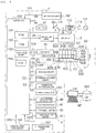
Fig. 4] Fig. 4 is a diagram illustrating an example of an electrical configuration of the infusion pump. - [
Fig. 5] Fig. 5 is a diagram illustrating a mid-press-type liquid delivering drive unit which delivers drug inside the infusion tube by squeezing and pressing the infusion tube. - [
Fig. 6] Fig. 6 is a diagram illustrating a structural example of a drive motor, and a rotational direction detection device for detecting a rotational direction of an output shaft of the drive motor. - [
Fig. 7] Fig. 7 is a diagram illustrating an example of detection information regarding the rotational direction which can be obtained from an encoder plate. - [
Fig. 8] Fig. 8 is a diagram illustrating an example of a judgment table for judging whether a magnet rotor and the output shaft of the drive motor illustrated inFig. 6(A) are in rotation in a forward rotation direction CW or in rotation in a reverse rotation direction CCW, based on the detection information regarding the rotational direction illustrated inFig. 7 . - Hereinafter, a preferable embodiment of the present invention will be described in detail with reference to the drawings.
- Since the below-described embodiment is a preferable specification example of the present invention, the embodiment is applied with various types of limitation which are technically preferable. However, the scope of the present invention is not limited to the aspects thereof unless there is disclosure particularly limiting the present invention in the following description.
-
Fig. 1 is a perspective view illustrating an infusion pump which is the preferable embodiment of the infusion pump of the present invention.Fig. 2 is a diagram of the infusion pump illustrated inFig. 1 when seen in a W-direction. - The
infusion pump 1 illustrated inFigs. 1 and2 is a continuous infusion pump which is used for a patient in infusion treatment of drug (also referred to as a drug solution) such as an anticancer drug, an anesthetic, a chemotherapeutic and the like, infusion treatment of a nutrient, a blood transfusion and the like in intensive care units (ICU, CCU, NICU) or the like, for example, at relatively high accuracy for a relatively long period of time. - The
infusion pump 1, for example, is used to select drug to be used from a drug library and to deliver the selected drug. The drug library is drug information of a dosage setting group of drug including the previously registered drug names in a drug library database (DB). A health care worker can select drug and can set the drug without performing complicated dosage setting every time by adopting the drug library. - As illustrated in
Fig. 2 , theinfusion pump 1 can accurately deliver liquid to the inside of a patient P from adrug bag 170 filled with drug (or blood) 171 through a Klemme 179, aninfusion tube 200, and an indwelling needle or an endovascularindwelling catheter 172 caused to indwell inside a vein of the patient P. Drug is also referred to as an infusion solution. An infusion tube is also referred to as an infusion line. - Otherwise, the
infusion pump 1 can accurately deliver liquid to the inside of the patient P from thebag 170 filled with anutrient 171 through the Klemme 179, theinfusion tube 200, and acatheter 172 for indwelling inside an intestinal tract. - The
infusion pump 1 has amain body cover 2 and ahandle 2T. Thehandle 2T can be stretched in an N-direction and can be accommodated in a T-direction. Themain body cover 2 is also referred to as a main body and is integrally molded with a molding resin material which is chemically resistant. Themain body cover 2 has a drip-proof treated structure which can prevent the inside of the infusion pump 1 from being penetrated by drug even if the drug or the like is splashed over the main body cover. Themain body cover 2 has such a drip-proof treated structure because there may be a case where thedrug 171 in thedrug bag 170 arranged in an upper portion is spilt, or an antiseptic solution or the like used in the vicinity thereof is splashed and adheres thereto. - Firstly, components arranged in the
main body cover 2 of theinfusion pump 1 will be described. - As illustrated in
Figs. 1 and2 , adisplay unit 3 and anoperation panel portion 4 are arranged in anupper portion 2A of themain body cover 2. Thedisplay unit 3 is an image display apparatus, and a color liquid crystal display apparatus is used, for example. Thedisplay unit 3 can display information not only by notation in Japanese but also by notation in multiple foreign languages as necessary. Thedisplay unit 3 is arranged at an upper left position in theupper portion 2A of themain body cover 2, that is, on an upper side of an opening/closing cover 5. Theupper portion 2A of themain body cover 2 is the upper half portion of themain body cover 2. Thelower portion 2B of themain body cover 2 is the lower half portion of themain body cover 2. - In the
upper portion 2A of themain body cover 2 of theinfusion pump 1, thedisplay unit 3 for displaying information and theoperation panel portion 4 including a plurality of operation buttons are arranged. Thelower portion 2B of themain body cover 2 of theinfusion pump 1 is a region in which theinfusion tube 200, that is, a delivery member for delivering drug is arranged. Accordingly, a health care worker can perform delivering of drug by using theinfusion pump 1 while confirming information on thedisplay unit 3 in theupper portion 2A of themain body cover 2. Then, the health care worker can operate the operation buttons of theoperation panel portion 4 while confirming the information on thedisplay unit 3 in theupper portion 2A of themain body cover 2. Therefore, theinfusion pump 1 has favorable operability. - In
Fig. 2 , as an example, thedisplay unit 3 displays adisplay section 3B for a planned dosage (mL) of drug, adisplay section 3C for an integrated dosage (mL) of drug, adisplay section 3D for a charge history, adisplay section 3E for a flow rate (mL/h) and the like. However, in thedisplay unit 3 illustrated inFig. 1 , the aforementioned display contents are omitted in order to simplify the drawing. Thedisplay unit 3 can additionally display a warning message. - The
operation panel portion 4 is arranged on the right side of thedisplay unit 3 in theupper portion 2A of themain body cover 2. As the operation buttons in the illustrated example, alamp 4A (formed with an LED, blinking or being lit in green during a normal operation, and blinking or being lit in red during an abnormal operation) which functions as an operational indicator, a fast-deliveringswitch button 4B, astart switch button 4C, astop switch button 4D, amenu selection button 4E, apower switch 4F and the like are arranged in theoperation panel portion 4, for example. - As illustrated in
Fig. 1 , the opening/closing cover 5 as a lid member is provided in thelower portion 2B of themain body cover 2 so as to be able to be in open and closed states in an R-direction having arotary shaft 5A as the center. The opening/closing cover 5 is a plate-like lid member formed to be elongated along the X-direction. Atube mounting portion 50 and a liquid deliveringdrive unit 60 are arranged inside the opening/closing cover 5. Theinfusion tube 200 made of a flexible thermoplastic resin, soft vinyl chloride or the like, for example, is set to thetube mounting portion 50. As the opening/closing cover 5 is in the closed state, theinfusion tube 200 can be horizontally mounted in thetube mounting portion 50 along an X-direction (the T-direction). - The X-direction, a Y-direction, and a Z-direction in
Figs. 1 and2 are orthogonal to each other. The Z-direction is a vertical direction. The X-direction is a transverse direction of theinfusion pump 1 parallel to the T-direction which is a delivering direction. The Y-direction is a front-rear direction of theinfusion pump 1. -
Fig. 3 is a perspective view illustrating thetube mounting portion 50 for mounting theinfusion tube 200 by causing the opening/closing cover 5 of theinfusion pump 1 illustrated inFigs. 1 and2 to be in an open state. - As illustrated in
Fig. 3 , thetube mounting portion 50 and the liquid deliveringdrive unit 60 are provided on a main bodylower portion 1B side of theinfusion pump 1. Thetube mounting portion 50 and the liquid deliveringdrive unit 60 are provided along the X-direction at a lower portion of thedisplay unit 3 and theoperation panel portion 4. As illustrated inFig. 2 , thetube mounting portion 50 can be covered with the opening/closing cover 5 by closing the opening/closing cover 5 in a CR-direction having therotary shaft 5A as the center. - A health care worker can mount the
infusion tube 200 in thetube mounting portion 50 and close the opening/closing cover 5 while confirming the information on thedisplay unit 3 in theupper portion 2A of themain body cover 2. Then, the health care worker can operate the operation buttons of theoperation panel portion 4 while confirming the information on thedisplay unit 3 in theupper portion 2A of themain body cover 2. Accordingly, in medical sites, operability of theinfusion pump 1 can be improved. - As illustrated in
Fig. 3 , thetube mounting portion 50 includes anair bubble sensor 51, anupstream occlusion sensor 52, adownstream occlusion sensor 53, atube clamp portion 270, a first infusiontube guide portion 54 at a position on the right side, and a second infusiontube guide portion 55 at a position on the left side. - As illustrated in
Fig. 3 , in the vicinity of thetube mounting portion 50, there is provided an infusion tube settingdirection display portion 150 for clearly displaying the T-direction as the proper delivering direction when setting theinfusion tube 200. For example, the infusion tube settingdirection display portion 150 is configured to include a plurality ofarrows 151. For example, the infusion tube settingdirection display portion 150 may be directly printed on the lower portion of thetube mounting portion 50 or may be printed on a sticker-like member so as to be pasted on the lower portion of thetube mounting portion 50. The infusion tube settingdirection display portion 150 is arranged in order to clarify the delivering direction (the T-direction) as the proper direction for thedrug 171 which is delivered through theinfusion tube 200 set inside the opening/closing cover 5. - Accordingly, it is possible to clarify the T-direction as the delivering direction of drug delivered through the
infusion tube 200 when a health care worker undoes the opening/closing cover 5 ofFig. 3 in a CS-direction, opens thetube mounting portion 50, and causes theinfusion tube 200 to be mounted in thetube mounting portion 50. Therefore, it is possible for a health care worker to be reliably prevented from erroneously mounting theinfusion tube 200 in the reverse direction. - Subsequently, a structural example of the opening/
closing cover 5 illustrated inFig. 3 will be described. - As illustrated in
Fig. 3 , the opening/closing cover 5 is a plate-like member made with a thin molding resin member in order to achieve weight reduction of theinfusion pump 1. In this manner, the weight of the opening/closing cover 5 can be reduced, and thus, the structure thereof can be simplified. The opening/closing cover 5 is supported by twohinge portions lower portion 2B of themain body cover 2 so as to be able to be in open and closed states and to cover thetube mounting portion 50 along the CS-direction and the CR-direction having therotary shaft 5A as the center. The twohinge portions first hook member 5D and a second hook member 5E. - As illustrated in
Figs. 2 and3 , an opening/closing operation lever 260 is provided on an upper right portion of the opening/closing cover 5 on an outer surface side. An infusiontube pressing member 500, thefirst hook member 5D, and the second hook member 5E are provided inside the opening/closing cover 5. The infusiontube pressing member 500 is arranged as a protruding portion having an elongated rectangular and planar shape along the X-direction. The infusiontube pressing member 500 is at a position facing the liquid deliveringdrive unit 60. The infusiontube pressing member 500 has a flat surface in the X-direction along the liquid deliveringdrive unit 60. A portion of theinfusion tube 200 is pressedly interposed between the infusiontube pressing member 500 and the liquid deliveringdrive unit 60 when the opening/closing cover 5 is in the closed state in the CR-direction. - A health care worker can set the
infusion tube 200 in the lower half portion of the main body of theinfusion pump 1 along a horizontal direction while confirming display contents displayed on thedisplay unit 3. After theinfusion tube 200 is set in thetube mounting portion 50, the opening/closing cover 5 can cover theinfusion tube 200. - As illustrated in
Fig. 3 , thefirst hook member 5D and the second hook member 5E are respectively and mechanically interlocked with fixingportions lower portion 1B side at the same time. Thus, as illustrated inFig. 2 , the opening/closing cover 5 maintains thetube mounting portion 50 at the main bodylower portion 1B in a shut-down state. Thefirst hook member 5D and the second hook member 5E including the fixingportions lower portion 1B side are configured to form a double-hook structure portion 300 of the opening/closing cover 5. - The
tube clamp portion 270 illustrated inFig. 3 clamps an intermediate portion of theinfusion tube 200 so as to be occluded by causing the opening/closing cover 5 to be in the closed state. Thetube clamp portion 270 is arranged in the vicinity of the fixingportion 1E on the left side, that is, at a position corresponding to the second hook member 5E on the left side. As a health care worker sets theinfusion tube 200 horizontally in the X-direction and the health care worker causes the opening/closing cover 5 to be in the closed state in the CR-direction, thetube clamp portion 270 can cause an intermediate portion of theinfusion tube 200 to be occluded. - As illustrated in
Fig. 3 , the first infusiontube guide portion 54 is provided at a portion on the right to the main bodylower portion 1B, and the second infusiontube guide portion 55 is provided at a portion on the left to the main bodylower portion 1B. Anupstream side 200A of theinfusion tube 200 fits the first infusiontube guide portion 54 so as to be able to be held, and adownstream side 200B of theinfusion tube 200 fits the second infusiontube guide portion 55 so as to be able to be held. Thus, theinfusion tube 200 is held in the horizontal direction along the X-direction. In this manner, theinfusion tube 200 held in the horizontal direction is fixed by being fit along theair bubble sensor 51, theupstream occlusion sensor 52, the liquid deliveringdrive unit 60, thedownstream occlusion sensor 53, and thetube clamp portion 270 in the T-direction. - As illustrated in
Fig. 3 , the second infusiontube guide portion 55 is a groove portion formed in aside surface portion 1S of the main bodylower portion 1B, thereby holding a portion of thedownstream side 200B of theinfusion tube 200 in a detachably interposed manner. Accordingly, the first infusiontube guide portion 54 and the second infusiontube guide portion 55 can be reliably mounted in thetube mounting portion 50 without nipping and squashing theinfusion tube 200 between the opening/closing cover 5 and thetube mounting portion 50. - The
air bubble sensor 51 illustrated inFig. 3 is a sensor which detects air bubbles (air) generated in theinfusion tube 200. For example, theair bubble sensor 51 is an ultrasonic sensor which monitors air bubbles included in drug flowing inside of theinfusion tube 200 from outside theinfusion tube 200 formed of soft vinyl chloride. Since transmittance of an ultrasonic wave of drug and transmittance of an ultrasonic wave of air bubbles are different from each other, an ultrasonic wave receiving unit detects the difference therebetween to monitor whether or not air bubbles are present by irradiating drug flowing inside of theinfusion tube 200 with an ultrasonic wave generated from an ultrasonic wave oscillation unit of the ultrasonic sensor. Theair bubble sensor 51 has apressing member 320 and a receivingmember 330. The ultrasonic wave oscillation unit is arranged in thepressing member 320. The ultrasonic wave receiving unit is arranged in the receivingmember 330. - The
upstream occlusion sensor 52 illustrated inFig. 3 is configured to include a Hall element and a plunger. Theupstream occlusion sensor 52 is a sensor which detects whether or not the inside of theinfusion tube 200 is occluded on theupstream side 200A of theinfusion tube 200 depending on whether or not degree (Δ) of swelling (diameter expansion) of an outer diameter of theinfusion tube 200 reaches a threshold value by detecting and outputting the swelling thereof. Thedownstream occlusion sensor 53 is configured to include the Hall element and the plunger. Thedownstream occlusion sensor 53 is a sensor which detects whether or not the inside of theinfusion tube 200 is occluded on thedownstream side 200B of theinfusion tube 200 depending on whether or not degree (Δ) of swelling (diameter expansion) of the outer diameter of theinfusion tube 200 reaches the threshold value (whether or not theinfusion tube 200 is in an occlusion state) by detecting and outputting the swelling thereof. Theupstream occlusion sensor 52 and thedownstream occlusion sensor 53 have the same configuration. As a case of occlusion in theinfusion tube 200, high viscosity of drug to be delivered, high concentration of drug and the like are exemplified. - As illustrated in
Fig. 3 , on an inner surface side of the opening/closing cover 5, pressingmembers upstream occlusion sensor 52 and thedownstream occlusion sensor 53. As a health care worker covers theinfusion tube 200 with the opening/closing cover 5 as illustrated inFig. 2 after setting theinfusion tube 200 in thetube mounting portion 50 as illustrated inFig. 3 , the pressingmember 452 and thepressing member 453 on the opening/closing cover 5 side can press portions of theinfusion tube 200 respectively against the side of the upstreamside occlusion sensor 52 and the downstreamside occlusion sensor 53. Therefore, even though aninfusion tube 200 of any size among multiple types of theinfusion tubes 200 having diameters different from one another is mounted in theinfusion pump 1, the upstreamside occlusion sensor 52 and the downstreamside occlusion sensor 53 can detect an occlusion state of theinfusion tube 200 by causing the opening/closing cover 5 to be in the closed state. - As illustrated in
Fig 4 , theinfusion pump 1 has a control unit (a computer) 100 which judges and controls the entire operation. Thecontrol unit 100 is a one-chip microcomputer, for example, and includes a read-only memory (ROM) 101, a random access memory (RAM) 102, anon-volatile memory 103, and aclock 104. In theclock 104, the current time can be corrected through a prejudged operation. In addition, the current time can be acquired, an elapsed time of prejudged delivering can be measured, and a reference time for controlling a delivering rate can be measured, for example. - A
temperature sensor 180, an opening/closing cover (opening/closing door)sensor 190, and anintravenous drip probe 197 are electrically connected to thecontrol unit 100. Thetemperature sensor 180 measures a temperature of an environment where theinfusion pump 1 is located, thereby sending a temperature measurement signal TSS. As the opening/closing cover 5 illustrated inFig. 1 is in the open state, the opening/closing cover sensor 190 sends an opening/closing cover opening/closing signal CRS to thecontrol unit 100. Theintravenous drip probe 197 is arranged in thedrug bag 170 illustrated inFig. 2 and detects a falling state of droplets of drug, thereby sending adetection signal 197 to thecontrol unit 100. - The
power switch button 4F and aswitch 111 are connected to thecontrol unit 100 illustrated inFig. 4 . Theswitch 111 performs switching between apower converter unit 112 and a rechargeable battery 113 such as a lithium-ion battery, for example, so as to supply a power source to thecontrol unit 100 from either thepower converter unit 112 or the rechargeable battery 113. Thepower converter unit 112 is connected to a commercialAC power source 115 through apower plug 114. - Returning back to
Fig. 4 , adisplay unit driver 130 drives thedisplay unit 3 in response to a command of thecontrol unit 100, thereby displaying information contents or a warning message exemplified inFig. 2 . Thespeaker 131 can notify a health care worker of various contents of warnings through audio in response to a command of thecontrol unit 100. Thebuzzer 132 can notify a health care worker of various warnings through a sound in response to a command of thecontrol unit 100. Thespeaker 131 is an example of warning means for issuing a warning to a health care worker through audio when theinfusion tube 200 is set in the N-direction which is an erroneous direction (the reverse direction). Thebuzzer 132 is another example of warning means for issuing a warning to a health care worker through a sound when theinfusion tube 200 is set in the N-direction which is an erroneous direction (the reverse direction). - In
Fig. 4 , thecontrol unit 100 is supplied with an air bubble detection signal S1 from theair bubble sensor 51, an upstream occlusion signal S2 from theupstream occlusion sensor 52 indicating that theinfusion tube 200 is occluded on the upstream side, and a downstream occlusion signal S3 from thedownstream occlusion sensor 53 indicating that theinfusion tube 200 is occluded on the downstream side. Theupstream occlusion sensor 52 and thedownstream occlusion sensor 53 can detect a state where an internal pressure of an infusion circuit exceeds a set pressure inside theinfusion pump 1 so that drug cannot be delivered. The state where an internal pressure of the infusion circuit exceeds the set pressure inside theinfusion pump 1 is caused when the infusion indwelling needle or theinfusion tube 200 is blocked, when theinfusion tube 200 is squashed or bent, when drug having high viscosity is used, and the like. - In
Fig. 4 , thecontrol unit 100 can communicate bi-directionally with acomputer 141 such as a desktop computer, for example, through acommunication port 140. Thecomputer 141 is connected to drug database (DB) 160. Drug information MF stored in thedrug database 160 can be acquired by thecontrol unit 100 through thecomputer 141 and can be stored in thenon-volatile memory 103 of thecontrol unit 100. Thecontrol unit 100 can display the drug information MF and the like on thedisplay unit 3 illustrated inFig. 2 , for example, based on the stored the drug information MF. - As the drug information MF, the name of a manufacturer of drug, the name of drug, the upper and lower limits for a planned dosage quantity (mL) of drug, the upper and lower limits for a flow rate (mL/h), contraindicated information and the like are exemplified.
- As the
drive motor 61 and anoutput shaft 61A of thedrive motor 61 in the liquid deliveringdrive unit 60 illustrated inFig. 4 rotate,eccentric cams 62A to 62F provided in acam structure body 62 which is pivotally supported by theoutput shaft 61A rotate, thereby causing a plurality offingers 63A to 63F to sequentially move back and forth in the Y-direction in as many prejudged strokes (distance between the top dead center and the bottom dead center). A step motor is used as thedrive motor 61. Thecam structure body 62 has the plurality of cams, for example, the plurality ofcams 62A to 62F. Afinger structure body 63 has the plurality offingers 63A to 63F respectively corresponding to the plurality ofcams 62A to 62F. The plurality ofcams 62A to 62F are arrayed so as to be respectively applied with phase differences. Thecam structure body 62 is interlocked with theoutput shaft 61A. - As the
output shaft 61A of thedrive motor 61 rotates in response to a command of thecontrol unit 100 illustrated inFig. 4 , the plurality offingers 63A to 63F sequentially move back and forth in the Y-direction in as many prejudged strokes. Thus, theinfusion tube 200 is pressed against the infusiontube pressing member 500 of the opening/closing cover 5 along the T-direction. Therefore, drug inside theinfusion tube 200 can be delivered in the T-direction. In other words, the plurality offingers 63A to 63F are individually driven, and the plurality offingers 63A to 63F sequentially press an outer circumferential surface of theinfusion tube 200 along the T-direction, thereby delivering drug inside theinfusion tube 200. In this manner, in accordance with a sub-control unit 400 controlling peristaltic movements of the plurality offingers 63A to 63F, thefingers 63A to 63F sequentially move back and forth as if waves ripple so as to move an occluded point of theinfusion tube 200 in the T-direction, and theinfusion tube 200 is squeezed. Thus, drug can be delivered in the T-direction. - Subsequentially, with reference to
Fig. 5 , a description will be given regarding an example in which thedrug 171 inside theinfusion tube 200 is delivered by causing thefinger structure body 63 of the liquid deliveringdrive unit 60 to press theinfusion tube 200. -
Figs. 5(A) to 5(F) illustrate a so-called mid-press-type liquid deliveringdrive unit 60 which delivers thedrug 171 by squeezing theinfusion tube 200 in the T-direction so as to press the inside of theinfusion tube 200. In other words, the liquid deliveringdrive unit 60 causes thefingers infusion tube 200, excluding thefingers infusion tube 200, thereby delivering thedrug 171 inside theinfusion tube 200. In this manner, theinfusion tube 200 is not completely squashed by thefinger structure body 63 of the mid-press-type liquid deliveringdrive unit 60. Therefore, it is possible to accurately deliver an amount of thenecessary drug 171 to be delivered, by squashing a certain quantity of theinfusion tube 200 within a range causing less deformation and fatigue in theinfusion tube 200. - In
Fig. 5(A) , theinfusion tube 200 is completely and closely pressed by thefinger 63B, and thedrug 171 flows into theinfusion tube 200 in the T-direction. InFig. 5(B) , thedrug 171 stops flowing, and theinfusion tube 200 is shut down by thefinger 63F. Thus, a certain amount of thedrug 171 can be secured between thefingers infusion tube 200. - In
Fig. 5(C) , thefinger 63B is released from completely pressing theinfusion tube 200, and thefinger 63E presses partway theinfusion tube 200. Moreover, inFig. 5(D) , thefingers infusion tube 200, thereby discharging thedrug 171 in the T-direction. - In
Fig. 5(E) , thefinger 63B presses theinfusion tube 200 again, and thedrug 171 stops to be discharged in the T-direction (the same state as the state inFig. 5(A) ). Thereafter, the procedure returns to the initial state inFig. 5(A) . Thedrug 171 can be delivered in the T-direction by repeating the procedure of pressing theinfusion tube 200 described above. - Subsequently, with reference to
Fig. 6 , a description will be given regarding a structural example of thedrive motor 61, and a rotationaldirection detection device 700 for detecting a rotational direction of anoutput shaft 161C of thedrive motor 61.Fig. 6 illustrates the structural example of thedrive motor 61, and the rotationaldirection detection device 700 for detecting the rotational direction of theoutput shaft 161C of thedrive motor 61.Fig. 7 illustrates an example ofdetection information 780 regarding the rotational direction obtained from anencoder plate 701. -
Fig. 6(A) illustrates thedrive motor 61, the rotationaldirection detection device 700 for detecting the rotational direction of theoutput shaft 161C of thedrive motor 61, and the liquid deliveringdrive unit 60.Fig. 6(B) illustrates the structural example of thedrive motor 61, and the rotationaldirection detection device 700 for detecting the rotational direction of theoutput shaft 161C of thedrive motor 61. - As illustrated in
Fig. 6(A) , thecontrol unit 100 is electrically connected to thedrive motor 61 through amotor driver 134. As thecontrol unit 100 issues a command CT to themotor driver 134, themotor driver 134 can cause thedrive motor 134 to rotate forward. A step motor (a stepping motor) is preferably used as thedrive motor 61. As exemplified inFig. 6(B) , thedrive motor 61 is a 2-phase 4-pole-type step motor or the like, for example. However, the step motor may be structured to be a three-phase step motor, for example. - As illustrated in
Fig. 6(B) , in a case of the 2-phase 4-pole-type step motor, thedrive motor 61 has a magnet rotor 161A and anelectromagnet stator 161B. The magnet rotor 161A is a permanent magnet having the N-pole and the S-pole and is rotatable in thestator 161B. The magnet rotor 161A is fixed to theoutput shaft 161C illustrated inFig. 6 . Thestator 161B has four excitation coils which are arranged every 90 degrees in the clockwise direction, for example. In the four excitation magnet coils, acoil 181A is an X-terminal, acoil 181B is a Y-terminal, a coil 181C is an X-bar terminal, and acoil 181D is a Y-bar terminal. - The
magnet rotor 61A is set to rotate in the forward rotation direction CW when a 2-phase excitation pulse-like input current waveform SCW for forward rotation illustrated in Fig. 10(A) is applied to thecoils Fig. 6(B) from themotor driver 134 in order, in response to the command CT of thecontrol unit 100 illustrated inFig. 4 . In this manner, an angle of the magnet rotor 161A in the rotational direction can be accurately controlled by employing the step motor as thedrive motor 61. In a stationary state, since the magnet rotor 161A is fixed due to magnetism, a force of the magnet rotor 161A to be stationary is great, thereby being suitable for stopping at a certain angle. - As illustrated in
Fig. 6(A) and 6(B) , the rotationaldirection detection device 700 is configured to have theencoder plate 701 and anoptical coupler 749. The disk-type encoder plate 701 is fixed to theoutput shaft 161C. Theencoder plate 701 includes a lighttransmitting pattern portion 702 which has a preset shape and allows light to pass therethrough, and a lightblocking pattern portion 703 which allows no light to pass therethrough. The lightblocking pattern portion 703 has a 1X-speed region 703A which is at a position on an outer circumferential side about a central axis CLT, and a 3X-speed region 703B which is at a position on an inner circumferential side about the central axis CLT corresponding to a 3X speed. The 1X-speed region 703A is a fan-shaped portion of which the circumferential speed corresponds to a 1X speed when theencoder plate 701 rotates in the forward rotation direction CW having the central axis CL as the center. In contrast, the 3X-speed region 703B is a fan-shaped portion of which the circumferential speed corresponds to a 3X speed when theencoder plate 701 rotates in the forward rotation direction CW having the central axis CL as the center. - As illustrated in
Fig. 6(A) , theoutput shaft 161C and theoutput shaft 61A are individually formed in theactual drive motor 61. The encoder plate 710 is fixed onto theoutput shaft 161C side, and theoutput shaft 61A is interlocked to thecam structure body 62 of the liquid deliveringdrive unit 60. An outer circumferential surface of theencoder plate 701 is interlocked to theoutput shaft 61A on thecam structure body 62 side by using abelt 699. - As illustrated in
Figs. 6(A) and 6(B) , theoptical coupler 749 is arranged in the vicinity of theencoder plate 701. Theoptical coupler 749 has alight emitting unit 751 and alight receiving unit 752. Thelight emitting unit 751 is arranged on one surface side of theencoder plate 701 and has two light emittingdiodes light receiving unit 752 is arranged on the other surface side of theencoder plate 701 and has twolight receiving diodes control unit 100 causes thelight emitting diodes light emitting unit 751 to emit light, thelight receiving diodes light receiving unit 752 respectively at the corresponding positions can receive light. - As the
motor driver 134 applies the 2-phase excitation pulse-like input current waveform SCW for forward rotation to thedrive motor 61 in response to the command CT of thecontrol unit 100 illustrated inFig. 6(A) , the magnet rotor 161A and theoutput shaft 161C of thedrive motor 61 continuously rotate in the forward rotation direction CW. Accordingly, since theencoder plate 701 rotates in the forward rotation direction CW, light emitted from thelight emitting diodes transmitting pattern portion 702 and is blocked by the lightblocking pattern portion 703. In this example, if light of thelight emitting diodes blocking pattern portion 703, thelight receiving diodes control unit 100. If light of thelight emitting diodes pattern portion 702, thelight receiving diodes control unit 100. - Accordingly, as illustrated in
Fig. 7 , thecontrol unit 100 illustrated inFig. 6(A) obtains information of the rotational speed together with thedetection information 780 from theencoder plate 701 regarding the rotational direction (whether the forward rotation or the reverse rotation). Thedetection information 780 regarding the rotational direction indicates positional information which relates to the rotational direction of theencoder plate 701, that is, positional information of the magnet rotor 161A of thedrive motor 61.Fig. 7 exemplifies thedetection information 780 regarding the rotational direction, and thedetection information 780 regarding the rotational direction includes a 1X-speedoutput waveform signal 781 illustrated inFig. 7 (A) , and a 3X-speedoutput waveform signal 782 illustrated inFig. 7(B) . The 1X-speedoutput waveform signal 781 is the first output waveform signal, and the 3X-speedoutput waveform signal 782 is the second output waveform signal. The 3X-speedoutput waveform signal 782 is a fast-forward signal compared to the 1X-speedoutput waveform signal 781. Additionally,Fig. 7 illustrates an origin point OR of rotation, and a position (0), a position (1), a position (2), and a position (3) of the rotational direction. Here, a falling position of the 3X-speedoutput waveform signal 782 is set as the origin point OR of rotation. - Each pulse cycle of the 1X-speed
output waveform signal 781 and each pulse cycle of the 3X-speedoutput waveform signal 782 which is illustrated inFig. 7(B) correspond to the rotational speed of the magnet rotor 161A of thedrive motor 61. The rotational speed of the magnet rotor 161A of thedrive motor 61 corresponds to an operational speed of each finger of thefinger structure body 63. The operational speed of the fingers is substantially proportional to a flow rate of drug inside theinfusion tube 200. Accordingly, thecontrol unit 100 can control the flow rate of drug on account of each pulse cycle (a pulse rate) of the 1X-speedoutput waveform signal 781 and each pulse cycle (a pulse rate) of the 3X-speedoutput waveform signal 782 which is illustrated inFig. 7(B) . Since the pulse rate increases if a pulse width is narrowed, and the pulse rate decreases if the pulse width is widened, thecontrol unit 100 controls the pulse rate, that is, the flow rate of drug by adjusting the pulse width. -
Fig. 8 illustrates a judgment table 798 indicating judgment examples of the magnet rotor 161A and theoutput shaft 161C of thedrive motor 61 ofFig. 6(A) in the forward rotation direction CW or the reverse rotation direction CCW based on thedetection information 780 regarding the rotational direction illustrated inFig. 7 . In respect to thedetection information 780 regarding the rotational direction illustrated inFig. 7 , thecontrol unit 100 inFig. 6(A) compares current encoder information IF1 and immediately preceding (immediate past) encoder information IF0 immediately preceding the current encoder information IF1 which are indicated in the judgment table 798 ofFig. 8 , thereby being able not only to judge whether the magnet rotor 161A and theoutput shaft 161C rotate in the forward rotation direction CW, rotate in the reverse rotation direction CCW, or in a state other than thereof but also to judge whether or not the rotational speed is normal as well based on the information of the rotational speed. - The judgment table 798 illustrated in
Fig. 8 indicates judgment criteria for thecontrol unit 100. The judgment table 798 is previously stored in theROM 101 illustrated inFig. 4 , for example. - With reference to
Fig. 8 , the examples of the judgment contents of the judgment table 798 will be sequentially described. The judgment table 798 inFig. 8 indicates the current encoder information IF1 and the immediately preceding encoder information IF0. - In the judgment table 798 of
Fig. 8 , "L : L" denotes a case where "the 1X-speedoutput waveform signal 781 is at Low level : the 3X-speedoutput waveform signal 782 is at Low level". - "L : H" denotes a case where "the 1X-speed
output waveform signal 781 is at the Low level : the 3X-speedoutput waveform signal 782 is at High level". - "H : L" denotes a case where "the 1X-speed
output waveform signal 781 is at the High level : the 3X-speedoutput waveform signal 782 is at the Low level". Then, "H : H" denotes a case where "the 1X-speedoutput waveform signal 781 is at the High level : the 3X-speedoutput waveform signal 782 is at the High level". - Moreover, the judgment table 798 in
Fig. 8 indicates item sections (1-1) to (1-4) in the lateral direction and indicates item sections (2-1) to (2-4) in the vertical direction. - Subsequently, an operational example of the
infusion pump 1 will be described. - When a health care worker presses the
power switch 4F illustrated inFig. 4 so as to causeinfusion pump 1 to be switched on, thecontrol unit 100 illustrated inFig. 6(A) issues the command CT to themotor driver 134, thereby operating thedrive motor 61. When thedrive motor 61 operates, theoutput shaft 61A of thecam structure body 62 continuously rotates in the forward rotation direction CW via thebelt 699 in accordance with the continuous rotations of theoutput shaft 161C and theencoder plate 701 of thedrive motor 61 in the forward rotation direction CW, illustrated inFig. 6(A) . Accordingly, thecam structure body 62 presses each finger of thefinger structure body 63, and thus, each finger sequentially presses the outer circumferential surface of theinfusion tube 200 along the T-direction, thereby delivering drug inside theinfusion tube 200. - In this manner, as the
output shaft 161C and theencoder plate 701 of thedrive motor 61 continuously rotates in the forward rotation direction CW, thecontrol unit 100 obtains thedetection information 780 regarding the rotational direction from theencoder plate 701. Thedetection information 780 regarding the rotational direction is the positional information of theencoder plate 701, that is, the positional information of the magnet rotor 161A of thedrive motor 61. Thedetection information 780 regarding the rotational direction illustrated inFig. 7 is characterized by including the 1X-speedoutput waveform signal 781 and the 3X-speedoutput waveform signal 782. - Meanwhile, since an occlusion pressure is mitigated when the
control unit 100 receives a downstream occlusion signal S3 from thedownstream occlusion sensor 53 indicating that a downstream side of theinfusion tube 200 is in an occlusion state from thedownstream occlusion sensor 53, thedrive motor 61 is caused to stop continuously rotating in the forward rotation direction CW. Thereafter, thedrive motor 61 is caused to reversely rotate while judging whether or not thedrive motor 61 is driven in the reverse rotation. - A plurality of prejudged conditions for stopping the reverse rotation are set as described in the following 1) to 4), for example. However, the conditions are examples, and the embodiment is not limited thereto.
- 1) An output by the Hall element drops to the extent of 80% with respect to a value corresponding to an occlusion state.
- 2) "The quantity of reverse rotation" has a prejudged number of steps.
- 3) The integrated dosage becomes less than the integrated dosage when liquid starts to be delivered.
- 4) The integrated dosage becomes zero.
- The
control unit 100 illustrated inFig. 6 can judge a positional change, that is, whether the magnet rotor 161A and theoutput shaft 161C of thedrive motor 61, and theoutput shaft 61A of thecam structure body 62 illustrated inFig. 6 (A) are in the forward rotation state or the reverse rotation state, according to the judgment table 798 illustrated inFig. 8 . - With reference to
Figs. 6(A) ,7, and 8 , the judgment examples of the positional change of the magnet rotor 161A and theoutput shaft 161C of thedrive motor 61 will be described. - In the judgment table 798 of
Fig. 8 , since the current encoder information IF1 is "L : L" in the item section (1-1), and the immediately preceding encoder information IFO is "L : L" in the item section (2-1), with reference toFig. 7 , thecontrol unit 100 judges that there is "no positional change" of the magnet rotor 161A of thedrive motor 61. - In the judgment table 798 of
Fig. 8 , since the current encoder information IF1 is "L : H" in the item section (1-2), and the immediately preceding encoder information IFO is "L : L" in the item section (2-1), with reference toFig. 7 , thecontrol unit 100 judges that the magnet rotor 161A of thedrive motor 61 is in "the forward rotation: the position (2)". - In the judgment table 798 of
Fig. 8 , since the current encoder information IF1 is "H : L" in the item section (1-3), and the immediately preceding encoder information IFO is "L : L" in the item section (2-1), with reference toFig. 7 , thecontrol unit 100 judges that the magnet rotor 161A of thedrive motor 61 is at "the position OB in the forward rotation: the positions OA and OC in the reverse rotation". - In the judgment table 798 of
Fig. 8 , since the current encoder information IF1 is "H : H" in the item section (1-4), and the immediately preceding encoder information IF0 is "L : L" in the item section (2-1), with reference toFig. 7 , thecontrol unit 100 judges that the magnet rotor 161A of thedrive motor 61 is in "the rotation state: the position is unidentified". - Subsequently, in the judgment table 798 of
Fig. 8 , since the current encoder information IF1 is "L : L" in the item section (1-1), and the immediately preceding encoder information IF0 is "L : H" in the item section (2-2), with reference toFig. 7 , thecontrol unit 100 judges that the magnet rotor 161A of thedrive motor 61 is in "the reverse state (the reverse rotation) : the position (2)". - In the judgment table 798 of
Fig. 8 , since the current encoder information IF1 is "L : H" in the item section (1-2), and the immediately preceding encoder information IFO is "L : H" in the item section (2-2), with reference toFig. 7 , thecontrol unit 100 judges that there is "no positional change" of the magnet rotor 161A of thedrive motor 61. - In the judgment table 798 of
Fig. 8 , since the current encoder information IF1 is "H : L" in the item section (1-3), and the immediately preceding encoder information IFO is "L : H" in the item section (2-2), with reference toFig. 7 , thecontrol unit 100 judges that the magnet rotor 161A of thedrive motor 61 is in "the rotation: the position is unidentified". - In the judgment table 798 of
Fig. 8 , since the current encoder information IF1 is "H : H" in the item section (1-4), and the immediately preceding encoder information IF0 is "L : H" in the item section (2-2), with reference toFig. 7 , thecontrol unit 100 judges that the magnet rotor 161A of thedrive motor 61 is in "the forward rotation: the position (3)". - Subsequently, in the judgment table 798 of
Fig. 8 , since the current encoder information IF1 is "L : L" in the item section (1-1), and the immediately preceding encoder information IF0 is "H : L" in the item section (2-3), with reference toFig. 7 , thecontrol unit 100 judges that the magnet rotor 161A of thedrive motor 61 is at "the positions OA and OC in the forward rotation: the position OB in the reverse rotation". - In the judgment table 798 of
Fig. 8 , since the current encoder information IF1 is "L : H" in the item section (1-2), and the immediately preceding encoder information IF0 is "H : L" in the item section (2-3), with reference toFig. 7 , thecontrol unit 100 judges that the magnet rotor 161A of thedrive motor 61 is in "the rotation: the position is unidentified". - In the judgment table 798 of
Fig. 8 , since the current encoder information IF1 is "H: L" in the item section (1-3), and the immediately preceding encoder information IF0 is "H : L" in the item section (2-3), with reference toFig. 7 , thecontrol unit 100 judges that there is "no positional change" of the magnet rotor 161A of thedrive motor 61. - In the judgment table 798 of
Fig. 8 , since the current encoder information IF1 is "H: H" in the item section (1-4), and the immediately preceding encoder information IF0 is "H : L" in the item section (2-3), with reference toFig. 7 , thecontrol unit 100 judges that the magnet rotor 161A of thedrive motor 61 is in "the reverse state (the reverse rotation) : the position (1)". - In the judgment table 798 of
Fig. 8 , since the current encoder information IF1 is "L : L" in the item section (1-1), and the immediately preceding encoder information IF0 is "H : H" in the item section (2-4), with reference toFig. 7 , thecontrol unit 100 judges that the magnet rotor 161A of thedrive motor 61 is in "the rotation: the position is unidentified". - In the judgment table 798 of
Fig. 8 , since the current encoder information IF1 is "L : H" in the item section (1-2), and the immediately preceding encoder information IF0 is "H : H" in the item section (2-4), with reference toFig. 7 , thecontrol unit 100 judges that the magnet rotor 161A of thedrive motor 61 is in "the reverse state (the reverse rotation) : the position (3)". - In the judgment table 798 of
Fig. 8 , since the current encoder information IF1 is "H : L" in the item section (1-3), and the immediately preceding encoder information IF0 is "H : H" in the item section (2-4), with reference toFig. 7 , thecontrol unit 100 judges that the magnet rotor 161A of thedrive motor 61 is in "the forward rotation: the position (1)". - In the judgment table 798 of
Fig. 8 , since the current encoder information IF1 is "H : H" in the item section (1-4), and the immediately preceding encoder information IF0 is "H : H" in the item section (2-4), with reference toFig. 7 , thecontrol unit 100 judges that there is "no positional change" of the magnet rotor 161A of thedrive motor 61. - As described above, the
control unit 100 inFig. 6(A) can judge whether the magnet rotor 161A and theoutput shaft 161C of thedrive motor 61, and theoutput shaft 61A of thecam structure body 62 are in the forward rotation state at the faster rotational speed, that is, the 3X-speed (the speed faster than the 1X-speed), in the reverse rotation state, or in a state other than thereof based on the combination of the current encoder information IF1 and the immediately preceding encoder information IF0 illustrated inFig. 8 , by obtaining the 1X-speed output waveform signal 718 and the 3X-speedoutput waveform signal 782 illustrated inFig. 7 . As thecontrol unit 100 judges the positional change, the forward rotation and the reverse rotation of the rotor of the drive motor can be detected. Thus, it is possible to safely deliver drug to a patient. In order to prevent the downstream side from being temporarily (instantaneously) stopped in delivering drug, the magnet rotor 161A and theoutput shaft 161C of thedrive motor 61, and theoutput shaft 61A of thecam structure body 62 are controlled to be at the 3X speed during a period until the state reaches that illustrated inFig. 5(B) via the states illustrated inFigs. 5(E) to 5(A) . - However, in accordance with the number and shape of the fingers, without being limited to the 3X speed, it is possible to appropriately set to a 2X speed or faster.
- In a case of a so-called full-press-type infusion pump in which all of the fingers completely and closely press the
infusion tube 200 in order, the speed is controlled to be faster than the 1X speed while the finger on the farthest downstream side (corresponding to thefinger 63A) completely releases theinfusion tube 200 from the closely pressed state and the finger on the farthest upstream side (corresponding to thefinger 63F) completely and closely presses theinfusion tube 200. - As necessary, when the magnet rotor 161A and the
output shaft 161C of thedrive motor 61, and theoutput shaft 61A of thecam structure body 62 are in the reverse rotation instead of the forward rotation, thecontrol unit 100 can display "the drive motor is in the reverse rotation" on thedisplay unit 3, can notify a health care worker of "the reverse rotation of the drive motor" through audio by using thespeaker 131 illustrated inFig. 4 , or can issue an alarm through a sound by using thebuzzer 132. - For example, when the magnet rotor 161A and the
output shaft 161C of thedrive motor 61, and theoutput shaft 61A of thecam structure body 62 are in the reverse rotation, thecontrol unit 100 can promptly stop the operation of thedrive motor 61. - The
infusion pump 1 according to the embodiment of the present invention includes the drive motor, the liquid delivering drive unit that delivers drug inside the infusion tube by pressing the infusion tube on account of the rotor of the drive motor in forward rotation, the rotational direction detection device that generates detection information regarding a rotational direction for judging whether the rotor of the drive motor is in the forward rotation or the reverse rotation, and the control unit that judges whether the rotor of the drive motor is in the forward rotation or the reverse rotation based on the detection information regarding the rotational direction obtained from the rotational direction detection device. Accordingly, the control unit can judge whether the rotor of the drive motor is in the forward rotation or the reverse rotation based on the detection information regarding the rotational direction obtained from the rotational direction detection device. Therefore, it is possible to detect the forward rotation and the reverse rotation of the rotor of the drive motor so as to be able to safely deliver drug to a patient. - The rotational direction detection device includes the encoder plate which is fixed to the rotor of the drive motor, and the optical coupler which obtains the first output waveform signal and the second output waveform signal different from the first output waveform signal by irradiating the encoder plate with light so as to send the first output waveform signal and the second output waveform signal to the control unit as the detection information regarding the rotational direction. Accordingly, it is simply performed that the optical coupler optically generates the first output waveform signal and the second output waveform signal so as to send to the control unit as the detection information regarding the rotational direction of the rotor. And thus, it is possible to simplify the structure thereof.
- The first output waveform signal is the output waveform signal at 1X speed, and the second output waveform signal is the output waveform signal at 3X speed. The control unit judges whether the rotor is in the forward rotation or the reverse rotation by comparing the first output waveform signal and the second output waveform signal. Accordingly, since the control unit has only to compare the first output waveform signal and the second output waveform signal, it is possible to accurately judge whether the rotor is in the forward rotation or the reverse rotation.
- The liquid delivering drive unit includes the plurality of cams which rotate on account of the forward rotation of the drive motor, and the plurality of fingers which deliver the drug inside the infusion tube while sequentially pressing the infusion tube in the longitudinal direction on account of the plurality of cams in rotation. Accordingly, the plurality of fingers can reliably deliver drug inside the infusion tube to a patient side by causing the plurality of cams to rotate forward.
- The display unit displaying information and the operation panel portion having the operation buttons are arranged in the upper portion of the main body of the infusion pump, and the infusion tube is arranged in a region of the lower portion of the main body of the infusion pump. Accordingly, a health care worker can perform delivering of drug by using the infusion pump while confirming the information on the display unit in the upper portion of the main body. Then, the health care worker can operate the operation button of the operation panel portion while confirming the information on the display unit in the upper portion of the main body.
- The present invention is not limited to the above-described embodiment, and thus, various changes and modifications can be made without departing from the scope of the Claims.
- In
Fig. 5 , as the liquid deliveringdrive unit 60, the embodiment of the infusion pump of the present invention exemplifies a mid-press-type liquid delivering drive unit which delivers thedrug 171 inside theinfusion tube 200 by pressing theinfusion tube 200 without completely squashing. However, without being limited thereto, as the liquid deliveringdrive unit 60, a full-press-type liquid delivering drive unit may be employed which delivers thedrug 171 inside theinfusion tube 200 by completely squashing theinfusion tube 200. - Each configuration in the above-described embodiment can be partially omitted and can be arbitrarily combined so as to be different from above.
-
- 1 ... infusion pump,
- 3 ... display unit,
- 50 ... tube mounting portion,
- 60 ... liquid delivering drive unit,
- 61 ... drive motor,
- 100 ... control unit,
- 101 ... ROM,
- 161A ... magnet roller (rotor),
- 171 ... drug,
- 200 ... infusion tube,
- 700 ... rotational direction detection device,
- 749 ... optical coupler,
- 780 ... detection information regarding rotational direction,
- 781 ... output waveform signal at 1X speed (first output waveform signal),
- 782 ... output waveform signal at 3X speed (second output waveform signal), and
- 798 ... judgment table
Claims (5)
- An infusion pump for delivering a drug to a patient by causing a distal opening portion of an endovascular indwelling catheter or an indwelling needle, which communicates with an infusion tube, to indwell inside a vein or an intestinal tract of the patient,
the infusion pump comprising:a drive motor;a liquid delivering drive unit that delivers the drug inside the infusion tube by pressing the infusion tube on account of a rotor of the drive motor in forward rotation;a rotational direction detection device that generates detection information regarding a rotational direction for judging whether the rotor of the drive motor is in the forward rotation or reverse rotation;a downstream occlusion sensor that detects whether the infusion tube is occluded; anda control unit,wherein the control unit judges whether the rotor of the drive motor is in the forward rotation or the reverse rotation based on the detection information regarding the rotational direction obtained from the rotational direction detection device,wherein the control unit also judges whether a rotational speed of the rotor is normal, wherein, while causing the rotational direction detection device to detect that the rotor of the drive motor is in the forward rotation and if an occlusion state is detected by the downstream occlusion sensor when delivering liquid in the forward rotation, the control unit stops the forward rotation, and wherein, while causing the rotational direction detection device to detect that the rotor of the drive motor is in the reverse rotation, the control unit controls the drive motor so as to be driven in the reverse rotation until fulfilling a prejudged condition. - The infusion pump according to claim 1, wherein the rotational direction detection device includes an encoder plate, having an inner circumferential region of a light-blocking pattern and an outer circumferential region of a light-blocking pattern, which is fixed to the rotor of the drive motor, and an optical coupler which obtains a first output waveform signal and a second output waveform signal different from the first output waveform signal by irradiating the encoder plate with light so as to send one of the first output waveform signal and the second output waveform signal to the control unit as the detection information regarding the rotational direction.
- The infusion pump according to claim 2, wherein the first output waveform signal is an output waveform signal from the inner circumferential region of a light blocking pattern portion, and the second output waveform signal is an output waveform signal from the outer circumferential region of a light blocking pattern portion, and
the control unit judges whether the rotor is in the forward rotation or the reverse rotation by comparing the first output waveform signal and the second output waveform signal. - The infusion pump according to claim 1, wherein the liquid delivering drive unit includes a plurality of cams which rotate on account of the forward rotation of the drive motor, and a plurality of fingers which deliver the drug inside the infusion tube while sequentially pressing the infusion tube in a longitudinal direction on account of the plurality of cams in rotation.
- The infusion pump according any one of claims 1 to 4, wherein a display unit displaying information and an operation panel portion having an operation button are arranged in an upper portion of a main body of the infusion pump, and the infusion tube is arranged in a region of a lower portion of the main body of the infusion pump.
Priority Applications (1)
| Application Number | Priority Date | Filing Date | Title |
|---|---|---|---|
| EP17207218.3A EP3323447B1 (en) | 2012-09-27 | 2012-09-27 | Infusion pump |
Applications Claiming Priority (3)
| Application Number | Priority Date | Filing Date | Title |
|---|---|---|---|
| EP12885538.4A EP2902047B1 (en) | 2012-09-27 | 2012-09-27 | Infusion pump |
| EP17207218.3A EP3323447B1 (en) | 2012-09-27 | 2012-09-27 | Infusion pump |
| PCT/JP2012/006217 WO2014049661A1 (en) | 2012-09-27 | 2012-09-27 | Infusion pump |
Related Parent Applications (2)
| Application Number | Title | Priority Date | Filing Date |
|---|---|---|---|
| EP12885538.4A Division EP2902047B1 (en) | 2012-09-27 | 2012-09-27 | Infusion pump |
| EP12885538.4A Division-Into EP2902047B1 (en) | 2012-09-27 | 2012-09-27 | Infusion pump |
Publications (2)
| Publication Number | Publication Date |
|---|---|
| EP3323447A1 true EP3323447A1 (en) | 2018-05-23 |
| EP3323447B1 EP3323447B1 (en) | 2021-06-09 |
Family
ID=50387130
Family Applications (2)
| Application Number | Title | Priority Date | Filing Date |
|---|---|---|---|
| EP17207218.3A Active EP3323447B1 (en) | 2012-09-27 | 2012-09-27 | Infusion pump |
| EP12885538.4A Active EP2902047B1 (en) | 2012-09-27 | 2012-09-27 | Infusion pump |
Family Applications After (1)
| Application Number | Title | Priority Date | Filing Date |
|---|---|---|---|
| EP12885538.4A Active EP2902047B1 (en) | 2012-09-27 | 2012-09-27 | Infusion pump |
Country Status (5)
| Country | Link |
|---|---|
| US (1) | US10549033B2 (en) |
| EP (2) | EP3323447B1 (en) |
| JP (1) | JP6433294B2 (en) |
| CN (1) | CN104582752B (en) |
| WO (1) | WO2014049661A1 (en) |
Cited By (1)
| Publication number | Priority date | Publication date | Assignee | Title |
|---|---|---|---|---|
| CN110662566A (en) * | 2017-03-22 | 2020-01-07 | 爱康思宝实验室株式会社 | Infusion pump |
Families Citing this family (51)
| Publication number | Priority date | Publication date | Assignee | Title |
|---|---|---|---|---|
| PT1762259E (en) | 2005-09-12 | 2010-12-10 | Unomedical As | INSERTER FOR AN INFUSION ASSEMBLY WITH A FIRST AND SECOND SPRING UNITS |
| JP2013523233A (en) | 2010-03-30 | 2013-06-17 | ウノメディカル アクティーゼルスカブ | Medical device |
| US10194938B2 (en) | 2011-03-14 | 2019-02-05 | UnoMedical, AS | Inserter system with transport protection |
| EP2763723B1 (en) | 2011-10-05 | 2016-04-13 | Unomedical A/S | Inserter for simultaneous insertion of multiple transcutaneous parts |
| EP2583715A1 (en) | 2011-10-19 | 2013-04-24 | Unomedical A/S | Infusion tube system and method for manufacture |
| USD736370S1 (en) | 2013-06-11 | 2015-08-11 | Deka Products Limited Partnership | Medical pump |
| USD767756S1 (en) | 2013-06-11 | 2016-09-27 | Deka Products Limited Partnership | Medical pump |
| USD735319S1 (en) | 2013-06-11 | 2015-07-28 | Deka Products Limited Partnership | Medical pump |
| USD760782S1 (en) | 2013-12-20 | 2016-07-05 | Deka Products Limited Partnership | Display screen of a medical pump with a graphical user interface |
| KR101984116B1 (en) | 2015-01-12 | 2019-05-31 | 켄달리온 테라퓨틱스 인코포레이티드 | Micro-droplet delivery device and method |
| JP6714007B2 (en) * | 2015-02-02 | 2020-06-24 | サノフィ−アベンティス・ドイチュラント・ゲゼルシャフト・ミット・ベシュレンクテル・ハフツング | How to prime a medical pump |
| USD803386S1 (en) * | 2015-02-10 | 2017-11-21 | Deka Products Limited Partnership | Syringe medical pump |
| USD803387S1 (en) * | 2015-02-10 | 2017-11-21 | Deka Products Limited Partnership | Syringe medical pump |
| USD801519S1 (en) * | 2015-02-10 | 2017-10-31 | Deka Products Limited Partnership | Peristaltic medical pump |
| USD805183S1 (en) * | 2015-02-10 | 2017-12-12 | Deka Products Limited Partnership | Medical pump |
| CN104815367B (en) * | 2015-05-14 | 2017-09-12 | 深圳市科曼医疗设备有限公司 | Transfusion device internal congestion pressure method for releasing, device and infusion pump |
| USD894373S1 (en) * | 2015-09-30 | 2020-08-25 | Fresenius Vial Sas | Syringe pump |
| JP6914848B2 (en) * | 2015-11-20 | 2021-08-04 | テルモ株式会社 | Medical pump and its control method |
| EP4740989A2 (en) | 2016-01-19 | 2026-05-13 | Unomedical A/S | Cannula & infusion devices |
| EP3228343A1 (en) * | 2016-04-06 | 2017-10-11 | Fresenius Vial SAS | Method for operating an infusion device |
| CN205544743U (en) * | 2016-04-19 | 2016-08-31 | 合肥新沪屏蔽泵有限公司 | Pump assembly |
| WO2018061562A1 (en) | 2016-09-27 | 2018-04-05 | テルモ株式会社 | Liquid medicine administration device |
| CA3039106A1 (en) | 2017-01-20 | 2018-07-26 | Kedalion Therapeutics, Inc. | Piezoelectric fluid dispenser |
| USD909567S1 (en) * | 2017-09-20 | 2021-02-02 | Fresenius Vial Sas | Medical infusion pump |
| CN107823756B (en) * | 2017-10-12 | 2021-03-12 | 英华达(上海)科技有限公司 | Infusion device |
| JP7436363B2 (en) | 2017-12-08 | 2024-02-21 | ノバルティス アーゲー | fluid delivery alignment system |
| CN107941517A (en) * | 2017-12-30 | 2018-04-20 | 长沙迪普美医疗科技有限公司 | Infusion pump drives detection device and method |
| US12011567B2 (en) | 2018-02-11 | 2024-06-18 | Eitan Medical Ltd. | Flex-stroke infusion pump |
| US12350194B1 (en) | 2018-04-12 | 2025-07-08 | Bausch + Lomb Ireland Limited | Topical ocular delivery of fluids with controlled mass dosing and wireless communication |
| US20190314197A1 (en) | 2018-04-12 | 2019-10-17 | Kedalion Therapeutics, Inc. | Topical Ocular Delivery Methods and Devices for Use in the Same |
| JP6981448B2 (en) * | 2018-06-08 | 2021-12-15 | オムロン株式会社 | Controllers, controller control methods, learning devices, and programs |
| CA3102410A1 (en) | 2018-07-03 | 2020-01-09 | Kedalion Therapeutics, Inc. | Topical ocular delivery devices and methods for using the same |
| EP3705148B1 (en) | 2019-03-04 | 2024-06-19 | Eitan Medical Ltd. | In cycle pressure measurement |
| EP3934716B1 (en) | 2019-03-05 | 2025-05-07 | Eitan Medical Ltd | Anti-free-flow valve |
| US12214162B2 (en) | 2019-03-05 | 2025-02-04 | Eitan Medical Ltd. | Infusion pump with valve compensation |
| US12318576B2 (en) | 2019-03-05 | 2025-06-03 | Eitan Medical Ltd. | Infusion pump with toggling capability |
| WO2020178825A1 (en) | 2019-03-05 | 2020-09-10 | Avoset Health Ltd. | Infusion pump cassette latch |
| US11679028B2 (en) | 2019-03-06 | 2023-06-20 | Novartis Ag | Multi-dose ocular fluid delivery system |
| US12097145B2 (en) | 2019-03-06 | 2024-09-24 | Bausch + Lomb Ireland Limited | Vented multi-dose ocular fluid delivery system |
| WO2020202852A1 (en) * | 2019-03-29 | 2020-10-08 | テルモ株式会社 | Liquid medicine administration apparatus |
| CA3141608A1 (en) | 2019-05-20 | 2020-11-26 | Unomedical A/S | Rotatable infusion device and methods thereof |
| JP7767271B2 (en) * | 2019-08-28 | 2025-11-11 | スミスズ メディカル エーエスディー,インコーポレイティド | Post-occlusion bolus reduction system and method |
| US12496218B1 (en) | 2019-11-12 | 2025-12-16 | Bausch + Lomb Ireland Limited | Fractionated topical ocular drug delivery methods and devices for use in the same |
| CN110882437A (en) * | 2019-12-20 | 2020-03-17 | 厚爱医疗仪器(江苏)有限公司 | Linear peristaltic blood delivery pump and use method thereof |
| JP7530177B2 (en) | 2020-01-31 | 2024-08-07 | 朝日インテック株式会社 | Chemical injection device |
| US12290472B2 (en) | 2020-04-17 | 2025-05-06 | Bausch + Lomb Ireland Limited | Hydrodynamically actuated preservative free dispensing system |
| US11938057B2 (en) | 2020-04-17 | 2024-03-26 | Bausch + Lomb Ireland Limited | Hydrodynamically actuated preservative free dispensing system |
| WO2021212038A1 (en) | 2020-04-17 | 2021-10-21 | Kedalion Therapeutics, Inc. | Hydrodynamically actuated preservative free dispensing system having a collapsible liquid reservoir |
| JP7711090B2 (en) | 2020-04-17 | 2025-07-22 | ボシュ + ロム アイルランド リミテッド | Hydrodynamically actuated preservative-free dispensing system |
| USD978538S1 (en) * | 2022-03-30 | 2023-02-21 | Keymed (Medical & Industrial Equipment) Limited | Endoscope flushing pump |
| US20240399052A1 (en) * | 2023-06-02 | 2024-12-05 | B. Braun Medical Inc. | Infusion pump with cam shaft encoder |
Citations (8)
| Publication number | Priority date | Publication date | Assignee | Title |
|---|---|---|---|---|
| EP0560270A2 (en) * | 1992-03-10 | 1993-09-15 | Micrel Ltd, Microelectronic Applications Center | Linear peristaltic pump |
| WO1999021481A2 (en) * | 1997-10-24 | 1999-05-06 | Invasatec, Inc. | Angiographic injector system with automatic high/low pressure switching |
| JP3267404B2 (en) | 1993-08-30 | 2002-03-18 | テルモ株式会社 | Drive control method for peristaltic infusion pump |
| US20030205587A1 (en) * | 2000-08-16 | 2003-11-06 | Tribe Robert James | Syringe pumps |
| JP2006271769A (en) * | 2005-03-30 | 2006-10-12 | Jms Co Ltd | Medical roller pump and blood extracorporeal treatment device |
| US20110060284A1 (en) * | 2009-09-10 | 2011-03-10 | Tyco Healthcare Group Lp | Compact peristaltic medical pump |
| US20110230712A1 (en) * | 2009-08-07 | 2011-09-22 | Olympus Medical Systems Corp. | Medical system |
| US20120078222A1 (en) * | 2010-09-24 | 2012-03-29 | Smith Roger E | Infusion pumps |
Family Cites Families (17)
| Publication number | Priority date | Publication date | Assignee | Title |
|---|---|---|---|---|
| JPS6428517A (en) * | 1987-07-23 | 1989-01-31 | Sharp Kk | Encoder device |
| US5336884A (en) * | 1992-07-01 | 1994-08-09 | Rockwell International Corporation | High resolution optical hybrid absolute incremental position encoder |
| US5419684A (en) * | 1993-06-14 | 1995-05-30 | Minnesota Mining And Manufacturing Company | Infusion pump with reversible motor and method of use |
| JP3320179B2 (en) * | 1993-12-17 | 2002-09-03 | シャープ株式会社 | Infusion pump |
| JP2626609B2 (en) * | 1994-12-12 | 1997-07-02 | 日本電気株式会社 | Rotary encoder and rotary disk used for this rotary encoder |
| US20030028145A1 (en) * | 1995-04-20 | 2003-02-06 | Duchon Douglas J. | Angiographic injector system with multiple processor redundancy |
| US5827223A (en) | 1995-08-31 | 1998-10-27 | Alaris Medical Systems, Inc. | Upstream occulsion detection system |
| US6689091B2 (en) * | 1996-08-02 | 2004-02-10 | Tuan Bui | Medical apparatus with remote control |
| GB2319079B (en) * | 1996-10-29 | 2000-07-12 | Baxter Int | Infusion pump monitoring encoder/decoder |
| JPH11229946A (en) * | 1998-02-06 | 1999-08-24 | Unisia Jecs Corp | Engine cylinder discriminator |
| CN2427204Y (en) * | 2000-04-12 | 2001-04-25 | 姜家玉 | Mobile and automatic type device for filling and transfusion |
| JP2002204178A (en) * | 2000-12-28 | 2002-07-19 | Toshiba Corp | Wireless communication device and information processing device |
| JP4355189B2 (en) * | 2003-10-10 | 2009-10-28 | 日本精工株式会社 | Control device for electric power steering device |
| CA2646530A1 (en) * | 2006-03-22 | 2007-09-27 | Ronald Court | Measuring movement of an elongated instrument |
| US8892395B2 (en) * | 2008-04-02 | 2014-11-18 | Continental Automotive Systems, Inc. | Detecting angular position of a rotating device |
| JP2011194155A (en) * | 2010-03-23 | 2011-10-06 | Terumo Corp | Infusion pump |
| JP2012187203A (en) * | 2011-03-09 | 2012-10-04 | Terumo Corp | Pump for medical use |
-
2012
- 2012-09-27 WO PCT/JP2012/006217 patent/WO2014049661A1/en not_active Ceased
- 2012-09-27 JP JP2014537845A patent/JP6433294B2/en active Active
- 2012-09-27 EP EP17207218.3A patent/EP3323447B1/en active Active
- 2012-09-27 CN CN201280075519.5A patent/CN104582752B/en active Active
- 2012-09-27 EP EP12885538.4A patent/EP2902047B1/en active Active
-
2015
- 2015-03-20 US US14/664,259 patent/US10549033B2/en active Active
Patent Citations (8)
| Publication number | Priority date | Publication date | Assignee | Title |
|---|---|---|---|---|
| EP0560270A2 (en) * | 1992-03-10 | 1993-09-15 | Micrel Ltd, Microelectronic Applications Center | Linear peristaltic pump |
| JP3267404B2 (en) | 1993-08-30 | 2002-03-18 | テルモ株式会社 | Drive control method for peristaltic infusion pump |
| WO1999021481A2 (en) * | 1997-10-24 | 1999-05-06 | Invasatec, Inc. | Angiographic injector system with automatic high/low pressure switching |
| US20030205587A1 (en) * | 2000-08-16 | 2003-11-06 | Tribe Robert James | Syringe pumps |
| JP2006271769A (en) * | 2005-03-30 | 2006-10-12 | Jms Co Ltd | Medical roller pump and blood extracorporeal treatment device |
| US20110230712A1 (en) * | 2009-08-07 | 2011-09-22 | Olympus Medical Systems Corp. | Medical system |
| US20110060284A1 (en) * | 2009-09-10 | 2011-03-10 | Tyco Healthcare Group Lp | Compact peristaltic medical pump |
| US20120078222A1 (en) * | 2010-09-24 | 2012-03-29 | Smith Roger E | Infusion pumps |
Cited By (2)
| Publication number | Priority date | Publication date | Assignee | Title |
|---|---|---|---|---|
| CN110662566A (en) * | 2017-03-22 | 2020-01-07 | 爱康思宝实验室株式会社 | Infusion pump |
| US11331426B2 (en) | 2017-03-22 | 2022-05-17 | Icomes Lab Co., Ltd. | Infusion pump |
Also Published As
| Publication number | Publication date |
|---|---|
| US10549033B2 (en) | 2020-02-04 |
| CN104582752A (en) | 2015-04-29 |
| EP3323447B1 (en) | 2021-06-09 |
| CN104582752B (en) | 2018-05-04 |
| EP2902047B1 (en) | 2018-04-18 |
| JP6433294B2 (en) | 2018-12-05 |
| WO2014049661A1 (en) | 2014-04-03 |
| US20150238689A1 (en) | 2015-08-27 |
| EP2902047A1 (en) | 2015-08-05 |
| EP2902047A4 (en) | 2016-05-18 |
| JPWO2014049661A1 (en) | 2016-08-18 |
Similar Documents
| Publication | Publication Date | Title |
|---|---|---|
| EP3323447B1 (en) | Infusion pump | |
| US10022494B2 (en) | Infusion pump | |
| US10029051B2 (en) | Infusion pump | |
| EP2700424B1 (en) | Infusion pump | |
| EP2902051B1 (en) | Syringe pump | |
| JP6240620B2 (en) | Infusion pump comprising an infusion probe and an infusion probe | |
| JP2019069289A (en) | Syringe pump | |
| EP3378511B1 (en) | Medical pump and control method therefor | |
| JP5996843B2 (en) | Infusion pump | |
| JP5805415B2 (en) | Infusion pump | |
| JP5897815B2 (en) | Infusion pump | |
| JP5740187B2 (en) | Infusion pump | |
| JP2017131675A (en) | Syringe pump | |
| JP2018157934A (en) | Clamp form detection system and clamp form detector | |
| CN104968379A (en) | Infusion pump | |
| WO2014049657A1 (en) | Medical-use pump | |
| WO2014020636A1 (en) | Infusion pump |
Legal Events
| Date | Code | Title | Description |
|---|---|---|---|
| PUAI | Public reference made under article 153(3) epc to a published international application that has entered the european phase |
Free format text: ORIGINAL CODE: 0009012 |
|
| STAA | Information on the status of an ep patent application or granted ep patent |
Free format text: STATUS: REQUEST FOR EXAMINATION WAS MADE |
|
| 17P | Request for examination filed |
Effective date: 20171214 |
|
| AC | Divisional application: reference to earlier application |
Ref document number: 2902047 Country of ref document: EP Kind code of ref document: P |
|
| AK | Designated contracting states |
Kind code of ref document: A1 Designated state(s): AL AT BE BG CH CY CZ DE DK EE ES FI FR GB GR HR HU IE IS IT LI LT LU LV MC MK MT NL NO PL PT RO RS SE SI SK SM TR |
|
| GRAJ | Information related to disapproval of communication of intention to grant by the applicant or resumption of examination proceedings by the epo deleted |
Free format text: ORIGINAL CODE: EPIDOSDIGR1 |
|
| STAA | Information on the status of an ep patent application or granted ep patent |
Free format text: STATUS: GRANT OF PATENT IS INTENDED |
|
| GRAP | Despatch of communication of intention to grant a patent |
Free format text: ORIGINAL CODE: EPIDOSNIGR1 |
|
| RIC1 | Information provided on ipc code assigned before grant |
Ipc: A61M 5/00 20060101ALI20210120BHEP Ipc: A61M 5/172 20060101ALI20210120BHEP Ipc: G01D 5/244 20060101ALI20210120BHEP Ipc: A61M 5/142 20060101AFI20210120BHEP Ipc: A61M 5/168 20060101ALN20210120BHEP Ipc: G01D 5/20 20060101ALI20210120BHEP |
|
| INTG | Intention to grant announced |
Effective date: 20210211 |
|
| GRAS | Grant fee paid |
Free format text: ORIGINAL CODE: EPIDOSNIGR3 |
|
| GRAA | (expected) grant |
Free format text: ORIGINAL CODE: 0009210 |
|
| STAA | Information on the status of an ep patent application or granted ep patent |
Free format text: STATUS: THE PATENT HAS BEEN GRANTED |
|
| AC | Divisional application: reference to earlier application |
Ref document number: 2902047 Country of ref document: EP Kind code of ref document: P |
|
| AK | Designated contracting states |
Kind code of ref document: B1 Designated state(s): AL AT BE BG CH CY CZ DE DK EE ES FI FR GB GR HR HU IE IS IT LI LT LU LV MC MK MT NL NO PL PT RO RS SE SI SK SM TR |
|
| REG | Reference to a national code |
Ref country code: GB Ref legal event code: FG4D |
|
| REG | Reference to a national code |
Ref country code: CH Ref legal event code: EP Ref country code: AT Ref legal event code: REF Ref document number: 1399941 Country of ref document: AT Kind code of ref document: T Effective date: 20210615 |
|
| REG | Reference to a national code |
Ref country code: DE Ref legal event code: R096 Ref document number: 602012075832 Country of ref document: DE |
|
| REG | Reference to a national code |
Ref country code: IE Ref legal event code: FG4D |
|
| REG | Reference to a national code |
Ref country code: LT Ref legal event code: MG9D |
|
| PG25 | Lapsed in a contracting state [announced via postgrant information from national office to epo] |
Ref country code: BG Free format text: LAPSE BECAUSE OF FAILURE TO SUBMIT A TRANSLATION OF THE DESCRIPTION OR TO PAY THE FEE WITHIN THE PRESCRIBED TIME-LIMIT Effective date: 20210909 Ref country code: HR Free format text: LAPSE BECAUSE OF FAILURE TO SUBMIT A TRANSLATION OF THE DESCRIPTION OR TO PAY THE FEE WITHIN THE PRESCRIBED TIME-LIMIT Effective date: 20210609 Ref country code: FI Free format text: LAPSE BECAUSE OF FAILURE TO SUBMIT A TRANSLATION OF THE DESCRIPTION OR TO PAY THE FEE WITHIN THE PRESCRIBED TIME-LIMIT Effective date: 20210609 Ref country code: LT Free format text: LAPSE BECAUSE OF FAILURE TO SUBMIT A TRANSLATION OF THE DESCRIPTION OR TO PAY THE FEE WITHIN THE PRESCRIBED TIME-LIMIT Effective date: 20210609 |
|
| REG | Reference to a national code |
Ref country code: AT Ref legal event code: MK05 Ref document number: 1399941 Country of ref document: AT Kind code of ref document: T Effective date: 20210609 |
|
| REG | Reference to a national code |
Ref country code: NL Ref legal event code: MP Effective date: 20210609 |
|
| PG25 | Lapsed in a contracting state [announced via postgrant information from national office to epo] |
Ref country code: GR Free format text: LAPSE BECAUSE OF FAILURE TO SUBMIT A TRANSLATION OF THE DESCRIPTION OR TO PAY THE FEE WITHIN THE PRESCRIBED TIME-LIMIT Effective date: 20210910 Ref country code: LV Free format text: LAPSE BECAUSE OF FAILURE TO SUBMIT A TRANSLATION OF THE DESCRIPTION OR TO PAY THE FEE WITHIN THE PRESCRIBED TIME-LIMIT Effective date: 20210609 Ref country code: RS Free format text: LAPSE BECAUSE OF FAILURE TO SUBMIT A TRANSLATION OF THE DESCRIPTION OR TO PAY THE FEE WITHIN THE PRESCRIBED TIME-LIMIT Effective date: 20210609 Ref country code: SE Free format text: LAPSE BECAUSE OF FAILURE TO SUBMIT A TRANSLATION OF THE DESCRIPTION OR TO PAY THE FEE WITHIN THE PRESCRIBED TIME-LIMIT Effective date: 20210609 Ref country code: NO Free format text: LAPSE BECAUSE OF FAILURE TO SUBMIT A TRANSLATION OF THE DESCRIPTION OR TO PAY THE FEE WITHIN THE PRESCRIBED TIME-LIMIT Effective date: 20210909 |
|
| PG25 | Lapsed in a contracting state [announced via postgrant information from national office to epo] |
Ref country code: SK Free format text: LAPSE BECAUSE OF FAILURE TO SUBMIT A TRANSLATION OF THE DESCRIPTION OR TO PAY THE FEE WITHIN THE PRESCRIBED TIME-LIMIT Effective date: 20210609 Ref country code: SM Free format text: LAPSE BECAUSE OF FAILURE TO SUBMIT A TRANSLATION OF THE DESCRIPTION OR TO PAY THE FEE WITHIN THE PRESCRIBED TIME-LIMIT Effective date: 20210609 Ref country code: ES Free format text: LAPSE BECAUSE OF FAILURE TO SUBMIT A TRANSLATION OF THE DESCRIPTION OR TO PAY THE FEE WITHIN THE PRESCRIBED TIME-LIMIT Effective date: 20210609 Ref country code: PT Free format text: LAPSE BECAUSE OF FAILURE TO SUBMIT A TRANSLATION OF THE DESCRIPTION OR TO PAY THE FEE WITHIN THE PRESCRIBED TIME-LIMIT Effective date: 20211011 Ref country code: NL Free format text: LAPSE BECAUSE OF FAILURE TO SUBMIT A TRANSLATION OF THE DESCRIPTION OR TO PAY THE FEE WITHIN THE PRESCRIBED TIME-LIMIT Effective date: 20210609 Ref country code: RO Free format text: LAPSE BECAUSE OF FAILURE TO SUBMIT A TRANSLATION OF THE DESCRIPTION OR TO PAY THE FEE WITHIN THE PRESCRIBED TIME-LIMIT Effective date: 20210609 Ref country code: CZ Free format text: LAPSE BECAUSE OF FAILURE TO SUBMIT A TRANSLATION OF THE DESCRIPTION OR TO PAY THE FEE WITHIN THE PRESCRIBED TIME-LIMIT Effective date: 20210609 Ref country code: EE Free format text: LAPSE BECAUSE OF FAILURE TO SUBMIT A TRANSLATION OF THE DESCRIPTION OR TO PAY THE FEE WITHIN THE PRESCRIBED TIME-LIMIT Effective date: 20210609 Ref country code: AT Free format text: LAPSE BECAUSE OF FAILURE TO SUBMIT A TRANSLATION OF THE DESCRIPTION OR TO PAY THE FEE WITHIN THE PRESCRIBED TIME-LIMIT Effective date: 20210609 |
|
| PG25 | Lapsed in a contracting state [announced via postgrant information from national office to epo] |
Ref country code: PL Free format text: LAPSE BECAUSE OF FAILURE TO SUBMIT A TRANSLATION OF THE DESCRIPTION OR TO PAY THE FEE WITHIN THE PRESCRIBED TIME-LIMIT Effective date: 20210609 |
|
| REG | Reference to a national code |
Ref country code: DE Ref legal event code: R097 Ref document number: 602012075832 Country of ref document: DE |
|
| PLBE | No opposition filed within time limit |
Free format text: ORIGINAL CODE: 0009261 |
|
| STAA | Information on the status of an ep patent application or granted ep patent |
Free format text: STATUS: NO OPPOSITION FILED WITHIN TIME LIMIT |
|
| PG25 | Lapsed in a contracting state [announced via postgrant information from national office to epo] |
Ref country code: DK Free format text: LAPSE BECAUSE OF FAILURE TO SUBMIT A TRANSLATION OF THE DESCRIPTION OR TO PAY THE FEE WITHIN THE PRESCRIBED TIME-LIMIT Effective date: 20210609 |
|
| REG | Reference to a national code |
Ref country code: CH Ref legal event code: PL |
|
| 26N | No opposition filed |
Effective date: 20220310 |
|
| REG | Reference to a national code |
Ref country code: BE Ref legal event code: MM Effective date: 20210930 |
|
| PG25 | Lapsed in a contracting state [announced via postgrant information from national office to epo] |
Ref country code: MC Free format text: LAPSE BECAUSE OF FAILURE TO SUBMIT A TRANSLATION OF THE DESCRIPTION OR TO PAY THE FEE WITHIN THE PRESCRIBED TIME-LIMIT Effective date: 20210609 Ref country code: AL Free format text: LAPSE BECAUSE OF FAILURE TO SUBMIT A TRANSLATION OF THE DESCRIPTION OR TO PAY THE FEE WITHIN THE PRESCRIBED TIME-LIMIT Effective date: 20210609 |
|
| PG25 | Lapsed in a contracting state [announced via postgrant information from national office to epo] |
Ref country code: LU Free format text: LAPSE BECAUSE OF NON-PAYMENT OF DUE FEES Effective date: 20210927 Ref country code: IT Free format text: LAPSE BECAUSE OF FAILURE TO SUBMIT A TRANSLATION OF THE DESCRIPTION OR TO PAY THE FEE WITHIN THE PRESCRIBED TIME-LIMIT Effective date: 20210609 Ref country code: IE Free format text: LAPSE BECAUSE OF NON-PAYMENT OF DUE FEES Effective date: 20210927 Ref country code: BE Free format text: LAPSE BECAUSE OF NON-PAYMENT OF DUE FEES Effective date: 20210930 |
|
| PG25 | Lapsed in a contracting state [announced via postgrant information from national office to epo] |
Ref country code: LI Free format text: LAPSE BECAUSE OF NON-PAYMENT OF DUE FEES Effective date: 20210930 Ref country code: CH Free format text: LAPSE BECAUSE OF NON-PAYMENT OF DUE FEES Effective date: 20210930 |
|
| PG25 | Lapsed in a contracting state [announced via postgrant information from national office to epo] |
Ref country code: HU Free format text: LAPSE BECAUSE OF FAILURE TO SUBMIT A TRANSLATION OF THE DESCRIPTION OR TO PAY THE FEE WITHIN THE PRESCRIBED TIME-LIMIT; INVALID AB INITIO Effective date: 20120927 Ref country code: CY Free format text: LAPSE BECAUSE OF FAILURE TO SUBMIT A TRANSLATION OF THE DESCRIPTION OR TO PAY THE FEE WITHIN THE PRESCRIBED TIME-LIMIT Effective date: 20210609 |
|
| PG25 | Lapsed in a contracting state [announced via postgrant information from national office to epo] |
Ref country code: MK Free format text: LAPSE BECAUSE OF FAILURE TO SUBMIT A TRANSLATION OF THE DESCRIPTION OR TO PAY THE FEE WITHIN THE PRESCRIBED TIME-LIMIT Effective date: 20210609 |
|
| PG25 | Lapsed in a contracting state [announced via postgrant information from national office to epo] |
Ref country code: TR Free format text: LAPSE BECAUSE OF FAILURE TO SUBMIT A TRANSLATION OF THE DESCRIPTION OR TO PAY THE FEE WITHIN THE PRESCRIBED TIME-LIMIT Effective date: 20210609 |
|
| PG25 | Lapsed in a contracting state [announced via postgrant information from national office to epo] |
Ref country code: MT Free format text: LAPSE BECAUSE OF FAILURE TO SUBMIT A TRANSLATION OF THE DESCRIPTION OR TO PAY THE FEE WITHIN THE PRESCRIBED TIME-LIMIT Effective date: 20210609 |
|
| PGFP | Annual fee paid to national office [announced via postgrant information from national office to epo] |
Ref country code: DE Payment date: 20250805 Year of fee payment: 14 |
|
| PGFP | Annual fee paid to national office [announced via postgrant information from national office to epo] |
Ref country code: GB Payment date: 20250807 Year of fee payment: 14 |
|
| PGFP | Annual fee paid to national office [announced via postgrant information from national office to epo] |
Ref country code: FR Payment date: 20250808 Year of fee payment: 14 |