EP3323348B1 - Medizinische vorrichtung und darin verwendete anzeigetragstruktur und armstruktur - Google Patents
Medizinische vorrichtung und darin verwendete anzeigetragstruktur und armstruktur Download PDFInfo
- Publication number
- EP3323348B1 EP3323348B1 EP17199644.0A EP17199644A EP3323348B1 EP 3323348 B1 EP3323348 B1 EP 3323348B1 EP 17199644 A EP17199644 A EP 17199644A EP 3323348 B1 EP3323348 B1 EP 3323348B1
- Authority
- EP
- European Patent Office
- Prior art keywords
- link
- compensation member
- end portion
- movement frame
- connection point
- Prior art date
- Legal status (The legal status is an assumption and is not a legal conclusion. Google has not performed a legal analysis and makes no representation as to the accuracy of the status listed.)
- Not-in-force
Links
Images


Classifications
-
- A—HUMAN NECESSITIES
- A61—MEDICAL OR VETERINARY SCIENCE; HYGIENE
- A61B—DIAGNOSIS; SURGERY; IDENTIFICATION
- A61B50/00—Containers, covers, furniture or holders specially adapted for surgical or diagnostic appliances or instruments, e.g. sterile covers
- A61B50/20—Holders specially adapted for surgical or diagnostic appliances or instruments
-
- F—MECHANICAL ENGINEERING; LIGHTING; HEATING; WEAPONS; BLASTING
- F16—ENGINEERING ELEMENTS AND UNITS; GENERAL MEASURES FOR PRODUCING AND MAINTAINING EFFECTIVE FUNCTIONING OF MACHINES OR INSTALLATIONS; THERMAL INSULATION IN GENERAL
- F16M—FRAMES, CASINGS OR BEDS OF ENGINES, MACHINES OR APPARATUS, NOT SPECIFIC TO ENGINES, MACHINES OR APPARATUS PROVIDED FOR ELSEWHERE; STANDS; SUPPORTS
- F16M13/00—Other supports for positioning apparatus or articles; Means for steadying hand-held apparatus or articles
- F16M13/02—Other supports for positioning apparatus or articles; Means for steadying hand-held apparatus or articles for supporting on, or attaching to, an object, e.g. tree, gate, window-frame, cycle
-
- A—HUMAN NECESSITIES
- A61—MEDICAL OR VETERINARY SCIENCE; HYGIENE
- A61B—DIAGNOSIS; SURGERY; IDENTIFICATION
- A61B8/00—Diagnosis using ultrasonic, sonic or infrasonic waves
- A61B8/44—Constructional features of the ultrasonic, sonic or infrasonic diagnostic device
- A61B8/4433—Constructional features of the ultrasonic, sonic or infrasonic diagnostic device involving a docking unit
-
- A—HUMAN NECESSITIES
- A61—MEDICAL OR VETERINARY SCIENCE; HYGIENE
- A61B—DIAGNOSIS; SURGERY; IDENTIFICATION
- A61B5/00—Measuring for diagnostic purposes; Identification of persons
- A61B5/74—Details of notification to user or communication with user or patient; User input means
- A61B5/742—Details of notification to user or communication with user or patient; User input means using visual displays
- A61B5/7445—Display arrangements, e.g. multiple display units
-
- A—HUMAN NECESSITIES
- A61—MEDICAL OR VETERINARY SCIENCE; HYGIENE
- A61B—DIAGNOSIS; SURGERY; IDENTIFICATION
- A61B6/00—Apparatus or devices for radiation diagnosis; Apparatus or devices for radiation diagnosis combined with radiation therapy equipment
- A61B6/46—Arrangements for interfacing with the operator or the patient
- A61B6/461—Displaying means of special interest
- A61B6/462—Displaying means of special interest characterised by constructional features of the display
-
- A—HUMAN NECESSITIES
- A61—MEDICAL OR VETERINARY SCIENCE; HYGIENE
- A61B—DIAGNOSIS; SURGERY; IDENTIFICATION
- A61B8/00—Diagnosis using ultrasonic, sonic or infrasonic waves
- A61B8/44—Constructional features of the ultrasonic, sonic or infrasonic diagnostic device
- A61B8/4411—Device being modular
-
- A—HUMAN NECESSITIES
- A61—MEDICAL OR VETERINARY SCIENCE; HYGIENE
- A61B—DIAGNOSIS; SURGERY; IDENTIFICATION
- A61B8/00—Diagnosis using ultrasonic, sonic or infrasonic waves
- A61B8/46—Ultrasonic, sonic or infrasonic diagnostic devices with special arrangements for interfacing with the operator or the patient
- A61B8/461—Displaying means of special interest
- A61B8/462—Displaying means of special interest characterised by constructional features of the display
-
- A—HUMAN NECESSITIES
- A61—MEDICAL OR VETERINARY SCIENCE; HYGIENE
- A61B—DIAGNOSIS; SURGERY; IDENTIFICATION
- A61B90/00—Instruments, implements or accessories specially adapted for surgery or diagnosis and not covered by any of the groups A61B1/00 - A61B50/00, e.g. for luxation treatment or for protecting wound edges
- A61B90/50—Supports for surgical instruments, e.g. articulated arms
-
- F—MECHANICAL ENGINEERING; LIGHTING; HEATING; WEAPONS; BLASTING
- F16—ENGINEERING ELEMENTS AND UNITS; GENERAL MEASURES FOR PRODUCING AND MAINTAINING EFFECTIVE FUNCTIONING OF MACHINES OR INSTALLATIONS; THERMAL INSULATION IN GENERAL
- F16M—FRAMES, CASINGS OR BEDS OF ENGINES, MACHINES OR APPARATUS, NOT SPECIFIC TO ENGINES, MACHINES OR APPARATUS PROVIDED FOR ELSEWHERE; STANDS; SUPPORTS
- F16M11/00—Stands or trestles as supports for apparatus or articles placed thereon ; Stands for scientific apparatus such as gravitational force meters
- F16M11/02—Heads
- F16M11/04—Means for attachment of apparatus; Means allowing adjustment of the apparatus relatively to the stand
- F16M11/06—Means for attachment of apparatus; Means allowing adjustment of the apparatus relatively to the stand allowing pivoting
- F16M11/10—Means for attachment of apparatus; Means allowing adjustment of the apparatus relatively to the stand allowing pivoting around a horizontal axis
-
- F—MECHANICAL ENGINEERING; LIGHTING; HEATING; WEAPONS; BLASTING
- F16—ENGINEERING ELEMENTS AND UNITS; GENERAL MEASURES FOR PRODUCING AND MAINTAINING EFFECTIVE FUNCTIONING OF MACHINES OR INSTALLATIONS; THERMAL INSULATION IN GENERAL
- F16M—FRAMES, CASINGS OR BEDS OF ENGINES, MACHINES OR APPARATUS, NOT SPECIFIC TO ENGINES, MACHINES OR APPARATUS PROVIDED FOR ELSEWHERE; STANDS; SUPPORTS
- F16M11/00—Stands or trestles as supports for apparatus or articles placed thereon ; Stands for scientific apparatus such as gravitational force meters
- F16M11/20—Undercarriages with or without wheels
- F16M11/24—Undercarriages with or without wheels changeable in height or length of legs, also for transport only, e.g. by means of tubes screwed into each other
- F16M11/38—Undercarriages with or without wheels changeable in height or length of legs, also for transport only, e.g. by means of tubes screwed into each other by folding, e.g. pivoting or scissors tong mechanisms
-
- A—HUMAN NECESSITIES
- A61—MEDICAL OR VETERINARY SCIENCE; HYGIENE
- A61B—DIAGNOSIS; SURGERY; IDENTIFICATION
- A61B90/00—Instruments, implements or accessories specially adapted for surgery or diagnosis and not covered by any of the groups A61B1/00 - A61B50/00, e.g. for luxation treatment or for protecting wound edges
- A61B90/50—Supports for surgical instruments, e.g. articulated arms
- A61B2090/5025—Supports for surgical instruments, e.g. articulated arms with a counter-balancing mechanism
-
- A—HUMAN NECESSITIES
- A61—MEDICAL OR VETERINARY SCIENCE; HYGIENE
- A61B—DIAGNOSIS; SURGERY; IDENTIFICATION
- A61B90/00—Instruments, implements or accessories specially adapted for surgery or diagnosis and not covered by any of the groups A61B1/00 - A61B50/00, e.g. for luxation treatment or for protecting wound edges
- A61B90/50—Supports for surgical instruments, e.g. articulated arms
- A61B2090/506—Supports for surgical instruments, e.g. articulated arms using a parallelogram linkage, e.g. panthograph
-
- F—MECHANICAL ENGINEERING; LIGHTING; HEATING; WEAPONS; BLASTING
- F16—ENGINEERING ELEMENTS AND UNITS; GENERAL MEASURES FOR PRODUCING AND MAINTAINING EFFECTIVE FUNCTIONING OF MACHINES OR INSTALLATIONS; THERMAL INSULATION IN GENERAL
- F16F—SPRINGS; SHOCK-ABSORBERS; MEANS FOR DAMPING VIBRATION
- F16F2230/00—Purpose; Design features
- F16F2230/0011—Balancing, e.g. counterbalancing to produce static balance
-
- F—MECHANICAL ENGINEERING; LIGHTING; HEATING; WEAPONS; BLASTING
- F16—ENGINEERING ELEMENTS AND UNITS; GENERAL MEASURES FOR PRODUCING AND MAINTAINING EFFECTIVE FUNCTIONING OF MACHINES OR INSTALLATIONS; THERMAL INSULATION IN GENERAL
- F16M—FRAMES, CASINGS OR BEDS OF ENGINES, MACHINES OR APPARATUS, NOT SPECIFIC TO ENGINES, MACHINES OR APPARATUS PROVIDED FOR ELSEWHERE; STANDS; SUPPORTS
- F16M11/00—Stands or trestles as supports for apparatus or articles placed thereon ; Stands for scientific apparatus such as gravitational force meters
- F16M11/02—Heads
- F16M11/04—Means for attachment of apparatus; Means allowing adjustment of the apparatus relatively to the stand
-
- F—MECHANICAL ENGINEERING; LIGHTING; HEATING; WEAPONS; BLASTING
- F16—ENGINEERING ELEMENTS AND UNITS; GENERAL MEASURES FOR PRODUCING AND MAINTAINING EFFECTIVE FUNCTIONING OF MACHINES OR INSTALLATIONS; THERMAL INSULATION IN GENERAL
- F16M—FRAMES, CASINGS OR BEDS OF ENGINES, MACHINES OR APPARATUS, NOT SPECIFIC TO ENGINES, MACHINES OR APPARATUS PROVIDED FOR ELSEWHERE; STANDS; SUPPORTS
- F16M2200/00—Details of stands or supports
- F16M2200/04—Balancing means
- F16M2200/041—Balancing means for balancing rotational movement of the head
-
- F—MECHANICAL ENGINEERING; LIGHTING; HEATING; WEAPONS; BLASTING
- F16—ENGINEERING ELEMENTS AND UNITS; GENERAL MEASURES FOR PRODUCING AND MAINTAINING EFFECTIVE FUNCTIONING OF MACHINES OR INSTALLATIONS; THERMAL INSULATION IN GENERAL
- F16M—FRAMES, CASINGS OR BEDS OF ENGINES, MACHINES OR APPARATUS, NOT SPECIFIC TO ENGINES, MACHINES OR APPARATUS PROVIDED FOR ELSEWHERE; STANDS; SUPPORTS
- F16M2200/00—Details of stands or supports
- F16M2200/06—Arms
- F16M2200/063—Parallelogram arms
Definitions
- the present disclosure relates to a medical apparatus, and a display supporting structure and arm structure used in the medical apparatus.
- a medical apparatus such as an ultrasound diagnosis apparatus may include a medical image acquiring unit transmitting an ultrasound to an object and receiving another ultrasound reflected from the object and a display apparatus displaying an image generated using the medical image acquiring unit.
- the medical apparatus may further include an arm structure that movably supports the display apparatus so that a user can easily view the display apparatus.
- the arm structure is rotatable with respect to a predetermined rotational axis, thereby enabling the display apparatus to be moved up and down.
- the arm structure may further include an elastic compensation member providing a torque acting in an opposite direction to a torque applied to a rotational axis due to the load of the display apparatus.
- the torque provided by the elastic compensation member may be changed, and accordingly, compensation deviation between the torque acting due to the load of the display apparatus and the torque acting due to the elastic compensation member is increased.
- US 4,682,749 A on which the preamble of claim 1 is based, discloses an adjustable copyholder comprising a base and a cantilever arm pivotally connected to the base and having a plurality of segments pivotally connected to each other and wherein coil springs are positioned inside the cantilever arm segments.
- US 2012/0138754 A1 is directed to a frame for a flat panel display including a supporting arm system comprising two translation rods respectively hinged with a supporting base and a connecting head.
- a medical apparatus having a structure for minimizing compensation deviation between a torque provided by an elastic compensation member and a torque acting due to the load of a display apparatus, and a display supporting structure, and an arm structure.
- the medical apparatus includes a medical image acquiring unit, a display apparatus displaying information obtained from the medical image acquiring unit, and an arm structure movably supporting the display apparatus, wherein the arm structure includes a base part, a movement frame where a load of the display apparatus to be applied to the movement frame, a first link to connect the movement frame and the base part, the first link being rotatably connected with respect to a first rotational axis to the base part so that the movement frame is movable relative to the base part, and a first torque acts on the first rotational axis due to the load being applied to the movement frame, an elastic compensation member elastically deformable and having a first end portion connected to the base part, the elastic compensation member providing the first rotational axis with a second torque acting in an opposite direction to the first torque in order to compensate for the first torque; a compensation member supporting portion having a first end portion that is rotatably connected to a second rotational axis of the movement frame and a second end portion that is movable relative to
- a first connection point to which the base part and the first link are connected and a second connection point to which the base part and the elastic compensation member are connected may be spaced apart from each other.
- a third connection point to which the first link and the movement frame are connected and a fourth connection point to which the compensation member supporting portion and the movement frame may be connected are spaced apart from each other.
- a distance between the first connection point and the second end portion of the elastic compensation member in the length direction of the first link and a distance between the first connection point and the second end portion of the elastic compensation member in the direction perpendicular to the length direction of the first link may vary.
- the distance variation guide may be in the first link and has an inclined surface having a height varying in the direction perpendicular to the length direction of the first link along the length direction of the first link, wherein the compensation member supporting portion further includes a circular roller at the second end portion of compensation member supporting portion, wherein the roller of the compensation member supporting portion moves along the inclined surface.
- the inclined surface may be on an inner portion of the first link and have a height that varies from a virtual line connecting the first connection point and the third connection point in the direction perpendicular to the length direction of the first link.
- a height of the inclined surface may vary linearly or non-linearly in the direction perpendicular to the length direction of the first link.
- the distance variation guide may further include a cam that is at the second end portion of the compensation member supporting portion and is rotatable along the first link.
- the medical apparatus may further include a second link that is parallel to the first link and has a first end portion connected to the base part and a second end portion connected to the movement frame.
- a distance between a fifth connection point to which the second link and the movement frame are connected and the third connection point may be identical to a distance between a sixth connection point to which the second link and the base part are connected and the first connection point.
- Two end portions of the first link and the second link may be pivotable relative to the base part and the movement frame, wherein while the first link is being rotated with respect to the first rotational axis, a screen direction of the display apparatus is maintained uniform.
- the arm structure according to claim 1 includes a base part, a movement frame where a predetermined load to be applied to the movement frame, a first link to connect the movement frame and the base part, the first link being rotatably connected with respect to a first rotational axis of the base part so that the movement frame is movable relative to the base part, and a first torque acts on the first rotational axis due to the load being applied to the movement frame, an elastic compensation member elastically deformable and having a first end portion connected to the base part , the elastic compensation member providing the first rotational axis with a second torque acting in an opposite direction to the first torque in order to compensate for the first torque, a compensation member supporting portion having a first end portion that is rotatably connected to a second rotational axis of the movement frame and a second end portion that is movable with respect to the first link and supports a second end portion of the elastic compensation member, which is not fixed to the first link and a distance variation guide configured to vary a distance between the second end portion
- the display supporting structure according to claim 13 includes a display apparatus and the above arm structure movably supporting the display apparatus.
- an image may include medical images captured using a medical imaging apparatus such as a magnetic resonance imaging (MRI) apparatus, a computed tomography (CT) apparatus, a ultrasound imaging apparatus or an X-ray imaging apparatus.
- MRI magnetic resonance imaging
- CT computed tomography
- ultrasound imaging apparatus ultrasound imaging apparatus
- X-ray imaging apparatus a medical imaging apparatus
- an "object” refers to an object of photography and may be a human, an animal, or a part of a human or animal.
- the object may include a part of body (e.g., an organ) or a phantom.
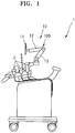
- FIG. 1 is a side view of a medical apparatus 1 according to an example embodiment.
- FIGS. 2A and 2B are views for explaining location movement of a display apparatus 11 in the medical apparatus 1 of FIG. 1 .
- the medical apparatus 1 may include a medical image acquiring unit 2 and a display supporting structure 10.
- the display supporting structure 10 includes a display apparatus 11 and an arm structure 100.
- the medical image acquiring unit 2 irradiates an object and may receive radiation that has passed through an object or reflected by an object.
- the radiation may be an ultrasound, but is not limited thereto, and may also be another type of radiation for diagnosis, for example, an X-ray.
- the display apparatus 11 displays information obtained using the medical image acquiring unit 2.
- the display apparatus 11 may display a radiation image such as an ultrasound image.
- the radiation image is not limited thereto, and may also be an image for diagnosis of an object, for example, an X-ray image.
- a weight of the display apparatus 11 may be about 2 kg to about 10 kg.
- the arm structure 100 movably supports the display apparatus 11.
- the arm structure 100 supports the display apparatus 11 such that the display apparatus 11 is movable in a vertical direction up and down as illustrated in FIGS. 2A and 2B .
- the arm structure 100 may be a foldable structure.
- the arm structure 100 includes a first arm 12 supporting the display apparatus 11 and a second arm 13 that pivotably supports the first arm 12.
- the display apparatus 11 may be mounted at an end portion of the first arm 12. Diagnosis information about an object may be displayed by using the display apparatus 11.
- the second arm 13 may be pivotable relative to a main body of the medical apparatus 1.
- the arm structure 100 may have a structure in which the first arm 12 and the second arm 13 are unfolded to be away from each other as illustrated in FIG. 2A or the first arm 12 and the second arm 13 approach each other as illustrated in FIG. 2B .
- the display apparatus 11 When a manipulation force by a user acts on the display apparatus 11, the display apparatus 11 may be moved via the arm structure 100.
- the display apparatus 11 may be moved not only up and down but also back and forth.
- FIG. 3A is a view focusing on the first arm 12 that movably supports the display apparatus 11 in the medical apparatus 1 disclosed in FIG. 1 .
- FIG. 3B illustrates a modified example of the arm structure 100 of FIG. 3A .
- FIG. 4 is a conceptual diagram of the arm structure 100 of FIG. 3A . In FIGS. 3A and 3B , for convenience of description, the arm structure 100 from which a cover thereof is removed is illustrated.
- the first arm 12 is rotatably supported with respect to a base part 110 of the second arm 13.
- the arm structure 100 includes the base part 110, a movement frame 120, a first link 130, and an elastic compensation member 140.
- the display apparatus 11 is mounted at an end portion of the movement frame 120, and a load of the display apparatus 11 acts on the end portion of the movement frame 120.
- the movement frame 120 is movable relative to the base part 110.
- the first link 130 is disposed between the movement frame 120 and the base part 110, and connects the movement frame 120 and the base part 110 to each other.
- the first link 130 is rotatably connected to the base part 110 with respect to a first rotational axis R1 such that the movement frame 120 is movable relative to the base part 110.
- a first end portion of the first link 130 is connected to the base part 110, and a second end portion of the first link 130 is connected to the movement frame 120. As the second end portion of the first link 130 is connected to the movement frame 120, due to a load of the display apparatus 11 acting on the movement frame 120, a first torque T1 is applied to the first rotational axis R1.
- the elastic compensation member 140 is elastically deformable, and provides a second torque T2 acting in an opposite direction to the first torque T1 to the first rotational axis R1 so as to compensate for the first torque T1.
- a first end portion of the elastic compensation member 140 is connected to the base part 110, and provides a predetermined elastic force to the first link 130 via a second end portion of the elastic compensation member 140.
- a first connection point C1 to which the base part 110 and the first link 130 are connected and a second connection point C2 to which the base part 110 and the elastic compensation member 140 are connected are spaced apart from each other.
- the first torque T1 acting on the first rotational axis R1 may be offset, thereby enabling a user to move the display apparatus 11 with a relatively small force.
- a modulus of elasticity of the elastic compensation member 140 may be selected by considering the first torque T1.
- the modulus of elasticity may be a spring constant if the elastic compensation member 140 is a spring.
- a modulus of elasticity of the elastic compensation member 140 may be selected by considering the first torque T1 acting on the first rotational axis R1.
- the first torque T1 is set by a weight W of the display apparatus 11 and a distance between the first rotational axis R1 and a point to which the weight W of the display apparatus 11 is applied.
- the second torque T2 provided by the elastic compensation member 140 to the first rotational axis R1 may be determined by an elastic force F of the elastic compensation member 140, an angle ( ⁇ ) between the elastic compensation member 140 and the first link 130, and a distance between the first rotational axis R1 and a point to which the elastic force F of the elastic compensation member 140 is applied.
- the elastic force F of the elastic compensation member 140 is determined by a modulus of elasticity of the elastic compensation member 140 and a length variation of the elastic compensation member 140.
- a modulus of elasticity of the elastic compensation member 140 may be designed such that the second torque T2 offsets the first torque T1.
- the movement frame 120 supporting the display apparatus 11 While moving the display apparatus 11, the movement frame 120 supporting the display apparatus 11 is moved, and the first link 130 movably supporting the movement frame 120 is rotated with respect to the first rotational axis R1.
- a length of the elastic compensation member 140 providing a predetermined elastic force F to the first link 130 is varied.
- the elastic force F of the elastic compensation member 140 may be varied.
- a variation in the elastic force F of the elastic compensation member 140 may be varied according to a modulus of elasticity of the elastic compensation member 140. In other words, even if a length variation of the elastic compensation member 140 is uniform, the higher a modulus of an elasticity of the elastic compensation member 140, the greater is a variation in the elastic force F.
- the elastic compensation member 140 may be a member used inside the arm structure 100 that movably supports the display apparatus 11 in the medical apparatus 1. As the arm structure 100 has a relatively narrow internal space, an allowable length variation of the elastic compensation member 140 may be small. On the other hand, an elastic force F required to compensate for a predetermined load of the display apparatus 11 may be large. In order to fulfill these two requirements, the elastic compensation member 140 may have a high modulus of elasticity. For example, a modulus of elasticity of the elastic compensation member 140 may be about three to four times a modulus of elasticity of an elastic compensation member that is generally used to mount the arm structure 100. For example, a modulus of elasticity of the elastic compensation member 140 actually needed for mounting may be 0.5 kgf/mm or greater. However, a modulus of the elastic compensation member 140 may be 5 kgf/mm or less.
- a modulus of elasticity of the elastic compensation member 140 high, despite a small length variation of the elastic compensation member 140, a variation in an elastic force of the elastic compensation member 140 may be large. According to the variation in the elastic force of the elastic compensation member 140, a variation in the second torque T2 provided by the elastic compensation member 140 to the first rotational axis R1 may be increased.
- a structure that allows to reduce a variation in a length of the elastic compensation member 140 during rotation of the first link 130 is provided.
- a compensation member supporting portion 150 that supports the second end portion of the elastic compensation member 140 such that the second end portion of the elastic compensation member 140 is not fixed to the first link 130 but is movable is further included.
- a first end portion of the compensation member supporting portion 150 is rotatably connected with respect to the second rotational axis R2 of the movement frame 120.
- a third connection point C3 to which the first link 130 and the movement frame 120 are connected and a fourth connection point C4 to which a supporting portion of the elastic compensation member 140 and the movement frame 120 are connected may be spaced apart from each other.
- a second end portion of the compensation member supporting portion 150 is movable relative to the first link 130, and supports the second end portion of the elastic compensation member 140.
- the second end portion of the elastic compensation member 140 is not fixed to the first link 130 but is supported by the second end portion of the compensation member supporting portion 150.
- the compensation member supporting portion 150 While a location of the movement frame 120 is moved, the compensation member supporting portion 150 is rotated with respect to the second rotational axis R2, and the second end portion of the elastic compensation member 140 that is supported by the second end portion of the compensation member supporting portion 150 may be moved relative to the first link 130. As a location of the second end portion of the elastic compensation member 140 is moved, a distance between the second end portion of the elastic compensation member 140 and the first rotational axis R1 in a length direction of the first link 130 may be varied.
- the compensation member supporting portion 150 may be in a link form having a uniform length.
- the compensation member supporting portion 150 is not limited thereto, and may have a variously modified shape as long as the first end portion of the compensation member supporting portion 150 is rotatable with respect to the second rotational axis R2 and the second end portion thereof is movable and supports the second end portion of the elastic compensation member 140.
- a compensation member supporting portion 150a may be an elastic member formed to be elastically deformable.
- FIG. 6 is a conceptual diagram of an operation of an arm structure 1000 according to a comparative example, in which a second end portion of an elastic compensation member 140 is fixed to a first link 130.
- FIG. 7 is a conceptual diagram of an operation of the arm structure 100 according to the example embodiment, in which a second end portion of the elastic compensation member 140 is movable.
- a first end portion of the elastic compensation member 140 is connected to the second connection point C2, and the second end portion of the elastic compensation member 140 is fixed to a fixing point A of the first link 130.
- the second end portion of the elastic compensation member 140 is connected to the fixing point A of the first link 130, if the first link 130 is rotated with respect to the first rotational axis R1, the second end portion of the elastic compensation member 140 also rotates when the fixing point A of the first link 130 is rotated. Accordingly, a length X1 of the elastic compensation member 140 is changed to a length X10.
- a distance d1 between the second end portion of the elastic compensation member 140 and the first rotational axis R1 in a length direction of the first link 130 is constant.
- the first end portion of the elastic compensation member 140 is connected to the second connection point C2, and the second end portion of the elastic compensation member 140 is not fixed to the first link 130 but is movable.
- the length X10 of the elastic compensation member 140 is changed to a length X2 which is shorter than the length X10.
- the distance d1 between the second end portion of the elastic compensation member 140 and the first rotational axis R1 in the length direction of the first link 130 may be changed to a distance d2.
- a length variation of the elastic compensation member 140 may be reduced.
- a length variation of the elastic compensation member 140 having the second end portion that is movable relative to the first link 130 in the present embodiment is reduced compared to a length variation of the elastic compensation member 140 having the second end portion that is fixed with respect to the first link 130.
- a length variation of the elastic compensation member 140 according to the present embodiment may be reduced by about 30% compared to a length variation of an elastic compensation member having a second end portion that is fixed.
- a length variation of the elastic compensation member 140 may be 10% or less of a length of the elastic compensation member 140 when an angle of the first link 130 with respect to a horizontal direction is 0 degree. As described above, by reducing a length variation of the elastic compensation member 140, a variation in the second torque T2 provided by the elastic compensation member 140 may be reduced.
- FIG. 8 is a view for describing a deviation in a compensation force due to the elastic compensation member 140 in the arm structure 1000 according to the comparative example of FIG. 6 .
- FIG. 9 is a view for describing a deviation in a compensation force due to the elastic compensation member 140 in the arm structure 100 according to the example embodiment of FIG. 7 .
- values of the first torque T1 and the second torque T2 in which an influence of an angle of the first link 130 is not reflected are shown.
- the second torque T2 provided by the elastic compensation member 140 during rotation of the first link 130 is about 2.7 kgf to about 5.1 kgf in an opposite direction to the first torque T1. Accordingly, when an angle of the first link 130 is +30 degrees, the second torque T2 is smaller than the first torque T1 by 1.3 kgf, whereas if an angle of the first link 130 is -30 degrees, the second torque T2 is greater than the first torque T1 by 1.1 kgf.
- the second torque T2 provided by the elastic compensation member 140 during rotation of the first link 130 is about 3.5 kgf to about 4.2 kgf in an opposite direction to the first torque T1. Accordingly, when an angle of the first link 130 is +30 degrees, the second torque T2 is greater than the first torque T1 by 0.2 kgf, whereas if an angle of the first link 130 is -30 degrees, the second torque T2 is greater than the first torque T1 by 0.5 kgf.
- a deviation between the second torque T2 provided by the elastic compensation member 140 and the first torque T1 may be remarkably reduced.
- a deviation between the second torque T2 and the first torque T1 may be reduced to 1 kgf or less.
- a deviation between the second torque T2 and the first torque T1 may be reduced to 0.5 kgf or less.
- the arm structure 100 further includes a distance variation guide 160 configured to vary a distance between the first connection point C1 and the second end portion of the elastic compensation member 140 in a direction perpendicular to the length direction of the first link 130.
- the distance variation guide 160 may be used to vary a distance between the first connection point C1 and the second end portion of the elastic compensation member 140 in a direction perpendicular to the length direction of the first link 130.
- the distance variation guide 160 may be disposed in the first link 130, and may have an inclined surface 161 having a height that varies in the direction perpendicular to the length direction of the first link 130, along the length direction of the first link 130.
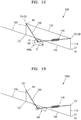
- FIG. 10A illustrates a variation in a height of inclined surfaces 161 and 161a in a length direction of the first link 130 for explaining example embodiments of the inclined surface 161 of FIG. 3A .
- FIG. 10B illustrates a variation in a height of an inclined surface of a first link in a length direction, for explaining a modified example of an inclined surface of a distance variation guide of FIG. 3A .
- x denotes a location of the inclined surface 161 in a length direction of the first link 130
- y denotes a height of the inclined surface 161.
- a negative (-) symbol is used for a height of the inclined surface 161 below a height of the first connection point C1 and the third connection point C3 of the first link 130.
- the inclined surface 161 may be formed to have a linearly varying height in a direction perpendicular to the length direction of the first link 130 along the length direction of the first link 130.
- a height variation of the inclined surface 161 may be linear.
- the inclined surface 161 may be designed in various manners.
- the inclined surface 161 may have a height that varies non-linearly in a direction perpendicular to the length direction of the first link 130 along the length direction of the first link 130.
- a height variation of the inclined surface 161 may be in a curved form.
- a deviation in a compensation force may be set to 20 gf or less.
- the inclined surface 161 of the distance variation guide 160 may be disposed to protrude outwardly from the first link 130.
- arrangement of the distance variation guide 160 is not limited thereto, and the distance variation guide 160 may also be disposed inside the first link 130.
- the inclined surface 161 of the distance variation guide 160 may be disposed in the first link 130.
- the inclined surface 161 may have a height that varies from a virtual line connecting the first connection point C1 and the third connection point C3 in a direction perpendicular to the length direction of the first link 130.
- a roller 151 rotating to move along the inclined surface 161 may be mounted at an end portion of the compensation member supporting portion 150.
- the roller 151 may have a circular cross-sectional shape.
- FIG. 11 is a view for describing an operation of the distance variation guide 160 when the first link 130 of FIG. 4 is rotated.
- the compensation member supporting portion 150 is rotated in a counter-clockwise direction with respect to the second rotational axis R2, and the second end portion of the elastic compensation member 140 supported by the second end portion of the compensation member supporting portion 150 is moved relative to the first link 130.
- the second end portion of the elastic compensation member 140 is moved from a virtual line connecting the first connection point C1 and the third connection point C3 in a length direction of the first link 130 and in a direction perpendicular to the length direction of the first link 30.
- a variation of the second torque T2 due to the elastic compensation member 140 occurring during location movement of the movement frame 120 may be designed to correspond to a variation of the first torque T1.
- a guide variation guide 160a may be a cam 162 that is rotatable and mounted at the second end portion of the compensation member supporting portion 150.
- a distance h1 and a distance h2 from a rotational axis of the cam 162 to an external surface thereof vary, and the cam 162 may be rotatable along a surface of the first link 130.
- the second end portion of the elastic compensation member 140 may be connected to the rotational axis of the cam 162.
- a distance between the rotational axis of the cam 162 and the first link 130 may be varied. Accordingly, a distance between the second end portion of the elastic compensation member 140 and the first link 130 in the direction perpendicular to the length direction of the first link 130 may be varied.
- the arm structure 100 may further include a second link 170 that is parallel to the first link 130 and has a first end portion connected to the base part 110 and a second end portion connected to the movement frame 120.
- a distance between a fifth connection point C5 to which the second link 170 and the movement frame 120 are connected and the third connection point C3 may be identical to a distance between a sixth connection point C6 to which the second link 170 and the base part 110 are connected and the first connection point C1.
- the fifth connection point C5 may be identical to the fourth connection point C4, and the sixth connection point C6 may be identical to the second connection point C2.
- the fifth and sixth connection points C5 and C6 may not necessarily be identical to the fourth connection point C4 and the second connection point C2, respectively, and may be different points according to necessity.
- Two end portions of the first link 130 may be pivotable relative to the base part 110 and the movement frame 120, and two end portions of the second link 170 may be pivotable relative to the base part 110 and the movement frame 120.
- a screen direction of the display apparatus 11 mounted on the movement frame 120 may be maintained uniform.
- the arm structure 100 of the example embodiment does not necessarily have to include the second link 170, and the second link 170 may be omitted according to necessity.
- an arm structure 100a may not include the second link 170 as illustrated in FIG. 13 .
- the medical apparatus and the display supporting structure and the arm structure of the example embodiments, by minimizing a length variation of the elastic compensation member according to location movement of the display apparatus, compensation deviation between a torque provided by the elastic compensation member and a torque acting due to a load of the display apparatus may be reduced.
Landscapes
- Health & Medical Sciences (AREA)
- Life Sciences & Earth Sciences (AREA)
- Engineering & Computer Science (AREA)
- Medical Informatics (AREA)
- Surgery (AREA)
- General Health & Medical Sciences (AREA)
- Veterinary Medicine (AREA)
- Biomedical Technology (AREA)
- Heart & Thoracic Surgery (AREA)
- Public Health (AREA)
- Molecular Biology (AREA)
- Animal Behavior & Ethology (AREA)
- Pathology (AREA)
- Physics & Mathematics (AREA)
- Biophysics (AREA)
- Nuclear Medicine, Radiotherapy & Molecular Imaging (AREA)
- General Engineering & Computer Science (AREA)
- Radiology & Medical Imaging (AREA)
- Mechanical Engineering (AREA)
- Human Computer Interaction (AREA)
- Optics & Photonics (AREA)
- High Energy & Nuclear Physics (AREA)
- Oral & Maxillofacial Surgery (AREA)
- Manipulator (AREA)
- Apparatus For Radiation Diagnosis (AREA)
Claims (13)
- Armstruktur (100) zum beweglichen Tragen einer Anzeigevorrichtung (11), wobei die Armstruktur (100) Folgendes umfasst:einen Basisteil (110);einen Bewegungsrahmen (120), der derart konfiguriert ist, dass eine vorbestimmte Last darauf aufgebracht werden kann;ein erstes Verbindungselement (130), um den Bewegungsrahmen (120) und den Basisteil (110) miteinander zu verbinden, wobei das erste Verbindungselement (130) in Bezug auf eine erste Drehachse (R1) des Basisteils (110) drehbar verbunden ist, so dass der Bewegungsrahmen (120) relativ zu dem Basisteil (110) beweglich ist und ein erstes Drehmoment (T1) aufgrund der Last, die auf den Bewegungsrahmen (120) aufgebracht wird, auf die erste Drehachse (R1) wirkt;ein elastisches Ausgleichselement (140), das elastisch verformbar ist und einen ersten Endabschnitt, der mit dem Basisteil (110) verbunden ist, aufweist, wobei das elastische Ausgleichselement (140) der ersten Drehachse (R1) ein zweites Drehmoment (T2) bereitstellt, das in entgegengesetzter Richtung zu dem ersten Drehmoment (T1) wirkt, um das erste Drehmoment (T1) auszugleichen;einen Ausgleichselement-Trägerabschnitt (150) mit einem ersten Endabschnitt, der drehbar mit einer zweiten Drehachse (R2) des Bewegungsrahmens (120) verbunden ist, und einem zweiten Endabschnitt, der in Bezug auf das erste Verbindungselement (130) drehbar ist und einen zweiten Endabschnitt des elastischen Ausgleichselements (140), der nicht an dem ersten Verbindungselement (130) befestigt ist, trägt; gekennzeichnet durcheine Abstandsvariierungsführung (160), die dazu konfiguriert ist, einen Abstand zwischen dem zweiten Endabschnitt des elastischen Ausgleichselements (140) und dem ersten Verbindungselement (130) in einer Richtung rechtwinklig zu einer Längenrichtung des ersten Verbindungselements (130) zu variieren, und derart konfiguriert, dass,während der Bewegungsrahmen (120) bewegt wird, das erste Verbindungselement (130) in Bezug auf die erste Drehachse (R1) gedreht wird, und der Ausgleichselement-Trägerabschnitt (150) sich in Bezug auf die zweite Drehachse (R2) dreht, und der zweite Endabschnitt des elastischen Ausgleichselements (140) in Bezug auf das erste Verbindungselement (130) in der Längenrichtung des ersten Verbindungselementes (130) und in der Richtung rechtwinklig zu der Längenrichtung des ersten Verbindungselements (130) bewegt wird.
- Medizinische Vorrichtung (1) umfassend eine Einheit (2) zur Erfassung eines medizinischen Bildes, eine Anzeigevorrichtung (11), die aus der Einheit (2) zur Erfassung eines medizinischen Bildes erhaltene Informationen anzeigt, und eine Armstruktur (100) nach Anspruch 1.
- Medizinische Vorrichtung nach Anspruch 2, wobei ein erster Verbindungspunkt (C1), mit dem der Basisteil (110) und das erste Verbindungselement (130) verbunden sind, und ein zweiter Verbindungspunkt (C2), mit dem das Basisteil (110) und das elastische Ausgleichselement (140) verbunden sind, voneinander beabstandet sind.
- Medizinische Vorrichtung nach Anspruch 3, wobei ein dritter Verbindungspunkt (C3), mit dem das erste Verbindungselement (130) und der Bewegungsrahmen (120) verbunden sind, und ein vierter Verbindungspunkt (C4), mit dem der Ausgleichselement-Trägerabschnitt (150) und der Bewegungsrahmen (120) verbunden sind, voneinander beabstandet sind.
- Medizinische Vorrichtung nach Anspruch 3, die derart konfiguriert ist, dass während das erste Verbindungselement (130) in Bezug auf die erste Drehachse (R1) gedreht wird, ein Abstand zwischen dem ersten Verbindungspunkt (C1) und dem zweiten Endabschnitt des elastischen Ausgleichselements (140) in der Längenrichtung des ersten Verbindungselementes (130) sowie ein Abstand zwischen dem ersten Verbindungselement (C1) und dem zweiten Endabschnitt des elastischen Ausgleichselements (140) in der Richtung rechtwinklig zu der Längenrichtung des ersten Verbindungselements (130) variieren.
- Medizinische Vorrichtung nach Anspruch 4, wobei die Abstandsvariierungsführung (160) in dem ersten Verbindungselement (130) vorgesehen ist und eine geneigte Oberfläche (161) aufweist, deren Höhe in der Richtung rechtwinklig zu der Längenrichtung des ersten Verbindungselements (130) entlang der Längenrichtung des ersten Verbindungselements (130) variiert, und
wobei der Ausgleichselement-Trägerabschnitt (150) weiterhin eine kreisförmige Walze (151) an dem zweiten Endabschnitt des Ausgleichselement-Trägerabschnitts (150) umfasst,
wobei die Walze (151) des Ausgleichselement-Trägerabschnitts (150) dazu konfiguriert ist, sich entlang der geneigten Oberfläche (161) zu bewegen. - Medizinische Vorrichtung nach Anspruch 6, wobei die geneigte Oberfläche (161) an einem inneren Abschnitt des ersten Verbindungselements (130) angeordnet ist und eine Höhe aufweist, die von einer virtuellen Linie, welche den ersten Verbindungspunkt (C1) mit dem dritten Verbindungspunkt (C3) verbindet, in der Richtung rechtwinklig zu der Längenrichtung des ersten Verbindungselements (130) variiert.
- Medizinische Vorrichtung nach Anspruch 6, wobei die Höhe der geneigten Oberfläche (161) in der Richtung rechtwinklig zu der Längenrichtung des ersten Verbindungselements (130) linear oder nicht-linear variiert.
- Medizinische Vorrichtung nach Anspruch 4, wobei die Abstandsvariierungsführung (160) weiterhin einen Nocken (162) umfasst, der an dem zweiten Endabschnitt des Ausgleichselement-Trägerabschnitts (150) angeordnet und an dem ersten Verbindungselement (130) entlang drehbar ist.
- Medizinische Vorrichtung nach Anspruch 4, weiterhin umfassend ein zweites Verbindungselement (170), das parallel zu dem ersten Verbindungselement (130) ist und einen ersten Endabschnitt, der mit dem Basisteil (110) verbunden ist, sowie einen zweiten Endabschnitt, der mit dem Bewegungsrahmen (120) verbunden ist, aufweist.
- Medizinische Vorrichtung nach Anspruch 10, wobei ein Abstand zwischen einem fünften Verbindungspunkt (C5), mit dem das zweite Verbindungselement (170) und der Bewegungsrahmen (120) verbunden sind, und dem dritten Verbindungspunkt (C3) identisch ist mit einem Abstand zwischen einem sechsten Verbindungspunkt (C6), mit dem das zweite Verbindungselement (170) und der Basisteil (110) verbunden sind, und dem ersten Verbindungspunkt.
- Medizinische Vorrichtung nach Anspruch 11, wobei zwei Endabschnitte des ersten Verbindungselements (130) relativ zu dem Basisteil (110) und dem Bewegungsrahmen (120) schwenkbar sind, und zwei Endabschnitte des zweiten Verbindungselements (170) relativ zu dem Basisteil (110) und dem Bewegungsrahmen (120) schwenkbar sind, so dass während das erste Verbindungselement und das zweite Verbindungselement sich in Bezug auf den Basisteil derart drehen, dass der Bewegungsrahmen bewegt wird, eine Bildschirmrichtung der an dem Bewegungsrahmen montierten Anzeigevorrichtung (11), gleich bleibt.
- Anzeigetragstruktur (10) umfassend eine Anzeigevorrichtung (11) und eine Armstruktur (100) nach Anspruch 1, welche Anzeigetragstruktur die Anzeigevorrichtung (11) beweglich trägt.
Applications Claiming Priority (1)
| Application Number | Priority Date | Filing Date | Title |
|---|---|---|---|
| KR1020160153316A KR101830886B1 (ko) | 2016-11-17 | 2016-11-17 | 의료 기기, 이에 사용되는 디스플레이 지지 구조물 및 아암 구조물 |
Publications (2)
| Publication Number | Publication Date |
|---|---|
| EP3323348A1 EP3323348A1 (de) | 2018-05-23 |
| EP3323348B1 true EP3323348B1 (de) | 2019-04-17 |
Family
ID=60244929
Family Applications (1)
| Application Number | Title | Priority Date | Filing Date |
|---|---|---|---|
| EP17199644.0A Not-in-force EP3323348B1 (de) | 2016-11-17 | 2017-11-02 | Medizinische vorrichtung und darin verwendete anzeigetragstruktur und armstruktur |
Country Status (4)
| Country | Link |
|---|---|
| US (1) | US10197218B2 (de) |
| EP (1) | EP3323348B1 (de) |
| KR (1) | KR101830886B1 (de) |
| CN (1) | CN108066013A (de) |
Families Citing this family (5)
| Publication number | Priority date | Publication date | Assignee | Title |
|---|---|---|---|---|
| JP6395650B2 (ja) * | 2015-03-23 | 2018-09-26 | 株式会社日立製作所 | X線撮影装置 |
| KR102615049B1 (ko) * | 2018-03-07 | 2023-12-19 | 삼성메디슨 주식회사 | 초음파진단장치 |
| KR102751106B1 (ko) * | 2019-10-11 | 2025-01-06 | 주식회사 엘지에너지솔루션 | 배터리 운반 장치 |
| KR20240165130A (ko) * | 2023-05-15 | 2024-11-22 | 삼성메디슨 주식회사 | 중력보상 조절 장치 및 이를 포함하는 초음파 진단장치 |
| JP2025073458A (ja) * | 2023-10-26 | 2025-05-13 | 富士フイルム株式会社 | マンモグラフィ装置、マンモグラフィ装置の表示方法、及び医用画像取得システム |
Family Cites Families (24)
| Publication number | Priority date | Publication date | Assignee | Title |
|---|---|---|---|---|
| DE8429928U1 (de) * | 1984-10-11 | 1986-02-13 | Sträter, Fritz, 5882 Meinerzhagen | Konzepthalter zur Anwendung an Schreib-, Zeichen-, Bildschirmarbeitsplätzen und dgl. |
| DE3921857A1 (de) * | 1989-07-04 | 1991-01-17 | Wild Leitz Ag | Mit zusatzvorrichtungen ausgestattetes stativ fuer die halterung eines frei positionierbaren geraetes |
| US5288043A (en) * | 1992-09-11 | 1994-02-22 | Tigliev George S | Balanced suspension system for surgical microscope |
| DE10042272B4 (de) * | 2000-08-29 | 2012-10-31 | Leica Instruments (Singapore) Pte. Ltd. | Stativanordnung |
| US6819550B2 (en) * | 2001-11-08 | 2004-11-16 | Apple Computer, Inc. | Computer controlled display device |
| US6663569B1 (en) | 2002-05-23 | 2003-12-16 | Koninklijke Philips Electronics N.V. | Diagnostic ultrasound system cart with variable elevation control panel |
| DE102005017487A1 (de) * | 2005-04-15 | 2006-10-19 | Sachtler Gmbh & Co. Kg | Federarm und Körperstativ |
| KR20070097737A (ko) | 2006-03-29 | 2007-10-05 | 주식회사 메디슨 | 초음파 진단 장치의 모니터 지지 조립체 |
| JP4393506B2 (ja) * | 2006-11-27 | 2010-01-06 | 株式会社日立メディコ | 超音波診断装置 |
| CN201206708Y (zh) * | 2008-05-29 | 2009-03-11 | 富鸿齐科技股份有限公司 | 具有水平位移补偿功能的支撑架 |
| CN201425148Y (zh) * | 2009-05-12 | 2010-03-17 | 昆山义丰板金科技有限公司 | 平板显示器万向支架 |
| CN102471043B (zh) * | 2009-07-15 | 2014-12-24 | 学校法人庆应义塾 | 载荷补偿装置 |
| JP5489157B2 (ja) * | 2010-02-17 | 2014-05-14 | ジーイー・メディカル・システムズ・グローバル・テクノロジー・カンパニー・エルエルシー | 超音波診断装置 |
| GB2481047A (en) * | 2010-06-09 | 2011-12-14 | Colebrook Bosson & Saunders Products Ltd | A mounting system for pivotally mounting a flat screen display |
| EP2580513A1 (de) * | 2010-06-09 | 2013-04-17 | Innovative Office Products, Inc. | Monitorgelenkarm mit kabel und feder |
| JP5918232B2 (ja) * | 2010-07-08 | 2016-05-18 | サウスコ,インコーポレイティド | ディスプレイ支持装置 |
| US8827948B2 (en) * | 2010-09-17 | 2014-09-09 | Hansen Medical, Inc. | Steerable catheters |
| JP5373830B2 (ja) * | 2011-01-19 | 2013-12-18 | ジーイー・メディカル・システムズ・グローバル・テクノロジー・カンパニー・エルエルシー | 支持アーム及び画像表示装置 |
| DE102011004926A1 (de) * | 2011-03-01 | 2012-09-06 | Karl Storz Gmbh & Co. Kg | Einstellbare Haltevorrichtung für ein Endoskop |
| KR101901590B1 (ko) * | 2012-01-03 | 2018-09-27 | 삼성메디슨 주식회사 | 초음파 진단장치 |
| US9657889B1 (en) * | 2013-03-15 | 2017-05-23 | Humanscale Corporation | Adjustable support arm |
| US9033292B2 (en) * | 2013-08-21 | 2015-05-19 | Continew Inc. | Load supporting apparatus |
| KR102253243B1 (ko) | 2014-02-18 | 2021-05-20 | 삼성전자주식회사 | 보행 보조장치 및 보행 보조장치의 제어 방법 |
| KR101656614B1 (ko) | 2015-04-09 | 2016-09-09 | 장근대 | 모니터 거치장치 |
-
2016
- 2016-11-17 KR KR1020160153316A patent/KR101830886B1/ko not_active Expired - Fee Related
-
2017
- 2017-11-02 EP EP17199644.0A patent/EP3323348B1/de not_active Not-in-force
- 2017-11-09 US US15/808,332 patent/US10197218B2/en not_active Expired - Fee Related
- 2017-11-17 CN CN201711144323.8A patent/CN108066013A/zh active Pending
Non-Patent Citations (1)
| Title |
|---|
| None * |
Also Published As
| Publication number | Publication date |
|---|---|
| KR101830886B1 (ko) | 2018-02-21 |
| EP3323348A1 (de) | 2018-05-23 |
| CN108066013A (zh) | 2018-05-25 |
| US10197218B2 (en) | 2019-02-05 |
| US20180135797A1 (en) | 2018-05-17 |
Similar Documents
| Publication | Publication Date | Title |
|---|---|---|
| EP3323348A1 (de) | Medizinische vorrichtung und darin verwendete anzeigetragstruktur und armstruktur | |
| US7988357B2 (en) | X-ray system | |
| US9549706B2 (en) | Cradle drive mechanism, a table, and a patient imaging and carrying apparatus | |
| US20130028391A1 (en) | Head holder, imaging table, and x-ray ct apparatus | |
| EP2874542B1 (de) | Drehbare gantry für multimodale abbildungssysteme | |
| JP5729952B2 (ja) | 医学的な撮像のための放射源及び放射ディテクタを柔軟に位置決めするための装置 | |
| JP5501385B2 (ja) | 断層合成撮影用x線装置 | |
| JP6174560B2 (ja) | 口腔内x線装置のためのアーム構造 | |
| US20060079763A1 (en) | Backprojected patient multimedia display | |
| US20190346080A1 (en) | Stand device | |
| CN106714692A (zh) | 用于对成像系统中的旋转臂配重平衡的装置 | |
| CN103815970A (zh) | 骨科机器人导针定位器、导航装置及定位系统 | |
| JP5985601B2 (ja) | 口腔内x線装置のためのアーム構造のアーム | |
| US10881363B2 (en) | Imaging system with dynamic beam size limitation | |
| KR101794291B1 (ko) | 영상촬영후 영상데이터와 영상이미지 합성을 위한 영상처리시스템 | |
| US20060074305A1 (en) | Patient multimedia display | |
| WO2020048896A1 (en) | An x-ray imaging device | |
| EP3111845B1 (de) | Verfahren und vorrichtung zur erfassung von panoramischen und cbct-volumetrischen röntgenaufnahmen | |
| CN104173068B (zh) | 用于拼接的x射线成像装置和所属的方法 | |
| US11039799B2 (en) | Bearing system for cone beam computed tomography | |
| KR100920751B1 (ko) | 3차원 촬영위치 선정을 위한 엑스선 촬영장치의 디지털 스탠드 | |
| US10460848B2 (en) | Device for suspending an x-ray grid, arrangement with an x-ray grid and method for operating an x-ray grid | |
| RU2202953C2 (ru) | Рентгеновский стол-штатив поворотный | |
| CN102688059B (zh) | X射线设备 | |
| US9119541B2 (en) | Eyewear for patient prompting |
Legal Events
| Date | Code | Title | Description |
|---|---|---|---|
| PUAI | Public reference made under article 153(3) epc to a published international application that has entered the european phase |
Free format text: ORIGINAL CODE: 0009012 |
|
| STAA | Information on the status of an ep patent application or granted ep patent |
Free format text: STATUS: REQUEST FOR EXAMINATION WAS MADE |
|
| 17P | Request for examination filed |
Effective date: 20171102 |
|
| AK | Designated contracting states |
Kind code of ref document: A1 Designated state(s): AL AT BE BG CH CY CZ DE DK EE ES FI FR GB GR HR HU IE IS IT LI LT LU LV MC MK MT NL NO PL PT RO RS SE SI SK SM TR |
|
| AX | Request for extension of the european patent |
Extension state: BA ME |
|
| RAP1 | Party data changed (applicant data changed or rights of an application transferred) |
Owner name: SAMSUNG MEDISON CO., LTD. |
|
| GRAP | Despatch of communication of intention to grant a patent |
Free format text: ORIGINAL CODE: EPIDOSNIGR1 |
|
| STAA | Information on the status of an ep patent application or granted ep patent |
Free format text: STATUS: GRANT OF PATENT IS INTENDED |
|
| RIC1 | Information provided on ipc code assigned before grant |
Ipc: A61B 5/00 20060101ALI20181122BHEP Ipc: A61B 6/00 20060101ALI20181122BHEP Ipc: F16M 13/02 20060101ALI20181122BHEP Ipc: F16M 11/04 20060101ALN20181122BHEP Ipc: A61B 8/00 20060101AFI20181122BHEP Ipc: F16M 11/10 20060101ALI20181122BHEP Ipc: F16M 11/38 20060101ALI20181122BHEP |
|
| INTG | Intention to grant announced |
Effective date: 20181217 |
|
| RIN1 | Information on inventor provided before grant (corrected) |
Inventor name: LEE, JAE-WON Inventor name: SHIN, JEA-EUN Inventor name: SHIN, SOK-JAE |
|
| GRAS | Grant fee paid |
Free format text: ORIGINAL CODE: EPIDOSNIGR3 |
|
| GRAA | (expected) grant |
Free format text: ORIGINAL CODE: 0009210 |
|
| STAA | Information on the status of an ep patent application or granted ep patent |
Free format text: STATUS: THE PATENT HAS BEEN GRANTED |
|
| AK | Designated contracting states |
Kind code of ref document: B1 Designated state(s): AL AT BE BG CH CY CZ DE DK EE ES FI FR GB GR HR HU IE IS IT LI LT LU LV MC MK MT NL NO PL PT RO RS SE SI SK SM TR |
|
| REG | Reference to a national code |
Ref country code: GB Ref legal event code: FG4D |
|
| REG | Reference to a national code |
Ref country code: CH Ref legal event code: EP |
|
| REG | Reference to a national code |
Ref country code: DE Ref legal event code: R096 Ref document number: 602017003363 Country of ref document: DE |
|
| REG | Reference to a national code |
Ref country code: AT Ref legal event code: REF Ref document number: 1120679 Country of ref document: AT Kind code of ref document: T Effective date: 20190515 Ref country code: IE Ref legal event code: FG4D |
|
| REG | Reference to a national code |
Ref country code: NL Ref legal event code: MP Effective date: 20190417 |
|
| REG | Reference to a national code |
Ref country code: LT Ref legal event code: MG4D |
|
| PG25 | Lapsed in a contracting state [announced via postgrant information from national office to epo] |
Ref country code: NL Free format text: LAPSE BECAUSE OF FAILURE TO SUBMIT A TRANSLATION OF THE DESCRIPTION OR TO PAY THE FEE WITHIN THE PRESCRIBED TIME-LIMIT Effective date: 20190417 |
|
| PG25 | Lapsed in a contracting state [announced via postgrant information from national office to epo] |
Ref country code: ES Free format text: LAPSE BECAUSE OF FAILURE TO SUBMIT A TRANSLATION OF THE DESCRIPTION OR TO PAY THE FEE WITHIN THE PRESCRIBED TIME-LIMIT Effective date: 20190417 Ref country code: HR Free format text: LAPSE BECAUSE OF FAILURE TO SUBMIT A TRANSLATION OF THE DESCRIPTION OR TO PAY THE FEE WITHIN THE PRESCRIBED TIME-LIMIT Effective date: 20190417 Ref country code: LT Free format text: LAPSE BECAUSE OF FAILURE TO SUBMIT A TRANSLATION OF THE DESCRIPTION OR TO PAY THE FEE WITHIN THE PRESCRIBED TIME-LIMIT Effective date: 20190417 Ref country code: PT Free format text: LAPSE BECAUSE OF FAILURE TO SUBMIT A TRANSLATION OF THE DESCRIPTION OR TO PAY THE FEE WITHIN THE PRESCRIBED TIME-LIMIT Effective date: 20190817 Ref country code: NO Free format text: LAPSE BECAUSE OF FAILURE TO SUBMIT A TRANSLATION OF THE DESCRIPTION OR TO PAY THE FEE WITHIN THE PRESCRIBED TIME-LIMIT Effective date: 20190717 Ref country code: FI Free format text: LAPSE BECAUSE OF FAILURE TO SUBMIT A TRANSLATION OF THE DESCRIPTION OR TO PAY THE FEE WITHIN THE PRESCRIBED TIME-LIMIT Effective date: 20190417 Ref country code: SE Free format text: LAPSE BECAUSE OF FAILURE TO SUBMIT A TRANSLATION OF THE DESCRIPTION OR TO PAY THE FEE WITHIN THE PRESCRIBED TIME-LIMIT Effective date: 20190417 Ref country code: AL Free format text: LAPSE BECAUSE OF FAILURE TO SUBMIT A TRANSLATION OF THE DESCRIPTION OR TO PAY THE FEE WITHIN THE PRESCRIBED TIME-LIMIT Effective date: 20190417 |
|
| PG25 | Lapsed in a contracting state [announced via postgrant information from national office to epo] |
Ref country code: LV Free format text: LAPSE BECAUSE OF FAILURE TO SUBMIT A TRANSLATION OF THE DESCRIPTION OR TO PAY THE FEE WITHIN THE PRESCRIBED TIME-LIMIT Effective date: 20190417 Ref country code: PL Free format text: LAPSE BECAUSE OF FAILURE TO SUBMIT A TRANSLATION OF THE DESCRIPTION OR TO PAY THE FEE WITHIN THE PRESCRIBED TIME-LIMIT Effective date: 20190417 Ref country code: BG Free format text: LAPSE BECAUSE OF FAILURE TO SUBMIT A TRANSLATION OF THE DESCRIPTION OR TO PAY THE FEE WITHIN THE PRESCRIBED TIME-LIMIT Effective date: 20190717 Ref country code: GR Free format text: LAPSE BECAUSE OF FAILURE TO SUBMIT A TRANSLATION OF THE DESCRIPTION OR TO PAY THE FEE WITHIN THE PRESCRIBED TIME-LIMIT Effective date: 20190718 Ref country code: RS Free format text: LAPSE BECAUSE OF FAILURE TO SUBMIT A TRANSLATION OF THE DESCRIPTION OR TO PAY THE FEE WITHIN THE PRESCRIBED TIME-LIMIT Effective date: 20190417 |
|
| REG | Reference to a national code |
Ref country code: AT Ref legal event code: MK05 Ref document number: 1120679 Country of ref document: AT Kind code of ref document: T Effective date: 20190417 |
|
| PG25 | Lapsed in a contracting state [announced via postgrant information from national office to epo] |
Ref country code: IS Free format text: LAPSE BECAUSE OF FAILURE TO SUBMIT A TRANSLATION OF THE DESCRIPTION OR TO PAY THE FEE WITHIN THE PRESCRIBED TIME-LIMIT Effective date: 20190817 |
|
| REG | Reference to a national code |
Ref country code: DE Ref legal event code: R097 Ref document number: 602017003363 Country of ref document: DE |
|
| PG25 | Lapsed in a contracting state [announced via postgrant information from national office to epo] |
Ref country code: CZ Free format text: LAPSE BECAUSE OF FAILURE TO SUBMIT A TRANSLATION OF THE DESCRIPTION OR TO PAY THE FEE WITHIN THE PRESCRIBED TIME-LIMIT Effective date: 20190417 Ref country code: RO Free format text: LAPSE BECAUSE OF FAILURE TO SUBMIT A TRANSLATION OF THE DESCRIPTION OR TO PAY THE FEE WITHIN THE PRESCRIBED TIME-LIMIT Effective date: 20190417 Ref country code: EE Free format text: LAPSE BECAUSE OF FAILURE TO SUBMIT A TRANSLATION OF THE DESCRIPTION OR TO PAY THE FEE WITHIN THE PRESCRIBED TIME-LIMIT Effective date: 20190417 Ref country code: SK Free format text: LAPSE BECAUSE OF FAILURE TO SUBMIT A TRANSLATION OF THE DESCRIPTION OR TO PAY THE FEE WITHIN THE PRESCRIBED TIME-LIMIT Effective date: 20190417 Ref country code: AT Free format text: LAPSE BECAUSE OF FAILURE TO SUBMIT A TRANSLATION OF THE DESCRIPTION OR TO PAY THE FEE WITHIN THE PRESCRIBED TIME-LIMIT Effective date: 20190417 Ref country code: DK Free format text: LAPSE BECAUSE OF FAILURE TO SUBMIT A TRANSLATION OF THE DESCRIPTION OR TO PAY THE FEE WITHIN THE PRESCRIBED TIME-LIMIT Effective date: 20190417 |
|
| PGFP | Annual fee paid to national office [announced via postgrant information from national office to epo] |
Ref country code: DE Payment date: 20191004 Year of fee payment: 3 |
|
| PLBE | No opposition filed within time limit |
Free format text: ORIGINAL CODE: 0009261 |
|
| STAA | Information on the status of an ep patent application or granted ep patent |
Free format text: STATUS: NO OPPOSITION FILED WITHIN TIME LIMIT |
|
| PG25 | Lapsed in a contracting state [announced via postgrant information from national office to epo] |
Ref country code: SM Free format text: LAPSE BECAUSE OF FAILURE TO SUBMIT A TRANSLATION OF THE DESCRIPTION OR TO PAY THE FEE WITHIN THE PRESCRIBED TIME-LIMIT Effective date: 20190417 |
|
| PGFP | Annual fee paid to national office [announced via postgrant information from national office to epo] |
Ref country code: FR Payment date: 20191008 Year of fee payment: 3 |
|
| 26N | No opposition filed |
Effective date: 20200120 |
|
| PG25 | Lapsed in a contracting state [announced via postgrant information from national office to epo] |
Ref country code: TR Free format text: LAPSE BECAUSE OF FAILURE TO SUBMIT A TRANSLATION OF THE DESCRIPTION OR TO PAY THE FEE WITHIN THE PRESCRIBED TIME-LIMIT Effective date: 20190417 |
|
| PG25 | Lapsed in a contracting state [announced via postgrant information from national office to epo] |
Ref country code: SI Free format text: LAPSE BECAUSE OF FAILURE TO SUBMIT A TRANSLATION OF THE DESCRIPTION OR TO PAY THE FEE WITHIN THE PRESCRIBED TIME-LIMIT Effective date: 20190417 |
|
| PG25 | Lapsed in a contracting state [announced via postgrant information from national office to epo] |
Ref country code: LU Free format text: LAPSE BECAUSE OF NON-PAYMENT OF DUE FEES Effective date: 20191102 Ref country code: MC Free format text: LAPSE BECAUSE OF FAILURE TO SUBMIT A TRANSLATION OF THE DESCRIPTION OR TO PAY THE FEE WITHIN THE PRESCRIBED TIME-LIMIT Effective date: 20190417 |
|
| REG | Reference to a national code |
Ref country code: BE Ref legal event code: MM Effective date: 20191130 |
|
| PG25 | Lapsed in a contracting state [announced via postgrant information from national office to epo] |
Ref country code: IE Free format text: LAPSE BECAUSE OF NON-PAYMENT OF DUE FEES Effective date: 20191102 |
|
| PG25 | Lapsed in a contracting state [announced via postgrant information from national office to epo] |
Ref country code: BE Free format text: LAPSE BECAUSE OF NON-PAYMENT OF DUE FEES Effective date: 20191130 |
|
| PGFP | Annual fee paid to national office [announced via postgrant information from national office to epo] |
Ref country code: IT Payment date: 20201130 Year of fee payment: 4 |
|
| PG25 | Lapsed in a contracting state [announced via postgrant information from national office to epo] |
Ref country code: CY Free format text: LAPSE BECAUSE OF FAILURE TO SUBMIT A TRANSLATION OF THE DESCRIPTION OR TO PAY THE FEE WITHIN THE PRESCRIBED TIME-LIMIT Effective date: 20190417 |
|
| REG | Reference to a national code |
Ref country code: DE Ref legal event code: R119 Ref document number: 602017003363 Country of ref document: DE |
|
| PG25 | Lapsed in a contracting state [announced via postgrant information from national office to epo] |
Ref country code: LI Free format text: LAPSE BECAUSE OF FAILURE TO SUBMIT A TRANSLATION OF THE DESCRIPTION OR TO PAY THE FEE WITHIN THE PRESCRIBED TIME-LIMIT Effective date: 20201130 Ref country code: CH Free format text: LAPSE BECAUSE OF FAILURE TO SUBMIT A TRANSLATION OF THE DESCRIPTION OR TO PAY THE FEE WITHIN THE PRESCRIBED TIME-LIMIT Effective date: 20201130 |
|
| REG | Reference to a national code |
Ref country code: CH Ref legal event code: PL |
|
| PG25 | Lapsed in a contracting state [announced via postgrant information from national office to epo] |
Ref country code: MT Free format text: LAPSE BECAUSE OF FAILURE TO SUBMIT A TRANSLATION OF THE DESCRIPTION OR TO PAY THE FEE WITHIN THE PRESCRIBED TIME-LIMIT Effective date: 20190417 Ref country code: HU Free format text: LAPSE BECAUSE OF FAILURE TO SUBMIT A TRANSLATION OF THE DESCRIPTION OR TO PAY THE FEE WITHIN THE PRESCRIBED TIME-LIMIT; INVALID AB INITIO Effective date: 20171102 |
|
| PG25 | Lapsed in a contracting state [announced via postgrant information from national office to epo] |
Ref country code: FR Free format text: LAPSE BECAUSE OF NON-PAYMENT OF DUE FEES Effective date: 20201130 |
|
| PG25 | Lapsed in a contracting state [announced via postgrant information from national office to epo] |
Ref country code: DE Free format text: LAPSE BECAUSE OF NON-PAYMENT OF DUE FEES Effective date: 20210601 |
|
| PG25 | Lapsed in a contracting state [announced via postgrant information from national office to epo] |
Ref country code: MK Free format text: LAPSE BECAUSE OF FAILURE TO SUBMIT A TRANSLATION OF THE DESCRIPTION OR TO PAY THE FEE WITHIN THE PRESCRIBED TIME-LIMIT Effective date: 20190417 |
|
| GBPC | Gb: european patent ceased through non-payment of renewal fee |
Effective date: 20211102 |
|
| PG25 | Lapsed in a contracting state [announced via postgrant information from national office to epo] |
Ref country code: GB Free format text: LAPSE BECAUSE OF NON-PAYMENT OF DUE FEES Effective date: 20211102 |
|
| PG25 | Lapsed in a contracting state [announced via postgrant information from national office to epo] |
Ref country code: IT Free format text: LAPSE BECAUSE OF NON-PAYMENT OF DUE FEES Effective date: 20211102 |