EP3322959B1 - Method for measuring an artefact - Google Patents
Method for measuring an artefact Download PDFInfo
- Publication number
- EP3322959B1 EP3322959B1 EP16738530.1A EP16738530A EP3322959B1 EP 3322959 B1 EP3322959 B1 EP 3322959B1 EP 16738530 A EP16738530 A EP 16738530A EP 3322959 B1 EP3322959 B1 EP 3322959B1
- Authority
- EP
- European Patent Office
- Prior art keywords
- predetermined point
- images
- point
- location
- artefact
- Prior art date
- Legal status (The legal status is an assumption and is not a legal conclusion. Google has not performed a legal analysis and makes no representation as to the accuracy of the status listed.)
- Active
Links
- 238000000034 method Methods 0.000 title claims description 95
- 239000013598 vector Substances 0.000 claims description 71
- 238000005259 measurement Methods 0.000 claims description 42
- 238000003384 imaging method Methods 0.000 claims description 27
- 230000008859 change Effects 0.000 claims description 12
- 238000004590 computer program Methods 0.000 claims description 3
- 239000000523 sample Substances 0.000 description 46
- 230000008569 process Effects 0.000 description 19
- 230000003287 optical effect Effects 0.000 description 13
- 230000005670 electromagnetic radiation Effects 0.000 description 6
- 238000007689 inspection Methods 0.000 description 4
- 238000012545 processing Methods 0.000 description 4
- 238000005094 computer simulation Methods 0.000 description 3
- 238000012937 correction Methods 0.000 description 2
- 230000001788 irregular Effects 0.000 description 2
- 238000004519 manufacturing process Methods 0.000 description 2
- 230000004075 alteration Effects 0.000 description 1
- 230000000295 complement effect Effects 0.000 description 1
- 238000011960 computer-aided design Methods 0.000 description 1
- 238000001816 cooling Methods 0.000 description 1
- 230000001419 dependent effect Effects 0.000 description 1
- 238000013461 design Methods 0.000 description 1
- 238000011156 evaluation Methods 0.000 description 1
- 238000003702 image correction Methods 0.000 description 1
- 230000003993 interaction Effects 0.000 description 1
- 239000003550 marker Substances 0.000 description 1
- 238000003909 pattern recognition Methods 0.000 description 1
- 239000004065 semiconductor Substances 0.000 description 1
- 230000007704 transition Effects 0.000 description 1
Images


Classifications
-
- G—PHYSICS
- G01—MEASURING; TESTING
- G01B—MEASURING LENGTH, THICKNESS OR SIMILAR LINEAR DIMENSIONS; MEASURING ANGLES; MEASURING AREAS; MEASURING IRREGULARITIES OF SURFACES OR CONTOURS
- G01B21/00—Measuring arrangements or details thereof, where the measuring technique is not covered by the other groups of this subclass, unspecified or not relevant
- G01B21/02—Measuring arrangements or details thereof, where the measuring technique is not covered by the other groups of this subclass, unspecified or not relevant for measuring length, width, or thickness
- G01B21/04—Measuring arrangements or details thereof, where the measuring technique is not covered by the other groups of this subclass, unspecified or not relevant for measuring length, width, or thickness by measuring coordinates of points
- G01B21/042—Calibration or calibration artifacts
-
- G—PHYSICS
- G01—MEASURING; TESTING
- G01B—MEASURING LENGTH, THICKNESS OR SIMILAR LINEAR DIMENSIONS; MEASURING ANGLES; MEASURING AREAS; MEASURING IRREGULARITIES OF SURFACES OR CONTOURS
- G01B11/00—Measuring arrangements characterised by the use of optical techniques
- G01B11/002—Measuring arrangements characterised by the use of optical techniques for measuring two or more coordinates
- G01B11/005—Measuring arrangements characterised by the use of optical techniques for measuring two or more coordinates coordinate measuring machines
-
- G—PHYSICS
- G01—MEASURING; TESTING
- G01B—MEASURING LENGTH, THICKNESS OR SIMILAR LINEAR DIMENSIONS; MEASURING ANGLES; MEASURING AREAS; MEASURING IRREGULARITIES OF SURFACES OR CONTOURS
- G01B11/00—Measuring arrangements characterised by the use of optical techniques
- G01B11/002—Measuring arrangements characterised by the use of optical techniques for measuring two or more coordinates
-
- G—PHYSICS
- G01—MEASURING; TESTING
- G01B—MEASURING LENGTH, THICKNESS OR SIMILAR LINEAR DIMENSIONS; MEASURING ANGLES; MEASURING AREAS; MEASURING IRREGULARITIES OF SURFACES OR CONTOURS
- G01B11/00—Measuring arrangements characterised by the use of optical techniques
- G01B11/24—Measuring arrangements characterised by the use of optical techniques for measuring contours or curvatures
- G01B11/25—Measuring arrangements characterised by the use of optical techniques for measuring contours or curvatures by projecting a pattern, e.g. one or more lines, moiré fringes on the object
- G01B11/2518—Projection by scanning of the object
-
- G—PHYSICS
- G06—COMPUTING; CALCULATING OR COUNTING
- G06T—IMAGE DATA PROCESSING OR GENERATION, IN GENERAL
- G06T7/00—Image analysis
- G06T7/0002—Inspection of images, e.g. flaw detection
- G06T7/0004—Industrial image inspection
-
- G—PHYSICS
- G06—COMPUTING; CALCULATING OR COUNTING
- G06T—IMAGE DATA PROCESSING OR GENERATION, IN GENERAL
- G06T7/00—Image analysis
- G06T7/70—Determining position or orientation of objects or cameras
- G06T7/73—Determining position or orientation of objects or cameras using feature-based methods
- G06T7/75—Determining position or orientation of objects or cameras using feature-based methods involving models
-
- G—PHYSICS
- G06—COMPUTING; CALCULATING OR COUNTING
- G06T—IMAGE DATA PROCESSING OR GENERATION, IN GENERAL
- G06T2207/00—Indexing scheme for image analysis or image enhancement
- G06T2207/30—Subject of image; Context of image processing
- G06T2207/30108—Industrial image inspection
- G06T2207/30164—Workpiece; Machine component
Definitions
- This invention relates to a method for measuring an artefact, in particular a method for measuring a point on an artefact, e.g. using a vision probe, e.g. camera probe, mounted on a positioning apparatus, such as coordinate positioning apparatus.
- a vision probe e.g. camera probe
- Triangulation and epipolar geometry are well known in the field of stereo vision for determining the location of a point/aspect of an artefact within a measurement volume from two or more images of the point obtained from different perspectives.
- epipolar geometry to confirm common points/features in multiple images, and then to use triangulation to determine the three dimensional position of the common points/features in the measurement volume.
- target features e.g. stickers
- target features or optical patterns can be projected on the artefact and analysed to determine common points/features within the multiple images (e.g. WO2009024756 ).
- DE102007008598 discloses a method of calibrating a 3D laser scanner which comprises obtaining point cloud data of an array of balls using the 3D laser scanner.
- the actual values of the ball centres are determined from the point cloud in that the point cloud is divided into individual partial point clouds which contain respectively the surface points of the individual balls. Subsequently the ball centres are determined from the surface points of the individual balls with the help of the method of the smallest error squares. Differences between the actual and the reference values of the ball centres are used to determined correction values.
- WO2015/085982 discloses a device for 3D measurement of a surface, comprising a projection unit having a laser and at least one diffractive optical element, wherein a point pattern is projectable onto the surface by means of the projection unit, and a stereo camera system, by means of which the point pattern on the surface is optically detectable, and also an evaluation unit, by means of which the optically detected point pattern is evaluatable and by means of which the spatial coordinates of the points of the point pattern are determinable.
- US2014/205150 discloses an endoscope apparatus in which an image obtained by the endoscope is displayed on a monitor and a user identifies within the image a reference point close to where a reference line is desired to be set, as well as a measurement point.
- US2014/314276 discloses a method of measuring a target object such as a window, wherein a digital image is obtained which contains both the target object and a reference object which has a fiducial pattern printed thereon. The fiducial pattern is used to locate the reference object in the image, and then a pixel scale factor is calculated based on both measured and known dimensions of the reference object. The target image is then located in the object and a dimension thereof is calculated based on the pixel scale factor.
- JPH09184712 discloses a method for inspecting the shape of a three-dimensional structure. The method involves measuring a straight-pipe part, starting part, and end part by a three-dimensional measuring machine.
- a pipe axis is calculating by processing an image of pipe part, and the cross points of the pipe axes are calculated when there are a plurality of pipe axes.
- Each centre point of the start and end points is calculated by processing images of the starting and ending parts and at the same time the shape data of the three-dimensional structure are calculated based on the cross point of each centre point and pipe shaft.
- Thee shape data is compared with design data, thus judging whether the three-dimensional structure is proper or not.
- US2011264402 discloses a computer-implemented method for determining a coarse of motion between an artefact and a device for interacting with the artefact that are moveable relative to each other in at least one linear and one rotational degree of freedom.
- the method comprises: receiving geometric data representing the artefact; receiving geometric data representing the device; and determining, from the geometric data, how the device and artefact can be oriented relative to each other along an interaction path so as to comply with one or more optimisation criteria.
- EP1521212 discloses a method of image reconstruction comprising obtaining a Helmholtz reciprocal pair of images corresponding an object comprising a first image and a corresponding reciprocal image; determining an imaging geometry associated with the obtaining of the Helmholtz reciprocal pair; selecting candidate points for matching; and matching a selected point and a candidate point in the reciprocal pair of images.
- the present invention provides a novel technique for enabling an artefact to be measured.
- the present invention comprises using predetermined knowledge of where a point to be inspected is expected to be so as to deduce the location of the point in at least one image, e.g. in each of a plurality of images obtained from different perspectives.
- a method of inspecting e.g. measuring
- an artefact that is located within a computer controlled coordinate positioning apparatus' measurement volume
- the method comprising: obtaining at least two images of the artefact captured from different perspectives and, based on a given nominal location of a predetermined point on the artefact to be measured within said computer controlled coordinate positioning apparatus' measurement volume, finding said predetermined point in said at least two images, wherein determining the location of said predetermined point in an image comprises determining a search line along which to search within the image, and identifying where along said search line the image meets predetermined criteria; and in which said search line is derived from a plane containing the perspective centre of the at least two images and said nominal location of the predetermined point.
- the method can comprise determining the actual location of said predetermined point in said positioning apparatus' measurement volume. Determining the actual location of said predetermined point in said positioning apparatus' measurement volume could be based on the determined location of the predetermined point in said image(s). Measuring the actual location can comprise triangulating the actual location of said predetermined point in said positioning apparatus' measurement volume. In this case, knowledge of the images' perspective (e.g. perspective centre) can be used in the triangulation process.
- the method can comprise receiving an indication of a predetermined point on an artefact to be measured.
- the method can comprise determining the nominal location of said predetermined point within said positioning apparatus' measurement volume.
- Said indication can comprise an identified point on a computer representation (e.g. model, e.g. 3D model) of the artefact.
- Said computer model could comprise a computer aided design "CAD" model of the artefact.
- the predetermined point could be user/operator selected.
- the method can comprise a user/operator selecting a point to be inspected, e.g. on a computer representation of the artefact.
- the predetermined point is automatically identified or specified.
- feature recognition could be used, e.g. on a computer model to identify a predetermined point.
- the predetermined point could be specified (either manually or automatically) during the creation of the computer model.
- the predetermined point can comprise a point on an edge of said artefact.
- the point comprises a point on/within a hole.
- the point comprises a point on an edge on/within a hole.
- the hole could have a diameter of not more than 3mm, for instance not more than 2mm, for example not more than 1mm, for instance approximately 0.5mm.
- the artefact could be a component containing one or more small holes (e.g. cooling holes).
- the artefact could be an engine component, e.g. a jet engine component, e.g. a turbine blade or combustor component.
- the at least two images can comprise contrast/silhouette images of the artefact, e.g. of the edge.
- the artefact could be back-lit, but as will be understood this need not necessarily be the case and could for instance be front-lit.
- Determining where said predetermined point actually is in an image comprises determining a search line along which to search within the image. This is based on the nominal location of the predetermined point (and optionally a nominal direction vector associated with the predetermined point).
- the method further comprises identifying where along said search line the image meets predetermined criteria.
- Said predetermined criteria can comprise a threshold rate of change in a property of the image, e.g. in the contrast of the image, and/or in the intensity of the image.
- the search line could be obtained via projection of a vector into the image, e.g. via projection of a vector defined with respect to the measurement volume.
- the vector could pass through the nominal location.
- the vector is parallel to a nominal direction vector associated with the predetermined point.
- the vector is derived by the projection of a nominal direction vector associated with the predetermined point into a plane (which could be defined at least in part by said nominal location).
- a projector could be provided which is configured to project an optical form onto the artefact.
- the projector could be configured to project one or more lines.
- the projector could be configured to project an optical pattern.
- the projector could be configured to project a structured light pattern, such as a fringe field.
- said predetermined criteria could comprise a threshold rate of change in the phase of the pattern falling on the artefact.
- the search line can comprise the epipolar line for the nominal location of said predetermined point. That is the search line can comprise an image's epipolar line for the nominal location of said predetermined point.
- the search/epipolar line is derived from a plane containing the perspective centres of the at least two images and said nominal location of said predetermined point. Such plane can be what is commonly known as the epipolar plane. Determining the search/epipolar line can comprise projecting a nominal direction vector associated with the predetermined point to be measured into the at least two images.
- a nominal direction vector could be a predetermined vector.
- the nominal direction vector could be a predetermined search vector, e.g. associated with the predetermined point.
- the nominal direction vector could be used to dictate the direction of the search line.
- the nominal direction vector (e.g. the search vector) could be defined with respect to the measurement volume.
- the nominal direction vector could be manually or automatically determined.
- the nominal direction vector is substantially normal to the surface (or edge) at the predetermined point (e.g. normal the surface/edge at the point where the predetermined point lies).
- the nominal direction vector can be normal to any of the surfaces that meet at said edge or a direction in between. Which surface to base the normal (and hence the nominal direction vector) on could be manually or automatically selected.
- the method can comprise projecting (e.g. orthographically) the nominal direction vector into a plane containing the perspective centres of the at least two images and said nominal location of said predetermined point.
- the method can comprise projecting (e.g. orthographically) the nominal direction vector into the epipolar plane.
- the search/epipolar line can be bounded. Providing such a bounded search/epipolar line can limit the extent along which the search is conducted.
- the boundaries of the search/epipolar line can lie on either side of the predetermined point to be inspected.
- the boundaries can be determined with respect to the nominal location of the predetermined point.
- the boundaries can be defined by virtue of boundaries placed on the nominal direction vector (e.g. which may have been projected into the epipolar plane), such boundaries lying on either side of the nominal location.
- the position of such boundaries e.g. their distance from the nominal location
- the method can comprise determining whether the angle of intersection between the search/epipolar line and the imaged surface (e.g. edge) of the artefact meets predetermined threshold criteria (e.g. whether said angle of intersection is less than a predetermined angle).
- the method could comprise aborting the process of determining the location of said predetermined point within the images if it is determined that said predetermined threshold criteria is not met.
- the search/epipolar line is substantially normal to the imaged surface (e.g. edge) of the artefact. Accordingly, the method can comprise aborting said process if the angle of intersection between said search/epipolar line and the imaged surface (e.g. edge) of the artefact is less than 45 degrees, for instance less than 60 degrees, and optionally less than 75 degrees.
- the search line is derived from a nominal direction vector (e.g. as described above, a predetermined search vector) associated with the predetermined point.
- the nominal direction vector could be projected into the image(s).
- Bounds could be applied to the nominal direction vector.
- such bounds could be determined automatically, e.g. the bounds could be positioned at predefined distances along the nominal direction vector, on either side of the nominal location.
- the bounded nominal direction vector could be projected into the image(s) (e.g. via perspective projection).
- Such a technique can be useful when only one image is obtained, and/or when it is not desired/possible to establish an epipolar plane/line.
- Obtaining at least one image of the artefact can comprise receiving at least one image of the artefact.
- obtaining at least one image of the artefact can comprise receiving at least one image from a stored location, e.g. retrieving at least one image from memory. Accordingly, the at least one image could have been previously captured, e.g. during a separate/previous process, and optionally by a separate apparatus/device.
- Obtaining at least one image of the artefact can comprise operating an imaging device to take/capture at least one image of the artefact.
- the method can comprise automatically determining said different perspectives from which to obtain/take/capture the at least two images based on the nominal location of said predetermined point (and optionally said nominal direction vector).
- the method can comprise choosing perspectives which will put the predetermined point at the boundary/periphery of the surface of the artefact as imaged.
- the perspectives can be selected such that as imaged, the predetermined point is put into contrast with the background, e.g. such that the point is one of many points that forms the edge of the imaged silhouette.
- the perspectives could be chosen such that a line containing the centre of perspectives is parallel to the hole's axis (e.g. coaxial with the hole's axis).
- the perspectives can be chosen such that the perspective centres of the images lie on either side of a desired tangent to the edge at the point to be inspected, optionally equally spaced on either side of a desired tangent.
- the method can comprise choosing perspectives which are configured to such that the angle of intersection of the epipolar plane (e.g. defined by their centres of perspectives and the nominal location) with an edge/line on which the predetermined point is expected to lie meets predetermined criteria, e.g. is less than 45 degrees, for instance less than 60 degrees, and optionally less than 75 degrees.
- predetermined criteria e.g. is less than 45 degrees, for instance less than 60 degrees, and optionally less than 75 degrees.
- the edge/line could, for example, be a physical edge/line/feature on the artefact.
- said edge can comprise the boundary between two distinct facets of the artefact.
- the edge comprises the boundary of a surface feature, e.g. of a printed feature or of a surface texture.
- said edge/line is a conceptual edge/line, e.g. such as defined by a bright-line projected on the surface.
- the edge/line need not be straight, for example it could be curved or any regular or irregular shape.
- the method can comprise determining the locations of a plurality of predetermined points in at least one image (and optionally in each of a set (e.g. pair) of images obtained from different (e.g. known) perspectives), based on given nominal locations of the plurality of predetermined points to be measured within said positioning apparatus' measurement volume.
- the method can comprise determining for each predetermined point, determining a search line and identifying where along said search line the image meets predetermined criteria. In line with the above, each predetermined point could have an associated nominal direction vector (e.g. predetermined search vector).
- the at least one image can be obtained by at least one suitable imaging device.
- suitable imaging devices can comprise at least one image sensor.
- suitable imaging devices can comprise an optical electromagnetic radiation (EMR) sensitive detector, such as a charge-coupled device (CCD) or a complementary metal-oxide-semiconductor (CMOS).
- EMR optical electromagnetic radiation
- CCD charge-coupled device
- CMOS complementary metal-oxide-semiconductor
- suitable imaging devices can be optically configured to focus light at the image plane.
- the image plane can be defined by the image sensor.
- suitable imaging devices can comprise at least one optical component configured to focus optical EMR at the image plane.
- the at least one optical component comprises a lens.
- the term optical is used to refer to light having wavelengths from and including infra-red to ultraviolet, and not just visible light.
- Imaging devices for use on coordinate positioning machines are commonly known in the field as video (inspection) probes, or camera (inspection) probes, and herein collectively referred to as vision (inspection) probes.
- Suitable imaging devices can be based on the pinhole camera model which consists of a pinhole, which can also be referred to as the imaging device's perspective centre, through which optical EMR rays are assumed to pass before intersecting with the image plane.
- imaging devices that do not comprise a pinhole but instead comprise a lens to focus optical EMR also have a perspective centre and this can be the point through which all optical EMR rays that intersect with the image plane are assumed to pass.
- the perspective centre can be found relative to the image sensor using a calibration procedure, such as those described in J. Heikkila and O. Silven, "A four-step camera calibration procedure with implicit image correction", Proceedings of the 1997 Conference in Computer Vision and Pattern Recognition (CVPR '97) and J.G Fryer, "Camera Calibration” in K. B. Atkinson (ed.) "Close range photogrammetry and machine vision", Whittles publishing (1996 ). Correction parameters such as those for correcting lens aberrations can be provided and are well known and are for instance described in these two documents.
- the at least two images can be obtained by a common imaging device unit comprising at least one imaging device.
- the method can comprise relatively moving the imaging device unit and artefact between the obtaining of the images to achieve the different perspectives.
- the movement of the artefact and/or imaging device unit to achieve this could be performed manually or automatically.
- the imaging device unit can comprise a plurality of imaging devices, and/or the images could be obtained by a plurality of separate image device units. Accordingly, in such cases, it might not be necessary to have relative movement in order to achieve the different perspectives, and if necessary or desired the images could be obtained simultaneously.
- the at least two images can be obtained by a single imaging device.
- the single imaging device can comprise a single image sensor.
- the at least two images can be obtained by a single image sensor.
- the artefact could be moved between obtaining each image in order to achieve the different perspectives.
- the imaging device could be moved between the obtaining of the images in order to achieve the different perspectives.
- the method can comprise moving the imaging device from a first (e.g. known) perspective to a second (e.g. known) perspective.
- the imaging device unit (e.g. a vision probe) can be mounted on a coordinate positioning apparatus such that it can be moved in at least one linear degree of freedom, more preferably at least two linear degrees of freedom, especially preferably at least three linear degrees of freedom.
- the linear degrees of freedom are perpendicular to each other.
- the imaging device unit e.g. a vision probe
- the imaging device unit is mounted on a coordinate positioning apparatus such that it can be rotated through at least one rotational degree of freedom, more preferably rotated through at least two rotational degrees of freedom, for example can be rotated through at least three rotational degrees of freedom.
- the at least two and at least three rotational degrees of freedom are about two (or three) substantially perpendicular axes.
- the rotational degrees of freedom can be provided by an articulating head on which the imaging device unit is mounted.
- Measurement devices which are moveable in three linear degrees of freedom and two rotational degrees of freedom are commonly referred to in the metrological industry as "five-axis" measurement devices.
- the invention is not limited to such systems and can be used with systems that facilitate movement through much more degrees of freedom, for instance through three, four or more rotational degrees of freedom.
- the computer controlled coordinate positioning apparatus could be, for example, a computer numerically controlled (CNC) coordinate positioning apparatus.
- Suitable coordinate positioning apparatus include coordinate measuring machines (CMM) and machine tools.
- Suitable coordinate positioning apparatus include, gantry, bridge and arm-type measurement apparatus, as well as robot arms.
- the method can comprise an analyser device configured to determine the location of the predetermined point in each of the at least two images.
- the same or a different analyser device could be configured to determine the actual location of the predetermined point in the positioning apparatus' measurement volume.
- the above described method can be a computer-implemented method.
- the method can be configured to receive at least one image of the artefact and, based on a given nominal location of a predetermined point on the artefact to be measured within said positioning apparatus' measurement volume, find said predetermined point in said at least one image.
- the method can be configured to receive at least two images of an artefact obtained from different (e.g. known) perspectives and, based on a given nominal location of a predetermined point to be measured within said given nominal location of a predetermined point to be measured within said positioning apparatus' measurement volume, determine the location of said predetermined point in each of the at least two images.
- the computer method can be configured to control the positioning apparatus so as to obtain said at least one image, e.g. at least two images.
- this application describes a measurement apparatus comprising, at least one imaging device configured to obtain at least one image of the artefact and, at least one analyser device configured to process said at least one image so as to find said predetermined point in said at least one image, based on a given nominal location of a predetermined point on the artefact to be measured within said positioning apparatus' measurement volume.
- an apparatus comprising at least one image device configured to obtain at least two images of an artefact to be inspected from different (e.g. known) perspectives, and at least one analyser device configured to process said images so as to determine the location of said predetermined point in each of the at least two images, based on a given nominal location of a predetermined point to be measured within said measurement apparatus measurement volume.
- an apparatus comprising at least one processor device configured to receive at least two images of an artefact obtained from different perspectives by an imaging device mounted on a computer controlled coordinate positioning apparatus and, based on a given nominal location of a predetermined point on the artefact to be measured within said computer controlled coordinate positioning apparatus' measurement volume, find said predetermined point in said at least two images wherein the at least one processor device is configured to determine the location of said predetermined point in an image by determining a search line along which to search within the image, and to identify where along said search line the image meets predetermined criteria; and in which at least one processor device is configured to derive said search line from a plane containing the perspective centre of the at least two images and said nominal location of the predetermined point.
- FIG 1 illustrates an object inspection apparatus according to the invention, comprising a coordinate measuring machine (CMM) 10, a camera probe 20, a controller 22 and a host computer 23.
- the CMM 10 comprises a table 12 onto which an object 16 can be mounted and a quill 14 which is movable relative to the table 12 in three orthogonal linear dimensions X, Y and Z.
- An articulated probe head 18 is mounted on the quill 14 and provides rotation about at least two orthogonal axes A1, A2.
- the camera probe 20 is mounted onto the articulated probe head 18 and is configured to obtain images of the object 16 located on the table 12.
- the camera probe 20 can thus be moved in X, Y and Z by the CMM 10 and can be rotated about the A1 and A2 axes by the articulated probe head 18.
- additional motion may be provided by the CMM or articulated probe head, for example the articulated probe head may provide rotation about the longitudinal axis of the video probe A3.
- the object 16 can be mounted on a rotary table to provide a rotational degree of freedom.
- the desired trajectory/course of motion of the camera probe 20 relative to the object 16 can be calculated by the host computer 23 and fed to the controller 22.
- Motors (not shown) are provided in the CMM 10 and articulated probe head 18 to drive the camera probe 20 to the desired position/orientation under the control of the controller 22 which sends drive signals to the CMM 10 and articulated probe head 18.
- the positions and orientations of the various axes of the CMM 10 and the articulated probe head 18 are determined by transducers, e.g. position encoders, (not shown) and the positions are fed back to the controller 22.
- the positions and orientation information can be used during the obtaining of metrological information about a feature of interest.
- the camera probe 20 can be detachably mounted to the articulated probe head 18.
- Different (contact or non-contact) probes can be mounted on the articulated probe head 18 in place of the camera probe 20.
- a contact probe comprising a deflectable stylus for contacting the object 16 can be mounted on the articulated probe head 18.
- the CMM 10 could comprise a rack for storing a plurality of different probes (e.g. contact and/or non-contact), located within the articulated head's 18 operation volume, such that probes can be automatically interchanged on the articulated head 18.
- the object 16 to be inspected comprises a plurality 19 (or a set 19) of holes 17.
- the holes 17 are through-holes in that they pass all the way through the object 16. As will be understood, this need not necessarily be the case; the holes could be blind bores. As will also be understood, the points being inspected do not need to be part of a hole at all.
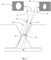
- FIG. 1 A first method according to the invention is illustrated with respect to Figures 2 to 9 .
- the hole 17 has a known/expected form.
- the known/expected form of the hole 17 is generally circular in cross-section but comprises top 32 and bottom 34 tapered/conical sections which narrow to a generally cylindrical bottleneck section 36 toward the middle of the hole.
- the nominal form of the hole is illustrated by the dashed lines, whereas the actual form is illustrated by the solid lines.
- the technique of the invention is to be used to measure a point lying on the interface 38 between the top tapered section 32 of the hole and the generally cylindrical bottleneck section 36 (see Figure 5 ).
- the operator has therefore selected a predetermined point about said interface 38 on a corresponding CAD model of the object 16.
- the nominal location 42 of the predetermined point is shown in Figure 2 .
- the actual location 30 of the predetermined point is different due to the manufacturing tolerances of the object 16.
- the technique can be used to measure a plurality of predetermined points on the object, but for the sake of simplicity of explanation the method will be described for measuring a single point only.
- a backlight 40 is provided to back-illuminate the hole 17.
- the camera probe 20 obtains silhouette images of the hole.
- the camera probe 20 comprises an image sensor 21, e.g. a charge-coupled device (CCD) sensor, on which the hole's silhouette falls.
- CCD charge-coupled device
- the camera probe 20 is illustrated in the Figures using a pin-hole camera model, but as will be understood, the camera probe 20 can comprise one or more lenses (not shown) in order to form an image on the image sensor 21.
- back-lighting is not essential. For example, front-lighting could be used.
- FIG. 3 An example flow-chart for a process 100 according to the invention is shown in Figure 3 .
- the process begins at step 102 with the receipt of an indication of the point to be measured (the "predetermined point").
- the predetermined point could be achieved, for example, by an operator selecting a point on a model (e.g. CAD model) of the object.
- the operator could select the predetermined point by clicking (within a CAD model represented on a graphical user interface on, for example, the host PC 23) on a point on the interface 38 between the top tapered section 32 of the hole and the generally cylindrical bottleneck section 36.
- the operator could select a feature on the CAD model, such as the interface 38 line, and then the computer program could automatically generate one or more points to be inspected based on said selection, e.g. one or more points on the selected feature.
- one or more points to be inspected could be determined/specified by an entirely separate process and received by the current process.
- Step 102 also comprises determining the nominal location 42 of the predetermined point to be measured within the CMM's measurement volume. This is the expected location of the predetermined point to be measured within the CMM's measurement volume. This can be determined based on prior knowledge of the position and orientation of the object 16 as a whole, e.g. from a part set-up/alignment process, and/or from known fixturing for the object 16.
- the nominal position is identified by reference numeral 42.
- the method could merely comprise receiving a nominal point/location within the CMM's measurement volume, wherein the nominal point/location is taken as the expected position of a point on the object to be measured.
- a nominal direction vector N can be associated with the predetermined point.
- Such direction vectors are commonly used in CAD and path planning programs and typically extend normal to the surface of the point to be measured. If the point is at an edge, it can extend normal to either of the surfaces that meet at the edge or direction in between (and the selection of which could depend on what aspect of the part is to be measured). Often such direction vectors are used to dictate the path that a tactile probe takes when moving toward the point to measure it.
- the process 100 then comprises at step 104 obtaining at least two images of the object which are obtained from different perspectives.
- at least first and second images of the object which contain the predetermined point to be measured are obtained from first and second perspectives respectively.
- the position and orientation of the camera 20 for obtaining the first and second images can be determined automatically (e.g. by host PC 23) based on the nominal location 42 of the predetermined point.
- the camera perspectives can be selected so as to put the predetermined point into contrast with the background, e.g. such that the point is one of many points that forms a silhouette.
- the nominal direction vector N can also be used to determine the camera perspectives.
- the position and orientation of the camera 20 for the first and second images are selected so as to ensure that their centres of perspective and the nominal location 42 form a plane that is within a given angle range (e.g. +/-45 ° (degrees)) to the nominal direction vector; ideally (but not necessarily) the centres of perspective 50, 52 and the nominal location 42 form a plane that is parallel to the nominal direction vector N.
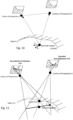
- Figure 4 schematically illustrates the capture of two such images. In particular, first 44 and second 46 silhouette images of the hole are shown.
- first centre of perspective the position of the camera probe's image sensor 21, the position of the camera probe's perspective centre at the time the first image was obtained
- second centre of perspective the position of the camera probe's perspective centre at the time the second image was obtained
- rays illustrating the outer boundaries of the silhouettes are shown.
- Figure 5 illustrates the same configuration of Figure 4 , but in isometric view and without the rays.
- Figure 6 illustrates a plan view of the arrangement shown in Figures 4 and 5 , in which the actual location 30 and the nominal location 42 of the predetermined point, and the first 50 and second 52 centres of perspective are shown.
- the next step 106 of the method of the invention comprises finding the point to be measured in each of the first 44 and second 46 images. This is done based on knowledge of the nominal location 42 and nominal direction vector N of the predetermined point.
- the call-out steps 110 to 116 illustrate one example embodiment of finding the point to be measured in each of the first 44 and second 46 images based on knowledge of the nominal location 42 of the predetermined point.
- the epipolar plane is identified at step 110. This is the plane that is defined by (in particular, contains) the first 50 and second 52 centres of perspective and the nominal location 42.
- the epipolar plane is schematically illustrated in Figure 4 and is identified by reference numeral 56.
- the nominal direction vector N is projected (e.g.
- bounds are then applied to the search vector V, such that it starts and ends at specified search distances before and after the nominal location 42.
- the search distances can be predetermined, e.g. automatically or manually, and are used to limit or "bound" the distance along the vector V relative to the nominal location 42 that the point is to be searched for within the images.
- This bounded search vector V' relative to the nominal location 42 can then be used to establish a bounded search line 60 (which happens to be a bounded epipolar line) in each of the first 44 and second 46 images along which to search for the actual location 30 of the predetermined point.
- the bounded search/epipolar line 60 is determined by projecting the bounded search vector V' into the images (e.g. via perspective projection). If lens distortions are taken into account, the bounded search/epipolar line 60 may not be a straight line. If lens distortions are ignored, or if (for example) the images have been processed to remove distortions (e.g. remove distortions known from camera calibration), then the bounded search/epipolar line 60 can be a straight line.
- vector P itself could be the search vector, rather than having to find its negative V.
- the vector P itself could therefore be projected into the images to define the search/epipolar line 60.
- bounds could be applied to the vector P, to define a bounded vector P' relative to the nominal location, which is then projected (e.g. via perspective projection) into the images to define the bounded search/epipolar line 60.
- a search for a predetermined condition along the bounded epipolar line 60 is performed.
- a search for a transition e.g. a predetermined threshold rate of change in contrast, or other suitable property of the image
- This point 62 is then determined to be the point in the image 44, 46 which corresponds to the actual location 30 of the predetermined point on the object 16. Therefore, at step 108, and as illustrated by Figure 9 , the actual position 30 of the predetermined point within the CMM's measurement volume can be triangulated (e.g. using standard photogrammetry/stereophotogrammetry techniques).
- such triangulation can be performed based on the two-dimensional coordinates of the determined point 62 in each the images 44, 46 and based on the knowledge of the relative location and orientation of the camera probe 20 which took the images (which can be known from the outputs of the CMM's position encoders).
- photogrammetry techniques other than triangulation can be used to determine the actual location 30 of the predetermined point.
- a disparity map and/or bundle adjustment could be used instead of or as well as triangulation.
- an error minimisation technique such as bundle adjustment can be used to simultaneously calculate the positions of multiple points.
- the point to be inspected lay on a circular intersection line.
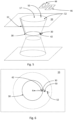
- the invention can be used to find and measure a point on other features, such as an irregularly shaped edge.
- Figures 10 and 11 illustrate such an embodiment.
- the nominal location of the predetermined point to be inspected is identified, and two images of the edge which capture said nominal location are obtained. The centre of perspectives of the two images and the nominal location define an epipolar plane.
- the normal vector N of the point is projected P into the epipolar plane, which defines the search vector V.
- the search vector V is projected into the first and second images to define the bounded search/epipolar lines along which a search is performed to identify the edge.
- the point at which the bounded epipolar line crosses the edge is identified as the predetermined point to be inspected.
- the identified point in each image is then used to measure the location of the predetermined point in the CMM's measurement volume, e.g. via triangulation.
- the change in perspective is achieved by a change in position and orientation of the camera probe.
- a change in perspective could be achieved by a change in position only.
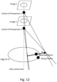
- Figure 12 illustrates a specific example of this, in particular of how the same technique can be used to find a point on a hole, even if the first and second images are obtained from the same camera orientation (angular position) and from positions in which their centre of perspectives both lie on the centre-line of a hole. Accordingly, the perspective can be different by virtue of the image being obtained from a different position, and does not necessary require a change in orientation.
- Such a technique can be particularly useful when inspecting the bottom of a hole (in other words the end of the hole distal to the end at which the probe is positioned).
- the perspective centres don't necessarily both have to lie on the hole's centre-line; one or both could be off the centre-line (e.g. they could be position such that a line containing them is parallel to the centre-line, or even non-parallel).
- the perspective could also be different by virtue of the image being obtained from a different orientation without any change in lateral position of the camera probe (e.g. the rotation not being centred on the perspective centre).
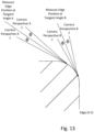
- Figure 13 illustrates how the cross-sectional shape of an edge can be profiled by inspecting different points along its cross-section. As shown, in this embodiment, the images for each point are taken on either side of the tangent to the edge at said point.
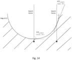
- an optional additional step of the method could be to determine the angle ⁇ between the bounded search/epipolar line and the surface of the object as imaged at the point they intersect. If ⁇ is below a predetermined threshold level, then the determination of the location of the point can be abandoned on the basis that the accuracy will be too low.
- the threshold level can depend on various factors including for example, the required accuracy of the measurement, and the resolution of the images. By way of example only, our inventors have found that for their system, and for their required accuracy, a threshold angle of 45° (degrees) is appropriate.
- Figures 15a to 15c illustrate how the invention can also be used to measure multiple predetermined points 30a, 30b, 30c from the same pair of images.
- the centres of perspectives 50, 52 of the first 44 and second 46 images along with the nominal location 42a, 42b, 42c of each predetermined point can form an epipolar plane 56a, 56b, 56c.
- search vectors can then be formed by projecting (e.g. orthographically) the nominal direction vector for each predetermined point into the respective epipolar plane (56a, 56b, 56c), which can then be projected (e.g.
- first 44 and second 46 images as a bounded epipolar line which can be searched along so as to find the predetermined points in each of the images (which can, if desired, be used so as to triangulate the actual location 30a, 30b, 30c of the predetermined points in the CMM's measurement volume).
- the search line could be determined independently from the nominal direction vector.
- the search line could be determined from the epipolar plane defined by the centre of perspectives of the at least two images and the nominal location (e.g. a line/vector contained within the epipolar plane could be projected into the images). Accordingly, even if there was no nominal direction vector associated with the predetermined point, an operator could manually choose the centre of perspective for each image (ideally, but not necessarily, which put them in positions such that they, along with the nominal location, define an epipolar plane that is substantially normal to the surface at the predetermined point), and then the method of the invention can determine the search line based on the epipolar lines for said images.
- the above embodiments comprise obtaining two images and finding the predetermined point in each of the images.
- the invention could be used to find the point in a greater number of images.
- the invention can be used to find a predetermined point in just one image. This is the case even if just one image is obtained (or used).
- a search line in the image could be derived (e.g. by projecting a predetermined search vector/nominal direction vector associated with the point, into the image), and the predetermined point can be determined as being where the search line intersects the surface as imaged (e.g. where a threshold rate of change in a property of the image is met).
- Such a process could comprise ambiguity of the actual location of the predetermined point in the Z direction (i.e. perpendicular to the image plane). Accordingly, either the position in Z could be assumed or determined/deduced from another measurement of the artefact (e.g. a tactile measurement of where at least a part of the artefact is in Z).
- the point could lie on a marker placed or projected onto the object.
- a bright line could be projected on the object, and it might be desirable to measure the location of a given point on the line.
- the method of the invention can be used, e.g. by using the same technique but in which in the images it is determined where the bounded epipolar line crosses the imaged bright line.
- the nominal point(s) could be picked from the expected edge of the bright line on the part (using CAD) while the associated direction vector(s) would ideally (but not necessarily) be normal to the bright line, typically between tangent and normal to the surface.
- centres of perspective of the images could be chosen such the epipolar plane they, along with the nominal location, define intersect with the bright line at an angle complying with the above described requirements (e.g. at an angle not less than 45 degrees, and preferably at an angle that is substantially perpendicular).
- the point could lie on a surface feature.
- the surface feature could be printed or texture.
- the surface feature could be known or unknown and potentially random.
- the nominal point could be picked from an expected edge and where the surface feature is unknown or random, the nominal point could be chosen where a surface feature edge is expected.
- the associated nominal direction vector(s) should ideally (but not necessarily) be normal to the expected edge and parallel to the surface.
- the search distance(s) (which define the bounds on the search line) can be chosen to be less than the expected repeat distance of the surface feature.
- a search along the search line for a predetermined change in the image can be performed to determine where the search line crosses the feature (and thereby define the location of the point to be found).
- the point is a single point on the object.
- the point could define the location of an aspect, feature, or pattern for example.
- the point could define the position of a corner feature of the object.
- the point could define the position of a pixel-signature (e.g. a map of grey-scale values) of a group of pixels.
- multiple points measured via the method of the invention can be considered together to describe an aspect/feature of the object.
- multiple points could be taken along an edge, which together describe the shape, position and/or size of the edge.
- multiple points could be taken around the top or bottom of a hole, or even an edge/lip located within a hole, and together they can be used to describe the shape/position/size of the edge, e.g. for finding the diameter of the hole.
- Multiple points can also be grouped/considered together to describe the three-dimensional form of a surface.
- the method can comprise fitting multiple points to a feature (or a feature to multiple points), e.g.
- a regular or irregular shape such as a line (straight or not straight), circle, or even three-dimensional shapes, e.g. cylinders or non-regular three-dimensional shapes.
- a mesh-model could be fitted to the points.
- the images obtained by the camera probe 20 are passed to the host PC 23 which is configured with software for processing the images to find the predetermined point in each of the images and then to determine the actual location of the predetermined point within the CMM's 10 measurement volume.
- the host PC 23 is configured with software for processing the images to find the predetermined point in each of the images and then to determine the actual location of the predetermined point within the CMM's 10 measurement volume.
- a separate (e.g. bespoke) processor/analyser device could be provided which is configured to process the images in accordance with the invention.
- multiple processor/analyser devices could be used. For example, one for analysing the images to identify the predetermined point within the images and another for then determining the actual location of the predetermined point within CMM's measurement volume.
- the controller 22 could perform at least some of the processing of the images to determine the actual location of the predetermined point.
Applications Claiming Priority (2)
| Application Number | Priority Date | Filing Date | Title |
|---|---|---|---|
| EP15275170 | 2015-07-13 | ||
| PCT/GB2016/052079 WO2017009615A1 (en) | 2015-07-13 | 2016-07-11 | Method for measuring an artefact |
Publications (2)
| Publication Number | Publication Date |
|---|---|
| EP3322959A1 EP3322959A1 (en) | 2018-05-23 |
| EP3322959B1 true EP3322959B1 (en) | 2024-04-03 |
Family
ID=53762093
Family Applications (1)
| Application Number | Title | Priority Date | Filing Date |
|---|---|---|---|
| EP16738530.1A Active EP3322959B1 (en) | 2015-07-13 | 2016-07-11 | Method for measuring an artefact |
Country Status (5)
| Country | Link |
|---|---|
| US (1) | US10591289B2 (zh) |
| EP (1) | EP3322959B1 (zh) |
| JP (2) | JP7353757B2 (zh) |
| CN (1) | CN107850425B (zh) |
| WO (1) | WO2017009615A1 (zh) |
Families Citing this family (5)
| Publication number | Priority date | Publication date | Assignee | Title |
|---|---|---|---|---|
| EP3345723A1 (de) * | 2017-01-10 | 2018-07-11 | Ivoclar Vivadent AG | Verfahren zur steuerung einer werkzeugmaschine |
| DE102017219407A1 (de) * | 2017-10-27 | 2019-05-02 | Robert Bosch Gmbh | Erfassungsvorrichtung |
| EP3486606A1 (de) * | 2017-11-20 | 2019-05-22 | Leica Geosystems AG | Stereokamera und stereophotogrammetrisches verfahren |
| DE102018213142A1 (de) * | 2018-08-06 | 2020-02-06 | Carl Zeiss Industrielle Messtechnik Gmbh | Anordnung und Verfahren zum Erfassen einer an einem Objekt angeordneten Markeranordnung |
| EP4282582A1 (fr) * | 2022-05-25 | 2023-11-29 | Universo S.A. | Procédé de détermination de la position d'une pièce dans un repère orthonormé basé sur une structure d'une machine-outil à commande numérique |
Citations (3)
| Publication number | Priority date | Publication date | Assignee | Title |
|---|---|---|---|---|
| JPH09184712A (ja) * | 1995-12-28 | 1997-07-15 | Ishikawajima Harima Heavy Ind Co Ltd | 3次元構造物の形状検査方法 |
| EP1521212A2 (en) * | 2003-10-03 | 2005-04-06 | General Electric Company | Surface reconstruction and registration with a Helmholtz reciprocal image pair |
| US20110264402A1 (en) * | 2007-08-20 | 2011-10-27 | Renishaw Plc | Course of motion determination |
Family Cites Families (31)
| Publication number | Priority date | Publication date | Assignee | Title |
|---|---|---|---|---|
| EP0070017B1 (en) * | 1981-07-14 | 1986-10-29 | Hitachi, Ltd. | Pattern detection system |
| US5251156A (en) | 1990-08-25 | 1993-10-05 | Carl-Zeiss-Stiftung, Heidenheim/Brenz | Method and apparatus for non-contact measurement of object surfaces |
| JP2971822B2 (ja) * | 1996-11-06 | 1999-11-08 | 株式会社ミツトヨ | 非接触画像計測システム |
| WO2000037884A1 (fr) * | 1998-12-22 | 2000-06-29 | Mitsubishi Denki Kabushiki Kaisha | Procede et appareil permettant de mesurer des erreurs de positionnement au moyen d'un repere, et appareil d'usinage susceptible de corriger des erreurs en fonction de resultats de mesure |
| US6615072B1 (en) * | 1999-02-04 | 2003-09-02 | Olympus Optical Co., Ltd. | Optical imaging device |
| SE516239C2 (sv) * | 2000-04-28 | 2001-12-03 | Mydata Automation Ab | Metod och anordning för bestämning av nominella data för elektroniska kretsar, genom att ta en digital bild och jämföra med lagrade nominella data. |
| TWI234658B (en) * | 2000-11-02 | 2005-06-21 | Tb Optical Co Ltd | Photosensor device and disk inspection apparatus using it |
| US6831738B2 (en) * | 2001-06-26 | 2004-12-14 | Adc Telecommunications, Inc. | Method and apparatus for inspecting end surfaces on optical connectors |
| US20030026567A1 (en) * | 2001-08-01 | 2003-02-06 | Schott Communications Technologies, Inc. | Graded index fiber, array and method of manufacture |
| US6954262B2 (en) * | 2002-03-18 | 2005-10-11 | Mike Buzzetti | Automated fiber optic inspection system |
| US6989895B2 (en) * | 2002-03-18 | 2006-01-24 | Mike Buzzetti | Automated fiber optic inspection system |
| JP3922085B2 (ja) * | 2002-04-25 | 2007-05-30 | ヤマハ株式会社 | 光ファイバ束の保持構造 |
| US6963062B2 (en) * | 2003-04-07 | 2005-11-08 | Eksigent Technologies, Llc | Method for multiplexed optical detection including a multimode optical fiber in which propagation modes are coupled |
| CA2522097C (en) * | 2003-04-28 | 2012-09-25 | Stephen James Crampton | Cmm arm with exoskeleton |
| FI117086B (fi) * | 2004-03-12 | 2006-06-15 | Aker Finnyards Oy | Menetelmä ja järjestely profiiliaihioiden työstämiseksi |
| GB0508395D0 (en) * | 2005-04-26 | 2005-06-01 | Renishaw Plc | Method for scanning the surface of a workpiece |
| US7773797B2 (en) | 2006-02-06 | 2010-08-10 | Beijing University Of Aeronautics And Astronautics | Methods and apparatus for measuring the flapping deformation of insect wings |
| DE102007008598A1 (de) | 2007-02-19 | 2008-08-21 | Fraunhofer-Gesellschaft zur Förderung der angewandten Forschung e.V. | Automatische Programmierung von Robotern zum Abschweißen gehefteter Profile auf Mikropaneelen mit Hilfe digitaler Bilderfassung |
| US7673551B2 (en) * | 2007-08-15 | 2010-03-09 | Heinrich Meurer | Aerial-supported procedure for the detection of landmines |
| WO2009024757A1 (en) * | 2007-08-17 | 2009-02-26 | Renishaw Plc | Phase analysis measurement apparatus and method |
| EP2112465A1 (en) * | 2008-04-24 | 2009-10-28 | Snap-on Equipment Srl a unico socio. | Parameter detection system for wheels |
| JP5271031B2 (ja) * | 2008-08-09 | 2013-08-21 | 株式会社キーエンス | 画像のデータ圧縮方法、画像処理におけるパターンモデルの位置決め方法、画像処理装置、画像処理プログラム及びコンピュータで読み取り可能な記録媒体 |
| GB0909635D0 (en) * | 2009-06-04 | 2009-07-22 | Renishaw Plc | Vision measurement probe |
| CN101672637B (zh) * | 2009-09-24 | 2012-08-15 | 华东理工大学 | 一种复杂曲面的数字化检测方法 |
| JP2012068062A (ja) * | 2010-09-21 | 2012-04-05 | Fuji Xerox Co Ltd | 位置合わせ装置、位置合わせシステム及び位置合わせプログラム |
| US9230339B2 (en) | 2013-01-07 | 2016-01-05 | Wexenergy Innovations Llc | System and method of measuring distances related to an object |
| JP6150532B2 (ja) * | 2013-01-22 | 2017-06-21 | オリンパス株式会社 | 計測装置およびプログラム |
| CN104567812A (zh) * | 2013-10-12 | 2015-04-29 | 北京航天计量测试技术研究所 | 空间位置测量方法及装置 |
| WO2015085982A1 (de) * | 2013-12-11 | 2015-06-18 | Api International Ag | Vorrichtung zur 3-d-vermessung einer oberfläche und projektionseinheit, sowie verfahren zur 3-d-vermessung |
| CN106170678A (zh) | 2014-02-24 | 2016-11-30 | 瑞尼斯豪公司 | 利用视觉探针检测物体的方法 |
| KR102082302B1 (ko) * | 2014-09-02 | 2020-02-27 | 삼성전자주식회사 | 엑스선 검출 장치 및 엑스선 장치 |
-
2016
- 2016-07-11 JP JP2018501266A patent/JP7353757B2/ja active Active
- 2016-07-11 EP EP16738530.1A patent/EP3322959B1/en active Active
- 2016-07-11 US US15/577,191 patent/US10591289B2/en active Active
- 2016-07-11 CN CN201680041034.2A patent/CN107850425B/zh active Active
- 2016-07-11 WO PCT/GB2016/052079 patent/WO2017009615A1/en active Application Filing
-
2021
- 2021-10-01 JP JP2021162978A patent/JP2021193400A/ja active Pending
Patent Citations (3)
| Publication number | Priority date | Publication date | Assignee | Title |
|---|---|---|---|---|
| JPH09184712A (ja) * | 1995-12-28 | 1997-07-15 | Ishikawajima Harima Heavy Ind Co Ltd | 3次元構造物の形状検査方法 |
| EP1521212A2 (en) * | 2003-10-03 | 2005-04-06 | General Electric Company | Surface reconstruction and registration with a Helmholtz reciprocal image pair |
| US20110264402A1 (en) * | 2007-08-20 | 2011-10-27 | Renishaw Plc | Course of motion determination |
Also Published As
| Publication number | Publication date |
|---|---|
| JP2018522240A (ja) | 2018-08-09 |
| WO2017009615A1 (en) | 2017-01-19 |
| EP3322959A1 (en) | 2018-05-23 |
| US10591289B2 (en) | 2020-03-17 |
| CN107850425B (zh) | 2022-08-26 |
| JP2021193400A (ja) | 2021-12-23 |
| CN107850425A (zh) | 2018-03-27 |
| JP7353757B2 (ja) | 2023-10-02 |
| US20180156608A1 (en) | 2018-06-07 |
Similar Documents
| Publication | Publication Date | Title |
|---|---|---|
| US20170160077A1 (en) | Method of inspecting an object with a vision probe | |
| US11563931B2 (en) | System and method for calibrating a vision system with respect to a touch probe | |
| EP3322959B1 (en) | Method for measuring an artefact | |
| JP6280525B2 (ja) | カメラのミスキャリブレーションの実行時決定のためのシステムと方法 | |
| JP5943547B2 (ja) | 非接触測定を行う装置および方法 | |
| US8917942B2 (en) | Information processing apparatus, information processing method, and program | |
| CN112161619B (zh) | 位姿检测方法、三维扫描路径规划方法和检测系统 | |
| JP2009511881A (ja) | 実用的な3dビジョンシステムの方法および装置 | |
| Bernal et al. | Performance evaluation of optical scanner based on blue LED structured light | |
| EP3491333B1 (en) | Non-contact probe and method of operation | |
| GB2520711A (en) | Calibration apparatus and method for computed tomography | |
| JP2017033429A (ja) | 3次元物体検査装置 | |
| US10670390B2 (en) | System and method for verifying projection accuracy | |
| Tai et al. | Noncontact profilometric measurement of large-form parts | |
| JP2015007639A (ja) | 情報処理装置、情報処理方法およびプログラム | |
| US20190113336A1 (en) | Multi-Directional Triangulation Measuring System with Method | |
| Bauer et al. | Accuracy Analysis of Alignment Methods based on Reference Features for Robot-Based Optical Inspection Systems | |
| JP7476814B2 (ja) | 検査装置 | |
| KR102434419B1 (ko) | 다점 마커 및 스테레오 비전을 이용한 정밀 3d 스캔 장치 및 방법 | |
| Barone et al. | Optical tactile probe for the inspection of mechanical components | |
| Meng et al. | An angle measurement system for bending machine based on binocular active vision | |
| JP2015052490A (ja) | 形状測定装置、構造物製造システム、形状測定方法、構造物製造方法、及び形状測定プログラム | |
| Li et al. | Simultaneous sensor and hand-sensor calibration of a robot-based measurement system |
Legal Events
| Date | Code | Title | Description |
|---|---|---|---|
| STAA | Information on the status of an ep patent application or granted ep patent |
Free format text: STATUS: THE INTERNATIONAL PUBLICATION HAS BEEN MADE |
|
| PUAI | Public reference made under article 153(3) epc to a published international application that has entered the european phase |
Free format text: ORIGINAL CODE: 0009012 |
|
| STAA | Information on the status of an ep patent application or granted ep patent |
Free format text: STATUS: REQUEST FOR EXAMINATION WAS MADE |
|
| 17P | Request for examination filed |
Effective date: 20180131 |
|
| AK | Designated contracting states |
Kind code of ref document: A1 Designated state(s): AL AT BE BG CH CY CZ DE DK EE ES FI FR GB GR HR HU IE IS IT LI LT LU LV MC MK MT NL NO PL PT RO RS SE SI SK SM TR |
|
| AX | Request for extension of the european patent |
Extension state: BA ME |
|
| DAV | Request for validation of the european patent (deleted) | ||
| DAX | Request for extension of the european patent (deleted) | ||
| STAA | Information on the status of an ep patent application or granted ep patent |
Free format text: STATUS: EXAMINATION IS IN PROGRESS |
|
| 17Q | First examination report despatched |
Effective date: 20191025 |
|
| STAA | Information on the status of an ep patent application or granted ep patent |
Free format text: STATUS: EXAMINATION IS IN PROGRESS |
|
| STAA | Information on the status of an ep patent application or granted ep patent |
Free format text: STATUS: EXAMINATION IS IN PROGRESS |
|
| REG | Reference to a national code |
Ref country code: DE Ref legal event code: R079 Ref document number: 602016086658 Country of ref document: DE Free format text: PREVIOUS MAIN CLASS: G01B0021040000 Ipc: G06T0007500000 Ref country code: DE Ref legal event code: R079 Free format text: PREVIOUS MAIN CLASS: G01B0021040000 Ipc: G06T0007500000 |
|
| GRAP | Despatch of communication of intention to grant a patent |
Free format text: ORIGINAL CODE: EPIDOSNIGR1 |
|
| STAA | Information on the status of an ep patent application or granted ep patent |
Free format text: STATUS: GRANT OF PATENT IS INTENDED |
|
| RIC1 | Information provided on ipc code assigned before grant |
Ipc: G01B 11/00 20060101ALI20231106BHEP Ipc: G01B 11/24 20060101ALI20231106BHEP Ipc: G06T 7/50 20170101AFI20231106BHEP |
|
| INTG | Intention to grant announced |
Effective date: 20231124 |
|
| GRAS | Grant fee paid |
Free format text: ORIGINAL CODE: EPIDOSNIGR3 |
|
| GRAA | (expected) grant |
Free format text: ORIGINAL CODE: 0009210 |
|
| STAA | Information on the status of an ep patent application or granted ep patent |
Free format text: STATUS: THE PATENT HAS BEEN GRANTED |
|
| AK | Designated contracting states |
Kind code of ref document: B1 Designated state(s): AL AT BE BG CH CY CZ DE DK EE ES FI FR GB GR HR HU IE IS IT LI LT LU LV MC MK MT NL NO PL PT RO RS SE SI SK SM TR |
|
| REG | Reference to a national code |
Ref country code: GB Ref legal event code: FG4D |
|
| REG | Reference to a national code |
Ref country code: CH Ref legal event code: EP |
|
| REG | Reference to a national code |
Ref country code: DE Ref legal event code: R096 Ref document number: 602016086658 Country of ref document: DE |