EP3322380B1 - Selbstexpandierende herzunterstützungsvorrichtung - Google Patents
Selbstexpandierende herzunterstützungsvorrichtung Download PDFInfo
- Publication number
- EP3322380B1 EP3322380B1 EP16825268.2A EP16825268A EP3322380B1 EP 3322380 B1 EP3322380 B1 EP 3322380B1 EP 16825268 A EP16825268 A EP 16825268A EP 3322380 B1 EP3322380 B1 EP 3322380B1
- Authority
- EP
- European Patent Office
- Prior art keywords
- self
- midway
- expanding
- bends
- framework
- Prior art date
- Legal status (The legal status is an assumption and is not a legal conclusion. Google has not performed a legal analysis and makes no representation as to the accuracy of the status listed.)
- Active
Links
Images


Classifications
-
- A—HUMAN NECESSITIES
- A61—MEDICAL OR VETERINARY SCIENCE; HYGIENE
- A61F—FILTERS IMPLANTABLE INTO BLOOD VESSELS; PROSTHESES; DEVICES PROVIDING PATENCY TO, OR PREVENTING COLLAPSING OF, TUBULAR STRUCTURES OF THE BODY, e.g. STENTS; ORTHOPAEDIC, NURSING OR CONTRACEPTIVE DEVICES; FOMENTATION; TREATMENT OR PROTECTION OF EYES OR EARS; BANDAGES, DRESSINGS OR ABSORBENT PADS; FIRST-AID KITS
- A61F2/00—Filters implantable into blood vessels; Prostheses, i.e. artificial substitutes or replacements for parts of the body; Appliances for connecting them with the body; Devices providing patency to, or preventing collapsing of, tubular structures of the body, e.g. stents
- A61F2/02—Prostheses implantable into the body
- A61F2/24—Heart valves ; Vascular valves, e.g. venous valves; Heart implants, e.g. passive devices for improving the function of the native valve or the heart muscle; Transmyocardial revascularisation [TMR] devices; Valves implantable in the body
- A61F2/2478—Passive devices for improving the function of the heart muscle, i.e. devices for reshaping the external surface of the heart, e.g. bags, strips or bands
- A61F2/2481—Devices outside the heart wall, e.g. bags, strips or bands
-
- A—HUMAN NECESSITIES
- A61—MEDICAL OR VETERINARY SCIENCE; HYGIENE
- A61M—DEVICES FOR INTRODUCING MEDIA INTO, OR ONTO, THE BODY; DEVICES FOR TRANSDUCING BODY MEDIA OR FOR TAKING MEDIA FROM THE BODY; DEVICES FOR PRODUCING OR ENDING SLEEP OR STUPOR
- A61M60/00—Blood pumps; Devices for mechanical circulatory actuation; Balloon pumps for circulatory assistance
- A61M60/10—Location thereof with respect to the patient's body
- A61M60/122—Implantable pumps or pumping devices, i.e. the blood being pumped inside the patient's body
- A61M60/165—Implantable pumps or pumping devices, i.e. the blood being pumped inside the patient's body implantable in, on, or around the heart
- A61M60/191—Implantable pumps or pumping devices, i.e. the blood being pumped inside the patient's body implantable in, on, or around the heart mechanically acting upon the outside of the patient's native heart, e.g. compressive structures placed around the heart
-
- A—HUMAN NECESSITIES
- A61—MEDICAL OR VETERINARY SCIENCE; HYGIENE
- A61M—DEVICES FOR INTRODUCING MEDIA INTO, OR ONTO, THE BODY; DEVICES FOR TRANSDUCING BODY MEDIA OR FOR TAKING MEDIA FROM THE BODY; DEVICES FOR PRODUCING OR ENDING SLEEP OR STUPOR
- A61M60/00—Blood pumps; Devices for mechanical circulatory actuation; Balloon pumps for circulatory assistance
- A61M60/20—Type thereof
- A61M60/289—Devices for mechanical circulatory actuation assisting the residual heart function by means mechanically acting upon the patient's native heart or blood vessel structure, e.g. direct cardiac compression [DCC] devices
-
- A—HUMAN NECESSITIES
- A61—MEDICAL OR VETERINARY SCIENCE; HYGIENE
- A61M—DEVICES FOR INTRODUCING MEDIA INTO, OR ONTO, THE BODY; DEVICES FOR TRANSDUCING BODY MEDIA OR FOR TAKING MEDIA FROM THE BODY; DEVICES FOR PRODUCING OR ENDING SLEEP OR STUPOR
- A61M60/00—Blood pumps; Devices for mechanical circulatory actuation; Balloon pumps for circulatory assistance
- A61M60/40—Details relating to driving
- A61M60/465—Details relating to driving for devices for mechanical circulatory actuation
- A61M60/468—Details relating to driving for devices for mechanical circulatory actuation the force acting on the actuation means being hydraulic or pneumatic
-
- A—HUMAN NECESSITIES
- A61—MEDICAL OR VETERINARY SCIENCE; HYGIENE
- A61M—DEVICES FOR INTRODUCING MEDIA INTO, OR ONTO, THE BODY; DEVICES FOR TRANSDUCING BODY MEDIA OR FOR TAKING MEDIA FROM THE BODY; DEVICES FOR PRODUCING OR ENDING SLEEP OR STUPOR
- A61M60/00—Blood pumps; Devices for mechanical circulatory actuation; Balloon pumps for circulatory assistance
- A61M60/80—Constructional details other than related to driving
- A61M60/839—Constructional details other than related to driving of devices for mechanical circulatory actuation
-
- A—HUMAN NECESSITIES
- A61—MEDICAL OR VETERINARY SCIENCE; HYGIENE
- A61M—DEVICES FOR INTRODUCING MEDIA INTO, OR ONTO, THE BODY; DEVICES FOR TRANSDUCING BODY MEDIA OR FOR TAKING MEDIA FROM THE BODY; DEVICES FOR PRODUCING OR ENDING SLEEP OR STUPOR
- A61M60/00—Blood pumps; Devices for mechanical circulatory actuation; Balloon pumps for circulatory assistance
- A61M60/80—Constructional details other than related to driving
- A61M60/855—Constructional details other than related to driving of implantable pumps or pumping devices
- A61M60/865—Devices for guiding or inserting pumps or pumping devices into the patient's body
-
- A—HUMAN NECESSITIES
- A61—MEDICAL OR VETERINARY SCIENCE; HYGIENE
- A61F—FILTERS IMPLANTABLE INTO BLOOD VESSELS; PROSTHESES; DEVICES PROVIDING PATENCY TO, OR PREVENTING COLLAPSING OF, TUBULAR STRUCTURES OF THE BODY, e.g. STENTS; ORTHOPAEDIC, NURSING OR CONTRACEPTIVE DEVICES; FOMENTATION; TREATMENT OR PROTECTION OF EYES OR EARS; BANDAGES, DRESSINGS OR ABSORBENT PADS; FIRST-AID KITS
- A61F2/00—Filters implantable into blood vessels; Prostheses, i.e. artificial substitutes or replacements for parts of the body; Appliances for connecting them with the body; Devices providing patency to, or preventing collapsing of, tubular structures of the body, e.g. stents
- A61F2/02—Prostheses implantable into the body
- A61F2/24—Heart valves ; Vascular valves, e.g. venous valves; Heart implants, e.g. passive devices for improving the function of the native valve or the heart muscle; Transmyocardial revascularisation [TMR] devices; Valves implantable in the body
- A61F2/2478—Passive devices for improving the function of the heart muscle, i.e. devices for reshaping the external surface of the heart, e.g. bags, strips or bands
- A61F2/2481—Devices outside the heart wall, e.g. bags, strips or bands
- A61F2002/2484—Delivery devices therefor
Definitions
- the present invention relates in general to the field of heart assist devices, and more particularly, to a device for minimally invasive delivery of extra-cardiac devices.
- a sternotomy is the preferred method of implantation of the cardiac compression device.
- Sternotomy is a type of surgical procedure in which a vertical inline incision is made along the sternum, after which the sternum itself is divided, or "cracked". This procedure provides access to the heart for surgical procedures.
- Conventional direct cardiac compression devices such as the Anstadt cup, require a sternotomy for implantation, which is a very painful procedure.
- sternotomies result in long recovery times and a high risk of infection. Further, there is a high risk of complications due to the lengthy surgery required for these unstable patients.
- US 2013/102849 A1 discloses a device that is supposed to aid in the positioning of a direct cardiac compression device about the heart.
- the compression device comprises wire loops having curved surfaces.
- US 2010/081867 A1 concerns an apparatus for delivering a medical device onto a heart.
- the medical device includes a deflector.
- the deflector can comprise a number of wire form petals.
- US 2011/257461 A1 concerns a ventricular function assisting device configured to be implanted in heart ventricle.
- the present inventors recognized a need for minimally invasive devices to be deployed without the help of guidewires.
- the present invention reduces the risk of guidewire entanglement to the patient.
- the present invention provides a self-expanding wire framework device according to claim 1. More specific embodiments are defined by the dependent claims.
- the self-expanding wire framework device comprises: a deployment tube and a self-expanding wire framework positioned inside the deployment tube and covered with a polymer film adapted to flare outwardly to encircle a portion of the heart, wherein the self-expanding wire framework comprises: a set of adjacent articulated wire loops extending from a lead edge to a hub, wherein each of the articulated wire loops of the set of articulated wire loops comprise a top segment positioned at the lead edge and that extends to a left midway bend and to a right midway bend, a left strut that extends from the left midway bend to the hub, a right strut that extends from the right midway bend to the hub, and a fixed strut attachment point on the hub to fix the position of the left strut and the right strut, wherein each of the articulated wire loops of the set of articulated wire loops is positioned to at least partially overlap an adjacent articulated wire loop, and wherein the left midway bend
- the left midway bends and the right midway bends may be rounded to allow for gradual flaring as the self-expanding wire framework is deployed.
- the left midway bends and the right midway bends may be flattened to allow for flaring as the self-expanding wire framework is deployed.
- the left midway bends and the right midway bends may further comprise multiple bends to allow for immediate flaring positions as the self-expanding wire framework is deployed.
- the articulated wire loops may be a non-rounded wire.
- the set of articulated wire loops may comprises at least 2, 3, 4, 5, 6, 7, 8, 9, 10, 11, 12, 13, 14, 15, 16, 17, 18, 19, 20 or more articulated wire loops.
- the left strut may be connected to the right strut between the midway bend and the hub.
- the left strut may be intertwined with the right strut between the midway bend and the hub.
- the left strut and the right strut may be connected separately at the hub.
- Each of the articulated wire loops of the set of articulated wire loops may be positioned adjacent to an adjacent articulated wire loop.
- Each of the articulated wire loops of the set of articulated wire loops is positioned to at least partially overlap the adjacent articulated wire loop.
- the polymer film may be on the inside of the self-expanding wire framework.
- the polymer film may be on the outside of the self-expanding wire framework.
- the polymer film may be on the inside and the outside to sandwich the self-expanding wire framework.
- the left strut and the right strut each may comprise a bend end connected to the midway bend and a hub end, wherein the hub end is secured to the hub at a fixed strut attachment point.
- the device may further comprising a deployment tube having an outer surface surrounding an inner passage and a deployment aperture at one end of the inner passage, wherein the self-expanding wire framework covered with a polymer film is slidably positioned in the inner passage to slidably extend from the deployment aperture and adapted to flare outwardly to encircle a larger portion of the heart.
- the self-expanding wire framework is positioned inside the deployment tube and the top segments are bent, and the left midway bends and the right midway bends are straightened.
- the present invention provides a self-expanding framework device adapted to facilitate the deployment of an extra-cardiac device, comprising: a deployment tube having an outer surface surrounding an inner passage and a deployment aperture at one end of the inner passage, and a self-expanding wire framework covered with a polymer film and slidably positioned in the inner passage to slidably extend from the deployment aperture and adapted to flare outwardly to encircle a larger portion of the heart, wherein the self-expanding wire framework comprises: a set of articulated wire loops extending from a lead edge to a hub, wherein each of the articulated wire loops of the set of articulated wire loops comprise a top segment positioned at the lead edge and that extends to a left midway bend and to a right midway bend, a left strut that extends from the left midway bend to the hub, a right strut that extends from the right midway bend to the hub, and a fixed strut attachment point on the hub to fix the
- the self-expanding wire framework is positioned inside the deployment tube with the top segments bent such that the left midway bends and the right midway bends are relatively straightened.
- the left midway bends and the right midway bends are rounded to allow for gradual flaring as the self-expanding wire framework is deployed from the deployment tube.
- the left midway bends and the right midway bends are flattened to allow for flaring as the self-expanding wire framework is deployed from the deployment tube.
- the left midway bends and the right midway bends further comprise multiple bends to allow for immediate flaring positions as the self-expanding wire framework is deployed from the deployment tube.
- the articulated wire loops may be a non-rounded wire.
- the set of articulated wire loops may comprises at least 2, 3, 4, 5, 6, 7, 8, 9, 10, 11, 12, 13, 14, 15, 16, 17, 18, 19, 20 or more articulated wire loops.
- the left strut may be connected to the right strut between the midway bend and the hub.
- the left strut may be intertwined with the right strut between the midway bend and the hub.
- the left strut and the right strut may be connected separately at the hub.
- Each of the articulated wire loops of the set of articulated wire loops may be positioned adjacent to an adjacent articulated wire loop.
- Each of the articulated wire loops of the set of articulated wire loops is positioned to at least partially overlap the adjacent articulated wire loop.
- the polymer film may be on the inside of the self-expanding wire framework.
- the polymer film may be on the outside of the self-expanding wire framework.
- the polymer film may be on the inside and the outside to sandwich the self-expanding wire framework.
- the left strut and the right strut each may comprise a bend end connected to the midway bend and a hub end, wherein the hub end is secured to the hub at a fixed strut attachment point.
- the device may further comprising a deployment tube having an outer surface surrounding an inner passage and a deployment aperture at one end of the inner passage, wherein the self-expanding wire framework covered with a polymer film is slidably positioned in the inner passage to slidably extend from the deployment aperture and adapted to flare outwardly to encircle a larger portion of the heart.
- the self-expanding wire framework is positioned inside the deployment tube and the top segments are bent, and the left midway bends and the right midway bends are straightened.
- the present invention provides a self-expanding wire framework device comprising: a self-expanding wire framework covered with a polymer film.
- the polymer film may be a passive covering for the purposes of a passive device for diastolic heart failure.
- the passive covering may include one or more fluid chambers that are passively filled with fluid to compress the heart.
- the passive covering may include a port to adjust the volume of fluid in the passive chambers as desired.
- the polymer film may include active inflation chambers to assist the heart.
- the device comprising a polymer film adapted to fit about the heart, wherein the polymer film is in contact with the heart; an outer film in contact with the biocompatible inner film; one or more fluid chambers formed between the biocompatible inner film and the outer film; and a fluid connection in fluid communication with the one or more fluid chambers, wherein a fluid enters the one or more fluid chambers through the fluid connection to selectively compress the heart during a heart contraction and during recoil the fluid exits the one or more fluid chambers through the fluid connection to allow the heart to decompress.
- the device may further comprise a pneumatic driver operably linked to the fluid connection to pressurize the biocompatible inner membrane to compress the heart and depressurize the biocompatible inner membrane to aid in filling the heart.
- the polymer film comprises a biocompatible inner film pneumatically locked to the heart to allow the inner film to pull open the heart and aid in filling of the heart.
- the polymer film may include both an active set of chambers and a passive set of chambers.
- the device comprising an inner polymer film comprising one or more passive chambers adapted to fit about the heart.
- Each of the one or more passive chambers may be individually filled with a fixed volume of fluid. This fixed volume of fluid may be varied through a port to change the size of the one or more passive chambers and thus the fitment of the device about the heart.
- the device also includes an outer film in contact with the inner film; one or more fluid chambers formed between the inner film and the outer film; and a fluid connection in fluid communication with the one or more fluid chambers, wherein a fluid enters the one or more fluid chambers through the fluid connection to selectively compress the heart during a heart contraction and during recoil the fluid exits the one or more fluid chambers through the fluid connection to allow the heart to decompress.
- the device may further comprise a pneumatic driver operably linked to the fluid connection to pressurize the biocompatible inner membrane to compress the heart and depressurize the biocompatible inner membrane to aid in filling the heart.
- the polymer film comprises a biocompatible inner film pneumatically locked to the heart to allow the inner film to expand the heart and aid in filling of the heart.
- the present disclosure provides a method for implanting DCCD device about the heart using a self-expanding framework delivery device, comprising the steps of: providing a self-expanding framework delivery device comprising a deployment tube having an outer surface surrounding an inner passage and a deployment aperture at one end of the inner passage, and a self-expanding wire framework covered with a polymer film and slidably positioned in the inner passage to slidably extend from the deployment aperture and adapted to flare outwardly to encircle a larger portion of the heart, wherein the self-expanding wire framework comprises: a set of articulated wire loops extending from a lead edge to a hub, wherein each of the articulated wire loops of the set of articulated wire loops comprise a top segment positioned at the lead edge and that extends to a left midway bend and to a right midway bend, a left strut that extends from the left midway bend to the hub, a right strut that extends from the right midway bend to the
- the left midway bends and the right midway bends may be rounded to allow for gradual flaring as the self-expanding wire framework is deployed.
- the left midway bends and the right midway bends may be flattened to allow for flaring as the self-expanding wire framework is deployed.
- the left midway bends and the right midway bends may further comprise multiple bends to allow for immediate flaring positions as the self-expanding wire framework is deployed.
- the articulated wire loops may be a non-rounded wire.
- the set of articulated wire loops may comprises at least 2, 3, 4, 5, 6, 7, 8, 9, 10, 11, 12, 13, 14, 15, 16, 17, 18, 19, 20 or more articulated wire loops.
- the left strut may be connected to the right strut between the midway bend and the hub.
- the left strut may be intertwined with the right strut between the midway bend and the hub.
- the left strut and the right strut may be connected separately at the hub.
- Each of the articulated wire loops of the set of articulated wire loops may be positioned adjacent to an adjacent articulated wire loop.
- Each of the articulated wire loops of the set of articulated wire loops is positioned to at least partially overlap the adjacent articulated wire loop.
- the polymer film may be on the inside of the self-expanding wire framework.
- the polymer film may be on the outside of the self-expanding wire framework.
- the polymer film may be on the inside and the outside to sandwich the self-expanding wire framework.
- the left strut and the right strut each may comprise a bend end connected to the midway bend and a hub end, wherein the hub end is secured to the hub at a fixed strut attachment point.
- the device may further comprise a deployment tube having an outer surface surrounding an inner passage and a deployment aperture at one end of the inner passage, wherein the self-expanding wire framework covered with a polymer film is slidably positioned in the inner passage to slidably extend from the deployment aperture and adapted to flare outwardly to encircle a larger portion of the heart.
- the self-expanding wire framework is positioned inside the deployment tube and the top segments are bent, and the left midway bends and the right midway bends are straightened.
- the present invention is directed to a minimally invasive implantation apparatus and is adapted to save the lives of CHF patients and dramatically shorten their hospital stays.
- a deployed device such as a cardiac compression device, in accordance with the present invention, could have restored cardiac function in as little as three weeks, allowing a shorter hospital stay and increased quality of life.
- the present invention permits at least a deployable device to be implanted quickly using a minimally invasive incision without the need for any assisting devices or guidewires. This allows patients to recover within a shorter period, resulting in a shorter hospital stays and less of a chance for infection.
- polymer or 'polymer film
- suitable, biocompatible, biostable, implantable materials include but are not limited to polyetherurethane, polycarbonateurethane, silicone, polysiloxaneurethane, hydrogenated polystyrene-butadiene copolymer, ethylene-propylene and dicyclopentadiene terpolymer, and/or hydrogenated poly(styrene-butadiene) copolymer, poly(tetramethylene-ether glycol) urethanes, poly(hexamethylenecarbonate-ethylenecarbonate glycol) urethanes elastomeric polyurethane, latex, polyetherurethane, polycarbonateurethane, silicone, polysiloxaneurethane, hydrogenated polystyrene-butadiene copolymer, ethylene-propylene and dicyclopentadiene terpoly
- the present invention may be reinforced with filaments, made of a biocompatible, biostable, implantable polyamide, polyimide, polyester, polypropylene, polyurethane etc.
- the device may be made from different materials in different regions of the device.
- the present invention can be broadly viewed as a device comprising a deployment tube having an inner surface and an outer surface, and a self-expanding wire framework slidable along the inner surface.
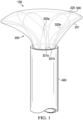
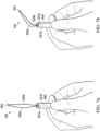
- embodiment 100 of the present invention comprises a deployment tube 400 with the self-expanding wire framework 200 having polymer film 221 and being partially deployed from the deployment tube 400.
- the DCCD device (not shown) can be attached to the self-expanding wire framework 100 before being drawn into the deployment tube 400.
- FIG. 1 shows the device 100 having a framework 200 with the polymer film 221 in contact six articulated wire loops 220 being deployed from tube 400.
- the leading edge or top segments 300 forms a framework 200 encloses the deployed device 100 around the heart (not shown).
- the self-expanding wire framework 200 comprises multiple articulated wire loops 220 adjacent each other but not intertwined and disposed in a polymer film 221.
- Each of the articulated wire loops 220 includes the midway bends 320a and 320b to create tension when the midway bends 320a and 320b rotate and straighten.
- the articulated wire loops 220 include strut 321a extending from midway bends 320a and strut 321b extending from midway bends 320b.
- FIG. 1 shows the device 100 having a framework 200 with the polymer film 221 in contact six articulated wire loops 220 being deployed from tube 400.
- the leading edge or top segments 300 forms a framework 200 encloses the deployed
- the top segment 300 is pointed outwards or flaring, by doing so, the left and right midway bends 320a and 320b.
- the left and right midway bends 320a and 320b must become straighter or unbend forming a configuration with higher elastic energy.
- left and right midway bends 320a and 320b of each further rotate and straighten out this will orient the top segment 300 to straighten out from the initial flaring motion when the framework is first deployed.
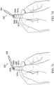
- FIGS. 2a and 2b depict a schematic diagram of the elements of self-expanding wire framework 200 with a polymer film 221 covering.
- the self-expanding wire framework 200 is comprised of multiple articulate wire loops 220a-e, each comprising of a left and a right midway bends 320a and 320b that extend as struts 321a and 321b to hub (not shown).
- the top segment 300 of each articulated loops 220 is bent and compressed together to fit inside the deployment tube (not shown).
- the midway bends 320a and 320b of each articulated loop are straightened and compressed closer together to one another.
- midway bends 320a and 320b The unbending or straightening of midway bends 320a and 320b is unstable causing it to twist or rotate rather than becoming a straight line (when struts 321a and 321b are not fixed relative to each other).
- the left and right midway bends 320a and 320b of each articulated loop 220 are compressed closer together, the left and right midway bends 320a and 320b rotate and orient the top segment 300 out-of-plane creating a flaring motion.
- the unstable tendency of unbending makes the top segment 300 of each articulate loop 220 protrudes radially outwards away from the hoop dimension as the top segment 300 is partially deployed.
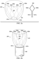
- FIG. 2a shows a schematic diagram and the overall shape of the self-expanding wire framework 200 having adjacent articulated wire loops 220a-e and polymer film 221 fully deployed from the deployment tube (not shown).
- the leading edge or top segment 300 forms a circular framework 200 that encloses the deployed device around the heart (not shown).
- the self-expanding wire frame 200 comprises multiple articulated wire loops 220a-e disposed in a polymer film 221.
- the articulated wire loops 220a-e are adjacent each other but not intertwined.
- the polymer film 221 may be on one side (inner surface or outer surface) of the multiple articulated wire loops 220.
- the polymer film 221 may be on both sides (inner surface and outer surface) of the multiple articulated wire loops 220a-e forming a sandwich configuration.
- the polymer film 221 may be a single film with the multiple articulated wire loops 220a-e disposed within the polymer film 221.
- Each of the articulated wire loops 220a-e includes the midway bends 320a and 320b as shown in the diagram to create tension when the midway bends 320a and 320b rotate and straighten.
- the articulated wire loops 220a-e include strut 321a extending from midway bends 320a and strut 321b extending from midway bends 320b.
- strut 321a and 321b are fixed relative each other so that the strut 321a and 321b themselves cannot rotate or turn thus forcing movement about the midway bends 320a and 320b.
- the left midway bend 320a and right midway bend 320b of each of the articulated wire loops 220a-e results in a tension that causes the self-expanding wire framework 200 to engage in a circumferential flaring motion and end out of plane when deployed from the deployment tube (not shown).
- FIG. 2b shows a schematic diagram and the overall shape of the self-expanding wire framework 200 having overlapping articulated wire loops 220 with the polymer film 221 covering that is fully deployed from the deployment tube (not shown).
- the leading edge or top segment 300 forms a circular framework 200 that encloses the deployed device around the heart (not shown).
- the self-expanding wire framework 200 comprises multiple articulated wire loops 220 disposed in a polymer film 221 in a partially overlapping pattern with the adjacent wire loops 220 partially overlapping (but not intertwined).
- the polymer film 221 may be on one side (inner surface or outer surface) of the multiple articulated wire loops 220.
- the polymer film 221 may be on both sides (inner surface and outer surface) of the multiple articulated wire loops 220 forming a sandwich configuration.
- the polymer film 221 may be a single film with the multiple articulated wire loops 220 disposed with in the polymer film 221.
- Each of the articulated wire loops 220 includes the midway bends 320a and 320b as shown in the diagram to create tension when the midway bends 320a and 320b rotate and straighten.
- the articulated wire loops include strut 321a extending from midway bends 320a and strut 321b extending from midway bends 320b.
- the position of strut 321a and 321b are fixed relative to each other so that the strut 321a and 321b cannot rotate or turn forcing movement about the midway bends 320a and 320b.
- the left midway bend 320a and right midway bend 320b of each of the articulated wire loops 220 results in a tension that causes the self-expanding wire framework 200 to engage in a circumferential flaring motion and end out of plane when deployed from the deployment tube. Further deployment of the framework 200 allows the left and right midway bends 320a and 320b of each of the articulated wire loops 220 making up the framework 200 to straighten out in a configuration with higher elastic energy which reorients the top segment 300 back towards the center.
- the self-expanding wire framework 200 has partially overlapping articulated wire loops 220 which are covered by polymer film 221.
- Each articulated wire loop has a left midway bend 320a and a right midway bend 320b.
- the adjacent wire loop at least partially overlaps a second wire loop by placing the left midway bend of a first wire loop behind the right midway bend of the second wire loop this pattern is repeated until the desired number of the articulated wire loops are achieved.
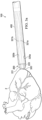
- FIGS. 3a - 3b depict an embodiment of the present invention at successive amounts of deployment about a plastic mock heart 2 (3D printed from a CT scan of a normal adult sheep).
- FIGS. 3a-3e illustrated the flaring and straightening of the framework 200 as it was deployed from the deployment tube 400. However, the flaring motion can also be observed with just a single articulated wire loop as seen in FIGS. 4-8 .
- FIG. 3a shows the self-expanding wire framework 200 compressed inside deployment tube 400 as it is deployed about a plastic mock heart 2.
- FIG. 3a shows a polymer film 221 with an articulated wire loop 220 with the top segment 300 flanked by the left and right midway bends 320a and 320b and include strut 321a extending from midway bends 320a and strut 321b extending from midway bends 320b as it is deployed from the deployment tube 400.
- the articulated wire loop 220 is deployed from the deployment tube 400 such that the left and right midway bends 320a and 320b are within the deployment tube 400.
- FIG. 3b shows the initial deployment of framework 200 wherein the top segments 300 of each of the articulated wire loop 220 are beginning to engage in a circumferential flaring motion and bend out of plane as it is deployed about a plastic mock heart 2.
- FIG. 3b shows a polymer film 221 with an articulated wire loop 220 with the top segment 300 flanked by the left and right midway bends 320a and 320b and include strut 321a extending from midway bends 320a and strut 321b extending from midway bends 320b as it is deployed from the deployment tube 400.
- the articulated wire loop 220 is deployed from the deployment tube 400 such that the left and right midway bends 320a and 320b are extending from the deployment tube 400.
- FIG. 3c illustrates the framework deployed to the midway bends 320 which are bent outwards flaring the top segment 300 out.
- FIG. 3c shows a polymer film 221 with an articulated wire loop 220 with the top segment 300 flanked by the left and right midway bends 320a and 320b and include strut 321a extending from midway bends 320a and strut 321b extending from midway bends 320b as it is deployed from the deployment tube 400.
- the articulated wire loop 220 is deployed from the deployment tube 400 such that the left and right midway bends 320a and 320b and the polymer film 221 are extending past the deployment tube 400.
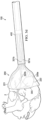
- FIG. 3d shows the struts 321a and 321b connected to midway bends 320a and 320b which straighten out to configure to a form of higher elastic energy.
- the framework 200 is deployed pass the midway bends 320, about a plastic mock heart 2.
- FIG. 3d shows a polymer film 221 with an articulated wire loop 220 with the top segment 300 flanked by the left and right midway bends 320a and 320b and include strut 321a extending from midway bends 320a and strut 321b extending from midway bends 320b as it is deployed from the deployment tube 400.
- the articulated wire loop 220 is deployed from the deployment tube 400 such that the left and right midway bends 320a and 320b are extending past the deployment tube 400. As the midway bends 320a and 320b are straightened out, the top segment 300 of each articulated wire loop 220 are reoriented inwards from the initial flared position. The reorientation of the articulated wire loops 220 allows the top segment 300 of each wire loop 220 and the polymer film 221 to make contact with the outer circumference of the heart 2.
- FIG. 3e illustrates the full deployment of the framework 200 as each articulated wire loop 220 is further expanded to encircle a larger portion of the heart 2.
- the framework 200 is deployed pass the midway bends 320, about a plastic mock heart 2.
- FIG. 3e shows a polymer film 221 with an articulated wire loop 220 with the top segment 300 flanked by the left and right midway bends 320a and 320b and include strut 321a extending from midway bends 320a and strut 321b extending from midway bends 320b as it is deployed from the deployment tube 400.
- the articulated wire loop 220 is deployed from the deployment tube 400 such that the left and right midway bends 320a and 320b and the polymer film 221 are extending past the deployment tube 400 to encircle a larger portion of the heart 2.
- the self-expanding wire framework device of the present invention includes multiple articulated wire loops with a polymer film connected thereto.
- the number of articulated wire loops used is at the discretion of the manufacturer and depends on the size of the deployable device. As little as 2 articulated wire loops can be used, but the number can increase to 3, 4, 5, 6, 7, 8, 9, 10, 11, 12, or more articulated wire loops linked.
- Each of the articulated wire loops include struts that connect the midway bends to the hub (not shown). The struts are fixed in position relative to the midway bends to induce flaring when extended from the deployment tube. The fixation location can vary with the deployment of the framework as tension between the articulate wire loops may move the linkage. However, the struts between the loops may also be fixated to limit the maximum expansion size of the wire framework.
- FIGS. 4a-4d depicts a side view of an embodiment of the present invention showing a single articulated wire loop 220 being drawn into the deployment tube 400.
- the articulated loop 220 is beginning to be drawn into the deployment tube 400 which compresses the left and right midway bends 320a and 320b together to allow top segments 300 to move inwardly.
- the articulated loop 220 is beginning to be drawn into the deployment tube 400 which compresses the left and right midway bends 320a and 320b together. At this point, flaring of the top segment 300 is evident between FIGS. 4a and 4b .
- FIG. 4c shows an oriented wire loop 220 with the left and right midway bends 320a and 320b bent and flaring the top segment 300 outwardly.
- FIG. 4d shows the articulated wire loop 220 drawn into the deployment tube 400 to the left and right midway bends 320a and 320b.
- Each of the articulated wire loops 220 will have a pair of struts extending into the deployment tube 400 that may or may not be compressed. The present invention would still function if the loop ends were crossed or parallel within the deployment tube 400.
- FIGS. 5a-5d depicts a frontal view of the single articulated wire loop 220 being drawn into the deployment tube 400 and correspond with FIGS. 4a-4d respectively.
- the bending and flaring of the midway bends 320a and 320b in the deployment tube 400 cannot be seen in the frontal view, but the compression of the midway bends 320a and 320b together is clear.
- FIGS. 5b and 5c show the reorientation of the wire loop 220 as the midway bends 320a and 320b are compressed into the deployment tube 400.
- FIG. 5d shows that after the midway bends 320a and 320b are reached, the rest of the wire loop up to the top segment 300 are compressed together to be drawn into the deployment tube 400.
- this compressed form is the configuration the loop 220 will be deployed at which leads to the initial flaring out position shown in FIG. 4d when the wire loop 220 is first deployed.
- the apparatus is adapted to permit deployment of a deployable device, such as a heart assist or cardiac compression device; the self-expanding wire framework equipped with the deployable device being collapsible to fit inside the deployment tube to be positioned near the heart, and then deployed to advance around a heart without the need of any guidewires; the apparatus comprising a minimal number of components-including a self-expanding wire framework adapted to engage a deployable device, expand the deployable device and guide the deployable device during deployment; and the self-expanding wire framework and deployment tube being separated or integrated into a single unit.
- a deployable device such as a heart assist or cardiac compression device
- the self-expanding wire framework equipped with the deployable device being collapsible to fit inside the deployment tube to be positioned near the heart, and then deployed to advance around a heart without the need of any guidewires
- the apparatus comprising a minimal number of components-including a self-expanding wire framework adapted to engage a deployable device, expand
- the wire used for constructing the self-expanding wire frame will need to be an appropriate wire stiffness to achieve desired expansion and flaring out but not cause inversion of the wireframe during deployment.
- the use of quadrilateral or non-round wires will allow orienting the wire cross section such that it naturally causes the flaring motion upon deployment from the deployment tube.
- An example would be a rectangular wire with the long length of the cross-section oriented along the periphery of the device, around the heart.
- the self-expanding wire fragment should be in a flaring position with the top segment 300 of each of the articulated wire loops out of plane.
- the midway bends of the articulated wire loop can be made more rounded to allow for gradual flaring as the framework is deployed.
- the midway bends can also comprise multiple bends (two bends instead of one midway bend).
- Other embodiments can include 3, 4, 5 or more bends depending on the preference of the manufacturer.
- the diamond shape of the articulated wire loop is not the only possible element design. Various other shapes and designs are possible as long as there is a bending top segment 300 and midway bends in a left segment and a right segment that bend outward when the wire loop is collapsed and packed into the deployment tube.
- FIG. 6a shows a schematic of an embodiment of articulated wire loop 240 with the top segment 300 flanked by the left and right midway bends 320a and 320b which are more rounded and include strut 321a extending from midway bends 320a and strut 321b extending from midway bends 320b into the deployment tube (not shown).
- Another embodiment includes articulated wire loop 260 with the top segment 300 flanked by the left and right midway bends 320a and 320b which are more flat and include strut 321a extending from midway bends 320a and strut 321b extending from midway bends 320b into the deployment tube (not shown).
- FIG. 6b shows an articulated wire loop 240 with the top segment 300 flanked by the left and right midway bends 320a and 320b which are more rounded and include strut 321a extending from midway bends 320a and strut 321b extending from midway bends 320b into the deployment tube 400.
- FIG. 6c shows an articulated wire loop 260 with the top segment 300 flanked by the left and right midway bends 320a and 320b which are more flat and include strut 321a extending from midway bends 320a and strut 321b extending from midway bends 320b into the deployment tube 400.
- FIGS. 7a-7d illustrate a side view of articulated wire loop 240 being drawn into deployment tube 400.
- FIG. 7a shows an articulated wire loop 240 with the top segment 300 flanked by the left and right midway bends 320a and 320b which are more rounded and include strut 321a extending from midway bends 320a and strut 321b extending from midway bends 320b drawn into the deployment tube 400.
- FIG. 7b shows an articulated wire loop 240 with the top segment 300 flanked by the left and right midway bends 320a and 320b which are more rounded and include strut 321a extending from midway bends 320a and strut 321b extending from midway bends 320b drawn into the deployment tube 400.
- FIG. 7c shows an articulated wire loop 240 with the top segment 300 flanked by the left and right midway bends 320a and 320b which are more rounded and include strut 321a extending from midway bends 320a and strut 321b extending from midway bends 320b drawn into the deployment tube 400.
- the articulated wire loop 240 is drawn into the deployment tube 400 to the left and right midway bends 320a and 320b.
- FIG. 7d shows an articulated wire loop 240 with the top segment 300 flanked by the left and right midway bends 320a and 320b which are more rounded and include strut 321a extending from midway bends 320a and strut 321b extending from midway bends 320b drawn into the deployment tube 400.
- the articulated wire loop 240 is drawn into the deployment tube 400 such that the left and right midway bends 320a and 320b are within the deployment tube 400.
- FIG. 8a shows an articulated wire loop 260 with the top segment 300 flanked by the left and right midway bends 320a and 320b which are more rounded and include strut 321a extending from midway bends 320a and strut 321b extending from midway bends 320b drawn into the deployment tube 400.
- FIG. 8b shows an articulated wire loop 260 with the top segment 300 flanked by the left and right midway bends 320a and 320b which are more rounded and include strut 321a extending from midway bends 320a and strut 321b extending from midway bends 320b drawn into the deployment tube 400.
- FIG. 8c shows an articulated wire loop 260 with the top segment 300 flanked by the left and right midway bends 320a and 320b which are more rounded and include strut 321a extending from midway bends 320a and strut 321b extending from midway bends 320b drawn into the deployment tube 400.
- the articulated wire loop 240 is drawn into the deployment tube 400 to the left and right midway bends 320a and 320b.
- FIG. 8d shows an articulated wire loop 260 with the top segment 300 flanked by the left and right midway bends 320a and 320b which are more rounded and include strut 321a extending from midway bends 320a and strut 321b extending from midway bends 320b drawn into the deployment tube 400.
- the articulated wire loop 240 is drawn into the deployment tube 400 such that the left and right midway bends 320a and 320b are within the deployment tube 400.
- FIGS. 3a-3e Various attachment means may also be utilized between a polymer film chamber and the wire frame so as not to impede on desired bending.
- One example as shown in FIGS. 3a-3e is to strap the wires between layers of plastic.
- Another embodiment would be to allow wire movement and rotation within the polymer film attachment points.
- the words “comprising” (and any form of comprising, such as “comprise” and “comprises”), “having” (and any form of having, such as “have” and “has”), "including” (and any form of including, such as “includes” and “include”) or “containing” (and any form of containing, such as “contains” and “contain”) are inclusive or open-ended and do not exclude additional, unrecited elements or method steps.
- compositions and/or methods disclosed and claimed herein can be made and executed without undue experimentation in light of the present disclosure. While the compositions and methods of this invention have been described in terms of preferred embodiments, it will be apparent to those of skill in the art that variations may be applied to the compositions without departing from the scope of the invention. All such similar substitutes and modifications apparent to those skilled in the art are deemed to be within the scope of the invention as defined by the appended claims.
Landscapes
- Health & Medical Sciences (AREA)
- Cardiology (AREA)
- Engineering & Computer Science (AREA)
- Heart & Thoracic Surgery (AREA)
- Veterinary Medicine (AREA)
- Biomedical Technology (AREA)
- Life Sciences & Earth Sciences (AREA)
- Animal Behavior & Ethology (AREA)
- General Health & Medical Sciences (AREA)
- Public Health (AREA)
- Anesthesiology (AREA)
- Hematology (AREA)
- Mechanical Engineering (AREA)
- Vascular Medicine (AREA)
- Oral & Maxillofacial Surgery (AREA)
- Transplantation (AREA)
- Prostheses (AREA)
Claims (11)
- Eine selbstexpandierende Drahtrahmenvorrichtung (100), aufweisend:ein Einsatzrohr (400) undeinen selbstexpandierenden Drahtrahmen (200), der innerhalb des Einsatzrohrs (400) positioniert ist und mit einer Polymerfolie (221) bedeckt ist, die so angepasst ist, dass sie sich nach außen ausdehnt, um einen Teil eines Herzes zu umschließen, wobei der selbstexpandierende Drahtrahmen (200) aufweist:
eine Reihe benachbarter gelenkiger Drahtschleifen, die sich von einer Vorderkante zu einer Nabe erstrecken, dadurch gekennzeichnet, dass jede der gelenkigen Drahtschleifen (200) der Reihe von gelenkigen Drahtschleifen aufweist:ein oberes Segment (300), das an der Vorderkante positioniert ist und sich zu einer linken Mittelbiegung (320a) und zu einer rechten Mittelbiegung (320b) erstreckt,eine linke Strebe (321a), die sich von der linken Mittelbiegung (320a) zur Nabe erstreckt,eine rechte Strebe (321b), die sich von der rechten Mittelbiegung (320b) zur Nabe erstreckt, undeinen festen Strebenbefestigungspunkt an der Nabe, um die Position der linken Strebe (321a) und der rechten Strebe (321b) zu fixieren,wobei jede der gelenkigen Drahtschleifen (220) der Reihe von gelenkigen Drahtschleifen so positioniert ist, dass sie zumindest teilweise eine benachbarte gelenkige Drahtschleife überlappt, undwobei die linke Mittelbiegung (320a) und die rechte Mittelbiegung (320b) zu einer Spannung führen, die bewirkt, dass die Reihe von gelenkigen Drahtschleifen eine umfangsmäßige Ausweitung ausführt und sich nach außen biegt, wenn der selbstexpandierende Rahmen (200) aus dem Einsatzrohr (400) eingesetzt wird, um den selbstexpandierenden Drahtrahmen (200) und die Polymerfolie (221) nach außen aufzufächern. - Die selbstexpandierende Rahmenvorrichtung (100) nach Anspruch 1, wobei die linken Mittelbiegungen (320a) und die rechten Mittelbiegungen (320b) abgerundet sind, um eine allmähliche Ausweitung zu ermöglichen, wenn der selbstexpandierende Drahtrahmen (200) eingesetzt wird, oder wobei die linken Mittelbiegungen (320a) und die rechten Mittelbiegungen (320a) abgeflacht sind, um eine Ausweitung zu ermöglichen, wenn der selbstexpandierende Drahtrahmen (200) eingesetzt wird.
- Die selbstexpandierende Rahmenvorrichtung (100) nach Anspruch 1 oder 2, wobei die linken Mittelbiegungen (320a) und die rechten Mittelbiegungen (320b) weitere Mehrfachbiegungen aufweisen, um sofortige Ausweitungspositionen zu ermöglichen, wenn der selbstexpandierende Drahtrahmen (200) eingesetzt wird.
- Die selbstexpandierende Rahmenvorrichtung (100) nach einem der Ansprüche 1 bis 3, wobei die gelenkigen Drahtschleifen (220) flache Drähte, ovale Drähte, runde Drähte, nicht-runde Drähte aufweisen.
- Die selbstexpandierende Rahmenvorrichtung (100) nach einem der Ansprüche 1 bis 4, wobei die Reihe von gelenkigen Drahtschleifen mindestens 2, 3, 4, 5, 6, 7, 8, 9, 10, 11, 12, 13, 14, 15, 16, 17, 18, 19, 20 oder mehr gelenkige Drahtschleifen (220) aufweist.
- Die selbstexpandierende Rahmenvorrichtung (100) nach einem der Ansprüche 1 bis 5, wobei die linke Strebe (321a) zwischen der Mittelbiegung und der Nabe mit der rechten Strebe (321b) verflochten ist.
- Die selbstexpandierende Rahmenvorrichtung (100) nach einem der Ansprüche 1 bis 6, wobei die linke Strebe (321a) und die rechte Strebe (321b) separat an der Nabe verbunden sind.
- Die selbstexpandierende Rahmenvorrichtung (100) nach einem der Ansprüche 1 bis 7, wobei jede der gelenkigen Drahtschleifen (220) der Reihe von gelenkigen Drahtschleifen neben einer benachbarten gelenkigen Drahtschleife (220) positioniert ist.
- Die selbstexpandierende Rahmenvorrichtung (100) nach einem der Ansprüche 1 bis 8, wobei die Polymerfolie (221) auf der Innenseite des selbstexpandierenden Drahtrahmens (200), auf der Außenseite des selbstexpandierenden Drahtrahmens (200) oder auf der Innen- und Außenseite angeordnet ist, um den selbstexpandierenden Drahtrahmen (200) einzuschließen.
- Die selbstexpandierende Rahmenvorrichtung (100) nach einem der Ansprüche 1 bis 9, wobei die linke Strebe (321a) und die rechte Strebe (321b) jeweils ein Biegeende aufweisen, das mit der Mittelbiegung verbunden ist, und ein Nabenende, wobei das Nabenende an der Nabe an einem festen Strebenbefestigungspunkt befestigt ist.
- Die selbstexpandierende Rahmenvorrichtung (100) nach einem der Ansprüche 1 bis 10, wobei das Einsatzrohr (400) eine äußere Oberfläche aufweist, die einen inneren Durchgang umgibt, und eine Einsatzöffnung an einem Ende des inneren Durchgangs aufweist, wobei der mit einer Polymerfolie (221) bedeckte selbstexpandierende Drahtrahmen (200) verschiebbar im inneren Durchgang positioniert ist, um verschiebbar aus der Einsatzöffnung herauszutreten und so angepasst ist, dass er sich nach außen ausweitet, um einen größeren Teil des Herzens zu umschließen.
Applications Claiming Priority (2)
| Application Number | Priority Date | Filing Date | Title |
|---|---|---|---|
| US201562192725P | 2015-07-15 | 2015-07-15 | |
| PCT/US2016/042578 WO2017011778A1 (en) | 2015-07-15 | 2016-07-15 | Self-expanding heart assist device |
Publications (3)
| Publication Number | Publication Date |
|---|---|
| EP3322380A1 EP3322380A1 (de) | 2018-05-23 |
| EP3322380A4 EP3322380A4 (de) | 2019-02-27 |
| EP3322380B1 true EP3322380B1 (de) | 2025-01-08 |
Family
ID=61951700
Family Applications (1)
| Application Number | Title | Priority Date | Filing Date |
|---|---|---|---|
| EP16825268.2A Active EP3322380B1 (de) | 2015-07-15 | 2016-07-15 | Selbstexpandierende herzunterstützungsvorrichtung |
Country Status (2)
| Country | Link |
|---|---|
| EP (1) | EP3322380B1 (de) |
| CN (1) | CN108289729B (de) |
Family Cites Families (5)
| Publication number | Priority date | Publication date | Assignee | Title |
|---|---|---|---|---|
| US9510746B2 (en) * | 2004-06-17 | 2016-12-06 | The Texas A&M University System | Deployment methods and mechanisms for minimally invasive implantation of heart contacting cardiac devices |
| US7524282B2 (en) * | 2005-08-29 | 2009-04-28 | Boston Scientific Scimed, Inc. | Cardiac sleeve apparatus, system and method of use |
| US8192351B2 (en) * | 2007-08-13 | 2012-06-05 | Paracor Medical, Inc. | Medical device delivery system having integrated introducer |
| AU2009302945C1 (en) * | 2008-10-10 | 2016-04-21 | Medicaltree Patent Ltd | Heart help device, system, and method |
| CA2740443C (en) * | 2008-10-20 | 2016-06-21 | Corassist Cardiovascular Ltd. | Ventricular function assisting device and a method and apparatus for implanting it |
-
2016
- 2016-07-15 CN CN201680047566.7A patent/CN108289729B/zh active Active
- 2016-07-15 EP EP16825268.2A patent/EP3322380B1/de active Active
Also Published As
| Publication number | Publication date |
|---|---|
| CN108289729B (zh) | 2021-01-12 |
| EP3322380A4 (de) | 2019-02-27 |
| CN108289729A (zh) | 2018-07-17 |
| EP3322380A1 (de) | 2018-05-23 |
Similar Documents
| Publication | Publication Date | Title |
|---|---|---|
| US10463496B2 (en) | Self-expanding heart assist device | |
| JP7528068B2 (ja) | 人工心弁デバイス、システム、および方法 | |
| US9833318B2 (en) | Self-expanding heart assist device | |
| CN111031967B (zh) | 具有系带连接特征的人造心脏瓣膜 | |
| US10631839B2 (en) | Implantable device | |
| US10799348B2 (en) | Reinforced inflatable medical devices | |
| CN105073068B (zh) | 可快速部署的外科心脏瓣膜 | |
| EP4344676A1 (de) | Prothetische klappe und einsetzsystem | |
| EP3691568B1 (de) | Perkutane shunt-vorrichtungen | |
| CN109640836A (zh) | 带有用于插入心包腔中的柔性尖端的组织锚 | |
| WO2015173609A1 (en) | Implant device and implantation kit | |
| CN102883684A (zh) | 人工心脏瓣膜 | |
| WO2008038276A2 (en) | Method and system for improving diastolic function of the heart | |
| CN103237524A (zh) | 人工心脏瓣膜 | |
| CN112773559A (zh) | 一种新型覆膜支架 | |
| JP2018520783A5 (de) | ||
| US20220296865A1 (en) | Percutaneous potts shunt devices and related methods | |
| US20220054259A1 (en) | Flexible Anchor For Prosthetic Heart Valve | |
| EP3322380B1 (de) | Selbstexpandierende herzunterstützungsvorrichtung | |
| CN216124619U (zh) | 一种新型覆膜支架 | |
| US20220387173A1 (en) | Expandable Anchor For Prosthetic Mitral Valve | |
| US20250325268A1 (en) | Percutaneous shunt devices and methods | |
| US20090281372A1 (en) | Cardiac harness assembly for treating congestive heart failure and for defibrillation and/or pacing/sensing | |
| JPWO2021026541A5 (de) |
Legal Events
| Date | Code | Title | Description |
|---|---|---|---|
| STAA | Information on the status of an ep patent application or granted ep patent |
Free format text: STATUS: THE INTERNATIONAL PUBLICATION HAS BEEN MADE |
|
| PUAI | Public reference made under article 153(3) epc to a published international application that has entered the european phase |
Free format text: ORIGINAL CODE: 0009012 |
|
| STAA | Information on the status of an ep patent application or granted ep patent |
Free format text: STATUS: REQUEST FOR EXAMINATION WAS MADE |
|
| 17P | Request for examination filed |
Effective date: 20180115 |
|
| AK | Designated contracting states |
Kind code of ref document: A1 Designated state(s): AL AT BE BG CH CY CZ DE DK EE ES FI FR GB GR HR HU IE IS IT LI LT LU LV MC MK MT NL NO PL PT RO RS SE SI SK SM TR |
|
| AX | Request for extension of the european patent |
Extension state: BA ME |
|
| DAV | Request for validation of the european patent (deleted) | ||
| DAX | Request for extension of the european patent (deleted) | ||
| A4 | Supplementary search report drawn up and despatched |
Effective date: 20190129 |
|
| RIC1 | Information provided on ipc code assigned before grant |
Ipc: A61F 2/24 20060101ALI20190123BHEP Ipc: A61F 2/00 20060101AFI20190123BHEP Ipc: A61M 1/10 20060101ALI20190123BHEP Ipc: A61M 1/12 20060101ALI20190123BHEP |
|
| STAA | Information on the status of an ep patent application or granted ep patent |
Free format text: STATUS: EXAMINATION IS IN PROGRESS |
|
| 17Q | First examination report despatched |
Effective date: 20230404 |
|
| GRAP | Despatch of communication of intention to grant a patent |
Free format text: ORIGINAL CODE: EPIDOSNIGR1 |
|
| STAA | Information on the status of an ep patent application or granted ep patent |
Free format text: STATUS: GRANT OF PATENT IS INTENDED |
|
| RIC1 | Information provided on ipc code assigned before grant |
Ipc: A61F 2/24 20060101ALI20240709BHEP Ipc: A61M 60/865 20210101ALI20240709BHEP Ipc: A61M 60/839 20210101ALI20240709BHEP Ipc: A61M 60/468 20210101ALI20240709BHEP Ipc: A61M 60/289 20210101ALI20240709BHEP Ipc: A61M 60/191 20210101ALI20240709BHEP Ipc: A61F 2/00 20060101AFI20240709BHEP |
|
| INTG | Intention to grant announced |
Effective date: 20240801 |
|
| GRAS | Grant fee paid |
Free format text: ORIGINAL CODE: EPIDOSNIGR3 |
|
| GRAA | (expected) grant |
Free format text: ORIGINAL CODE: 0009210 |
|
| STAA | Information on the status of an ep patent application or granted ep patent |
Free format text: STATUS: THE PATENT HAS BEEN GRANTED |
|
| AK | Designated contracting states |
Kind code of ref document: B1 Designated state(s): AL AT BE BG CH CY CZ DE DK EE ES FI FR GB GR HR HU IE IS IT LI LT LU LV MC MK MT NL NO PL PT RO RS SE SI SK SM TR |
|
| REG | Reference to a national code |
Ref country code: GB Ref legal event code: FG4D |
|
| REG | Reference to a national code |
Ref country code: CH Ref legal event code: EP |
|
| REG | Reference to a national code |
Ref country code: DE Ref legal event code: R096 Ref document number: 602016090908 Country of ref document: DE |
|
| REG | Reference to a national code |
Ref country code: IE Ref legal event code: FG4D |
|
| P01 | Opt-out of the competence of the unified patent court (upc) registered |
Free format text: CASE NUMBER: APP_2853/2025 Effective date: 20250117 |
|
| REG | Reference to a national code |
Ref country code: LT Ref legal event code: MG9D |
|
| REG | Reference to a national code |
Ref country code: NL Ref legal event code: MP Effective date: 20250108 |
|
| REG | Reference to a national code |
Ref country code: AT Ref legal event code: MK05 Ref document number: 1757847 Country of ref document: AT Kind code of ref document: T Effective date: 20250108 |
|
| PG25 | Lapsed in a contracting state [announced via postgrant information from national office to epo] |
Ref country code: NL Free format text: LAPSE BECAUSE OF FAILURE TO SUBMIT A TRANSLATION OF THE DESCRIPTION OR TO PAY THE FEE WITHIN THE PRESCRIBED TIME-LIMIT Effective date: 20250108 |
|
| PG25 | Lapsed in a contracting state [announced via postgrant information from national office to epo] |
Ref country code: RS Free format text: LAPSE BECAUSE OF FAILURE TO SUBMIT A TRANSLATION OF THE DESCRIPTION OR TO PAY THE FEE WITHIN THE PRESCRIBED TIME-LIMIT Effective date: 20250408 |
|
| PG25 | Lapsed in a contracting state [announced via postgrant information from national office to epo] |
Ref country code: FI Free format text: LAPSE BECAUSE OF FAILURE TO SUBMIT A TRANSLATION OF THE DESCRIPTION OR TO PAY THE FEE WITHIN THE PRESCRIBED TIME-LIMIT Effective date: 20250108 |
|
| PG25 | Lapsed in a contracting state [announced via postgrant information from national office to epo] |
Ref country code: PL Free format text: LAPSE BECAUSE OF FAILURE TO SUBMIT A TRANSLATION OF THE DESCRIPTION OR TO PAY THE FEE WITHIN THE PRESCRIBED TIME-LIMIT Effective date: 20250108 |
|
| PG25 | Lapsed in a contracting state [announced via postgrant information from national office to epo] |
Ref country code: ES Free format text: LAPSE BECAUSE OF FAILURE TO SUBMIT A TRANSLATION OF THE DESCRIPTION OR TO PAY THE FEE WITHIN THE PRESCRIBED TIME-LIMIT Effective date: 20250108 |
|
| PG25 | Lapsed in a contracting state [announced via postgrant information from national office to epo] |
Ref country code: NO Free format text: LAPSE BECAUSE OF FAILURE TO SUBMIT A TRANSLATION OF THE DESCRIPTION OR TO PAY THE FEE WITHIN THE PRESCRIBED TIME-LIMIT Effective date: 20250408 Ref country code: IS Free format text: LAPSE BECAUSE OF FAILURE TO SUBMIT A TRANSLATION OF THE DESCRIPTION OR TO PAY THE FEE WITHIN THE PRESCRIBED TIME-LIMIT Effective date: 20250508 |
|
| PG25 | Lapsed in a contracting state [announced via postgrant information from national office to epo] |
Ref country code: HR Free format text: LAPSE BECAUSE OF FAILURE TO SUBMIT A TRANSLATION OF THE DESCRIPTION OR TO PAY THE FEE WITHIN THE PRESCRIBED TIME-LIMIT Effective date: 20250108 |
|
| PG25 | Lapsed in a contracting state [announced via postgrant information from national office to epo] |
Ref country code: PT Free format text: LAPSE BECAUSE OF FAILURE TO SUBMIT A TRANSLATION OF THE DESCRIPTION OR TO PAY THE FEE WITHIN THE PRESCRIBED TIME-LIMIT Effective date: 20250508 Ref country code: LV Free format text: LAPSE BECAUSE OF FAILURE TO SUBMIT A TRANSLATION OF THE DESCRIPTION OR TO PAY THE FEE WITHIN THE PRESCRIBED TIME-LIMIT Effective date: 20250108 |
|
| PG25 | Lapsed in a contracting state [announced via postgrant information from national office to epo] |
Ref country code: BG Free format text: LAPSE BECAUSE OF FAILURE TO SUBMIT A TRANSLATION OF THE DESCRIPTION OR TO PAY THE FEE WITHIN THE PRESCRIBED TIME-LIMIT Effective date: 20250108 Ref country code: GR Free format text: LAPSE BECAUSE OF FAILURE TO SUBMIT A TRANSLATION OF THE DESCRIPTION OR TO PAY THE FEE WITHIN THE PRESCRIBED TIME-LIMIT Effective date: 20250409 |
|
| PG25 | Lapsed in a contracting state [announced via postgrant information from national office to epo] |
Ref country code: AT Free format text: LAPSE BECAUSE OF FAILURE TO SUBMIT A TRANSLATION OF THE DESCRIPTION OR TO PAY THE FEE WITHIN THE PRESCRIBED TIME-LIMIT Effective date: 20250108 |
|
| PGFP | Annual fee paid to national office [announced via postgrant information from national office to epo] |
Ref country code: LU Payment date: 20250722 Year of fee payment: 10 |
|
| PG25 | Lapsed in a contracting state [announced via postgrant information from national office to epo] |
Ref country code: SE Free format text: LAPSE BECAUSE OF FAILURE TO SUBMIT A TRANSLATION OF THE DESCRIPTION OR TO PAY THE FEE WITHIN THE PRESCRIBED TIME-LIMIT Effective date: 20250108 |
|
| PG25 | Lapsed in a contracting state [announced via postgrant information from national office to epo] |
Ref country code: SM Free format text: LAPSE BECAUSE OF FAILURE TO SUBMIT A TRANSLATION OF THE DESCRIPTION OR TO PAY THE FEE WITHIN THE PRESCRIBED TIME-LIMIT Effective date: 20250108 |
|
| REG | Reference to a national code |
Ref country code: DE Ref legal event code: R097 Ref document number: 602016090908 Country of ref document: DE |
|
| PG25 | Lapsed in a contracting state [announced via postgrant information from national office to epo] |
Ref country code: DK Free format text: LAPSE BECAUSE OF FAILURE TO SUBMIT A TRANSLATION OF THE DESCRIPTION OR TO PAY THE FEE WITHIN THE PRESCRIBED TIME-LIMIT Effective date: 20250108 |
|
| PGFP | Annual fee paid to national office [announced via postgrant information from national office to epo] |
Ref country code: DE Payment date: 20250722 Year of fee payment: 10 |
|
| PGFP | Annual fee paid to national office [announced via postgrant information from national office to epo] |
Ref country code: BE Payment date: 20250722 Year of fee payment: 10 Ref country code: GB Payment date: 20250714 Year of fee payment: 10 |
|
| PGFP | Annual fee paid to national office [announced via postgrant information from national office to epo] |
Ref country code: FR Payment date: 20250723 Year of fee payment: 10 |
|
| PGFP | Annual fee paid to national office [announced via postgrant information from national office to epo] |
Ref country code: CH Payment date: 20250801 Year of fee payment: 10 |
|
| PG25 | Lapsed in a contracting state [announced via postgrant information from national office to epo] |
Ref country code: EE Free format text: LAPSE BECAUSE OF FAILURE TO SUBMIT A TRANSLATION OF THE DESCRIPTION OR TO PAY THE FEE WITHIN THE PRESCRIBED TIME-LIMIT Effective date: 20250108 Ref country code: CZ Free format text: LAPSE BECAUSE OF FAILURE TO SUBMIT A TRANSLATION OF THE DESCRIPTION OR TO PAY THE FEE WITHIN THE PRESCRIBED TIME-LIMIT Effective date: 20250108 |
|
| PGFP | Annual fee paid to national office [announced via postgrant information from national office to epo] |
Ref country code: IE Payment date: 20250724 Year of fee payment: 10 |
|
| PG25 | Lapsed in a contracting state [announced via postgrant information from national office to epo] |
Ref country code: RO Free format text: LAPSE BECAUSE OF FAILURE TO SUBMIT A TRANSLATION OF THE DESCRIPTION OR TO PAY THE FEE WITHIN THE PRESCRIBED TIME-LIMIT Effective date: 20250108 |
|
| PG25 | Lapsed in a contracting state [announced via postgrant information from national office to epo] |
Ref country code: SK Free format text: LAPSE BECAUSE OF FAILURE TO SUBMIT A TRANSLATION OF THE DESCRIPTION OR TO PAY THE FEE WITHIN THE PRESCRIBED TIME-LIMIT Effective date: 20250108 |
|
| PLBE | No opposition filed within time limit |
Free format text: ORIGINAL CODE: 0009261 |
|
| STAA | Information on the status of an ep patent application or granted ep patent |
Free format text: STATUS: NO OPPOSITION FILED WITHIN TIME LIMIT |
|
| 26N | No opposition filed |
Effective date: 20251009 |
|
| PG25 | Lapsed in a contracting state [announced via postgrant information from national office to epo] |
Ref country code: IT Free format text: LAPSE BECAUSE OF FAILURE TO SUBMIT A TRANSLATION OF THE DESCRIPTION OR TO PAY THE FEE WITHIN THE PRESCRIBED TIME-LIMIT Effective date: 20250108 |